Embed Size (px)
Citation preview
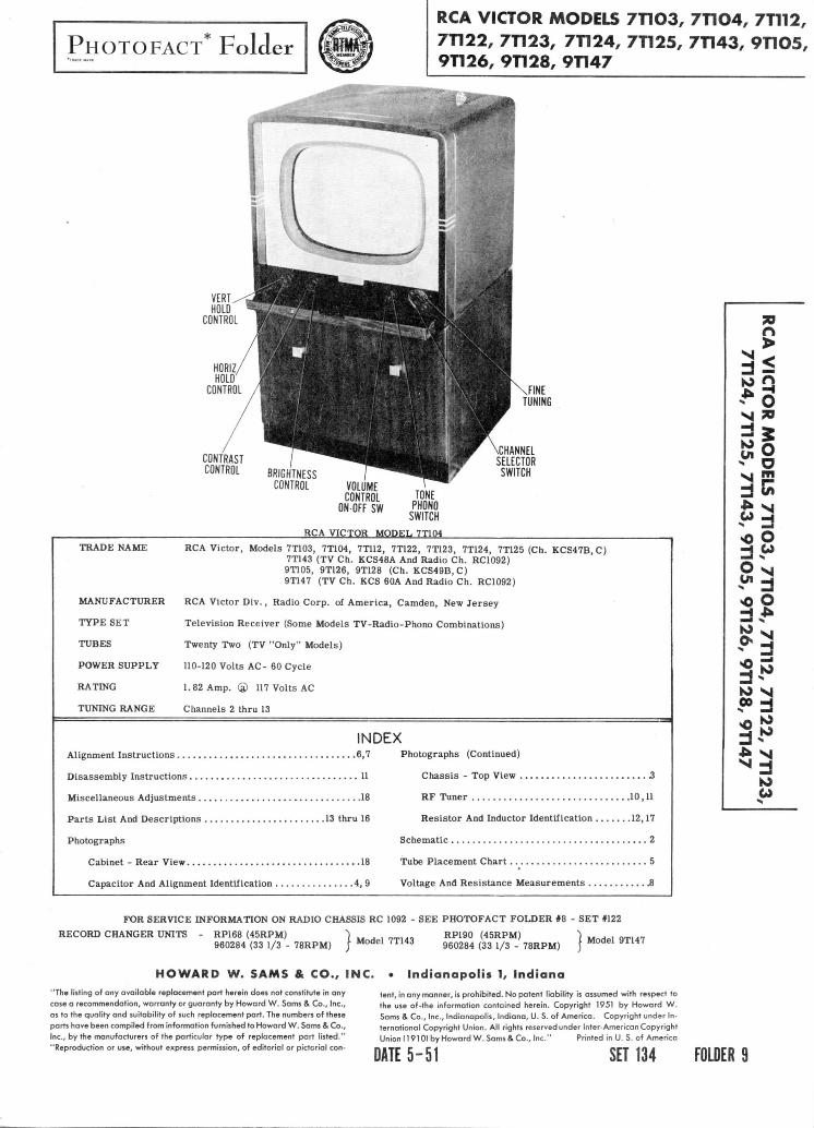
PHOTOFACT* Folder
RCA VICTOR MODELS 7T1O3, 7T1O4, 7T112,7T122, 7T123, 7T124, 7T125, 7T143, 9T1O5,9T126, 9T128, 9T147
VERTHOLD
CONTROL
HORIZHOLD
CONTROL
CONTRASTCONTROL BRIGHTNESS
CONTROL
FINETUNING
CHANNELSELECTOR
SWITCHVOLUME
CONTROLON-OFF M
TONEmm
RCA VICTOR MODEL 7T104
TRADE NAME RCA Victor, Models 7T103, 7T104, 7T112, 7T122, 7T123, 7T124, 7T125 (Ch. KCS47B.C)7T143 (TV Ch. KCS48A And Radio Ch. RC1092)9T105, 9T126, 9T128 (Ch. KCS49B.C)9T147 (TV Ch. KCS 60A And Radio Ch. RC1092)
MANUFACTURER RCA Victor Div., Radio Corp. of America, Camden, New Jersey
TYPE SET Television Receiver (Some Models TV-Radio-Phono Combinations)
TUBES Twenty Two (TV "Only" Models)
POWER SUPPLY 110-120 Volts AC- 60 Cycle
RATING 1.82 Amp. ® 117 Volts AC
TUNING RANGE Channels 2 thru 13
INDEXAlignment Instructions 6,7
Disassembly Instructions 11
Miscellaneous Adjustments 18
Parts List And Descriptions 13 thru 16
Photographs
Cabinet - Rear View 18
Capacitor And Alignment Identification 4, 9
Photographs (Continued)
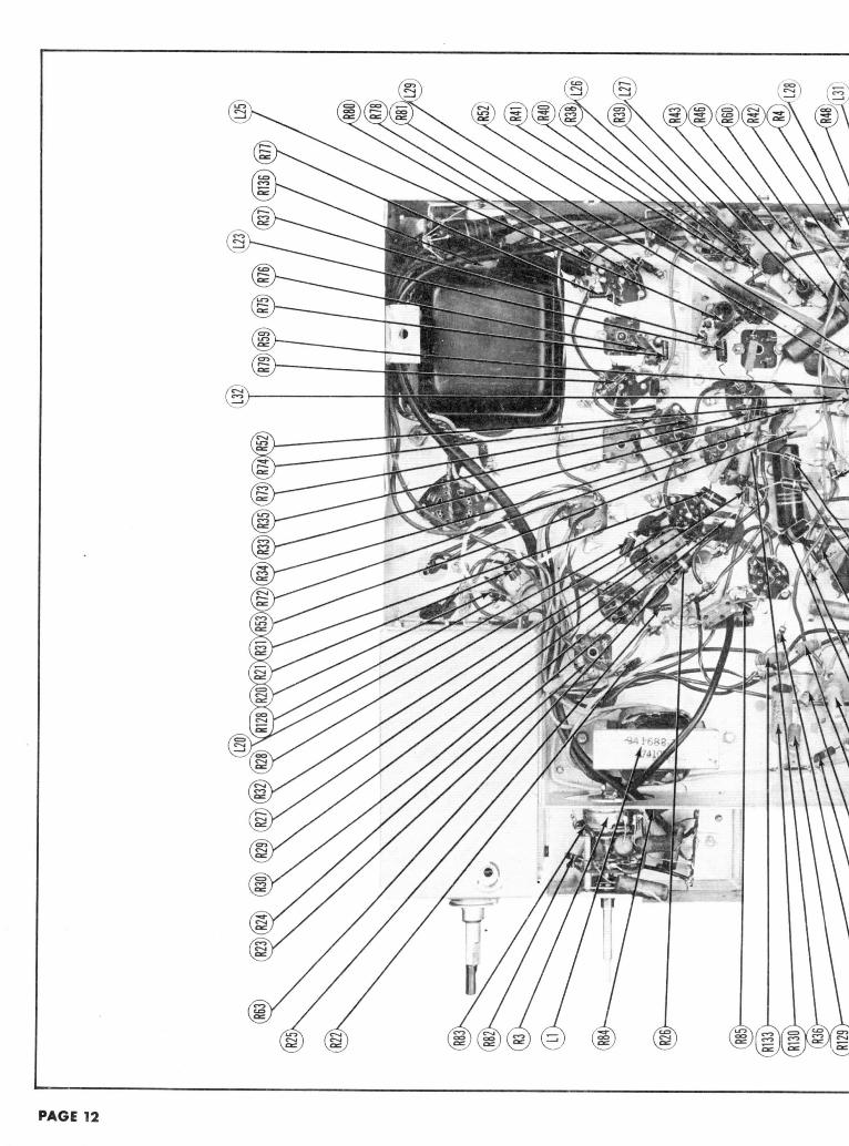
Chassis - Top View 2
RF Tuner 10,11
Resistor And Inductor Identification 12,17
Schematic .2
Tube Placement Chart 5
Voltage And Resistance Measurements JS
70
$
M »
wj m
2 K£3O O•̂1 CJ_d -i
O sisWU«O O
3?JJ3
FOR SERVICE INFORMATION ON RADIO CHASSIS RC 1092 - SEE PHOTOFACT FOLDER #8 - SET *122
RP190 (45RPM) ) Mode, 9TH7RECORD CHANGER UNITS - RP168 (45RPM)960284 (33 1/3 - 78RPM) Model 7T143 960284 (33 1/3 - 78RPM)
HOWARD W. SAMS & CO., INC. • Indianapolis 1, Indiana
"The listing of any available replacement part herein does not constitute in anycase a recommendation, warranty or guaranty by Howard W. Sams & Co., Inc.,as to the quality and suitability of such replacement part. The numbers of theseparts have been compiled from information furnished to Howard W. Sams & Co.,Inc., by the manufacturers of the particular type of replacement part listed.""Reproduction or use, without express permission, of editorial or pictorial con-
tent, in any manner, is prohibited. No patent liability is assumed with respect tothe use of-the information contained herein. Copyright 1951 by Howard W.Sams & Co., Inc., Indianapolis, Indiana, U. S. of America. Copyright under In-ternational Copyright Union. All rights reserved under Inter-American CopyrightUnion (1910) by Howard W. Sams & Co., Inc." Printed in U. S. of America
DATE 5-51 SET 134 FOLDER 9
THE COOPERATION OF THE MANUFACTURER OF THIS
RECEIVER MAKES IT POSSIBLE TO BRING YOU THIS SERVICE
A PHOTOFACT STANDARD NOTATION SCHEMATIC©Howard W. Sams & Co., Inc. 1951
PAGE 2
OUNO IF AMP
®6»U6• AMP- AGO CLA**> AUDIO OUT
(§>6AV6 ®6K1

RC
A V
ICT
OR
MO
DE
LS
7T
1O
3,
7T
1O
4,
7T
1 1
2,
7T
12
2,
7T
12
3,
7T
12
4,
7T
12
5,
7T
14
3,
9T
1O
5, 9
T1
26
, 9
T1
28
, 9
T1
47
E8

CH
AS
SIS
T
OP
VIE
W
'ecu
/ ''9
ZU
6 'S
OL
16 'E
fr L
IZ '
'zi u
z 'fr
oiiz
'co
u/
siaa
ow H
OIDI
A
* 3OVd

o m •OC
HA
SS
IS
BO
TT
OM
VIE
W-C
AP
AC
ITO
R
AN
D A
LIG
NM
EN
T
IDE
NT
IFIC
AT
ION
Zfr
U6
'8
Z.L
16
'91116
'S
OL
16 '
Cfr
liZ
'S
CL
J.Z
''C
ZL
1Z '
Cl
LIZ
'fr
OL
IZ '
CO
LIZ
S13
QO
W U
O13IA

L27e
VID
EO
DE
T.
AO
C R
EC
T'
^ ---- /
AU
DIO
OU
TP
UT
BO
TTO
M V
IEW
2ND
VID
EO
A
F A
MP
/V
4-
A
GC
CL
AM
P
©fL
63]
/viT
\5I
6J
(6
AU
6)
I 9
DIS
C.
LIM
ITE
R
IT
UB
E
PLA
CE
ME
NT
C
HA
RT
'8C
116 '9C
116
'SO
116 '
'CL
S13
QO
W «
O1D
IA

ALIGNMENT INSTRUCTIONSALIGNMENT INSTRUCTIONS— READ CAREFULLY BEFORE ATTEMPTING ALIGNMENT
The high voltage shock hazard may be eliminated by removing the horizontal oscillator tube, (V17), from its socket. •
VIDEO IF ALIGNMENT
Remove the converter tube, (V2), from its socket and replace it with a 6J6 which has Pin 1 removed. This will disable the local oscillator andprevent the possibility of erroneous indications.
Connect the negative lead of a 3 volt battery to the junction of R45 and C5. Connect the positive lead to chassis.
DUMMYANTENNA
Direct
"
"
"
"
DUMMYANTENNA
. 01MFD
"
SWEEPGENERATORCOUPLING
High side to an ungrounded tube shield floatingover dummy convertertube (V2). Low side tochassis.
"
"
"
"
"
SIGNALGENERATORCOUPLING
High side to Pin 1 (grid)of 6CB6, (V4). Low sideto chassis.
SWEEPGENERATORFREQUENCY
Not used
"
"
"
24MC(10MC SWP)
"
MARKERGENERATORFREQUENCY
21MC(Unmod. )
27MC
19. SMC
24. 35MC
22. SMC
21.75MC
25. SMC
21. 95MC24. SMC
21.85MC24. 75MC25. SMC26. 25MC
SOUND IF ALIGNMENSIGNAL
GENERATORFREQUENCY21MC(Unmod. )
"
CHANNEL
Any It
CHANNEL
Any
"
"
"
"
"
CONNECTSCOPE
USE VTVM -DC probe to Poin^^.Common to chassis.
"
"
"
"
Vert. amp. to Point<A>. Low side tochassis.
"
USING AM SIGNAL GENERATOR A
CONNECT ADJUSTVTVM ADJUST
)C probe^thru 1 meg A12, A13o Point <^>. Commono chassis.
C probe to Point <$>. A14ommon to chassis.
ADJUST
Al, A2
A3, A4,
A5
A6
A7
A8
A9
AID, All
REMARKS
Adjust for MINIMUM deflection.
"
Adjust for maximum deflection.
"
"
Shunt primarys of L21, L22, L24 and L27, (A6thru A9), with 300S2 carbon resistors. AdjustA10 and A 11 for response curve similar tofigure 1.
Remove the shunting resistors. Check forresponse curve similar to figure 2. If neces-
sary retouch A6 thru A 11 for proper response,.
ND VTVM
REMARKS
Adjust for maximum deflection.
Adjust for zero reading. A positive and negative readingwill be obtained on either side of the correct setting.
SOUND IF ALIGNMENT USING FM SIGNAL GENERATOR AND OSCILLOSCOPE
Use frequency modulated signal with 60 1* modulation and 450KC sweep. Use 1201 sawtooth voltage in scope for horizontal deflection.
DUMMYANTENNA
.01MFD
SWEEPGENERATORCOUPLING
High side to Pin 1 (Grid)of 6CB6, (V4). Lowside to chassis.
SWEEPGENERATORFREQUENCY
21MC(450KC SWP)
MARKERGENERATORFREQUENCY
21MC
CHANNEL
Any
CONNECTSCOPE
f" -t. amp. to Point. Low side tossis.
ADJUST
A12, A13M4
REMARKS
Adjust A14 so 21MC occurs at center of cross-over lines as per figure 3. Adjust A12 and A13for maximum amplitude and straightness ofcrossover lines.Continue with step 12.
RF TUNER ALIGNMENT
Remove the dummy converter tube and replace the original 6J6 in its socket.Connect the negative lead of a 3. 5 volt supply from a battery to terminal 3 of the HF unit terminal board, connect the positive lead to chassis.Disconnect the link between L18 and L19. Connect a 39S2 carbon resistor across terminal 1 and 2 on the terminal board, and loosely couple the link wire
to terminal 2.Detune A10 fully clockwise, (all the way out).Detune A27 fully counter clockwise, ( in later production L16 is fixed and cannot be tuned).Set the fine tuning control to the mid-position of its range.
DUMMYANTENNA
Two 120S!carbonresistors
SWEEPGENERATORCOUPLING
Across antenna terminalswith 12012 in each lead.
"
SWEEPGENERATORFREQUENCY
Not used
183MC(10MC SWP)
Not used
85 MC(10MC SWP)
MARKERGENERATORFREQUENCY
215.75MC
181.2SMC185. 75MC
87. 75MC
83.25MC87.75MC
CHANNEL
13
8
6
6
CONNECTSCOPE
VTVMDC probe to Point <£>Common to chassis.
SCOPEf-t. amp. to Point
. Low side tossis.
VTVMDC probe to Point <^>Common to chassis.
SCOPEVert. amp. to Point<g>. Low side tochassis.
ADJUST
A15
A16.A17,A18, A19
A20
A21, A22A23
REMARKS
Adjust for zero reading. A positive and neg-ative reading will be obtained on either side ofthe correct setting.
Adjust for response curve with bandwidthshown in figure 4.
Adjust for zero as in step 12.
Adjust for response curve similar to figure 4.
3.
4.
5.
F IG.I F IG.2 FIG. 3 F IG.4
PAGE 6

ALIGNMENT INSTRUCTIONS CCONTJ16.
17.
22.
23.
24.
25.
26.
Connect VTVM to Point D and adjust A24 for -3 volt reading. Recheck channel 6 response and if necessary retouch A21, A22 and A23 (or proper response.Repeat the retouching adjustments until proper channel 6 response is obtained with - 3 volts at Point D .
Two 12012carbonresistors
Across antenna terminalswith 120ft in each lead.
Not used
183MC(10MC SWP)
213MC(10MC SWP)
Not used
213MC(10MC SWP)207MC(10MC SWP)201MC(10MC SWP)195MC(10MC SWP)189MC(10MC SWP)183MC(10MC SWP)177MC(10MC SWP)
185.75MC
181. 25MC185.75MC
211.25MC215. 75MC
215.75MC
211.25MC215.75MC205.25MC209. 75MC199.25MC203. 75MC193.25MC197. 75MC187.25MC191.75MC181. 25MC185.75MC175.25MC179.75MC
8
8
13
13
13
12
11
10
9
8
7
VTVM -DC probe to Point <§>.Common to chassis.
SCOPEVflrt. amp. to Point<^>. Low side tochassis.
VTVM -DC probe to Point ̂Common to chassis.
SCOPEVert. amp. to Point<Q>. Low side tochassis.
A15
A25
A26
Adjust for zero reading. A positive and neg-ative reading will be obtained on either side ofthe correct setting.
Readjust A16, A17 and A19 for response curveand bandwidth shown in figure 4.
Ad' t -dthe markers. Then over shoot the adjustment3y tuning the slug in the same direction slightlymore than required for maximum amplitude.XeadjustA19 for maximum amplitude.
Adjust for zero reading as in step 17. Thenover shoot the adjustment as in step 19. Ad-just A15 to reset the oscillator to properfrequency.
Check all high band channels for proper re-sponse with markers above 80%. If markersdo not appear within 80% repeat step 13. IfA19 is adjusted the adjustment should be over-shot a small amount and compensated for byadjusting A25 for maximum amplitude betweenthe markers. If the valley in the top of thecurves on the high channels seems excessive,adjust A27 to flatten the curve. In later pro-ductions A27 may be fixed and not required ad-justment.
Check the oscillator frequency for the high band channels. If the oscillator is off frequency, over shoot the adjustment of A15 and compensate for itby adjusting A26 for zero voltage at Point C .
Repeat step 14.Two 120SJcarbonresistors
Across antenna terminal,with 120n in each lead.
85MC(10MC SWP)
83.25MC87.75MC
6 SCOPEVert. amp. to Point<§>. Low side tochassis.
Check for response curve similar to figure 4.If necessary retouch A21, A22 and A23 forproper response.
Check the voltage at Point D . If necessary adjust A24 for -3 volt reading. B A24 is adjusted turn channel selector to channel 8 and readjust A16 forproper response.
Two 12 0!Jcarbonresistors
Two 120Ocarbonresistors
Across antenna terminalswith 120n in each lead.
Across antenna terminalswith 120Siin each lead.
85MC(10MC SWP)
Not used
83.25MC87. 75MC
215.75MC
209. 75MC203.75MC197. 75MC191. 75MC185.75MC179. 75MC87.75MC
81.75MC71. 75MC65. 75MC59. 75MC
6
13
12111098765432
SCOPEVert. amp. to Point^^. Low side tochassis.
VTVM ,DC probe to Point <Q>Common to chassis.
A28A29A30A31A32A33A20A34A3 5A36A37
Check all low band channels for responsesimilar to figure 4 and the injection voltage atPoint D which should be - 3 volts. Also checkchannels 7 thru 13.
If necessary adjust A15 for zero voltage as instep 17.
Adjust for zero reading. A positive and neg-ative reading will be obtained on either side ofthe correct setting.
Turn channel switch to channel 8 and adjust A24 for proper response . When A24 is properly adjusted the response curve will be slightly wider with aslightly deeper valley in the center. Check all channels for: (1) proper response, (2) oscillator injection voltage at point D , and (3) oscillator frequency.Make slight touch up adjustments, if necessary. If A16 and A24 are changed considerably repeat step 28.
Disconnect the 39S2 resistor from terminals 1&2 on terminal strip and reconnect the link. Repeat steps 8 and 9 of VIDEO IF ALIGNMENT.
70O
N »
3§^S
-H2 NK> N»d
IOu
OSCILLATOR ALIGNMENT POINTS
PAGE 7

o mV
OLT
AG
E A
ND
RE
SIS
TAN
CE
M
EA
SU
RE
ME
NT
SVO
LTAG
E RE
ADIN
GS
RESI
STAN
CE R
EADI
NGS
Item
V 1
V 2
V 3
V 4
V 5
V6
V7
V 8
V9
V
10
V 1
1
V1
2
V1
3
V
14
V
15
V
16
V
17
V
18
V 1
9
V2
0
V
21
V2
2
Tube
6CB
6
6J6 6A
U6
6CB
6
6AU
6
6CB
6
6AL
5
12A
U7
12A
U7
6AU
6
6AU
6
6AL
5
6AV
6
6K6G
T
6SN
7GT
6K6G
T
6SN
7GT
6BG
6G
6W4G
T
1B3G
T
5U4G
17C
P4
Pin
1
-.2
VD
C
65V
DC
- . 3
VD
C
-.3
VD
C
-.3
VD
C
0V 0V 100V
DC
2.6
VD
C
-.1V
DC
-.8
VD
C
0V -1.4
VD
C
U2V
DC
-15V
DC
-60V
DC
ov -2.6
VD
C
365V
DC
OV
Pin
2
.3V
DC
130V
DC
OV .6V
DC
OV 1.6V
DC
-.2
VD
C
-.4
VD
C
-.2
VD
C
OV OV -.5
VD
C
OV 6.3
VA
C38
0VD
C12
0VD
C
OV 120V
DC
6.3
VA
C
OV
Pin
3
OV
OV OV 6.3
VA
C
OV 6.3
VA
C
OV 6VD
C
1.4V
DC
OV OV 6. 3
VA
C
6. 3
VA
C
» 21
5 V
DC
OV 355V
DC
330V
DC
-25V
DC
11V
DC
8VD
C
600V
DC
Pin
4
6.3
VA
C
6.3
VA
C
6.3
VA
C
OV 6.3
VA
C
OV 6. 3
VA
C
6.3
VA
C
6 . 3
VA
C
6.3
VA
C
6 . 3
VA
C
1.2V
AC
OV „ 22
5VD
C
2.5
VD
C35
5VD
C33
0VD
C
-70V
DC
OV
OV
Pin
5
160
VD
C
-1.7
VD
C
105V
DC
100V
DC
90V
DC
140V
DC
6VD
C
6.3
VA
C
6. 3
VA
C
110V
DC
110V
DC
OV - . 3
VD
C
»O
V
55V
DC
OV
205V
DC
-15V
DC
-20V
DC
360V
DC
Pin
6
90V
DC
S-2
.8V
DC
115V
DC
95V
DC
115V
DC
120V
DC
OV
.155
VD
C
2. 5
VD
C
UO
VD
C
75V
DC
OV -.3
VD
C
OV
4.6
VD
C40
VD
COV OV OV O
V
Pin
7
OV OV .6V
DC
OV .6V
DC
OV -.4
VD
C
»OV
OV .6V
DC
OV - . 5
VD
C
70V
DC
OV 6.3
VA
C
6.3
VA
C
OV OV
600V
DC
Pin
8
i3V
DC
1.7
VD
C
»15V
DC
OV 50V
DC
30V
DC
6. 3
VA
C32
0VD
C31
0VD
C
600V
DC
Pin
9
OV OV Top
Cap
» D
O N
OT
M
EA
SU
RE
OV
OV
370V
DC
.5V
DC
OV PIN
10
365V
DC
360V
AC
PIN
11
115V
DC
OVPI
N 1
26
.3V
AC
360V
AC
OV
370V
DC
Item
V 1
V 2
V 3
V 4
V 5
V 6
V7
V 8
V9
V 1
0
V 1 1
V 1
2
V
13
V
14
V 1
5
V 1
6
V 17
V 1
8
V 19
V2
0
V2
1
V2
2
Tube
6CB
6
6J6
6AU
6
6CB
6
6AU
6
6CB
6
6AL
5
12A
U7
12A
U7
6AU
6
6AU
6
6AL
5
6AV
6
6K6G
T
6SN
7GT
6K6G
T
6SN
7GT
6BG
6G
6W4G
T
1B3G
T
5U4G
17C
P4
Pin
1
400I
O2
120K
S2
225K
S2
230K
J2
225K
S5
.in .in tSO
Kn
50K
SJ
390K
J2
lOO
Kn
Oil
lOM
eg
»3
90
n
IMee
Inf.
1.6M
ea
t45
n
Inf.
Inf.
Inf.
on
Pin
2
27n
»iOK
n
on 82n
On iso
n
240K
S2
5.6K
S!
56K
n
on on 9iKn
on .in *420
Kn
*2
.9M
ee
on t48
Kn
tsOKn
.in Inf.
Inf.
13K
n
l.S
Meg
Pin
3
on on on .in on .in on 3.7
Kn
440K
H
on on .in .in tass
n
on ti.4
Kn
410K
n
mon
350K
n
Inf.
Inf. PIN
10
T4sn
Pin
4
.in .in .in on .in on .in .in .in .m .in 2.2n
on tsw
n
45
Kn
ti.4
Kn
480K
n
Inf.
Inf.
Inf. se
nPI
N
1115
5Kn
Pin
5
t7.4
Kn
iiOKn
ti2K
n
tnx
n
tWK
n
tiiK
n
22
0n
.in .in «ucn
iiK
n
isoK
n
360K
n
«4
70
Kn
Ai2K
n2
.2M
eg
t82
Kn
IMee
tson
Inf.
Inf. PIN
12
.in
Pin
6
132I
OZ
lOOK
n
t37
Kn
tsoK
nt3
7K
n
T38K
n
on t7.5
Kn
45
Kn
ilK
n
iiiK
n
on 36
0K
n
Inf.
2.2
Kn
3.7
Kn
on on 3.9
Kn
Inf.
Inf.
sen
Pin
7
on on 82n
on 82n
on 5.6
Kn
i560
Kn
on 82n
on 9iKn
T335
Kn
on an .in on on »on
Inf.
Inf.
Pin
8
»220
n
440K
n
i490
n
on 5.2K
ni.
5Kn
.in t6K
nti
SKn
*.4n
Inf. i3Kn
Pin
9
on on Top
Cap
#25n
-
To
p C
ap»
26
0n
AG
C S
WIT
CH
C
OU
NT
ER
CL
OC
KW
ISE
TV
-PH
ON
O-T
ON
E S
WIT
CH
IN
PO
SIT
ION
1
(CO
UN
TE
RC
LO
CK
WIS
E)
§ T
AK
EN
WIT
H V
AC
UU
M T
UB
E
VO
LT
ME
TE
R4
ME
AS
UR
ED
F
RO
M+
120
VD
C P
OIN
T*
DO
NO
T M
EA
SU
RE
AL
L M
EA
SU
RE
ME
NT
S T
AK
EN
WIT
H P
ICT
UR
E
TU
BE
RE
MO
VE
D.
AG
C S
WIT
CH
C
OU
NT
ER
CL
OC
KW
ISE
TV
-PH
ON
O-T
ON
E S
WIT
CH
IN
PO
SIT
ION
1
(CO
UN
TE
RC
LO
CK
WIS
E)
t M
EA
SU
RE
D F
RO
M P
IN 8
OF
V2
1A
ME
AS
UR
ED
FR
OM
+1
20 V
DC
P
OIN
T#
ME
AS
UR
ED
FR
OM
PIN
3
OF
V19
1. D
C
Vo
ltag
e m
easu
rem
ents
ar
e at
20
,000
ohm
s pe
r vol
t; A
C V
olta
ge
mea
sure
d at
1,0
00oh
ms.
2.
Pin
num
bers
are
cou
nted
in a
clo
ckw
ise
dire
c-tio
n on
bot
tom
of
secr
et.
3. M
easu
red
valu
es a
re f
rom
soc
ket p
in t
o co
m-
mon
neg
ativ
e un
less
oth
erw
ise
stat
ed.
4.
Line
vol
tage
mai
ntai
ned
at 1
1 7 v
olts
for
vol
t-ag
e re
adin
gs.
5.
Fron
t pa
nels
con
trol
s se
t at
m
inim
um.
6. W
here
rea
ding
s m
ay v
ary
acc
ordi
ng to
the
setti
ng o
f th
e se
rvic
e co
ntro
ls, b
oth
min
imum
and
max
imum
rea
ding
s ar
e gi
ven.

RF TUNER-RIGHT SIDE
RF TUNER-LEFT SIDE
PAGE 1O
8
I!N »
35
RF TUNER-REAR VIEW
DISASSEMBLY INSTRUCTIONS
8310 si.»33?83
1. Remove eight push-on type control knobs.
2. Remove two hex head screws from rear cover. Remove rear cover.
3. Disconnect built-in antenna.
4. Remove four hex head screws from speaker. Remove speaker.
5. Disconnect picture tube socket.
6. Disconnect high voltage lead.
7. Disconnect yoke plug.
8. Remove four hex head bolts from chassis. Remove chassis.
NOTE: FOR PICTURE TUBE REMOVAL, IT IS NECESSARY TO REMOVE THE CHASSIS AS OUTLINED ABOVE.
PAGE 11
o rn lo
(H12
9

R94
R103
) R9
5)(R1
0IXR9
6 R9
8KR9
R108
XR67
IR
71XR
112X
R111
\6
VR70
IR61
\R58
o in NC
HA
SS
IS
BO
TT
OM
VIE
W-R
ES
IST
OR
A
ND
IN
DU
CTO
R
IDE
NT
IFIC
AT
ION
'9Z
IL6
'9C
116
'SO
116 '
7ci u
z >
oii
z 'c
ouz
siaa
ow M
OIDI
A

PARTS LIST AND DESCRIPTIONSTUBES (SYLVANIA or Equivalent)
ITEMNo.
VIV2V3V4V5V6V7
V8V9 .
V10VllV12
V13
V14V15
vieV17
V18V19V20V21V22A
B
USE
HF AmplifierConverter1st. Video IF Amp.
2nd. Video IF Amp.3rd. Video IF Amp.4th. Video IF Amp.Video Detector-AGC RectifierVideo AmplifierDC Restorer-Sync.Separator1st. Sound IF Amp.LimiterSound Discrimin-ator.AF Amplifier-AGCClampAudio OutputSync. Amplifier -Vert. OscillatorVert. Output .Horiz. AFC-Horiz.OscillatorHoriz. OutputDamperHV RectifierLV RectifierPicture TubePicutre Tube
REPLACEMENT DATA
RCAPART No.
6CB66166AU66CB66AU66CB6
6AL512AU7
12AU76AU66AU6
6AL5
6AV66K6GT
6SK7GT6K6GT
6SN7GT6BG6G6W4GT1B3GT5U4G17CP419AP4A
STANDARDREPLACEMENT
6CB66166AU66CB66AU66CB6
6AL512AU7
12AU76AU66AU6
6AL5
6AV66K6GT
6SN7GT6K6GT
6SN7GT6BG6G6W4GT1B3GT5U4G17CP419AP4A
RMABASETYPE
6CK7BF7BK6CK7BK6CK
5BT9A
9A7BK7BK
6BT
7BT7S
8BD7S
8BD5BT4CG3C5T12D12D
NOTES
(Used in models 7T103, 7T104, 7T112, 7T122,(7T123, 7T124, and 7T125.
CAPACITORSCapacity values given in the rating column are in mfd. (or Electrolyticand Paper Capacitors, and in mmfd. for Mica and Ceramic Capacitors.
ITEMNo.
CIABCD
C2ABCD
C3ABCD
C4C5C6C7C8C9C10A
BCllC12C13C14C15C16C17CISC19C20C21C22C23C24C25C26A
BC27C28C29C30C31C32A
BC33C34C35C36A
BC37C38C39C40C41C42A
BC43C44C45C46C47C48C49C50C51A
BC52C53
RATINGCAP.
3535105353510520802050521003927050001500150012270270390150041539.68150015006.815001500100001500150056150015008215001000010000150027047150015001500100001000027047150015001500100001500.1500027075100150015001500.047
VOLT
4504504504504504504504504502002005045050
1000
1000
400
1000
400
REPLACEMENT DATARCAPART No.
75510
75510
75511
28417737477543775450751997347375089
7520075199751997564175166752894546575196715047374875166
75166751667396075089
719247374873748
7374875877
7374873091
75089
73748739607396073091 '
75089
737487396073748735517347373091
4546975089
7374873553
AEROVOXPART No.
AFH7721J
AFM721J
AFH4J164E -10B
PRS450/4E26F3snoo
SI270BPD-005
1 BPD-2X0015
'
SI270SI270313 90
SI39
BPD-OOlb
SI6.8NPO
BPD-01I BPD-2X00151
BPD-0015BPD-0015
BPD-0015BPD-DIBPD-01BPD-00151468-00025
IBPD-2X0015J
BPD-0015BPD-01BPD-011468-00025
1BPD-2X0015>BPD-0015BPD-01BPD-0015P488-1BPD-0051468-00025SI75NPOSnOONPO
.BPD-2X0015
BPD-0015P488-047
CENTRALABPART No.
D6-101TCN-39D6-271DD-502
. DD-2-152
TCZ-12D6-271D6-271D6-391
TCZ-15D6-390TCZ-.68DD-152
TCZ-6.8
DD-1031 DD-2-152
TCN-56DD-152DD-1S2
DD-152DD-103DD-103DD-152D6-271
I DD-2-152
DD-152DD-103DD-103D6-271
. DD-2-152
DD-152DD-103DD-152DF-104DD-502D6-271TCZ-75TCZ-100DD-2-152
DD-152DF-503
CORNELL-DUBILIER
PART No.UPT420
UPT420
UPT421
BR445BBH2-50T
PTE4S1rtW5D151W5D15
1W5D151W5D15
1W5D15PTE4S1PTE4SI1W5D155W5T25
1W5D151W5D151W5D15PTE4S1PTE4S15W5T25
1W5D151W5D151W5D15PTE4S11W5D15PTE4P11D5D55W5T25
5R5T11W5D151W5D15W5D15
PTE4S5
ERIEPART No.
GP1K-100N750K-39GP2K-270811-005
^812-2X0015
NPOK-12GP2K-270GP2K-270GP2K-390
NPOK-4NPOK-15GP1K-39
801-0015
NPOK-6.8
821-01[812-2X0015[
N750K-56801-0015801-0015
801-0015821-01821-01801-0015GP2K-270
IB 12-2X0015
801-0015821-01821-01GP2K-270
B12-2X0015
801-0015821-01801-0015
811-005GP2K-270NPOM-76NPOM-100p 12 -2X0015.
801-0015
SPRAGUEPART No.
lTVL-3785TVA-1702
"TVL-3785'TVA-1702
TVL-4742
TVA-1702TVA-130119C11
19C3129C1
[29C6
19C3119C31
19C5
29C8
36C1129C6
29C829C8
29C836C136C129C81EM-325
J9C6
29C836C136C11FM-325
29C6
29C836C129C84TM-P129C11FM-325
36C1029C6
29C84TM-S47
IDENTIFICATION CODESAND
INSTALLATION NOTES
. Filter• FilterA FilterDecoupling. Filter• FilterA Output Decoupling *V. Amp. Decoupling. "Vert. Output Dec.• FilterA Output CathodeVert. Output CathodeDecouplingAGC FilterRF CouplingFixed TrimmerRF CouplingAGC FilterRF Amp. ScreenRF Amp. Fil.RF Amp. CathodeRF CouplingRF CouplingRF CouplingConv. DecouplingFixed TrimmerOsc. FeedbackOsc. Grid Cap.Fixed TrimmerConv. FilamentFilament BypassFixed TrimmerRF BypassRF BypassAGC FilterRF BypassRF BypassFixed TrimmerAGC FilterAGC Filter
Fixed TrimmerRF Bypass1st. V. IF Plate Dec.1st. V. IF Screen1st. V. IF Fil.IF CouplingFixed TrimmerAGC Filter2nd. V. IF Fil.RF Bypass2nd. V. IF Dec.2nd. V. IF ScreenIF CouplingFixed TrimmerAGC Filter1st. S. IF Grid FilterRF Bypass3rd. V. IF Plate Dec.3rd. V. IF Screen3rd. V. IF Screen3rd. V. IF Fil.IF CouplingFixed Trimmer4th. V. IF CathodeRF Bypass4th. V. IF Plate Dec.4Bi. V. IF Screen4th. V. IF Screen
sos.i!N »
> OS| rn
* 8
O N
W lj
>o 53i! •«K) S|»3
S|3K>O
PAGE 13

CAPACITORS CCONTJ
PARTS LIST AND DESCRRESISTORS
ITEMNo.
C54C55C56C57C58C59C60C61C62C63C64C65
C66C67C68C69C70C71C72C73C74C75C76C77C78C79C80C81C82CSSC84C85C86C87C88C89C90C91C92C93C94C95C96C97C98C99C100C101C102C103C104C105C106C107C108C109C110cmC112C113C114C115cueC117
RATINGCAP.
50002701001500.4710.0015100.1.047.0033.047.047390270.0022.1100001SOO15001500270.0025000.0047.015.0082.01.0027270.01.0047.47.01.0022.0047.0047.01.047
.22.022.00228282.047.022.47.047180.01.001560100.047.22.022.018.047.0478.2500.047.047
10000
VOLT
1000
200
600
400400600600
6001000
600600
600
600200400400600500400600200400600600600
'60010006004006001000100040040020060010006001000500
10004001000100010001000
20000400400
REPLACEMENT DATARCA
PART No.
734737309139396737487378753511735987543773551750717359873592
7359273094
73595735577396073748751667516675244735957347373920737977380873561735993963873561739207378773561735957392073920735947359774957735627359573090730907355373562737877359273102735947364374250393967359773794738107472773597735977600974947750717507173960-
AEROVOXPART No.
BPD-0051468-00025SHOOBPD-0015P288-47SI10P688-0015SHOOP488-1P488-047P688-0033P688-047
P688-0471468-0004SI270P688-0022P688-1BPD-01BPD-10015SI1500SH500SI270P688-002BPD-005P688-0047P288-015
P488-01SI2700SI270P488-01P688-0047P288-47P488-01P688-0022P688-0047P688-0047P688-01P1088-047684-25P488-022P688-0022S182SI82P488-047P488-022P2 88-47P688-047
P688-01P1088-0011469-0005SHOOP1088-047P488-22P1088-022
P1088-047P1088-047
HV20BP488-047P488-047BPD-01
CENTRALABPART No.
DD-502D6-271D6-101DD-152
D6-100D6-152D6-101DF-104DF-503D6-332DF-503DF-503D6-391D6-27!D6-222DF-104DD-103DD-152D6-152D6-152D6-271D6-202DD-502D6-472
D6-103D6-272D6-271D6-10306-472
D6-103D6-222D6-472D6-472D6-103
D6-222TCZ-82TCZ-82DF-503DF-203
DF-503
D6-103
D6-561D6-101
TV1-502DF-503DF-503DD-103
CORNELL-DUBIUER
PART No.1D5D55W5T255W5T1W5D15
GT2P55W5Q1W5D15
5W5T1PTE4P1PTE4S5PTE6D3PTE6S5
PTE6S55W5T45W5T25PTE6D2PTE6P1PTE4S11W5D151W5D151W5D155W5T25PTE6D21D5D5PTE6D5PTE6S15
PTE4S11W5D255W5T25PTE4S1PTE6D5GT2P5PTE4S1PTE6D22PTE6D47PTE6D47PTE6S1PTE16S5GT6P25PTE4S2PTE6D25W5T15W5T1PTE4S5PTE4S2GT2P5PTE6S5
PTE6S1PTE16D15R5T55W5T1PTE16S5GT4P25PTE16S2
PTE16S5PTE16S5
PTE4S5PTE4S5PTE4S1
ERIEPART No.
811-005GP2K-270GP1K-100801-0015
NPOK-10GP2L-0015GP1K-100
GP2M-0033
GP2K-390GP2K-270GP2M-0022
821-01801-0015801-0015801-0015GP2K-270GP2M-002811-005GP2M-0047
821-01GP2M-0027GP2K-270821-01GP2M-0047
821-01GP2M-0022GP2M-0047GP2M-0047821-01
GP2M-0022GP1K-82GP1K-82
GP2K-560GP1K-100
821-01
SPRAGUEPART No.
29C1IFM-32519C1129C82TM-P4719C196TM-D1519C114TM-P14TM-S476TM-D336TM-D476TM-S471FM-3419C316TM-D226TM-P136C129C829C829C819C316TM-D229C16TM-D476TM-S15
4TM-SI1FM-22519C314TM-S16TM-D472TM-P474TM-S16TM-D226TM-D476TM-D476TM-S1MB-S476TM-P254TM-S226TM-D221FM-311FM-314TM-S474TM-S222TM-P476TM-S47
6TM-S1MB-D1MS-3519C11MB-S474TM-P22MB-S22
MB-S47MB-S47
4TM-S474TM-S4736C1
IDENTIFICATION CODESAND
INSTALLATION NOTES
4th. V. IF Fil.IF CouplingIF CouplingAGC FilterAGC FilterV. Diode FilterV. Amp. CathodeV. Amp. CathodeVideo CouplingV. Amp. CathodeV . Amp. Cathode tVideo CouplingVideo CouplingVideo CouplingVideo Coupling fAGC FilterPic. Tube CathodeIstS. IF Dec.1st S. IF CathodeLimiter DecouplingLimiter ScreenRF BypassDe-emphasisDiscr. FilamentAudio CouplingTone Comp.Tone Comp.Audio CouplingTone Comp.Tone Comp.Audio CouplingOutput PlateSync. Amp. CatbodeVert. Sync. CouplingIntegrator NetIntegrator NetIntegrator NetVert. Osc. GridVert. DischargeVert. Sweep CouplingVert. ShapingHoriz. Sync. CouplingHoriz. Sync. CouplingHoriz. FeedbackAFC Filter .AFC FilterAFC FilterHoriz. AFC PlateHoriz. Osc. GridFixed TrimmerHoriz. DischargeHoriz. Sweep CouplingHoriz. Output ScreenHoriz. Output ScreenHoriz. Output CathodeDamper FilterDamper FilterFixed TrimmerFixed TrimmerHoriz. Output Plate §H. V. FilterLine FilterLine FilterDAGC Dec.
* Used as horizontal AFC decoupling in chassis KCS48ATand KCS60A. ~ ~ ' ~ 't Some models use . 0015MFD in this application,t Not used in all models.
CONTROLSMfgrs part # 75646
ITEMNo.
R1ABC
R2AB
R3A
BC
R4AB
R5AB
R6AB
RATING
RESIST-ANCE
IMeg50K!!Shalt End5 OK!!3500!!1. SMeg
ShaltSwitch2. 5MegShaftsooonShalt20KS1Shaft
WATTS
ii
i•T
2
i
i
i
REPLACEMENT DATARCA VICTOR
PART No.
.75215
75216
76171
Not req.Not req.71440Not req.71441Not req.75516Not req.
IRCPART No.
Conccntrikit')Bll-137 i \3 i \7 t)
Qll-239Not req.Qll-114Not req.Qll-119Not req.
CLAROSTATPART No.
RTV-110
RTV-191
AT-95
FKS-1/4SW-AAG-84-SFKS-1/4AM-19-SFKS-1/4AM-36-SFKS-1/4
CENTRALABPART No.
SBB-510
SBB-511
SBT-222-S »
Not req.Not req.AN-83AK-1AN-10AK-1AN-22AK-1
INSTALLATION NOTES
Vertical Hold Control - FrontHorizontal Hold Control - RearAttach Per Instructions in "Concentrikit"Brightness Control - FrontContrast Control - RearVolume Control - Tapped ® 250KO and500K!1Attach to R3A Per InstructionsAttach to R3A Per InstructionsHeight ControlAttach to R4A Per InstructionsVertical Linearity ControlAttach to R5A Per InstructionsWidth ControlAttach to R6A Per Instructions
Additional parts to be used with "Concentrikit"# Fashion shaft to duplicate original
RESISTORS
ITEMNo.
R7R8R9RIORUR12R13R14R15
RATING
RESISTANCE3900H3900!!150!! 20%27022K!13300!!100KS! 20%8200!!100K!! 20%
WATTS
|
2
f
REPLACEMENT DATA
RCA VICTOR
PART No.503239503239504115503027503322503233504410503282504410
IRCPART No.
BTS-3900BTS-3900BTS-150
BTS-22KBTS-3300BTS-100KBTS-8200BTS-100K
IDENTIFICATION CODESALL RESISTORS -*10% UNLESS OTHERWISE SPECIFIED
Antenna Coil ShuntAGC NetworkAGC NetworkRF Amp. CathodeRF Amp. ScreenRF Amp. PlateSeries Test PointMixer Grid Coll ShuntMixer Grid
ITEMNo.
R16R17R18R19R20R21R22R23R24R25R26R27R28R29R30R31R32R33R34H35R36R37R38H39R40R41R42R43R44R45R46R47R48R49R50R51R52R53H54R55R56R57R58R59R60R61R62R63R64R65R66R67R68R69R70R71R72R73R74R75R7bR77R78R79R80R81R82R83R84R85R86R87R38R89R90R91R92R93R94R95R96R97H98R99R100R101R102R103R104R105R106R107R108R109R110RillR112RU3R114R115H116R117R1I8R119R120R121R122R123R124
RATING
RESISTANCE100KS! 20%10KS!10K!! 5%lOMeg100!!150KSZlOOOi!750!!82!!33K!i1000!!1000!! 20%8200Q 5%82S247K!112KQ1000SJ 20%82S! 20%33K!11800!!1000!! 20%180S21000S! 20%33K!!6800!!22K!1 20%5600Q33K!1 20%18K!!18K!!47K!1 20%150K!! 20%220R100K!!560K!!220f!4700!!15K!!10K!!2700!! 20%4700!! 20%4700B4700B820KS! 20%56K!!3300!!120KR6800!!100KS156Kf! 20%47K«220K!1280K!!Z20KS!220KH150K!! 20%390KI!82SJ1000SJ12K!! 5%1000!!91KS! 5%91K!1 5%47K!!5. in22K!118K!122K!127KOlOMeg330K!!470K!!100!!390!!470f!2200B 20%18K!118K!122KH22K!18200O8200!!3. 9Megl.2Meg270KS!IMeg12K!1 5%2.2Meg1500!! 20%1000!! 20%15K!!220KS! 5%220K!! 5%150K!!10KS!330KS!BIOKO82KS!330KS! 5%75K!182K!1150K!1 5%82KSJ8200!!3900S147!! 20%IMeg100!!6800!!
WATTSfai2tI
2
£I
ff
f
§
21
•̂22i1|I21
£
i
kI
\
£
|
5l
1
Ii
1I1
iiii~2
S
Ii
f
fa
14|~1
2
i
3
\
1
1
\
1
1i
5iI21
REPLACEMENT DATA
RCAPART No.
5044105043103078
504110503415503210
5030825033335032105042101425050308250334730866504210503082
503218504210503118504210503333513268504322503256504333503318503318504347504415503122503410503456503122503247513315E03310504227
50324750324750448250335650323350341252326850341050435650334750342250342250342250342251441550343950308250321030436513210
5033477206750332250331850332250332750361050343350344751311051313951314750422251331850331850332250332250328250328250353950351251342750351030436503522514215514210503315503422503422503415503310503433
51338238892
51338231895513382503282503239504047503510523110513268
IRCPART No.
BTS-100KBTS-10K
BTB-lOMegBTS-100BTS-150KBTS-1000
BTS-82BTS-33KBTS-1000BTS-1000
BTS-82BTS-47K
BTS-1000BTS-82BTB-33KBTS-1800BTS-1000BTS-180BTS-1000BTS-33KBTA-6800BTS-22KBTS-5600BTS-33KBTS-18KBTS-18KBTS-47KBTS-150KBTS-220BTS-100KBTS-560KBTS-220BTS-4700BTA-15KBTS-10KBTS-2700BTB-4700BTS-4700BTS-4700BTS-820KBTS-56KBTS-3300BTS-120KBTB-6800BTS-100KBTS-56KBTS-47KBTS-220KBTS-220KBTS-220KBTS-220KBTA-150KBTS-390KBTS-82BTS-1000BTS-12K-5%BTA-1000
BTS-47KBW-i-5.1BTS-22KBTS-18KBTS-22KBTS-27KBTS-lOMegBTS-330KBTS-470KBW-i-100BW-1-390BTA-470BTS-2200BTA-18KBTS-18KBTS-22KBTS-22KBTS-8200BTS-8200BTS-3.9MegBTS-1.2MegBTA-270KBTS-lMegBTS-12K-5% .BTS-2.2MegBTA-1500BTA-1000BTS-15KBTS-220K-5%BTS-220K-S%BTS-150KBTS-10KBTS-330K
BTA-82KBTA-330K-5%
BTA-82KBTA-150KBTA-82KBTS-8200BTS-3900
BTS-lMegBW-2-100BTA-6800
PAGE 14

PARTS LIST AND DESCRIPTIONS (Continued)RESISTORS OCONT. 3
2
7
7
7
277
2
SPRAGUEPART No.
29C11FM-32519C1129C82TM-P4719C196TM-D1519C114TM-P14TM-S476TM-D336TM-D476TM-S471FM-3419C316TM-D226TM-P136CI29C829C829C819C3I6TM-D229C16TM-D476TM-S15
JTM-S11FM-22519C314TM-S16TM-D472TM-P474TM-S16TM-D226TM-D476TM-D476TM-S1MB-S476TM-P254TM-S226TM-D221FM-311FM-314TM-S474TM-S222TM-P476TM-S47
6TM-S1MB-D1MS-35
9C11MB-S474TM-P22MB-S22
MB-S47MB-S47
TM-S47TM-S47
36C1
IDENTIFICATION CODESAND
INSTALLATION NOTES
4th. V. IF Fil.IF CouplingIF CouplingAGC FilterAGC FilterV. Diode FillerV. Amp. CathodeV. Amp. CathodeVideo CouplingV. Amp. CathodeV . Amp. Cathode tVideo CouplingVideo CouplingVideo CouplingVideo Coupling fAGC FilterPic. Tube CathodeIstS. IF Dec.1st S. IF CathodeLimiter DecouplingLimiter ScreenRF BypassDe-emphasisDiscr. FilamentAudio CouplingTone Comp.Tone Comp.Audio CouplingTone Comp.Tone Comp.Audio CouplingOutput PlateSync. Amp. CathodeVert. Sync. CouplingIntegrator NetIntegrator NetIntegrator NetVert. Osc. GridVert. DischargeVert. Sweep CouplingVert. ShapingHoriz. Sync. CouplingHoriz. Sync. CouplingHoriz. FeedbackAFC FilterAFC FilterAFC FilterHoriz. AFC PlateHoriz. Osc. GridFixed TrimmerHoriz. DischargeHoriz. Sweep CouplingHoriz. Output ScreenHoriz. Output ScreenHoriz. Output CathodeDamper FilterDamper FilterFixed TrimmerFixed TrimmerHoriz. Output Plate §H. V. FilterLine FilterLine FilterDAGC Dec.
4STALLAT1ON NOTES
ertical Hold Control - Frontorizontal Hold Control - Rearttach Per Instructions in "Concentrikit"rightness Control - Frontontrast Control - Rearolume Control - Tapped ® 250KO andQOKftttach to R3A Per Instructionsttach to R3A Per Instructionseight Controlttach to R4A Per Instructionsertical Linearity Controlttach to R5A Per Instructions'idth Controlttach to R6A Per Instructions
IFICATION CODESUNLESS OTHERWISE SPECIFIED
ITEMNo.
R16R17R18R19R20R21R22R23R24R25R26R27R28R29R30R31R32R33R34R35R36R37R38R39R40R41R42R43R44R45R46R47R48R49R50R51R52R53R54R55R56R57R58R59R60R61R62R63R64R65R66R67R68R69R70R71R72R73R74R75R7t>R77R78R79R80R81R82R83R84R85R86R87R38R89R90R91R92R93R94H95R96R97R98R99R100R101R102R103R104R105HI 06R107R108R109RUORillR112 .R113R114R115R116R117R118R119R120R121R122R123R124
RATING
RESISTANCE100KS! 20%10KSJlOKn 5%lOMcgloonISOKniooon750!!82SJ33Ktiioooniooon 20%8200n 5%82n47KR12KnlOOOn 20%82H 20%33KS2isoonlOOOn 20%isoniooon 20%33Kn6800n22KSJ 20%5600n33KS1 20%18K!!18KS!47KSZ 20%150KJ1 20%220.0lOOKfi560Kn220n4700n15KnlOKn2700!! 20%4700!! 20%4700O4700O820K!! 20%56KH3300n120KS26800!!100KS256Kf! 20%47K!!220KSJ230KS2Z20Kn220KS!150KH 20%390KS!82n1000S!12Kn 5%lOOOn91KSJ 5%91Kfi 5%47KSJ5. in22Kn18KS!22KSJ2 TKnlOMeg330Kn470KS!loon390n47on2200!! 20%18KS!18KSJ22Kn22KSJ8200!!8200!!3.9Meg1.2Meg270KC!IMeg12KR 5%2.2Meg1500n 20%lOOOn 20%15KH220KO 5%220KH 5%150KH10Kfi330Kf>910K!182KS!330K!! 5%75Kn82KnISOKn 5%82K!!82oon3900n47SJ 20%IMeg100!!6800!!
WATTS
f12
2a1|~2
2
I1z122L
1
2
2i212.!_
2
I1.2
Z
|
1
2g
24
3̂1
1̂
2£2
2|
iif2
1
212
2
1
¥
1
2121•f_l_
i
21ZL
|
||iz\
2
I
1±
I13
|
g
1̂
1
1
1
1i
i
£
~
21
REPLACEMENT DATA
RCAPART No.
5044105043103078
504110503415503210
5030825033335032105042101425050308250334730866504210503082
5032185042105 03118504210503333513268504322503256504333503318503318504347504415503122503410503456503122503247513315E03310504227
50324750324750448250335650323350341252326850341050435650334750342250342250342250342251441550343950308250321030436513210
5033477206750332250331850332250332750361050343350344751311051313951314750422251331850331850332250332250328250228250353950351251342750351030436503522514215514210503315503422503422503415503310503433
51338238892
51338231895513382503282503239504047503510523110513268
IRCPART No.
BTS-100KBTS-10K
BTB-lOMegBTS-100BTS-150KBTS-1000
BTS-82BTS-33KBTS-1000BTS-1000
BTS-82BTS-47K
BTS-1000BTS-82BTB-33KBTS-1800BTS-1000BTS-180BTS-1000BTS-33KBTA-6800
IDENTIFICATION CODES
Osc. GridOsc. PlateConverter Transformer ShuntVoltage Divider - See Note 2DecouplingAGC Network - See Notes 3 and 9AGC Network1st Video IF Transformer Shunt - See Note 41st Video IF Amp. Cathode1st Video IF Amp. Screen1st Video IF Amp. Plate DecouplingAGC Network2nd Video IF Amp. Grid2nd Video IF Amp. Cathode2nd Video IF Amp. Screen2nd Video IF Amp. Plate2nd Video IF Amp. -Decoupling-3rd Video IF Amp. Cathode3rd Video IF Amp. Screen3rd Video IF Amp. Plate3rd Video IF Amp. Plate Decoupling4th Video IF Amp. Cathode4th Video IF Amp. Screen4th Video IF Amp. Screen Decoupling4th Video IF Amp. Plate Decoupling
BTS-22K Video Peaking Coll ShuntBTS-5600BTS-33KBTS-18KBTS-IBK
Video Det. Diode LoadAGC NetworkAGC NetworkAGC Network
BTS-47K JAGC NetworkBTS-150KBTS-220BTS-100KBTS-560KBTS-220BTS-4700BTA-15KBTS-10KBTS-2700BTB-4700BTS-4700BTS-4700BTS-820KBTS-56KBTS-3300BTS-120KBTB-6800BTS-100KBTS-56KBTS-47KBTS-220KBTS-220KBTS-220KETS-220KBTA-150KBTS-390KBTS-82BTS-1000BTS-12K-5%BTA-1000
BTS-47KBW-i-5. 1BTS-22KBTS-18KBTS-22KBTS-27KBTS-lOMegBTS-330KBTS-470KBW-i-100BW-1-390BTA-470BTS-2200BTA-18KBTS-18KBTS-22KBTS-22KBTS-8200BTS-8200BTS-3.9MegBTS-1.2MegBTA-270KBTS-lMegBTS-12K-5%BTS-2. 2MegBTA-1500BTA-1000BTS-15KBTS-220K-5%BTS-220K-S%BTS-150KBTS-10KBTS-330K
BTA-82KBTA-330K-5%
BTA-82KBTA-150KBTA-82KBTS-8200BTS-3900
BTS-lMegBW-2-100BTA-6800
AGC NetworkVideo Amp. CathodeVoltage DividerVideo Amp. GridVideo Amp. CathodeVideo Amp. Plate - See Note 10Video Amp. Plate DecouplingVideo Peaking Coil Shunt - Sec Note 1Video Amp. PlateVideo Amp. Plate - See Note 11IsolationIsolationPicture Tube GridAGC Amp. GridVoltage DividerVoltage DividerDecouplingAGC Amp. PlateAGC Amp. PlateSync. Sep. PlateSync. Sep. CathodeAGC Amp. CathodeVoltage DividerVoltage DividerPicture Tube CathodeSound IF Amp. Grid - See Note 5Sound IF Amp. CathodeSound IF Amp. DecouplingLimiter ScreenLimiter DecouplingDisc. Diode Load - See Note 6Disc. Diode Load - See Note 6Voltage DividerDisc. Diode Filament - Wire WoundDe -emphasisTone CompensationTone CompensationTone CompensationAF Amp. GridAF Amp. PlateOutput GridOutput Cathode: - Wire WoundOutput Cathode - Wire WoundOutput DecouplingSync. Amp. CathodeSync. Amp. PlatoVoltage DividerVoltage DividerIntegratorIntegratorIntegratorVertical Osc. GridVertical Osc. GridVertical Osc. PlateVertical Osc. Transformer ShuntVertical PeakingVertical Output GridVertical Output CathodeVertical Output DecouplingVertical Linearity Control ShuntDampingVoltage DividerVoltage DividerIsolationHorizontal AFC GridHorizontal AFC Grid - See Note 7Horizontal AFC CathodeHorizontal AFC CathodeHorizontal AFC Plate - See Note 8Voltage DividerHorizontal Osc. GridHorizontal Osc. PlateHorizontal Osc. Coil Shunt - See Note 10Horizontal AFC FilterParasitic SuppressorHorizontal Output GridHorizontal Output Cathode - Wire WoundHorizontal Output Screen
ITEMNo.
R125RL26RI27R128R129R130R131R132R133RI34R135R136R137R138
RATING
RESISTANCE33KH 20%150KSJ 20%IMeg100!!10KSJ13KS!4300!!56KO27KS!4000!!220SJ100KS! 20%8000SJ10K!!
WATTSA
1
2
2551110i
210i
REPLACE
RCA VICTOR
PART No.5043333189550351050311052331076065760635133565133277551250312252441075593503310
Note 1.Note 2.Note 3.Note 4.Note 5.Note 6.Note 7.Note 8Note 9.Note 10.Note 11.Note 12.Note 13.
Not used in aSome modelsSome modelsSome modelsSome modelsSome modelsSome modelsSome modelsSome modelsSome modelsSome modelsSome modelsSome models
11 models.use 2. 2 meg restsuse 33KO resistoruse 680£i resistoruse 470KS2 resistouse lOOKfi resistojuse 820KSJ resistouse 68KO resistoruse parallel resisuse series resistouse 6800O resistoiuse 10 watt resistouse 3000n 15 watt
ITEMNo.
Tl
RATING
PRI.H7VAC®I.82A
SEC. 1760VCT.225ADC
SEC. 25VAC
® "3A
SEC.6.3VASi 7ASEC.6. 3VA
<5> 1.2Redrill mounting holes.
TRAM:
ITEMNo.
T2T3
T4T5A
B
RATING
DC RESISTANCEPRI.
165!!260!!Tap 25!!4005143B3.5!!
SEC.I3ionon
.32!!
RCA VICTORPART No.
7414475585
74950
Drill one new mounting hole.
IRANITEMNo.
T6
RATING
IMPEDANCEPRI.
7K!!
SEC.3.4B
DC RES.PB1.
370!!SEC.
.43!!
RCA \1
75520
ITEMNo.
SP1A
B
SP2AB
RATINGS
FIELD RES.
PM
PM
CONE DIA.7 3/4"11 3/4"
V. C. IMP.3.4S!
3.4SJ
V. C. DIA1"1"
RCA VPAR
75022
74974
75024 t75082 Cor 761
ITEMNo.
LI
RATINGSTOTALDIRECT
CURRENT.225A
D. C.RESISTANCE
45Q
INDUCTAh10 CURRE
1000 •/>1.1 Henris
ITEMNo.
L2L3L4L5
L6L7L8
L9L1CLll
L12
L13
L14
USE
Ant. CoilAnt. CoilIF TrapAnt. CoilShuntIF TrapFM TrapAnt. Coils
Fil. ChokeRF CoilHF Coils
Mixer GridCoilsMixer GridCoilOsc. Coils
DC RES.
PRI..6!!.6!!.2!!
on.2!!onon
Of!onon
on
onon
SEC.en.6!!
R
777
7777
777
7!
7!7!

iPTIONS (Continued)CONTO
IDENTIFICATION CODES
)sc. Grid)sc. Plate
mt/oltage Divider - See Note 2>ecouplingVGC Network - See Notes 3 and 9VGC Networkst Video IF Transformer Shunt - See Notest Video IF Amp. Cathodest Video IF Amp. Screenst Video IF Amp. Plate DecouplingVGC Networkind Video IF Amp, Gridind Video IF Amp. Cathodeind Video IF Amp. Screen2nd Video IF Amp, PlateJnd Video IF Amp. -Decoupling-)rd Video IF Amp, CathodeIrd Video IF Amp, ScreenJrd Video IF Amp, Plate3rd Video IF Amp, Plate DecouplingHh Video IF Amp. Cathode1th Video IF Amp. Screen1th Video IF Amp. Screen Decoupling1th Video IF Amp. Plate Decoupling/ideo Peaking Coil Shunt/ideo Det. Diode LoadVGC Network\GC NetworkWC NetworkVGC NetworkAGC NetworkVideo Amp. CathodeVoltage DividerVideo Amp. GridVideo Amp. CathodeVideo Amp. Plate - See Note 10Video Amp. Plate DecouplingVideo Peaking Coil Shunt - See Note 1Video Amp. PlateVideo Amp. Plate - See Note 11IsolationIsolationPicture Tube GridAGC Amp. GridVoltage DividerVoltage DividerDecouplingAGC Amp. PlateAGC Amp. PlateSync. Sep. PlateSync. Sep. CathodeAGC Amp. CathodeVoltage DividerVoltage DividerPicture Tube CathodeSound IF Amp. Grid - See Note 5Sound IF Amp. CathodeSound IF Amp. DecouplingLimiter ScreenLimiter DecouplingDisc. Diode Load - See Note 6Disc. Diode Load - See Note 6Voltage DividerDisc. Diode Filament - Wire WoundDe-emphasislone Compensationlone Compensationlone Compensation\ Amp. Grid\ Amp. PlateOutput GridOutput Cathode - Wire WoundOutput Cathode - Wire WoundOutput DecouplingSync. Amp. CathodeSync. Amp. PlateVoltage DividerVoltage DividerIntegratorIntegratorIntegratorVertical Osc. GridVertical Osc. GridVertical Osc. PlateVertical Osc. Transformer ShuntVertical PeakingVertical Output GridVertical Output CathodeVertical Output DecouplingVertical Linearity Control ShuntDampingVoltage DividerVoltage DividerIsolationHorizontal AFC GridHorizontal AFC Grid - See Note 7Horizontal AFC CathodeHorizontal AFC CathodeHorizontal AFC Plate - See Note 8Voltage DividerHorizontal Osc. GridHorizontal Osc. PlateHorizontal Osc. Coil Shunt - See Note 10Horizontal AFC FilterParasitic SuppressorHorizontal Output GridHorizontal Output Cathode - Wire WoundHorizontal Output Screen
ITEMNo.
R125Rl£6R127R128R129R130R131R132R133R134R135R136R137R138
RATING
RESISTANCE33Kn 20%150KSZ 20%IMegI00f!10KB13KH4300!!56KS227KS!4000n220!!lOOKSi 20%80001!10KS!
WATTSI12
2551I10i2101
REPLACEMENT DATA
RCA VICTOR
PART No.5043333189550351050311052331076065760635133565133277551250312252441075593503310
IRCPART No.
BTS-33KBTA-L50KBTS-lMegBTS-100BTB-10K
BTA-56KBTA-27K1 3/4A-4000BW-i-220BTB-100K1 3/4A-8000BTS-10K
IDENTIFICATION CODES
Horizontal Output ScreenHorizontal FeedbackVoltage DividerDecouplingVoltage Di ide - See Note 10Voltage Di ide - Wire Wound - See Note 12Voltage Di ide - Wire WoundVoltage Di ideVoltage Di ide - See Note 10Voltage Di ide - Wire Wound - See Note 13Voltage Di ide - Wire Wound - See Note 1IsolationVoltage Divider - Wire Wound - See Note 1Horizontal AFC Decoupling - See Note 1
Note 1.Note 2.Note 3.Note 4.Note 5.Note 6.Note 7.Note 8Note 9.Note 10.Note 11.Note 12.Note 13.
Not used in all models.Some models use 2.2 meg resistor in this application.Some models use 33Kfi resistor in this application.Some models use 680SJ resistor in this application.Some models use 470K& resistor in this application.Some models use lOOKSi resistor in this application.Some models use 820K& resistor in this application.Some models use 68Kf! resistor in this application.Some models use parallel resistor in this application to obtain desired value.Some models use series resistor in this application to obtain desired value.Some models use 6800O resistor in this application.Some models use 10 watt resistor in this application.Some models use 3000O 15 watt r istor in this application.
TRANSFORMER (POWER)
70n
to n
ITEMNo.
Tl
RATING
PRI.
117VAC®1. 82A
SEC. 1760VCT.225ADC
SEC. 25VAC
® "3A
SEC 36.3VAC® 7ASEC. 46.3VAC® 1.2A
REPLACEMENT DATA
RCA VICTOR
PART No.75508
STANCORPART No.
P-8159
MERITPART No.
CHICAGOPART No.
TP-392
Redrill mounting holes.
TRANSFORMER (SWEEP CIRCUITS)
ITEMNo.
T2T3
T4T5A
B
RATING
DC RESISTANCEPRI.
165!!260nTap 25n400n43!!3.5n
SEC.131 OnOf!
.32!!
REPLACEMENT DATA
RCA VICTORPART No.
7414475585
74950
STANCORPART No.
A-8122
MERITPART No.
A-4000 ®
CHICAGOPART No.
TBO-2'
NOTES
Vertical Block Osc. TransHorizontal Output Trans.
Vertical Output Trans.Horizontal Dellection CoilVertical Deflection Coil
0 Drill one new mounting hole.
TRANSFORMER (AUDIO OUTPUT)
ITEMNo.
T6
RATING
IMPEDANCEPRI.
7K!1
SEC.
3.4S!
DC RES.PRI.
370!!SEC.43!!
REPLACEMENT DATA
RCA VICTOR
PAST No.75520
STANCORPART No.
A-3878 ($
MERITPART No.
A-3020
CHICAGOPART No.
RO-13 ®
INSTALLATION NOTES
(3) Drill one new mounting hole.
SPEAKER
ITEMNo.
SP1A
B
SP2AB
RATINGS
FIELD RES.
PM
PM
CONE DIA.7 3/4"11 3/4"
V. C. IMP.3.4!!
3.4!!
V. C. DIA1"1"
REPLACEMENT DATA
RCA VICTOR
PART No.75022 CD
74974 (3
75024 or7612075082 or 75875or 76121
JENSEN •PART No.
ST117Mod. P8-T12J12 ®
GUAMPART No.
8A31
12A4A
NOTES
J) Use in models 9T105, 7T103, 7T104© Use in models 9T126, 9T128, 7T112, 7T123
7T124® Viking Part Number
F I L T E R CHOKE
ITEMNo.
LI
RATINGSTOTALDIRECT
CURRENT.225A
D. C.RESISTANCE
45!!
INDUCTANCE(0 CURRENT
1000 >/•!
1.1 Henries
REPLACEMENT DATA
«CA VICTOR
PART No.73154
STANCORPART No.
C-2326 ©
MERITPART No.
C-2991
CHICAGOPART No.
TR-3300
INSTALLATIONNOTES
® Drill one newmounting hole.
- N* HI
O —> OO CJHi >
S3
HI --" 4̂Ki -iO -
N ^j
«O tO
00 -is to•o toHI *
toO
COILS (RF-IF)
ITEMNo.
L2L3L4L5
L6L7L8
L9L10Lll
L12
L13
L14
USE
Ant. CoilAnt. CoilIF TrapAnt. CoilShuntIF TrapFM TrapAnt. Coils
Fil. ChokeRF CoilRF Coils
Mixer GridCoilsMixer GridCoilOsc. Coils
DC RES.
PRI..6!!.en.2!!
on.2nOilonononon
ononon
SEC..en.en
REPLACEMENT DATA
RCA VICTOR
PART No.735917359175242
75241752427544975180
734777518375179
75178
7518275175
MEISSNERPART No.
IRC. PART No.
NOTES
Complete with Stator, Rotor, Coils,and Capacitor's C8, C9, Resistors R7,R8,R9
Includes .8-3.8 TrimmerComplete with Stator, Rotor, Coilsand Capacitor C13 and Resistor R12Complete with Stator, Rotor, Coils,Capacitors C12, C14, Resistors R13, R14, R15
Includes .8-3.8 TrimmerComplete with Stator, Rotor, Coils,Capacitors C17, C19
PAGE 15

PARTS LIST AND DESCRIPTIONS (Continued)
ITEMNo.
L15L16
LI 7LI 8L19L20L21L22
L23L24L25L26L27L28L29L30LSIL32L33
L34L35L36L37
L38
USE
Fil. ChokeMixer PlateLoading CoilRF ChokeConv. Trans.1st Video IFFil. Choke2nd Video IF3rd Video IF -Sound TakeOHFil. Choke4th Video IFSound TrapPeaking5th Video IFPeakingPeakingPeaking4. 5MC TrapPeakingPeaking
PeakingSound IFDisc. Trans.Horiz. Osc.Trans.Horiz. Lin.
DC RES.
PRI.Oil
OS!.3SJ.40.inon.in
.2non.in.in2. an.402. an1202.8n2.5nI2n
5.2n.sn.in
820ssn
SEC.
.in
.40
on
.inon
.in
son
REPLACEMENT DATA
RCA VICTOR
PART No.
751857520275181745897347774590
762647347773574717787601175210752997525271793752517525276132
752537521175212
7521371449
MEISSNERPART No.
19-1923
19-192319-1923
19-1921
IRCPART No.
CLA
NOTES
. 56 Microhenry
Includes Trap
Includes Trap
Includes Trap
36 Microhenries - Orange-Blue Dots.Tap at . in36 Microhenries - Orange-Blue Dots500 Microhenries - Green-White Dots36 Microhenries - Black DotGreen- Yellow Dots500 Microhenries - Green-White Dots500 Microhenries -Blue-Green Dpts-Wound on lOKn resistor (Not used in allModels. ).120 Microhenries - Blue-Red Dots
FUSES
ITEMNo.
Ml
TYPE
SAGPigtail
RATING
.250A
REPLACEMENT DATARCA VICTOR
PART No.
FUSE HOLDER
LITTELFUSEPART No.
FUSE
318.250
HOLDER
REMARKS
DIAL LIGHTS
ITEMNo.
M2
M3
BASE TYPE
Bayonet
Bayonet
VOLTS
6-8
6-8
AMPS.
.2
.2
BEADCOLOR
White
White
REPLACEMENT DATA
RCA VICTORPART No.
11765
11765
NOTES
Type #51 - Channel Indicator (Notused in all Models)Type #51 - Jewel (Not used in allModels)
MISCELLANEOUSITEMNo.
M4M5M6M7M8M9
B4, B2
PART NAME
RF TunerSwitchSwitchSwitchFocus MagnetIon TrapAntenna MatchingUnitTrimmer
Safety GlassSalety GlassSafety GlassEscutcheonEscutcheon
EscutcheonEscutcheonKnob
Knob
Knob
KnobKnob
Knob
Knob
Knob
Knob
Knob
Knob
Knob
Knob
Knob
Knob
KnobKnob
ECA VICTORPART No.
7559476010761707616874953
7550975217
7460676131756197545575456
754997550174960
75462
74961
7399674959
75461
73995
74962
75463
73999
74963
75464
74001
76174
76175
7619176190
NOTES
Light (Not used in all Models)AGCTV-Phono-Tone (Chassis KCS47B, KCS47C, KCS49B, KCS49C)
Includes Connector L2, L3, L4, L5, L6, L72 Sections (Horizontal Lock 10-160MMF), Horizontal Drive10-160MMF)Models 7T112, 7T122, 7T124, 7T143Models 7T103, 7T104Models 9T105, 9T126, 9T128, 9T147Channel Indicator (Dark) (Models 7T112, 7T122, 7T123, 7T124 )Channel Indicator (Light) (Models 7T112, 7T122, 7T123, 7T1219T126, 9T128 )Channel Indicator (Dark) ( Models 7T103, 7T104, 9T105)Channel Indicator (Light) (Model 9T105)Channel Selector (Maroon) (Models 7T103, 7T104, 7T112, 7T122,71123, 7T124, 7T125, 9T105, 9T126, 9T128)Channel Selector (Beige) (Models 7T103, 7TI04, 7T112, 7T122,7T123, 7T124, 7T125, 9T105, 9T126)Channel Selector (Tan) (Models 7T103, 7T104, 7T112, 7T122, 7T1237T125)Channel Selector (Maroon) (Models 7T143, 9T147)Fine Tuning (Maroon) (Models 7T103,' 7T104, 7T112, 7T122,7T123, 7T124, 7T125, 9T147, 7T143, 9T105 9T126, 9T128 )Fine Tuning (Beige) (Models 7T103, 7T104, 7T112, 7T122, 7T123,7T124, 7T125, 9T105, 9T126 )Fine Tuning (Tan) (Models 7T103, 7T104, 7T112, 7T122, 7T123,7T124, 7T125, 9T128)Brightness-Vert. Hold (Maroon) (Models 7T103, 7T104, 7T112,7T122, 7T123,7T124, 7T125, 7T143, 9T105, 9T126, 9T128, 9T147 )Brightness, Vert. Hold. (Beige) (Models 7T103, 7T104, 7T112,7T122, 7T123, 7T124, 7T125, 9T105, 9T126)Brightness, Vert. Hold. (Tan) (Models 7T103, 7T104, 7T112,7T122, 7T123, 7T124, 7T125, 9T128)Contrast, Horiz. Hold, Volume (Maroon) (Models 7T103, 7T104,7TU2, 7T122, 7T123, 7T124, 7T125, 7T143, 9T147, 9T105, 9T126,9T128)Contrast, Horiz. Hold, Volume (Beige) (Models 7T103, 7T104,7T112, 7T122, 7T12377T124, 7T125, 9T105, 9T126 )Contrast, Horiz. Hold, Volume (Tan) (Models 7T103, 7T104, 7T112,7T122, 7T123.7T124, 7T125, 9T105, 9T126, 9T128)Tone-Phono Switch (Maroon) (Models 7T103, 7T104, 7T112, 7T122,7T123, 7T124, 7T125)Tone-Phono Switch (Beige) (Models 7T103, 7T104, 7T112, 7T122, 7T123,7T124, 7T125 )Tone-Phono Switch (Beige) (Models 9T105, 9T126 )Tone-Phono Switch (Maroon) (Models 9T105, 9T126, 9T128 )
PAGE 16

AGCSWITCH
HEIGHT VERTCONTROL LIN
CONTROL
CABINET-REAR VIEW
MISCELLANEOUS ADJUSTMENTSHORIZONTAL SWEEP CIRCUIT ADJUSTMENTS
Connect a short across terminals C and D of L37.he set on and tune in a TV station, preferably a test pattern.he set on and tune in a TV station, preferably a test pattern.he horizontal hold control to maximum clockwise and adjust the horizontal frequency slug, (Bl), until the blanking signal appears in tas a single vertical bar.
he hold control counter-clockwise 1/4 turn to synchronize the picture.the horizontal drive trimmer, (B2), counter clockwise as far as possible without crowding the right half of the picture.the width control until the picture is of proper width.
rizontal linearity slug, (B3), until the picture is symmetrical from left to right. Readjustment of B2 may be requarity.
d control to maximum counter-clockwise and momentarily interrupt the signal by switching to another channel and back again,d control slowly clockwise and carefully note the least number of sloping bars present just before the picture pulls into synchron-
TurnrasteTurnAdjusAdjus the width control until the picture is of proper width.Adjus the horizontal linearity slug, (B3), until the picture is symmetrical from left to right. Readjustment of B2 may be required to obtainoptimum linearity.Turn the holdTurn the holdization.Adjust the horizontal lock trimmer, (B4), and repeat the check until 7 to 9 bars are present at the pull in point.
HORIZONTAL WAVEFORM ADJUSTMENT
Remove the short from L37.Turn the horizontal hold control fully clockwise and adjust the horizontal waveform slug, (B 5), until the blanking signal appears in theraster as a single vertical bar.Turn the hold control 1/4 turn counter- clockwise to synchronize the picture.Connect the vertical input of an oscilloscope to terminal C of L37.Adjust the horizontal waveform slug, (B5), until the broad and narrow peaks of the waveform on the oscilloscope are of equal height asshown in figure 5. If necessary during adjustment of B5, turn the hold control to keep the picture synchronized.Turn the hold control to maximum counter-clockwise and momentarily interrupt the signal.Adjust B4 until 2 bars are present just before the picture pulls into synchronization as the hold control is turned clockwise.Turn the hold control to fully clockwise and adjust Bl until the blanking signal appears in the raster.Turn the hold control 1/4 turn counter-clockwise to synchronize the picture.
ADJUST FOR EQUAL PEAKS
AGC SWITCH SETTING
In strong signal areas the normal setting of the AGC switch is counter-clockwise. If interference of the impulse type is encountered turn theswitch to the center position.In very weak signal areas, turn the switch to the clockwise position.
FM TRAP ADJUSTMENT
If interference from a strong FM station is encountered, adjust A38 to eliminate or minimize the interference. Otherwise A38 requires noadjustment.
PAGE 18