Embed Size (px)
Citation preview

DigitalTransmission

Line Coding
Some Characteristics
Line Coding Schemes
Some Other Schemes

Line coding

Signal level versus data level
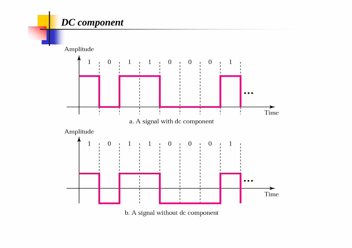
DC component

A signal has two data levels with a pulse duration of 1ms. We calculate the pulse rate and bit rate as follows:Pulse Rate = 1/ 10Pulse Rate = 1/ 10--33= 1000 pulses/s= 1000 pulses/s
Bit Rate = Pulse Rate x logBit Rate = Pulse Rate x log22 L = 1000 x logL = 1000 x log22 2 = 1000 bps2 = 1000 bps
Pulse Rate versus Bit RateBit Rate = Pulse Rate x Log2 L
where L= number of data levels of signals
A signal has four data levels with a pulse duration of 1ms. We calculate the pulse rate and bit rate as follows:
Pulse Rate = 1/ Pulse Rate = 1/ 1010--33 = 1000 pulses/s= 1000 pulses/s
Bit Rate = Bit Rate = PulseRatePulseRate x logx log22 L = 1000 x logL = 1000 x log22 4 = 2000 bps4 = 2000 bps

Lack of synchronization
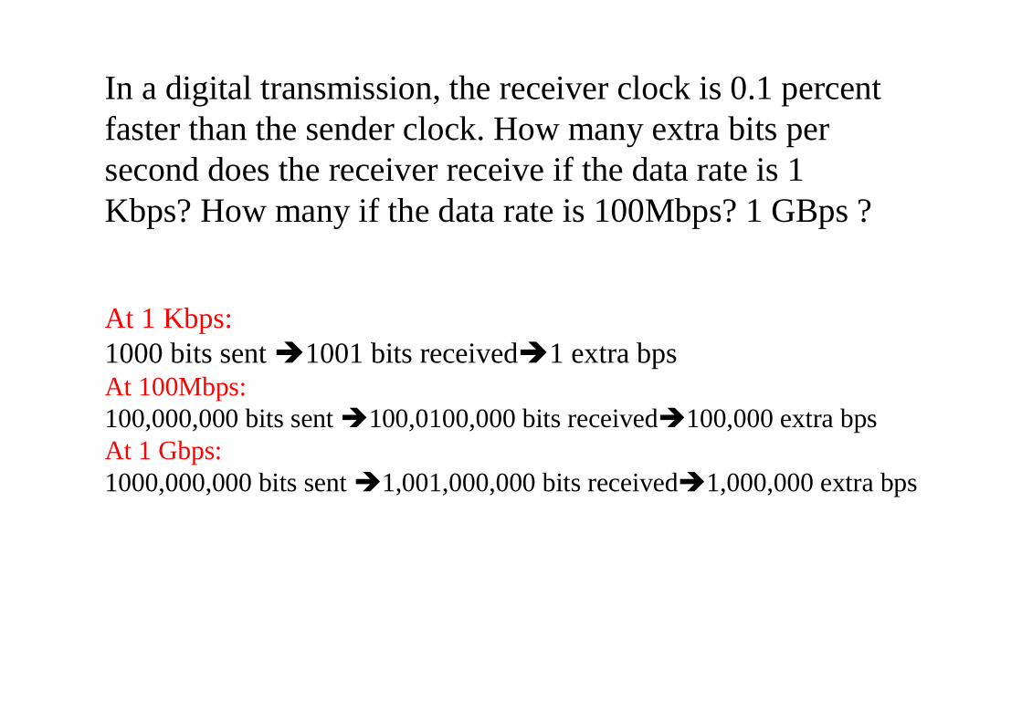
In a digital transmission, the receiver clock is 0.1 percent faster than the sender clock. How many extra bits per second does the receiver receive if the data rate is 1 Kbps? How many if the data rate is 100Mbps? 1 GBps ?
At 1 Kbps:1000 bits sent 1001 bits received1 extra bpsAt 100Mbps:100,000,000 bits sent 100,0100,000 bits received100,000 extra bpsAt 1 Gbps:1000,000,000 bits sent 1,001,000,000 bits received1,000,000 extra bps
Self Synchronization
A self synchronization digital signal includes timing information in the data being transmitted.
This can be achieved if there are transitions in the signal that alert the receiver to the
•beginning,
•middle or
•end of the pulse.
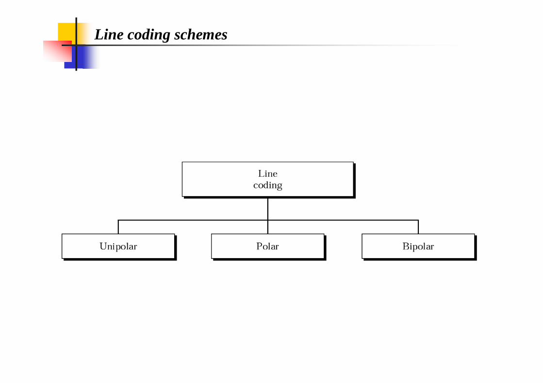
Line coding schemes
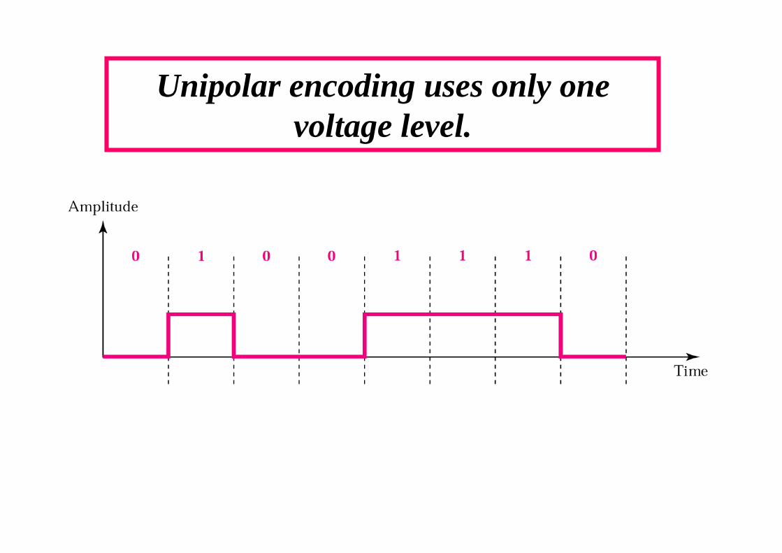
Unipolar encoding uses only one voltage level.
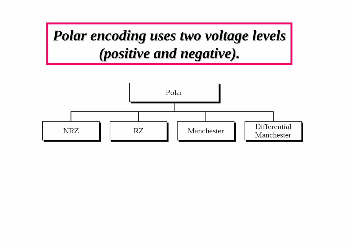
Polar encoding uses two voltage levels Polar encoding uses two voltage levels (positive and negative).(positive and negative).

NRZ-L (Non Return to zero- Level) and NRZ-I (Non Return to zero –Invert encoding
In NRZIn NRZ--I the signal is inverted if a 1 is encountered.I the signal is inverted if a 1 is encountered.
In NRZIn NRZ--L the level of the signal is dependent upon the state of the bitL the level of the signal is dependent upon the state of the bit..
If the original data has a string of consecutive 0 the receiver If the original data has a string of consecutive 0 the receiver can lose its place and cannot do the can lose its place and cannot do the ““galvanic separationgalvanic separation””
0 = positive signal
1 = negative signal
0 = no transition 1 = transition
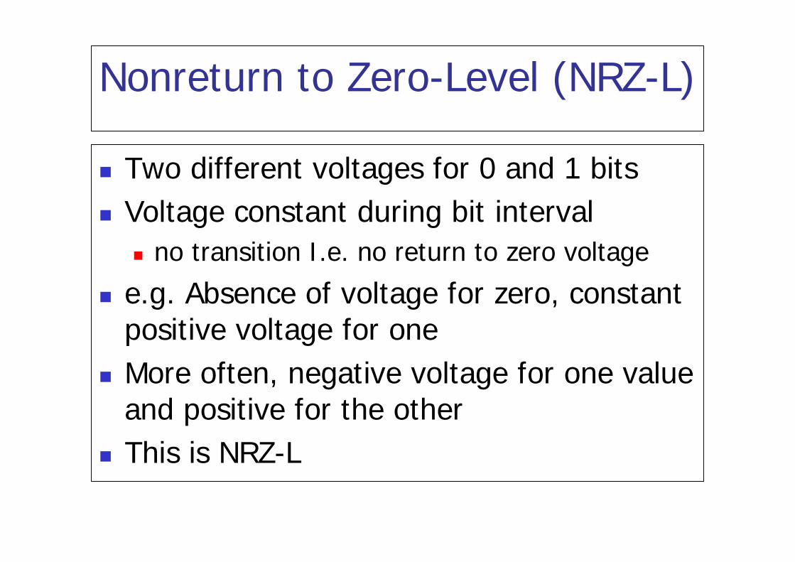
Nonreturn to Zero-Level (NRZ-L)
Two different voltages for 0 and 1 bits Voltage constant during bit interval
no transition I.e. no return to zero voltage
e.g. Absence of voltage for zero, constant positive voltage for one
More often, negative voltage for one value and positive for the other
This is NRZ-L
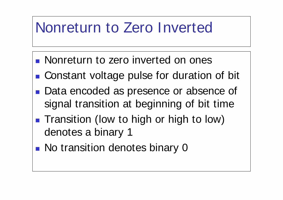
Nonreturn to Zero Inverted
Nonreturn to zero inverted on ones Constant voltage pulse for duration of bit Data encoded as presence or absence of
signal transition at beginning of bit time Transition (low to high or high to low)
denotes a binary 1 No transition denotes binary 0

NRZ pros and cons
Pros Easy to engineer Make good use of bandwidth
Cons dc component Lack of synchronization capability
Used for magnetic recording Not often used for signal transmission

RZ (Return to zero) encoding
RZ uses three values :positive; negative and zero. The signal changes during each bit. Halfway each bit interval the signal return to zero
1 = transition from positive to zero0 = transition from negative to zero
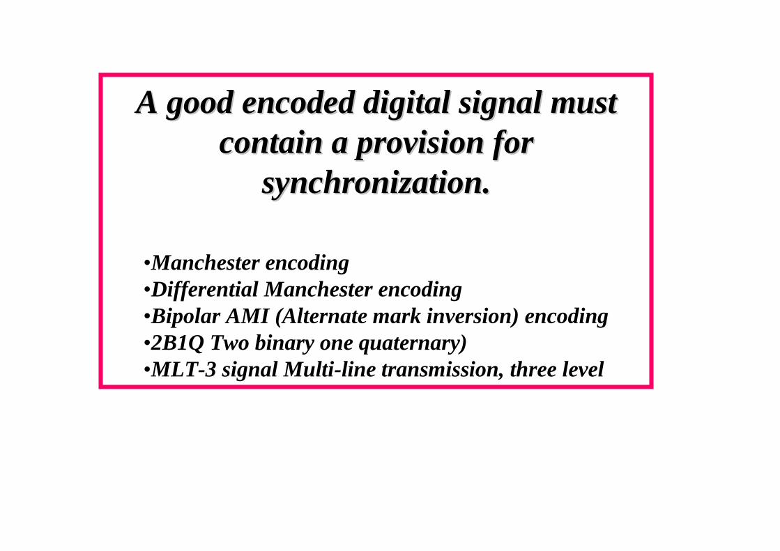
A good encoded digital signal must A good encoded digital signal must contain a provision for contain a provision for
synchronization.synchronization.
•Manchester encoding•Differential Manchester encoding•Bipolar AMI (Alternate mark inversion) encoding•2B1Q Two binary one quaternary)•MLT-3 signal Multi-line transmission, three level
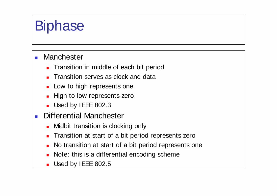
Biphase
Manchester Transition in middle of each bit period Transition serves as clock and data Low to high represents one High to low represents zero Used by IEEE 802.3
Differential Manchester Midbit transition is clocking only Transition at start of a bit period represents zero No transition at start of a bit period represents one Note: this is a differential encoding scheme Used by IEEE 802.5
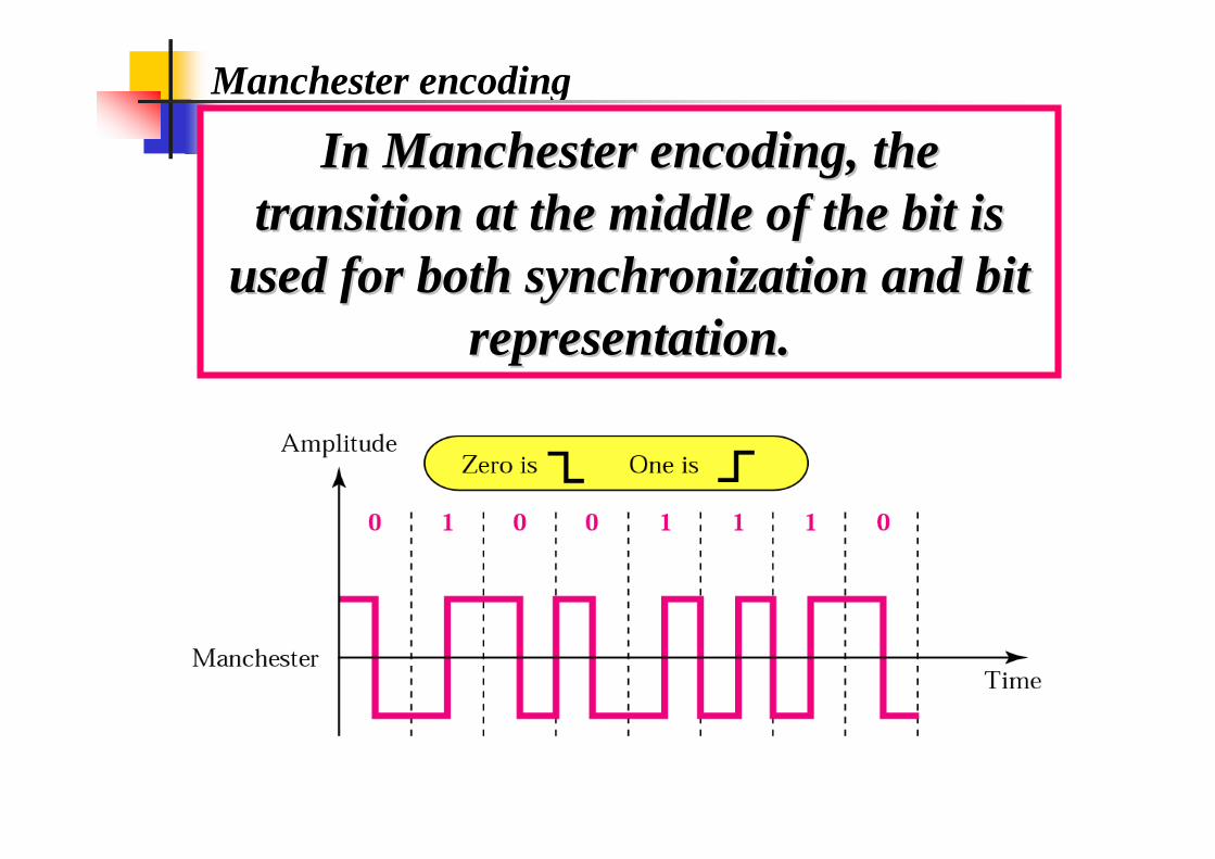
Manchester encoding
In Manchester encoding, the In Manchester encoding, the transition at the middle of the bit is transition at the middle of the bit is
used for both synchronization and bit used for both synchronization and bit representation.representation.
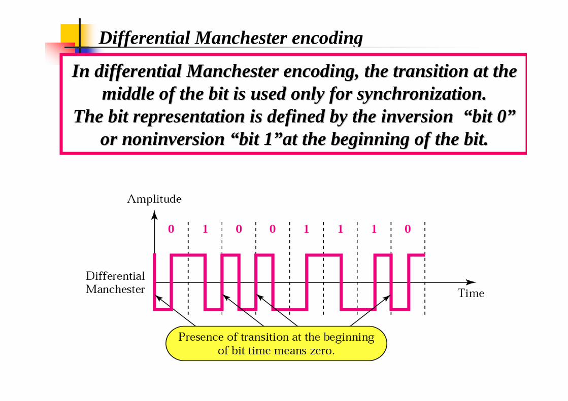
Differential Manchester encoding
In differential Manchester encoding, the transition at the In differential Manchester encoding, the transition at the middle of the bit is used only for synchronization. middle of the bit is used only for synchronization.
The bit representation is defined by the inversion The bit representation is defined by the inversion ““bit 0bit 0””or or noninversionnoninversion ““bit 1bit 1””at the beginning of the bit.at the beginning of the bit.
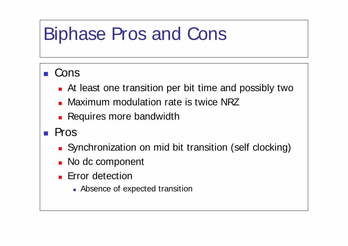
Biphase Pros and Cons
Cons At least one transition per bit time and possibly two Maximum modulation rate is twice NRZ Requires more bandwidth
Pros Synchronization on mid bit transition (self clocking) No dc component Error detection
Absence of expected transition
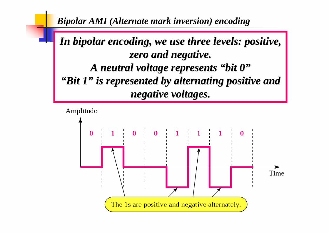
Bipolar AMI (Alternate mark inversion) encoding
In bipolar encoding, we use three levels: positive, In bipolar encoding, we use three levels: positive, zero and negative.zero and negative.
A neutral voltage represents A neutral voltage represents ““bit 0bit 0””““Bit 1Bit 1”” is represented by alternating positive and is represented by alternating positive and
negative voltages.negative voltages.
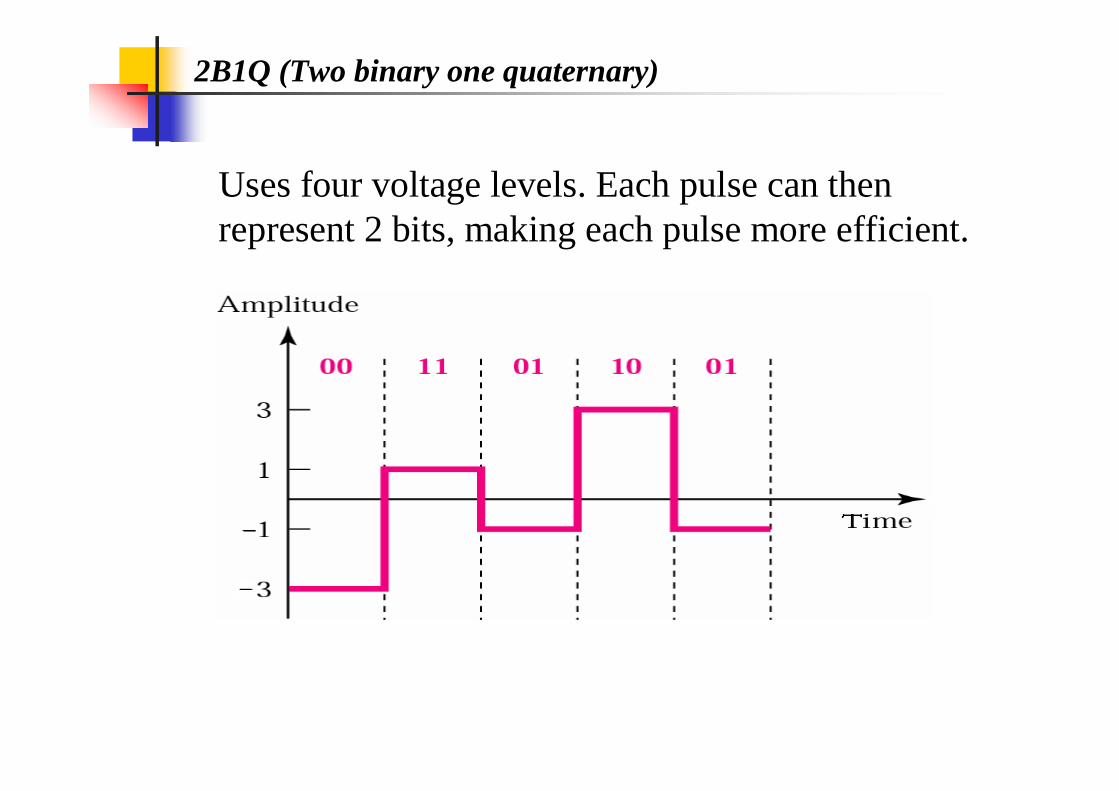
2B1Q (Two binary one quaternary)
Uses four voltage levels. Each pulse can then represent 2 bits, making each pulse more efficient.

MLT-3 signal Multi-line transmission, three level
There is no transition at the beginning of 0 bit, The signal transitions from one level to the next at the beginning of a 1 bit
It is similar to NRZ-I but it uses three levels of signals (+1, 0 and -1)
Block Coding
Steps in Transformation
Some Common Block Codes

Block coding
We need some kind of redundancy to ensure synchronization. We need to include other redundant bits to detect errors. Block coding can achieve these two goals.
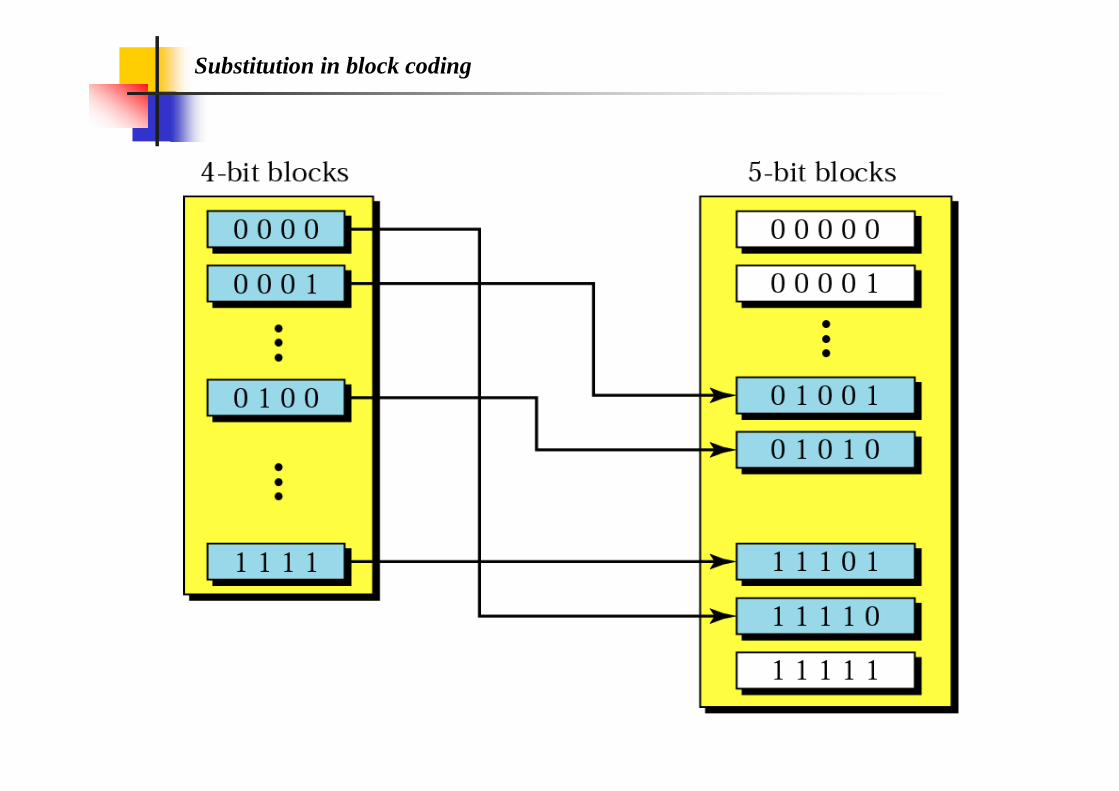
Substitution in block coding
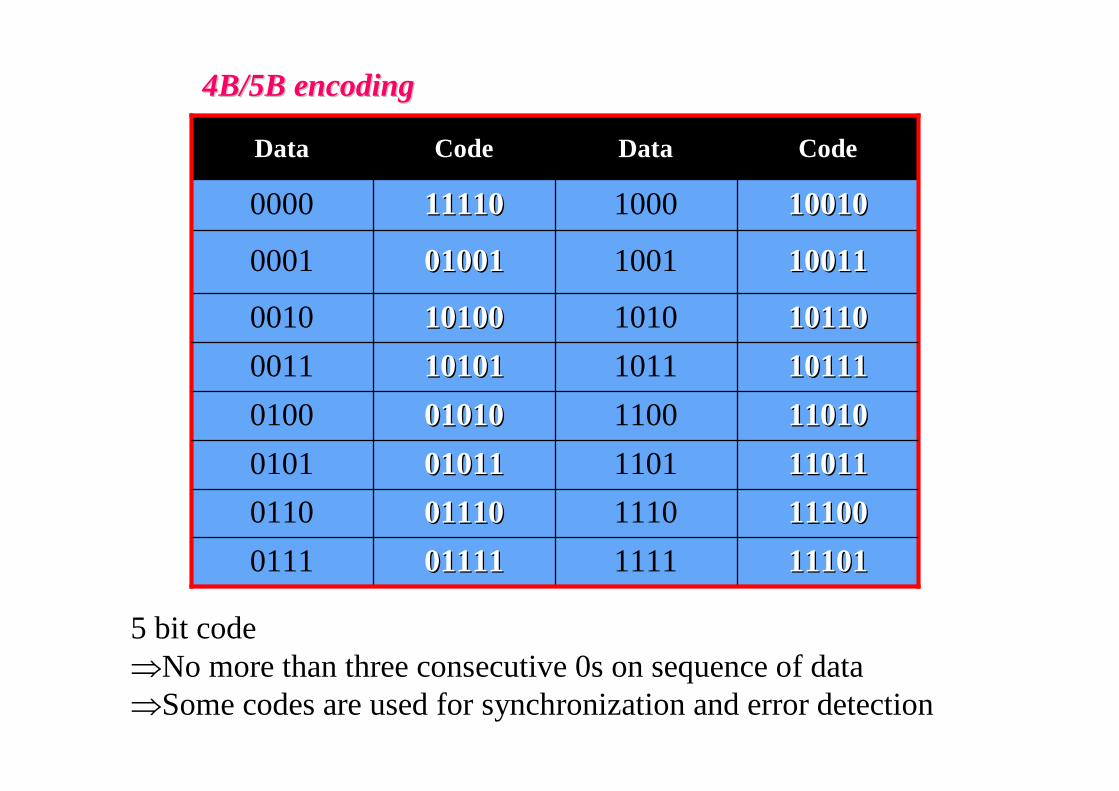
4B/5B encoding4B/5B encoding
1101011010110001010010100100110111101111010101101011010111100111001110011100111001101110111101111101111011110111
10111101111011101011010100111010010100
0100101001
1111011110
Code
101101011010100010
100111001110010001
10010100101000 0000
CodeDataData
5 bit code No more than three consecutive 0s on sequence of dataSome codes are used for synchronization and error detection
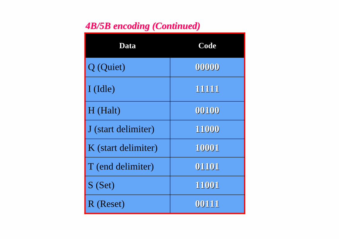
4B/5B encoding (Continued)4B/5B encoding (Continued)
1000110001K (start delimiter)
0110101101T (end delimiter)
1100111001S (Set)
0011100111R (Reset)
1100011000J (start delimiter)
0010000100
1111111111
0000000000
Code
H (Halt)
I (Idle)
Q (Quiet)
Data
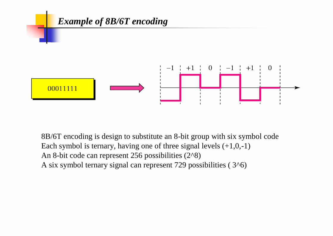
Example of 8B/6T encoding
8B/6T encoding is design to substitute an 8-bit group with six symbol codeEach symbol is ternary, having one of three signal levels (+1,0,-1)An 8-bit code can represent 256 possibilities (2^8) A six symbol ternary signal can represent 729 possibilities ( 3^6)


![CHAPTER-4 Line Codes RZ: Return to Zero [ pulse for half ... · NRZ . Return to Zero[ pulse for full duration of T. b ] Unipolar (NRZ) Unipolar NRZ . NRZ-inverted (differential](https://img.dokumen.tips/doc/110x75/5cc1fa9b88c9933e3a8d2cb0/chapter-4-line-codes-rz-return-to-zero-pulse-for-half-nrz-return-to.jpg)