Embed Size (px)
Citation preview
Rate-Distortion Based Segmentation for MRC Compression
Hui Chenga, Guotong Fengb and Charles A. Boumanb
aSarnoff Corporation, Princeton, NJ 08543-5300, USAbPurdue University, West Lafayette, IN 47907-1285, USA
ABSTRACT
Effective document compression algorithms require scanned document images be first segmented into regionssuch as text, pictures and background. In this paper, we present a document compression algorithm that isbased on the 3-layer (foreground/mask/background) MRC (mixture raster content) model. This compressionalgorithm first segments a scanned document image into different classes. Then, each class is transformed to the3-layer MRC model differently according to the property of that class. Finally, the foreground and the back-ground layers are compressed using JPEG with customized quantization tables. The mask layer is compressedusing JBIG2. The segmentation is optimized in the sense of rate-distortion for the 3-layer MRC representation.It works in a closed loop fashion by applying each transformation to each region of the document and then se-lecting the method that yields the best rate-distortion trade-off. The proposed segmentation algorithm can notonly achieve a better rate-distortion trade-off, but also produce more robust segmentations by eliminating thosemisclassifications which can cause severe artifacts. At similar bit rates, our MRC compression with the rate-distortion based segmentation can achieve a much higher subjective quality than state-of-the-art compressionalgorithms, such as JPEG and JPEG-2000.
Keywords: Segmentation, Document Compression, MRC Compression, Rate-Distortion.
1. INTRODUCTION
To achieve high quality document reproduction and rendering, paper documents must be scanned at a minimumof 400-600 dpi (dots per inch). A single page of a color document scanned at 400-600 dpi requires approximately45-100 Megabytes of storage. Consequently, practical systems for processing color documents require documentcompression methods that achieve high compression ratios with very low distortion.
Since document images contain well defined regions with distinct characteristics, such as text, line graphics,continuous-tone pictures, halftone pictures and background, they are also referred as mixture raster content(MRC). Traditional compression algorithms, such as JPEG, tend to perform poorly on document images,because these algorithms assume that the input image is spatially homogeneous. Therefore, new compressionapproaches need to be developed for MRC applications.
Most existing MRC compression algorithms can be crudely classified as block-based approaches and layer-based approaches. Block-based approaches1–4 segment non-overlapping blocks of pixels into different classes,and compress each class differently according to its characteristics. On the other hand, layer-based approaches5–7
partition a document image into different layers, such as the background layer and the foreground layer. Then,each layer is coded as an image independently from other layers. Most layer-based approaches use the 3-layer (foreground/mask/background) representation proposed in the ITU’s Recommendations T.44 for mixedraster content (MRC). The foreground layer contains the color of text and line graphics, and the backgroundlayer contains pictures and background. The mask is a bi-level image which determines, for each pixel in thereconstructed image, if the foreground color or the background color should be used.
The performance of a document compression system is directly related to the segmentation algorithm usedto produce the binary mask. A good segmentation can not only lower the bit rate, but also lower the distortion.
H. Cheng: E-mail: [email protected], Telephone: 1 (609) 734-2492, Visual Information Systems, Sarnoff Corpo-ration, Princeton, NJ 08543-5300, USAG. Feng and C.A. Bouman: E-mail: {fengg, bouman}@ecn.purdue.edu, School of Electrical and Computer Engineering,Purdue University, West Lafayette, IN 47907-1285, USA
On the other hand, those artifacts which are most damaging are often caused by misclassifications. Somesegmentation algorithms which have been proposed for document compression use features extracted from thediscrete cosine transform (DCT) coefficients to separate text blocks from picture blocks.2, 8 Other segmentationalgorithms are based on the features extracted directly from the input document image.5, 9 However, most ofthese algorithms segment a document image based solely on the document image. They do not consider thecompression algorithms used for each class and the rate-distortion trade-off preferred by a user. Therefore, werefer to these algorithms as direct segmentation algorithms.
One approach to designing a good document coder is to optimized the operational rate-distortion.3, 4, 10 Infact, operational rate-distortion methods have come into wide use for image and video coders.11 In previouswork, de Queiroz applied this technique to finding optimal thresholds for block segmentation.3 Cheng andBouman used the rate-distortion optimization criteria to compute the document segmentation that producedapproximately the best quality/bit rate trade-off for each document begin compressed.4, 10 However, thismethod used a block based method rather than the more standard layer based approach of the MRC standard.
In this paper, we present rate-distortion based segmentation algorithm which supports the standard 3-layerMRC format and is based on conventional JPEG compression for the forground and background layers. Thealgorithm first segments 8 × 8 non-overlapping blocks of pixels into different classes, such as text, picture andbackground. Then, each block is represented differently using a 3-layer MRC model according to the propertyof that class. The 8 × 8 block segmentation is computed by optimizing the actual rate-distortion performancefor the image being coded. It works by first applying each class to each region of the image, and then selectingthe class for each region which approximately maximizes the rate-distortion performance. The optimization isbased on the measured distortion and an estimate of the bit rate for each class. Compared with direct imagesegmentation algorithms, the rate-distortion based segmentation has several advantages. First, it producesmore robust segmentations. Intuitively, misclassifications which cause severe artifacts are eliminated becauseall possible classes are tested for each block of the image. In addition, it allows us to control the trade-offbetween the bit rate and the distortion by adjusting a weight. For each weight set by a user, an approximatelyoptimal segmentation is computed to achieve the best rate-distortion trade-off.
We test our algorithm on both scanned and noiseless synthetic document images. Experimental resultsshow that, in the same range of compression ratios, the 3-layer MRC with using the proposed rate-distortionbased segmentation results in a much higher subjective quality than well-known compression algorithms, suchas JPEG and JPEG-2000, especially in text and graphic regions,
2. 3-LAYER MRC COMPRESSION
As shown in Fig. 1, the 3-layer MRC model represents a document image using three layers: a foreground layer,a background layer and a mask layer. The mask layer is a binary image. It is used to determine, for each pixelin the reconstructed image whether the foreground color or the background color should be used. Let (u, v) bea 2-D vector that defines a pixel location. Denote the foreground as F , the background as B, and the binarymask as M . Then, the image reconstructed from a 3-layer MRC model, G, can be written as
G(u, v) = M(u, v)F (u, v) + (1 − M(u, v))B(u, v)
Ideally, the foreground layer should contain colors of text, and the background layer should contain continuous-tone, halftone pictures and background colors. Therefore, both the foreground and the background layers havesignificant spatially redundancy and can be compressed aggressively. On the other hand, the mask layer containsthe contours of text and other fine image structures. Although the mask layer needs high spatial resolutionto accurately represent text contours and fine image structures, it has only two colors, and can be compressedeffectively using token based compression algorithm, such as JBIG2 [2]. Both the foreground layer and thebackground layer can be compressed using any compression algorithm. However, for real-time copying andscanning applications, we compress both layers using JPEG, but with different quantization tables.
To use a 3-layer MRC model, a document image needs to be first segmented into foreground and background.Since in this paper, JPEG is used to compress both the foreground and the background, the segmentation of

Mixed
ContentRaster
Mixed
ContentRaster
+ +=
Figure 1: Illustration of 3-layer MRC representation.
Document Image
One-color Foreground
Background Block
JPEG
8x8 Block Segmentation
One-colorBackground
ExtractMean Color
Two-color Block
JBIG2/ CCITT4
Bilevel Thresholding
Background Color
Foreground Color
Binary Mask
ExtractMean Color
Foreground Block
Background LayerForeground Layer
JPEG
Mask Layer
Figure 2. Flow diagram of the rate-distortion optimized 3-layer MRC compression system. For example, for a foregroundblock, the corresponding block in the background is set with the mean color of the previous block and the mask block isset to be 1.
the whole image can be simplified to the segmention of pixels into 8 × 8 blocks. For each 8 × 8 block of pixels,there are three possibilities: (1) all pixels belong to the foreground, (2) all pixels belong to the background or(3) some of pixels belong to the foreground and others belong to the background. If all pixels of an 8× 8 blockbelong to foreground, the block is called a Foreground block. If all pixels of an 8×8 block belong to background,the block is called a Background block. If some pixels of the block belong to foreground and others belong tobackground, we call the block a Two-color block. In addition, if a Background block can be represented withonly one color with acceptable distortion, it is called an One-color Background block. If a Foreground blockcan be represented with only one color, it is called an One-color Foreground block.
Two-color blocks are effective in compressing text or line graphics. Text and line graphics need to be codedwith high spatial resolution, but they can tolerate low color resolution. Therefore, for each Two-color block, abilevel thresholding is used to extract two colors (one foreground color and one background color) and a binary
mask. Finally, a Two-color block is represented with a foreground block with a constant color, a backgroundblock with a constant color and a binary 8 × 8 mask.
Background blocks should be from background regions. Blocks of continuous-tone or halftone pictures thatcan code well at the JPEG quality factor used for background are also classified as Background blocks. Thebackground layer is often compressed aggressively with customized quantization tables. If the background isuniform, One-color Background blocks can be used to represent the whole block with only one color, furtherimproving the compression.
However, in order to achieve high quality reconstruction, some “difficult” regions within continuous-tone,halftone pictures and graphics need to be compressed at a higher quality level than what is used for background.Therefore, for foreground, different quantization tables with much lower quantization steps than those used forbackground blocks are used for both luminance and chrominance. Other than the regions that can not becompressed well enough in background layer, foreground also contains colors of text, line art and other detaileddocument regions. However, the color of text and line art is often similar over large scale. Therefore, they havefew high frequency components, and can be compressed with lower quantization steps without significantlyincreasing the bit rate of the foreground.
The details of compression of each of these five classes are described in the following subsections. The flowdiagram of our compression algorithm is shown in Fig. 2. Throughout this paper, we use y to denote theoriginal image and x to denote its 8× 8 block segmentation. Also, yi denotes the i-th 8× 8 block in the image,where the blocks are taken in raster order, and xi denotes the class label of block i, where 0 ≤ i < L, andL is the total number of blocks. The set of class labels is then N = {Two, OnB, OnF, Fgd, Bgd}, whereTwo, OnB, OnF, Fgd, Bgd represent Two-color, One-color Background, One-color Foreground, Foregroundand Background blocks, respectively.
2.1. MRC Representation of One-color Background and One-color Foreground Blocks
Each One-color Background block and One-color Foreground block is represented by a 24-bit color. For One-color Background blocks, we first extract the mean color of each block. Then, set all pixels of the correspondingblock in the background layer with the mean color, and set all pixels of the corresponding block in the foregroundlayer with the mean color of the previous block in raster order. The corresponding block in the mask layer isset to 0 indicating that the whole block belongs to the background layer.
Similarly, we set all pixels of One-color Foreground blocks in the foreground layer to the mean colors of thecorresponding blocks in the original image, and set all pixels of One-color Foreground blocks in the backgroundlayer with the mean color of the previous block in raster order. The corresponding block in the mask layer isset to 1 since the whole block belongs to the foreground layer.
2.2. MRC Representation of Two-color Blocks
The Two-color class is designed to compress blocks which can be represented well by two colors, such astext blocks. Since Two-color blocks need to be coded with high spatial resolution, but can tolerate low colorresolution, each Two-color block is represented by two 24-bit colors and a binary mask. The bilevel thresholdingalgorithm that we use for extracting the two colors and the binary mask uses a minimal mean squared error(MSE) thresholding followed by a spatially adaptive refinement. The algorithm is performed on two block sizes.First, 8 × 8 blocks are used. But sometimes an 8 × 8 block may not contain enough samples from both colorregions for a reliable estimate of the colors of both regions and the binary mask. In that case, a 16 × 16 blockcentered at the 8 × 8 block will be used instead.
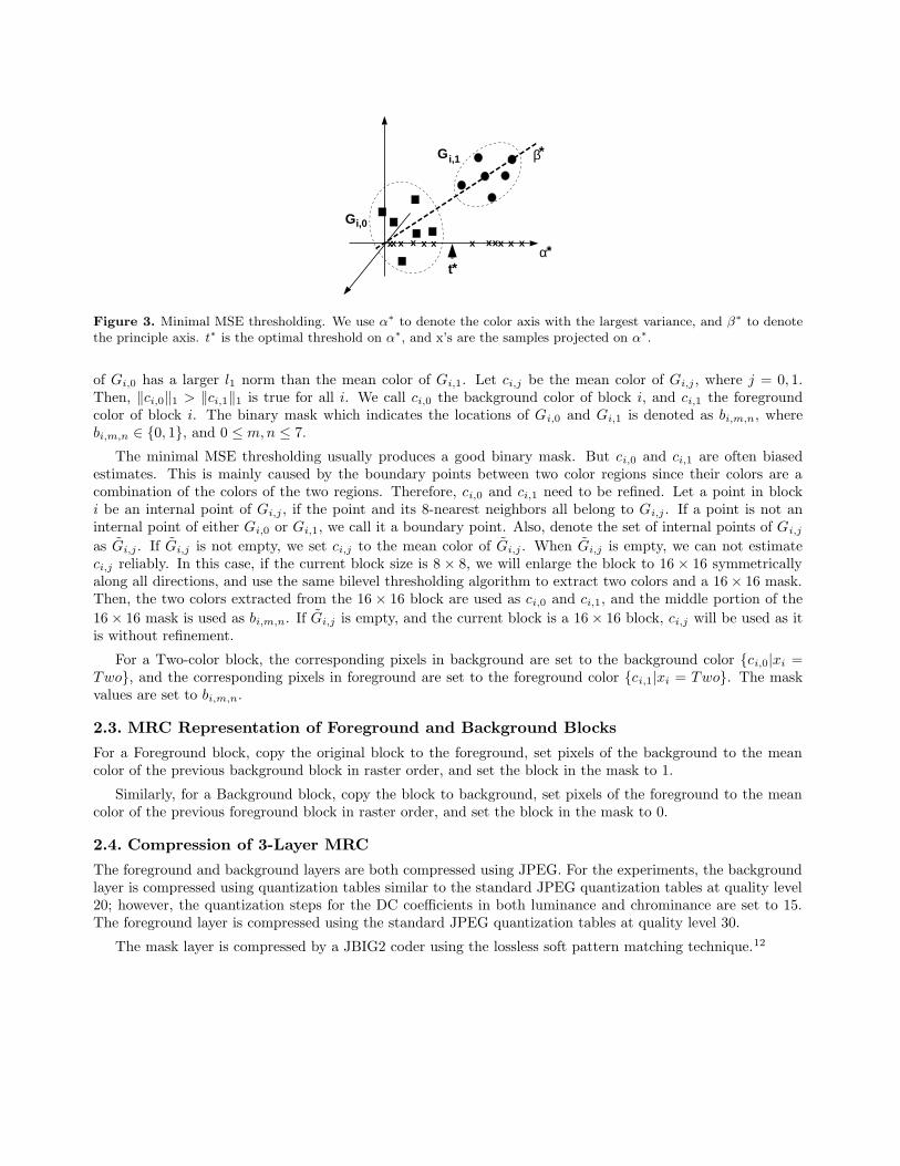
The minimal MSE thresholding algorithm is illustrated in Fig. 3. For a Two-color block yi, we first projectall colors of yi onto the color axis α∗ which has the largest variance among three color axes. The thresholdingis done only on α∗. Since we are mainly interested in high quality document images where text is sharp and thenoise level is low, the projection step significantly lowers the computation complexity without sacrificing thequality of the bilevel thresholding. For a threshold t on α∗, t partitions all colors into two groups. Let Ei(t) bethe MSE, when colors in each group are represented by the mean color of that group. We compute the valuet∗ which minimizes Ei(t). Then, t∗ partitions the block into two groups, Gi,0 and Gi,1, where the mean color
xx xxx xxxxxx x
t*α*
β*
Gi,0
G i,1
Figure 3. Minimal MSE thresholding. We use α∗ to denote the color axis with the largest variance, and β∗ to denotethe principle axis. t∗ is the optimal threshold on α∗, and x’s are the samples projected on α∗.
of Gi,0 has a larger l1 norm than the mean color of Gi,1. Let ci,j be the mean color of Gi,j , where j = 0, 1.Then, ‖ci,0‖1 > ‖ci,1‖1 is true for all i. We call ci,0 the background color of block i, and ci,1 the foregroundcolor of block i. The binary mask which indicates the locations of Gi,0 and Gi,1 is denoted as bi,m,n, wherebi,m,n ∈ {0, 1}, and 0 ≤ m,n ≤ 7.
The minimal MSE thresholding usually produces a good binary mask. But ci,0 and ci,1 are often biasedestimates. This is mainly caused by the boundary points between two color regions since their colors are acombination of the colors of the two regions. Therefore, ci,0 and ci,1 need to be refined. Let a point in blocki be an internal point of Gi,j , if the point and its 8-nearest neighbors all belong to Gi,j . If a point is not aninternal point of either Gi,0 or Gi,1, we call it a boundary point. Also, denote the set of internal points of Gi,j
as G̃i,j . If G̃i,j is not empty, we set ci,j to the mean color of G̃i,j . When G̃i,j is empty, we can not estimateci,j reliably. In this case, if the current block size is 8 × 8, we will enlarge the block to 16 × 16 symmetricallyalong all directions, and use the same bilevel thresholding algorithm to extract two colors and a 16 × 16 mask.Then, the two colors extracted from the 16 × 16 block are used as ci,0 and ci,1, and the middle portion of the
16 × 16 mask is used as bi,m,n. If G̃i,j is empty, and the current block is a 16 × 16 block, ci,j will be used as itis without refinement.
For a Two-color block, the corresponding pixels in background are set to the background color {ci,0|xi =Two}, and the corresponding pixels in foreground are set to the foreground color {ci,1|xi = Two}. The maskvalues are set to bi,m,n.
2.3. MRC Representation of Foreground and Background Blocks
For a Foreground block, copy the original block to the foreground, set pixels of the background to the meancolor of the previous background block in raster order, and set the block in the mask to 1.
Similarly, for a Background block, copy the block to background, set pixels of the foreground to the meancolor of the previous foreground block in raster order, and set the block in the mask to 0.
2.4. Compression of 3-Layer MRC
The foreground and background layers are both compressed using JPEG. For the experiments, the backgroundlayer is compressed using quantization tables similar to the standard JPEG quantization tables at quality level20; however, the quantization steps for the DC coefficients in both luminance and chrominance are set to 15.The foreground layer is compressed using the standard JPEG quantization tables at quality level 30.
The mask layer is compressed by a JBIG2 coder using the lossless soft pattern matching technique.12
3. RATE DISTORTION BASED SEGMENTATION FOR MRC
In order to segment each 8 × 8 block of pixels into the five classes discussed in section 2, we propose a rate-distortion optimized segmentation. A number of segmentation algorithms have been proposed to segment adocument image into foreground and background.2, 3, 5, 8–10 Most of these algorithms are direct segmentationalgorithms. Direct segmentation algorithms segment a document image based solely on the document image.In contrast, the rate-distortion based method works in a closed loop fashion by applying each coding method toeach region of the document and then selecting the method that yields the best rate-distortion trade-off. Therate-distortion based method insures that each block is coded using the method which is best suited for it. Thisresults in more robust segmentations which yield a better rate-distortion trade-off at every quality level. Therate-distortion approach proposed in this paper is closely related to the approach introduced in.10 However, theprevious approach is designed for a block based document compression system called the multilayer compressionsystem, not the 3-layer MRC representation.
Let R(y|x) be the number of bits required to code y with block segmentation x, and D(y|x) be the totaldistortion resulting from coding y with segmentation x. Then, the rate-distortion based segmentation, x∗, is
x∗ = arg minx∈NL
{R(y|x) + λD(y|x)} , (1)
where λ is a non-negative real number which controls the trade-off between bit rate and distortion. In ourapproach, we assume that λ is a constant controlled by a user which has the same function as the qualitylevel in JPEG. In addition, since the segmentation is only used to guide the compression and not used in thereconstruction. The block segmentation map does not need to be sent to the decoder. Therefore, no bits arerequired for the segmentation map.
To compute the rate-distortion based segmentation, we need to estimate the number of bits required forcoding each block as each class, and the distortion of coding each block as each class. For computationalefficiency, we assume that the number of bits required for coding a block only depends on the image data andclass labels of that block and the previous block in raster order. We also assume that the distortion of a blockcan be computed independently from other blocks. With these assumptions, (1) can be rewritten as
x∗ = arg min{x0,x1,...,xL−1}∈NL
L−1∑
i=0
{Ri(xi|xi−1) + λDi(xi)} , (2)
where Ri(xi|xi−1) is the number of bits required to code block i using class xi given xi−1, and Di(xi) is thedistortion produced by coding block i as class xi. After the rate and distortion are estimated for each blockusing each coder, (2) can be solved by a dynamic programming technique similar to that used in.13
An important aspect of our approach is that we use a class-dependent distortion measure. This is desirablebecause, for document images, different regions, such as text, background and pictures, can tolerate differenttypes of distortion. For example, errors in high frequency bands are less important in background and pictureregions, but they can cause severe artifacts in text regions.
In the following sections, we specify how to compute the rate and distortion terms for the 3-layer MRC model.The expressions for rate are often approximate due to the difficulties of accurately modeling high performancecoding methods such as JBIG2. However, our experimental results indicate that these approximations areaccurate enough to consistently achieve good compression results.
3.1. Bit Rate Estimate
Although the five different classes, (Two,OnB,OnF, Fgd,Bgd), are transformed to the 3-layer MRC modeldifferently, they are all represented by one 8 × 8 block in the foreground, one block in the background and onein the mask layer. Therefore, the number of bits required for coding any block consists of the number of bitsrequired for the foreground, the number of bits for the background and the number of bits for the mask.

The bits required for coding either foreground or background block i can be further divided into two parts:the bits required for coding the luminance of block i, denoted as Rl
i(xi|xi−1), and the bits for coding thechrominance, denoted as Rc
i (xi|xi−1). Therefore,
Ri(xi|xi−1) = Rli(xi|xi−1) + Rc
i (xi|xi−1).
Let αdi (xi) be the quantized DC coefficients of the luminance using the quantization table specified by class xi,
and αai (xi) be the vector which contains all 63 quantized AC coefficients of the luminance of block i. Using the
standard JPEG Huffman tables for luminance, Rli(xi|xi−1) can be computed as
Rli(xi|xi−1) = rd
[
αdi (xi) − αd
i−1(xi−1)]
+ ra [αai (xi)] ,
where rd[·] is the number of bits used for coding the difference between two consecutive DC coefficients ofthe luminance component, and ra[·] is the number of bits used for coding AC coefficients. The formula forcalculating rd[·] and ra[·] is specified in the JPEG standard.14 Notice that Ri(xi|xi−1) is the exact number ofbits required for coding the luminance component using JPEG.
Since the two chrominance components are subsampled 2× 2, we approximate the number of bits for codingthe chrominance components of an 8×8 block i, Rc
i (xi|xi−1), as follows. Let j be the index of the 16×16 blockwhich contains block i. Also, let βd
j,k(zj) be the quantized DC coefficient of the k-th chrominance componentusing the chrominance quantization table of class zj , and βa
j,k(zj) be the vector of the quantized AC coefficients.Then, we assume that
Rci (xi|xi−1) =
1
4
1∑
k=0
{
r′d[
βdj,k(xi) − βd
j−1,k(xi−1)]
+ r′a[
βaj,k(xi)
]}
,
where r′d(·) is the number of bits used for coding the difference between two consecutive DC coefficients of thechrominance components, and r′a(·) is the number of bits used for coding AC coefficients of the chrominancecomponents. Notice that we split the bits used for coding the chrominance equally among the four corresponding8 × 8 blocks of the input document image.
The bits used for coding the mask are approximated by the entropy of a non-parametric conditional proba-bility mass function. Assume that the number of bits for coding bi,m,n only depends on its four causal neighbors,denoted as Vi,m,n = [bi,m−1,n−1, bi,m−1,n, bi,m−1,n+1, bi,m,n−1]
t. Define bi,m,n to be 0, if m < 0 or n < 0 or m > 7or n > 7. Then, the number of bits required to code the binary mask is approximated as
−7
∑
m=0
7∑
n=0
log2 pb(bi,m,n|Vi,m,n),
where pb(bi,m,n|Vi,m,n) is the transition probability from the four causal neighbors to pixel (m,n) in block i.
3.1.1. Distortion
For the four classes (except Two-color blocks): One-color Background, One-color Foreground, Foreground andBackground blocks, the total squared error in YCrCb color space is used as the distortion measure. Thedistortion is computed in the DCT domain, eliminating the need to compute inverse DCT’s. Let el
i(xi) be thequantization error of luminance DCT coefficients of block i using the luminance quantization table of xi, andecj,k(zj) be the quantization error of DCT coefficients of the k-th chrominance component of the 16 × 16 block
containing block i using the chrominance quantization table of zj . Then, the distortion is approximately givenby
Di(xi) =∥
∥eli(xi)
∥
∥
2+
1∑
k=0
∥
∥ecj,k(xi)
∥
∥
2.
Here, we approximate the distortion due to the chrominance channels by dividing the chrominance error amongthe four corresponding 8 × 8 blocks of the luminance channel.

G0
G1
γ
c
c0
c1
d
~
~
Figure 4. Two-color distortion measure. c̃0 and c̃1 are indexed mean colors of group G0 and G1, respectively. γ is theline determined by c̃0 and c̃1. The distance between a color c and γ is d. When c is a combination of c̃0 and c̃1, d = 0.
However, the distortion measure for Two-color blocks is different from the other four classes. Its distortionmeasure is designed with the following considerations. In a scanned image, pixels on the boundary of two colorregions tend to have a color which is a combination of the colors of both regions. Since only two colors are usedfor the block, the boundaries between the color regions are usually sharpened. Although the sharpening generallyimproves the quality, it gives a large difference in pixel values between the original and the reconstructed imageson boundary points. On the other hand, if a block is not a Two-color block, a third color often appears on theboundary. Therefore, a desired distortion measure for Two-color coder should not excessively penalize the errorcaused by sharpening, but should produce a high distortion value, if more than two colors exist. Also, desirableTwo-color blocks should have a certain proportion of internal points. If a Two-color block has very few internalpoints, the block usually comes from background or halftone background, and it can not be a Two-color block.To handle this case, we set the cost to the maximal cost, if the number of internal points is less than or equals to8. The distortion measure for the Two-color block is defined as follows. Define Ii,m,n as an indicator function.Ii,m,n = 1, if (m,n) is an internal point. Ii,m,n = 0, if (m,n) is a boundary point. If xi = Two,
Di(xi) =
7∑
m=0
7∑
n=0
[
Ii,m,n‖yi,m,n − c̃i,bi,m,n‖2 + (1 − Ii,m,n)d2(yi,m,n; c̃i,0, c̃i,1)
]
, if
1∑
j=0
|G̃i,j | > 8
2552 × 64 × 3, if
1∑
j=0
|G̃i,j | ≤ 8
where |G̃i,j | is the number of elements in the set G̃i,j , and d(yi,m,n; c̃i,0, c̃i,1) is the distance between yi,m,n andthe line determined by c̃i,0 and c̃i,1. As illustrated in Fig. 4, if a color c is a combination of c1 and c2, c willbe on the line determined by c1 and c2, d(c; c1, c2) = 0. Therefore, for boundary points of Two-color blocks,d(yi,m,n; c̃i,0, c̃i,1) is small. However, if a third color does exist on a boundary point, d(yi,m,n; c̃i,0, c̃i,1) tends tobe large.
4. EXPERIMENTAL RESULTS
For our experiments, we use an image database consisting of 30 scanned and one synthetic document image.The scanned documents come from a variety of sources, including ASEE Prism and IEEE Spectrum. Thesedocuments are scanned at 400 dpi and 24 bits per pixel (bpp) using the HP flat-bed scanner, scanjet 6100C.A large portion of the 30 scanned images contain halftone background and have ghosting artifacts caused byprinting on the reverse side of the page. These images are used without pre-processing. The synthetic imageshown in Fig. 5(a) ∗ has a complex layout structure and many colors. It is used to test the ability of acompression algorithm to handle complex document images.
∗To obtain color version of the experimental results, please visit http://dynamo.ecn.purdue.edu/ bouman/publicationsor visit http://min.ecn.purdue.edu/ hui.
(a) (b)
(c) (d)
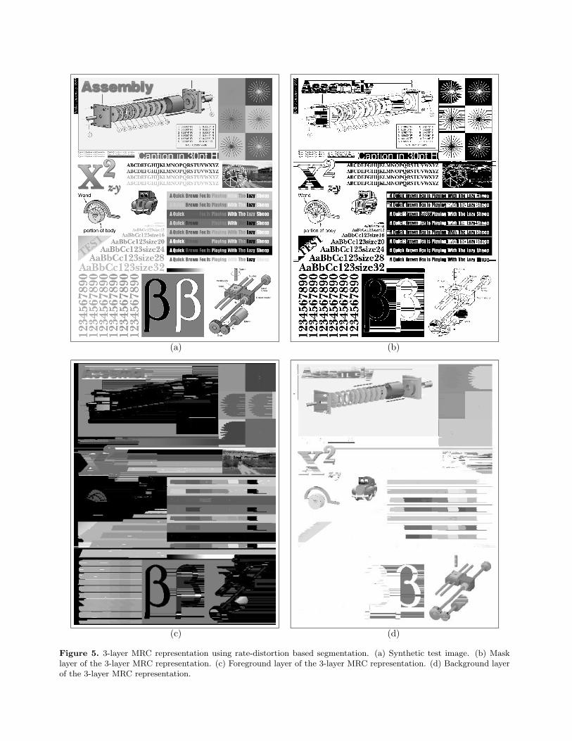
Figure 5. 3-layer MRC representation using rate-distortion based segmentation. (a) Synthetic test image. (b) Masklayer of the 3-layer MRC representation. (c) Foreground layer of the 3-layer MRC representation. (d) Background layerof the 3-layer MRC representation.
(a) (b) (c)
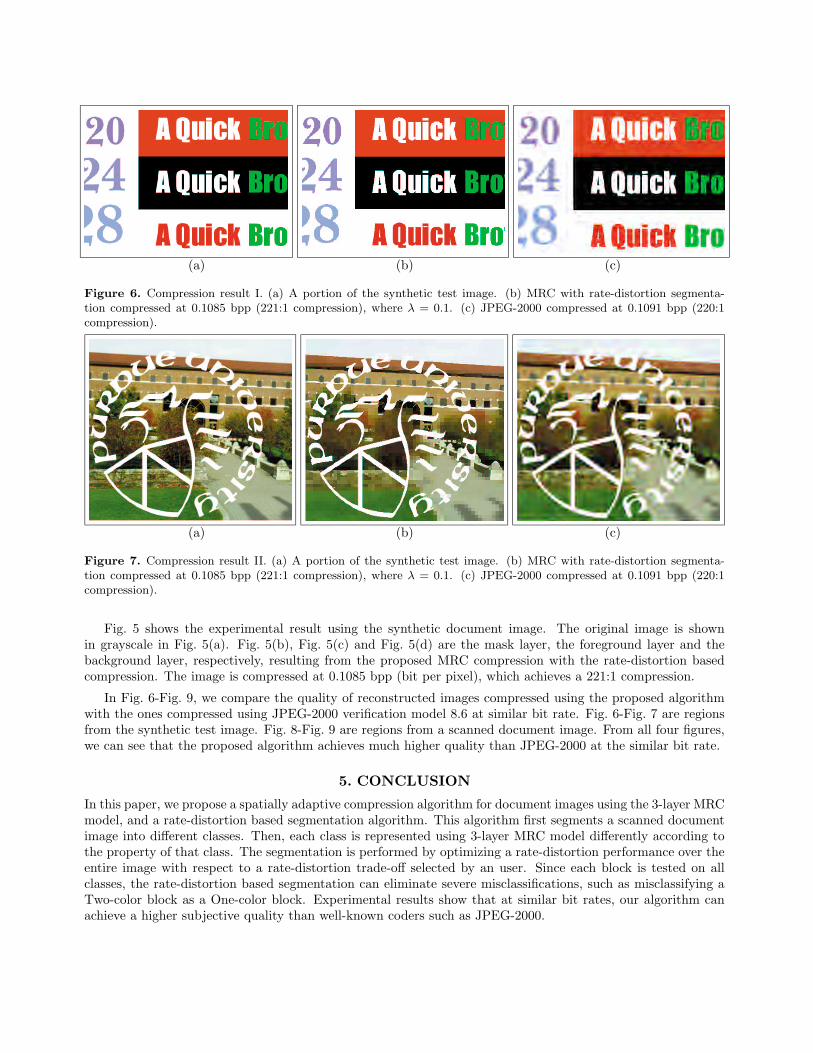
Figure 6. Compression result I. (a) A portion of the synthetic test image. (b) MRC with rate-distortion segmenta-tion compressed at 0.1085 bpp (221:1 compression), where λ = 0.1. (c) JPEG-2000 compressed at 0.1091 bpp (220:1compression).
(a) (b) (c)
Figure 7. Compression result II. (a) A portion of the synthetic test image. (b) MRC with rate-distortion segmenta-tion compressed at 0.1085 bpp (221:1 compression), where λ = 0.1. (c) JPEG-2000 compressed at 0.1091 bpp (220:1compression).
Fig. 5 shows the experimental result using the synthetic document image. The original image is shownin grayscale in Fig. 5(a). Fig. 5(b), Fig. 5(c) and Fig. 5(d) are the mask layer, the foreground layer and thebackground layer, respectively, resulting from the proposed MRC compression with the rate-distortion basedcompression. The image is compressed at 0.1085 bpp (bit per pixel), which achieves a 221:1 compression.
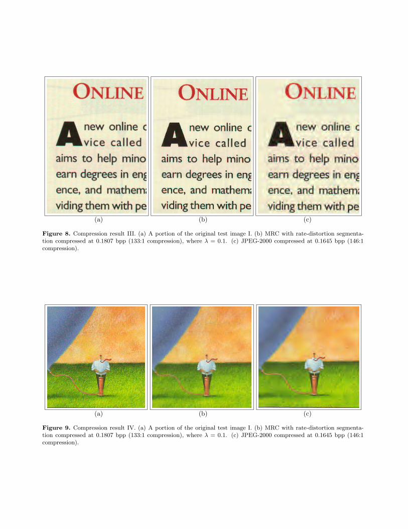
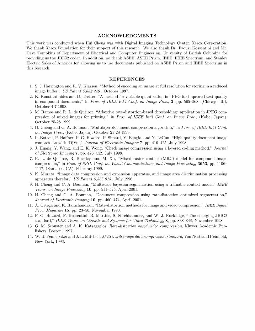
In Fig. 6-Fig. 9, we compare the quality of reconstructed images compressed using the proposed algorithmwith the ones compressed using JPEG-2000 verification model 8.6 at similar bit rate. Fig. 6-Fig. 7 are regionsfrom the synthetic test image. Fig. 8-Fig. 9 are regions from a scanned document image. From all four figures,we can see that the proposed algorithm achieves much higher quality than JPEG-2000 at the similar bit rate.
5. CONCLUSION
In this paper, we propose a spatially adaptive compression algorithm for document images using the 3-layer MRCmodel, and a rate-distortion based segmentation algorithm. This algorithm first segments a scanned documentimage into different classes. Then, each class is represented using 3-layer MRC model differently according tothe property of that class. The segmentation is performed by optimizing a rate-distortion performance over theentire image with respect to a rate-distortion trade-off selected by an user. Since each block is tested on allclasses, the rate-distortion based segmentation can eliminate severe misclassifications, such as misclassifying aTwo-color block as a One-color block. Experimental results show that at similar bit rates, our algorithm canachieve a higher subjective quality than well-known coders such as JPEG-2000.
(a) (b) (c)
Figure 8. Compression result III. (a) A portion of the original test image I. (b) MRC with rate-distortion segmenta-tion compressed at 0.1807 bpp (133:1 compression), where λ = 0.1. (c) JPEG-2000 compressed at 0.1645 bpp (146:1compression).
(a) (b) (c)
Figure 9. Compression result IV. (a) A portion of the original test image I. (b) MRC with rate-distortion segmenta-tion compressed at 0.1807 bpp (133:1 compression), where λ = 0.1. (c) JPEG-2000 compressed at 0.1645 bpp (146:1compression).
ACKNOWLEDGMENTS
This work was conducted when Hui Cheng was with Digital Imaging Technology Center, Xerox Corporation.We thank Xerox Foundation for their support of this research. We also thank Dr. Faouzi Kossentini and Mr.Dave Tompkins of Department of Electrical and Computer Engineering, University of British Columbia forproviding us the JBIG2 coder. In addition, we thank ASEE, ASEE Prism, IEEE, IEEE Spectrum, and StanleyElectric Sales of America for allowing us to use documents published on ASEE Prism and IEEE Spectrum inthis research.
REFERENCES
1. S. J. Harrington and R. V. Klassen, “Method of encoding an image at full resolution for storing in a reducedimage buffer,” US Patent 5,682,249 , October 1997.
2. K. Konstantinides and D. Tretter, “A method for variable quantization in JPEG for improved text qualityin compound documents,” in Proc. of IEEE Int’l Conf. on Image Proc., 2, pp. 565–568, (Chicago, IL),October 4-7 1998.
3. M. Ramos and R. L. de Queiroz, “Adaptive rate-distortion-based thresholding: application in JPEG com-pression of mixed images for printing,” in Proc. of IEEE Int’l Conf. on Image Proc., (Kobe, Japan),October 25-28 1999.
4. H. Cheng and C. A. Bouman, “Multilayer document compression algorithm,” in Proc. of IEEE Int’l Conf.
on Image Proc., (Kobe, Japan), October 25-28 1999.
5. L. Bottou, P. Haffner, P. G. Howard, P. Simard, Y. Bengio, and Y. LeCun, “High quality document imagecompression with ‘DjVu’,” Journal of Electronic Imaging 7, pp. 410–425, July 1998.
6. J. Huang, Y. Wang, and E. K. Wong, “Check image compression using a layered coding method,” Journal
of Electronic Imaging 7, pp. 426–442, July 1998.
7. R. L. de Queiroz, R. Buckley, and M. Xu, “Mixed raster content (MRC) model for compound imagecompression,” in Proc. of SPIE Conf. on Visual Communications and Image Processing, 3653, pp. 1106–1117, (San Jose, CA), Februray 1999.
8. K. Murata, “Image data compression and expansion apparatus, and image area discrimination processingapparatus therefor,” US Patent 5,535,013 , July 1996.
9. H. Cheng and C. A. Bouman, “Multiscale bayesian segmentation using a trainable context model,” IEEE
Trans. on Image Processing 10, pp. 511–525, April 2001.
10. H. Cheng and C. A. Bouman, “Document compression using rate-distortion optimized segmentation,”Journal of Electronic Imaging 10, pp. 460–474, April 2001.
11. A. Ortega and K. Ramchandran, “Rate-distortion methods for image and video compression,” IEEE Signal
Proc. Magazine 15, pp. 23–50, November 1998.
12. P. G. Howard, F. Kossentini, B. Martins, S. Forchhammer, and W. J. Rucklidge, “The emerging JBIG2standard,” IEEE Trans. on Circuits and Systems for Video Technology 8, pp. 838–848, November 1998.
13. G. M. Schuster and A. K. Katsaggelos, Rate-distortion based video compression, Kluwer Academic Pub-lishers, Boston, 1997.
14. W. B. Pennebaker and J. L. Mitchell, JPEG: still image data compression standard, Van Nostrand Reinhold,New York, 1993.