Embed Size (px)
Citation preview
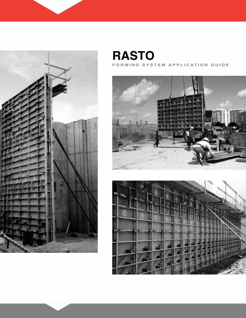
RAStoF o R m i n g S y S t e m A p p l i c At i o n g u i d e

Table of ContentsI System Features ..................................................................................................................................1
A Modular Versatility .........................................................................................................................1B System Strength ............................................................................................................................1
II Basic Equipment ..................................................................................................................................2A Panels .............................................................................................................................................2B Corners ...........................................................................................................................................3C Panel Accessories .........................................................................................................................3D Connecting Components ..............................................................................................................4E Walers .............................................................................................................................................5F Ties and Hardware .........................................................................................................................5G Lifting Brackets .............................................................................................................................6H Core Forming Accessories ...........................................................................................................6I Fall Protection ................................................................................................................................6J Form Alignment and Attachments ...............................................................................................7
III Planning and Assembly Preparations ................................................................................................8IV Erection, Stripping, Panel Connections, and Tie Arrangements ....................................................8
A Arrangement of RASTO Clamps and Wall Ties .....................................................................9B Arrangement of Clamps and Ties for Giant Panels ..................................................................10C Erecting Tall Gangs .....................................................................................................................11
V Corners ...............................................................................................................................................12VI Typical Wall Details ............................................................................................................................14
A 90° Corners ..................................................................................................................................14B T-Wall Intersections .....................................................................................................................14C Pilasters ........................................................................................................................................14
VII Non-Perpendicular Corners ..............................................................................................................15A Hinged Corners ............................................................................................................................15B Application of Hinged Corners ...................................................................................................15
VIII Fillers...................................................................................................................................................16A Fillers with Tension Bolts ............................................................................................................16B Fillers with Adjustable Clamp.....................................................................................................16C Fillers with Walers ........................................................................................................................16D Transition Fillers ..........................................................................................................................16
IX Height Adjustments ...........................................................................................................................17A Adjustments with Panels ............................................................................................................17B Extensions Using Plywood .........................................................................................................17
X Bulkheads ...........................................................................................................................................18XI Columns ..............................................................................................................................................19
A Columns with Outside Corner Clamps ......................................................................................19B Columns with Outside Conversion Corners ............................................................................19C Bolt and Clamp Placement .........................................................................................................21D Hinged Columns ..........................................................................................................................22
XII RASTO Fall Protection .................................................................................................................23A Walkway Brackets .......................................................................................................................23B Other Safety Notes ......................................................................................................................23
XIII Aligning Formwork ............................................................................................................................24A Adjusting Brace ...........................................................................................................................24B Standard Post Shores .................................................................................................................24
XIV Other Tying Considerations ..............................................................................................................25A Foundation Formwork .................................................................................................................25B Battered Walls ..............................................................................................................................25C Taper Ties and She Bolts ............................................................................................................25
XV Crane Lifting of Gang Assemblies ...................................................................................................26A Gangs with Standard Panels ......................................................................................................26B Gangs with Giant Panels.............................................................................................................27
XVI Core Forming .....................................................................................................................................27Product Codes ..........................................................................................................................................28Index ..........................................................................................................................................................29

Metric to U.S. (Imperial) Conversions
Metric U.S. Nearest Dim. (cm) Dim. (in.) 1∕8" 5 1.97 2 10 3.94 4 15 5.91 57∕8 20 7.87 71∕8 30 11.18 11¾ 45 17.72 17¾ 50 19.69 19¾ 55 21.65 215∕8 60 23.62 235∕8 65 25.59 255∕8 70 27.56 27½ 75 29.53 29½ 80 31.50 31½ 90 35.43 353∕8 100 39.37 393∕8 120 47.24 47¼ 150 59.06 59 180 70.87 707∕8 200 78.74 78¾ 240 94.49 94½ 270 106.30 106¼ 300 118.11 1181∕8

RASTO ApplicationGuide 1
I. System FeaturesThe RASTO concreteformingsystemisamodularsystemwhichmaybeused inhandsetorgangformapplications.
A. Modular VersatilityPanelscomeinavarietyofsizesandcanbecombinedverticallyorhorizontallytocreatealmostanydimensionrequired.Afulllineofaccessoriesandhardwaremakesconfiguringgangsandsettingdetailssimple.
Clampconnectionseliminatetheneedforwalersevenwhenmovinglargegangs.
B. System StrengthTheformfaceisa14mm(9∕16")plywoodwithahighdensityoverlayonbothsidestoprovideahighqualityconcretefinishandtoextendpanellife.
Panels,clampsandtiescombinetocreateastrongsys-temthatcanwithstand1250psfofconcretepressure.
RATSO panelsareclampedtogethertocreateal-mostanywallorcolumndimension.Theycanalsobesteppedtoaccommodateunevengroundelevations.
NOTE:ThedrawingsinthisApplicationGuideareforillustrativepurposesonly.Localandfed-eralrequirementsmustbefollowedwhenerect-ing,dismantlingorusingRASTO formwork.Theinformationcontainedwithinthiserectioninstructionistobeusedasaguideandisnotintendedtoreplacesoundengineeringpractice.Pleaseconsultyour representative foranyapplicationorproductusethatvariesfromthespecificconfigurationsdepicted.

2 RASTO ApplicationGuide
II. Basic EquipmentA. Panels
Description Lbs.GiantPanel240/270cm(7'10''x8'10'') 650
Panel90/300cm(35.4''x9'10'')† 168Panel75/300cm(29.5''x9'10'')† 146Panel65/300cm(25.6''x9'10'')† 134Panel60/300cm(23.6''x9'10'')† 128Panel55/300cm(21.7''x9'10'')† 123Panel50/300cm(19.7''x9'10'')† 117Panel45/300cm(17.7''x9'10'')† 110
Panel90/270cm(35.4''x8'10'') 153Panel75/270cm(29.5''x8'10'') 133Panel65/270cm(25.6''x8'10'') 124Panel60/270cm(23.6''x8'10'') 118Panel55/270cm(21.7''x8'10'') 112Panel50/270cm(19.7''x8'10'') 107Panel45/270cm(17.7''x8'10'') 100Panel30/270cm(11.8''x8'10'') 96
Panel90/150cm(35.4''x4'11'') 91Panel75/150cm(29.5''x4'11'') 80Panel65/150cm(25.6''x4'11'') 72Panel60/150cm(23.6''x4'11'') 69Panel55/150cm(21.7''x4'11'') 66Panel50/150cm(19.7''x4'11'') 62Panel45/150cm(17.7''x4'11'') 59Panel30/150cm(11.8''x4'11'') 50
MP PanelMPPanels formangled cornersor offsetwalls andpilasters.Panelshaveextratieholesatapproximately2''pacingtoallowtyingfornon-typicalapplications.
Description Lbs.MPPanel70/270(27.6''x8'10'') 133MPPanel70/150(27.6''x4'11'') 87
Giant Panel
Panel MP PanelNote: All U.S. (Imperial) measurements are nomi-nal. See Conversion Chart facing the first page.

RASTO ApplicationGuide 3
B. CornersInside CornerCorner Panel can be reduced by 2° to aid in formstripping.
Description Lbs.InsideCorner30/300(11.8''x9'10'')† 166InsideCorner30/270(11.8''x8'10'') 146InsideCorner30/150(11.8''x4'11'') 84
outside CornerForms90°corners.Requires RASTO AccessoryBoltsandCenteringNut100forattachment.
Description Lbs.OutsideCorner 58OutsideCorner 32
Hinged CornerForms large wall corner angles from 90° to 300°.Attaches topanelswithCenteringTensionBoltandCenteringNut100.
Description Lbs.HingedCorner15/300(5.9''x9'10'')† 120HingedCorner15/270(5.9''x8'10'') 111HingedCorner15/150(5.9''x4'11'') 62
Formscorneranglesfrom60°to150°.Canbeattachedtopanelswith the RASTO AligningClampor theCenteringTensionBoltandCenteringNut100.
Description Lbs.HingedCorner30/300(11.8''x9'10'')† 175HingedCorner30/270(11.8''x8'10'') 159HingedCorner30/150(11.8''x4'11'') 92
outside Conversion CornerConverts metric panels to U.S. (Imperial) columnwidths.RequiresAccessoryBoltandCenteringNut100forattachment.
Description OutsideConversionCorner270(8'10'') 35OutsideConversionCorner150(4'11'') 20
C. Panel AccessoriesFiller AngleCreatesfillersectionsbetweenpanelswithRequiresAccessoryBoltsandCenteringattachment.
Description FillerAngle300(9'10'')†FillerAngle270(8'10'')FillerAngle150(4'11'')
Hinged Corner
Inside Corner
Outside Corner
Inside Corner Stripping Latch

4 RASTO ApplicationGuide
Strongback Clamp
Column HingeAllowscolumnhalvestohingeandflyassingleunit.Requirestwo(2)CenteringNut100sforattachment.
RASto/Steel-Ply transition FillerAllows RASTO formstoattachtoSteel-Plyforms.
D. Connecting ComponentsRight ClampInoneoperation,willalignpanelsandmakejointsflushandtightwithoutanytools.
Panel Aligning Clamp In one operation, will align panels and make jointsflushandtight.
outer Corner ClampConnectstwopanelstoformanoutercorner.
Adjustable Aligning ClampConnectsfillersupto6''wideandsupportextensionpanels.
Strongback ClampProvides added stiffening and alignment for taller
RASTO gangs.
Strongback end ClampAttachestoStrongbackClampfortallgang,plywoodface-upapplications.
RASto Accessory BoltForusewith theOutsideConversionCorners,FillerAngles, and Column Hinges with a Centering Nut100.
Centering tension BoltRequiredtodistributeloadsevenlyacrossthe RASTO profile.Connectspanelstohingedcorners,mountingbulkheads,andotherapplications.
Centering Nut 100Centersitself intothepanelframeedgeforconnec-tions.UsedwithCenteringTensionBolt, RASTO AccessoryBolt,andColumnHinge.
Waler Spanner 30Connectsmulti-purposewalersandadjustmentwalerstopanels.
Waler Spanner tension NutUsed with Waler Spanner 30 to connect walers topanels.
Short Waler HardwareUsedforconnectingshortwalerstopanels.
Column Hinge
RASTO to Steel-Ply Transition
Filler
Rapid Clamp
Waler Spanner 30 and Waler Spanner Tension Nut
Panel Aligning Clamp
Outer Corner Clamp
Adjustable Aligning Clamp
Strongback End Clamp
Centering Tension Bolt and Centering Tension
Nut 100
RASTO Accessory
Bolt
Short Waler Hardware

RASTO ApplicationGuide 5
Taper Tie
15 mm Tie Rod
Short Waler
Waler Multi-Purpose 100
Adjustment Waler 120
E. WalersHinged Waler 170TwoHingedWaler170sarerequiredtoformacompletehinged waler assembly for non-rectangular corners.EachHingedWaler170includesaPivotPin.
Adjustment Waler 120Usedforlengthadjustmentsandbulkheads.
Waler Multi-Purpose 100SimilarlyusedlikeAdjustmentWalerandcanbeusedtocreatetensionresistantfilleralignment.Hasholesfornails.
Short WalerUsedforstiffeningstackedpaneljoints.
F. 15mm (5∕8" nom.) Ties and Hardwaretaper tie
Description Lbs.15mmdia.x41''-7''to15''thickwalls __15mmdia.x49''-15''to23''thickwalls __15mmdia.x57''-23''to31''thickwalls __15mmdia.x65''-31''to39''thickwalls __
She BoltReusableoutertieunit.Usedwith15mmtierodinnerunitand15mmtienuts.
She Bolt ConeReusableconeplug12"x15mmtierodand15mmnutscreateasheboltassemblywhichthreadonto15mmtierodinnerunit.
tie Rod Availableupto20'long.
tie Rod SleevesPlasticspacer-lengthdependsonwallthickness-lo-callycut-to-length(wallthicknessminus¾'').TieRodSleeves(cuttolength)togetherwithTieSleeveConesensuretheproperspacingbetweenthetwoerectedpanelsofformwork.
Internal Plastic Spacer ConesAfterstrippingformwork,theconesareextractedandcanbeusedagain.
tie Holding ClipTobeusedfortyingoutsideofthepaneledgeprofileatbulkheadsorfortopties.
Hinged Waler
She Bolt
Tie Rod Sleeve with Internal Plastic Spacer Cones Tie Holding Clip
She Bolt Cone

6 RASTO ApplicationGuide
Walkway Bracket and Guardrail Post
Frame tie Plate(SeeSectionIIIforapplications.)
Standard tie NutCanbeusedtoreplaceTieNut85inmostapplications.(Nutdoesnotpivot.)
RASto Swivel tie Nut 85Swivelbearingplateincluded.(Nutpivotsupto10°.)
15mm x 4" x 6" tie Plate and NutTieplateandnutwith10°swivel.
Panel PlugsForpluggingunusedtieholes.
G. Lifting BracketsRt-Panel Lift Bracket - Discontinued RtL – Panel Lift BracketThiscomponenthasa1730lb.workingcapacitywitha5:1safetyfactor.
RASto Column Lift BracketForusewithOutsideConversionCorners.Attachedwith RASTO AccessoryBoltandCenteringNut100.Maximumsafeworkingloadof1,000lbs.
H. Core Forming AccessoriesShaft Spindle BracketFor attaching spindle braces to RASTO Form-work.
Leveling DeviceProvidesadjustmentofcoreformwork.Requiresuseof1.90''diameterscrewjacks.
I. Fall ProtectionWalkway Bracket and Guardrail PostTheWalkwayBracketcanbeattachedtoeitherverti-callyorhorizontallyinstalledpanelsandissecuredwithsuppliedSpringPin.Whenconnectedtohorizontallyinstalledpanels,aHüccoBoltD20isrequiredwithanadditionalSpringPin.
J. Form Alignment and Attachments
Frame Tie Plate Standard Tie Nut
Swivel Tie Nut 85
Panel Plugs
15mm x 4" x 6" Tie Plate and Nut
RTL - Panel Lift Bracket
Column Lift Bracket
Shaft Spindle Bracket
Leveling Device

RASTO ApplicationGuide 7
Pipe Form Aligner 13'-9" to 19'-9" Range
PIPEFORMALIGNERADAPTER
PIPEFORMALIGNERExTENSION
PIPEFORMALIGNERSHOE
Pipe Form AlignerAlignsformworkpanels.ConnectstopanelsiderailswithPipeFormAlignerAdapter,15mmAccessoryBoltsandCenteringTensionNuts.
Brace Kicker Bracket
Pier Cap Brace Assembly
ADjUSTSFROM6'-6"TO13'-6"USINGACOMBINATIONOFTURNBUCkLESANDExTENSIONS
PIERCAPBRACE
23∕8"O.D.
ExTENSIONTUBE2¾"O.D.
5∕8"DIA.PIN
26"OR44"
Pier Cap BraceAlignsformworkpanels.ConnectstopanelsiderailswithPipeFormAlignerAdapter,15mmAccessoryBoltsandCenteringTensionNuts.
Description Lbs.67½"PierCapBrace 4285½"PierCapBrace 4856"Extension 1692"Extension 265∕8"dia.x4½"Pin 0.4HairPinClip 0.2
Brace Kicker BracketActsasanalignershoeforconnectinganalignerandakicker.

8 RASTO ApplicationGuide
III. Planning and Assembly Preparations
The RASTO formingsystemcanbemadeevenmoreeconomicalthroughjobsiteplanningandpreparatorywork.keepthesekeypointsinmindasyouplanyourconcreteforming:
◆ Gripholesintheribsofallsizes(exceptthe90cm)makehandlingeasier.
◆ Panels can be assembled to large area gangs.Gangsshouldalwaysbemovedbycraneandas-sembledonaflat,levelsurface.
◆ Individualpanelsmayweighaslittleas6psf.Theweightofagangassembly,includinghardware,canbeestimatedusinganaverageweightof8.25psf.
IV. Erection, Stripping, Panel Connections, and Tie Arrangements
Clampsminimizelabor,makingtheassemblyordis-mantlingofhandsetpanelsorentire RASTO gangsveryrapid.
Panel Aligning Clamp and Adjustable ClampesUsealargescrewdriverordriftpintoquicklytightenorloosenclamps.
Tighten the Clamp with a large screwdriver
Right Clampjustrotatethehandleoftheclamptothelockedposi-tion.Usethetensionadjustmentscrewsothehandlecanbeclosedbyhand.A“cheaterbar”shouldneverbeneeded.

RASTO ApplicationGuide 9
A. Arrangement of Clamps and Wall TiesEvery RASTO panelprovidesfourtieholdingbaysnexttotheedgeprofiles(sixon300Panels).Onetienutalsosupportstheadjacentpanelsimultaneously.Thetieholesintheplywoodarefortifiedbyinserts.NoterecommendeduseofPanelClampsandAdjustableClampsatthepaneljoints.
Panels align for stepped elevation 270 Panels With 150 Panel extensions
270 Panels Stacked two elevations high
150 Panels Stacked two elevations high
270 Panels wWith horizontal panel extension
300 Panels wWith horizontal panel extension
Panel Aligning Clamp or Right Clamp
Note 1: Clampstraddlespanelcrossmem-bers.
Adjustable Aligning Clamp or Strongback Clamp
Note 2: Besureclampisfullyengaged.Clampendsmustbeincontactwithcross-memberstoprovideadequatesupport.
Frame Tie Plate
Note 3: Whentyingatpanelcorners,aFrameTiePlateisrequiredtosupportallfourcorners.
TieNutandTieRod TieNutw/FrameTiePlate(SeeNote3.) PanelAligningClamp(SeeNote1.) AdjustableAligningClamp(SeeNote2.)

10 RASTO ApplicationGuide
IMPORTANT: Ties used with Giant Panels may support up to 17.44 square feet! WhenGiantPanelsareusednexttoeachotherinstackedpanels,specialcaremustbetakentoreducepourpressureto1,075psfwith15mmties.
B. Arrangement of Clamps and Ties for Giant PanelsGiantPanelscanprovideincreasedformworkareasfromthesamenumberoftiesandhardware.
Used vertically Used Horizontally
Stacked vertically Stacked horizontally
TieNutandTieRod PanelAligningClamp(SeeNote1.) AdjustableAligningClamp(SeeNote2.)

RASTO ApplicationGuide 11
C. Erecting Gangs Over 540cm (17'-8") TallStrongbackClampsandStrongbackEndClampsreplacePanelAligningClampsorAdjustableAligningClampsatthehorizontaljointin RASTO gangsfortallgangs.
◆ UseStrongbackClampswith end Clampswhenliftinggangsover540cm(17'-8"), fromflat,withplywood face up.
◆ StrongbackClampscannotbeusedwithRASTO GiantPanels.
◆ Gangs using Strongback Clamps may be con-structed in any combination of panel heights,270cm,or300cmupto900cm(29'-6").
◆ Strongback clamps are not required for singlehorizontalpanelextensions(seebelow).
TieNutandTieRod TieNutw/FrameTiePlate PanelAligningClamp StrongbackClampwithEndClamps
Strongback with End Clamps Attached to Side Rails
HORIzONTALjOINT
ENDCLAMP
STRONGBACkCLAMP
Strongback with End Clamps Attached at Mid-Panel
HORIzONTALjOINT
ENDCLAMP
STRONGBACkCLAMP
270/300 Panels with Extension Panels
270/300 Panels with Stacked three High
270/300 Panels with up to 900 cm

12 RASTO ApplicationGuide
V. CornersRASTO cornersareformedwithtwostandardpanels,
aninsidecornerandoutsidecornerclamps.
Outercornerclampsandmoveablestiffenersoninsidecornersprovideadditionalflexibility.
Corneradjustmentsmaybemade toaccommodatechanges inwall thicknessorfiller requirementsatacorner.
◆ Position 1:Fortypicaloutsidecornerconditionswithnoshims.Thepaneloverlapis4inches.
◆ Position 2: Accommodates short block shimsfrom15/8"to23/8".Usefulforadjustmentstowallthickness,toavoidfillersnearcorners.
◆ Position 3:Sameadjustmentrangebuttheshimisacontinuousfillerattheformface.
Inner CornersTheangleoftheInner Corner30canbereducedby2°inordertoaidinstrippingformwork.Thisissimplydonebyunlatchingthecornerstiffener.
IMPORTANT: Thecornerstiffenermustbelatchedatalltimesduringpouring.
Typical Corner Configuration
Typical Corner Dimensions(Dimensionsarenominal.Seeconversionchart,page1.)
Position 3Position 1 Position 2
Inner Corners in the Pour (left) and Stripping Position
Typical Inside Corner Clamp Arrangement
NOTE: Clampinginsidecornersatcrossmem-bersisoptional.
Inside Corners
Typical Outside Corner
NOTE: OutsideCornerClampstraddlespanelatcrossmembers.
outside Corners

RASTO ApplicationGuide 13
A. Clamp Requirements at CornersCornerclampquantitiesandpositionsarenotedbelow.NoteadditionalPanelAligningClampsarerequiredatthepanelsadjacenttothecornerpanels.
150 cm Forms
Pattern for singleform lifts or topformsofstack
Pattern for bottomformpanels
Patternforsingleformliftsortopforms
Pattern for bottomformpanels
OUTERCORNERCLAMP
PANELALIGNINGCLAMP
OUTERCORNERCLAMP
PANELALIGNINGCLAMP
Largest Panel Width at Corner = 90cm
Largest Panel Width at Corner = 90 cm
270 cm Forms
300 cm FormsWhenusing300cmpanels,addoneadditionaloutercor-nerclamptotheabove270cmsolutions.Placethisclampatthetopofeach300cmpanelonlowerpanels.
NOTE: Locate Outer Corner Clamp at thecrossmember indicated. Install additionalAdjustablePanelClampsathorizontalpanelsasshown.

14 RASTO ApplicationGuide
VI. Typical Wall DetailsA. Corner Detail with Outside Corner ClampsT=WallThickness
(inches)P1(cm) Shim1
(inches)P2(cm) Shim2
(inches)Shim3(inches)
6 55 - 45 - -8 60 - 50 - -10 65 - 55 - -12 70 - 60 - -14 75 - 65 - -16 75 - 70 ¼ 2¼18 90 *15∕8 75 ¼ -
*RequiresAdjustableClamp
B. Corner with Outside CornersT=WallThickness
(inches)P(cm) Shim
(inches)8 50 -10 55 -12 60 -14 65 -16 70 ¼18 75 *¾
*RequiresAdjustableClamp
C. Wall End with Outside CornersT=WallThickness
(inches)P(cm) Shim
(inches)12 30 3∕16 Shimwithholesdrilledin18 45 ¼ Shimwithholesdrilledin20 50 5∕16 Shimwithholesdrilledin22 55 3∕8 Shimwithholesdrilledin
D. Wall End with OC and Corner ClampT=WallThickness
(inches)P(cm) Shim
(inches)14 45 -16 50 ¼18 55 ¼
E. T-Wall DetailT=WallThickness
(inches)P1(cm) Shim1
(inches)P2(cm) Shim2
(inches)6 75 - - -8 75 - - *2
10 90 *113∕16 - -12 90 - - -14 45 - 50 -16 50 - 50 -
*RequiresAdjustableClamp
T
P OC
Shim
PShim
OCOC
T
OC
Shim
P2
P2
Shim
T
T
Shim 2
P2
P1
Shim 1T
T
Shim 3
P2P1
TShim 2
Shim 1
T
P

RASTO ApplicationGuide 15
VII. BulkheadsBulkheadsareeasilyconstructedwithMulti-PurposeWalersorAdjustmentWaler120sandCenteringTen-sionBoltswithCenteringNutsusingtheholesintheRASTO siderail.Thewalerssupportthebulkhead
plywoodandlumber(suppliedbythecontractor).Typi-cally,three(3)walersarerequiredforasingle270cmpanelheight.
Inaddition,TieHoldingClipscanbeusedexternallyasshown.Thissimplifiesbulkheadconstructionwithinternal panel ties. (Tie-Holding Clip capacity is2250lbs.)
Typical Bulkhead with External Tie
SWIvELTIENUT
TIEROD
TIEHOLDINGCLIP
MULTI-PURPOSEWALER100
CENTERINGTENSIONBOLT
CENTERINGNUT100

16 RASTO ApplicationGuide
VIII. Non-Perpendicular CornersA. Hinged CornersRASto Hinged Corner 15The RASTO Hinged Corner 15 can be used forangledcornersgreaterthan90°aseitheraninneroroutercornercomponent.ItisconnectedtothepanelsbyCenteringTensionBoltsandCenteringNut100s.Three bolts are required per joint on a typical 270panelconnection.
RASto Hinged Corner 30ThisHingedCorner(with12inchlegs)isusedforintersectionsofwallsbetween60°and150°asaninnercorner.Itcanbemountedtothepanelseitherbythe RASTO AligningClampsorCenteringTen-sionBoltsandCenteringNut100.Ontheoutside,theHingedCorner15isutilizedwithstandardpan-elsandtwowalers.(Seewalerapplications,right.)
B. Application of Hinged CornersTherearefivetie,walerandpanelconfigurationswhenforminganon-perpendicularcorner.
300°MAx.
6"(15CM)
90¦MIN.
12"(30CM)
60°MIN.
150°MAx.
Solution “A”:StandardPanelsandWalersSolution “B”:MP-Panel70
“A”
“B”
Solution “C”:HingedWaler170
“C”
Solution “D”:Multi-PurposeWaler100
“D”
Solution “E”:HingedWaler170
“E”

RASTO ApplicationGuide 17
IX. FillersA. Fillers with Tension BoltsFormRightCenteringTensionBoltsmaybeusedforfillerwidthsof4"orless.
B. Fillers with Adjustable ClampTheAdjustableAligningClamp,whichstraddlespanelsatcrossmemberlocations,maybeusedforfillerwidthsof6"orless.
C. Fillers with WalersFillerareascanbecreatedeasitlywithFillerAnglesand¾''plywood.Tiesareinsertedthroughthewalersatnor-maltyingheightswhenusingaMulti-PurposeWaler100oranAdjustmentWaler120.(Sized4''lumbermaybesubstitutedfortheFillerAnglesandAccessoryBolts.)
WiththeMulti-PurposeWaler100,WalerSpanner30,andWalerSpanTensionNut,atension-resistantfilleralignmentismade.AccessoryBoltsarerequiredap-proximately2'O.C.per270cmpanelconnection.
WhenAdjustmentWalers120orlumberareusedforalign-ingthepanels,thetension-resistantconnectionismadeusingTieRodsandtwoCenteringNut100s.Thisconfigura-tionrequiresthree(3)connectionsper270Panel.
D. Transition FillersFillerAnglesallowtransitionstootherformingsystemsthrough¾''plywood. Insomecases,thecontractormayneed toprovidea tension-resistant connectionfrom RASTO totheotherformingsystem.PleaseconsultSymonsformoreinformation.
Typical Application with Solid Lumber Filler
CENTERINGTENSIONBOLTANDNUT
Typical Adjustable Aligning Clamp Installation
Tie Requirements for Adjustable Aligning Clamp
MAx.4" MAx.6"NOTE: LOCATETIESATCENTEROFFILLER.
NOTE: LOCATETIESINPANELTIEHOLES.
Typical Connection with Lumber Waler
TIEROD
FORMRIGHTFILLERANGLE10"MAx.—¾"PLYWOODBYCONTRACTOR CENTERINGNUT100
LUMBERWALER
TIENUT85
Typical Connection with Multi-Purpose Waler
FILLERANGLESATTACHEDWITHACCESSORYBOLTS
¾"PLYWOODBYCONTRACTOR
MULTI-PURPOSEWALERWALERSPANNER30 WALERSPANTENSIONNUT
10"MAx.
E. Transition to Steel-Ply®
__________________________________________
10"MAx.
Filler Angles and Plywood Transitioning Between Form Systems
Steel-Ply Transition Filler

18 RASTO ApplicationGuide
X. Height AdjustmentsA. Adjustments with PanelsStandardpanels,laidhorizontally,provideheightad-justmentsinapproximately6"increments.Adjustablealigningclampsandtoptiesarerequired.
NOTE: Heightadjustmentscanbemadebycombiningvarioussizedpanels.Pre-planningensuresproperalignmentofjoints.
B. Extensions Using PlywoodFormworkcanbeextendedupto15¾"abovethepaneledge.Constructionconsistsof¾"plywoodbackedbylumberwitha½"shimattheadjustableclamploca-tion.Spacingvarieswithconcretedepthandlumbersizesusedandmustbedesignedbyaqualifiedformdesigner.Typicalclampspacingisapproximately3'0"oncenter.
NOTE: Small additional extensions may beadded to the top of panels laid horizontallyusing RASTO FillerAngles.
5½"MAxIMUM
SCREWSREqUIRED
1x6OR¾"PLYWOOD
FORMRIGHTACCESSORYBOLTMAx.3'-0"O.C.SPACING
PANeL LAID HoRIzoNtALLy
Height Adjustment with Plywood on top of Horizontal Panel
TIE
ADjUSTABLEALIGNINGCLAMP
30TO90CMPANEL(12"TO35"NOM.)
Typical Height Adjustment with Horizontal Panel
Typical Form Height Extension
Form Height Extension Section Detail
15¾"MAx.

FormRight™ApplicationGuide 19
XI. ColumnsRASTO superior1250psfcapacityisidealforcolumn
applications.OuterCornerClamps,OutsideConversionCorners,andColumnHingesprovidecolumnformingsolutionstoaccommodatealmostanyrequirement.
A. Columns with Outside Corner ClampsPanels Arranged in Pairs with ShimsColumnsmaybeconstructedusingstandardpanelsandCornerClamps.WhenU.S.dimensionsarere-quired, columnsmaybe shimmedat the clampsorlinedwithplywood.
OutsideCornerClampsallowshimsfrom15∕8''to23∕8''tocompensateforformingcolumnsinU.S.dimensions(feetandinches).
Configuration 1Panels Arranged in Pairs
Configuration 3Panels Arranged in Pairs with Plywood
Configuration 2Panels Arranged in Pinwheel
Panels Arranged in a PinwheelFour45cmpanelsmaybecombinedwith15/8"shimsateachcornertoforma16"squarecolumn.
Panels Arranged in Pairs with PlywoodAddinga¾"plywoodsheetfaceofadjacentpanelsco-vertsa45cmsquarecolumntoa13"squarecolumn.
B. Columns with Outside Conversion Corners AnalternatemethodofcolumnformingistousetheOutside Conversion Corner (OCC). This patented,lightweightaluminumextrusionconvertsmetricsizedpanelsintonominal,U.S.dimensionedcolumns.
TwoOCCsareboltedinoppositecornersusingAcces-soryBoltsandCenteringNut100s.Theothercornersare formedwithOutsideCornerClamps. Once theOCCsarebolted,columnsmaybehandledintwohalves.AColumnLiftBracketisaddedatthetopofeachOCCtofacilitatehandlingofthecolumnhalves.
Outside Conversion Corner Detail
OCC
3/8"OFFSETFROMOCC
LUMBERFILL-IN(1¼"MAx.WIDTH)
ACCESSORYBOLTW/CENTERINGNUT100(SEEPAGE21FORvERTICALLOCATIONS)

20 RASTO ApplicationGuide
There are over 100 U.S. column sizes possible using standard panels and Conversion Corners..
PanelsforU.S.dimensionedcolumnsarechosenus-ingthechartbelow.Thepanelsizerequireddependsonthepositionwhereitisplacedinthecolumn.Forexample,a45cmpanelplacedinthe‘A’positionyieldsan18''columnface.Thesamepanelplacedina‘B’positionresultsina14''face.Thereareusuallytwopanelsizechoicesformostcolumnsizes.
outside Conversion Corner example:◆ Forman18''x24''x8'highcolumn.
◆ From the chart we see that the 24'' dimensionmaybeformedwitheithera60cmpanelinthe‘A’positionora70MPPanelinthe‘B’position.
NOTE: 24"x24"columnshown.Referto“Boltand Clamp Placement” (opposite page) forspecifichardwarespacing.
NOTE: Theoutsidecornerfaceconversionsarenotexact,butareusuallywellwithinrequiredfieldspecifications.Theseshouldbecheckedforeachapplication.
Outside Corner Face Conversions
Panel Location A Location B Size (cm) x (Actual) y (Actual)
30 12 12.19 8 8.24 45 18 18.09 14 14.15 50 20 20.06 16 16.12 55 22 22.03 18 18.09 60 24 23.99 20 20.06 65 26 25.96 22 22.03 70(MP) 28 27.93 24 23.99 75 30 29.90 26 25.96 90 36 35.81 32 31.87
Typical Column with Outside Conversion Corner
COLUMNLIFTBRACkETS
NOTE: LOCATECOLUMNLIFTBRACkETSATCORNERSALONGTHESIDEOFTHELARGESTPANELS.TWOACCESSORYBOLTSANDCENTERINGNUT100SAREREqUIREDTOATTACHEACHLIFTBRACkET.
OUTSIDECONvERSIONCORNER ACCESSORYBOLTAND
CENTERINGNUT100
BR
AC
ING
By
C
ON
TRA
CTO
R R
Eq
UIR
ED
IN 2
DIR
EC
TIO
NS
BR
AC
ING
Typical Configuration for Column with Outside Conversion Corners
◆ Wechoosethemoreeconomical60cmpanelinthe‘A’position.
◆ Fromthechartweseethatan18''dimensioninthe‘B’positionwillrequirea55cmpanel.
◆ The18''x24''x8'columnmaybe formedwith:Two60/270Panels Two55/270PanelsTwoOutsideConversionCorners Connectingandliftinghardware

RASTO ApplicationGuide 21
C. Bolt and Clamp Placement150 cm Form Accessory Bolt and outer Corner Clamp Placement
270 cm Form Accessory Bolt and outer Corner Clamp Placement
Column Widths 24" or Less
Column Widths up to 36"
Patternforsingleformliftsortopformsofstack
Patternforbottomformpanels
Patternforsingleformliftsortopformsofstack
Patternforbottomformpanels
OUTSIDECONvERSION
CORNERWITH
ACCESSORYBOLTS
OUTSIDECONvERSIONCORNER
ACESSORYBOLTATTHEHOLESINDICATED
OUTERCORNERCLAMP
Column Widths 18" or Less
Column Widths 18" to 24"
Column Widths up to 36"

22 RASTO ApplicationGuide
D. Hinged ColumnsColumnHingesallowcolumnformstoopenandbemoved as a single unit. Hinges are placed alongonecorneroppositeofthecolumnclamps.OutsideConversionCornersareusedintheadjacentcorners.Tostrip,removeCornerClampsandswingopenthecolumn.Twocranepicksassurelevelliftingandeasyplacementatthenextpourlocation.
Typical Hinged Column
COLUMNLIFTBRACkET(2REqUIRED)
NOTEADDITIONALBOLTATLIFTBRACkET
COLUMNHINGEWITHTWO(2)CENTERINGNUT100
LOCATEOUTERCORNERCLAMPSANDADjUSTABLEPANELCLAMPSASSHOWN.
LOCATECOLUMNHINGESATTHESAMELOCATIONSASTHEACCESSORYBOLTSANDCENTERINGNUT100S.
Pour Position Open Position

RASTO ApplicationGuide 23
XII. WalkwaysA. Walkway BracketsRASTO WalkwayBracketswillsupportanallowable
loadof25psfatamaximumspacingof8’0”.Bracketsareattachedtotheholesinthepanelcross-memberswhenthepanelisineithertheuprightorhorizontalposition.(Seeillustrationsbelow.)AGuardrailPostisinsertedintoasocketattheendofthebracketandlumbertop,andmidrailsareattachedalongwithtoeboards.
Upright Panel AttachmentWhenusedwithuprightpanels,theWalkwayBracket’supperprongsare inserted in theholes in thecrossmembersandsecuredwiththeattachedSpringPin.
Horizontal Panel AttachmentWhenusedwithhorizontalpanels,theWalkwayBracketissecuredwithaHüccoBoltD20andSpringPin. B. Other Safety Notes
NailstripsareprovidedintheWalkwayBracketsforattachingplanking.Woodplanksmustbegradedasscaffoldplankbyanapprovedgrad-ingagency.RefertoOSHAregulations.
AccesstotheWalkwayBracketplatformmustbeprovidedinaccordancewithapplicablelocal,state,provincialorFederalOSHAregulations. Do not climb crossmembers to access platform!
InadditiontoWalkwayBrackets,theholesinRASTO panelsmaybeusedforattachingpo-
sitioningdevicesfortemporarypositioningdur-ingassemblyanddisassemblyofformwork.
Safety goggles, hardhats, gloves and steel-toedshoesshouldbewornasrecommendedbystateorFederalOSHAregulations.
Walkway Bracket Attachment to Vertical Panel
Walkway Bracket Attachment to Horizontal Panel
GUARDRAILPOST
WALkWAYBRACkET
NOTE: Endsofwalkwayrunsmustalsobeguardrailed.
Typical Guardrail Application
2'-11"

24 RASTO ApplicationGuide
XIII. Aligning FormworkA. Adjusting Brace
RASTO bracesareforformalignmentonlyandshouldbeplacedapproximately8'-0''onforsinglepanelhighapplicationsupto300cm.
The RASTO AdjustingBraceincludesbuilt-inCon-nectingBoltsonolderbracesortheGrippingPlateonnewerbraces.
Old Connection with Connecting Bolts
New Connection with Gripping Plate
Typical Adjusting Brace Application
393/8"
3'-11"TO
5'-5"
6"
9/16" 11/16"

RASTO ApplicationGuide 25
XIV. Other Tying ConsiderationsA. Foundation FormworkFoundationformworkcanbesetupbyusingapanellaidhorizontally.AlumbersillisrequiredinordertoattachaTieNut85tothelowerTieRodedge.Adjust-ableAligningClampsarerequired.
TieHoldingClipscanbeusedalongthetopedgeofthepanelsinsteadoftyingthroughthepanels.(Seesectionx.Bulkheads)
Tie-holdingclipcapacityis2250lbs.
B. Battered WallsBatteredwallsofuptoapproximately10°totalinclinationonbothsidesorupto5°ononesidemaybeformedwithtierods.Thisisequivalenttoadifferenceofap-proximately19''inwallthicknessforaheightof8'-10''(270cmpanel).Aswiveltienut,suchastheTieNut85,isrequiredinthesecases.
Single-sided BattersWhenonlyonesideofthewallisbattered,thepanelshouldberaisedwithabuilt-upsill. Thissillshouldbeconstructedtoequalizetheanglebetweenthetieandtheformface.
C. Taper Ties and She Boltstaper tiesSafeworkingloadis18,750lbs.ata2:1SafetyFactor.
TaperTieshave15mmthreadtofitallstandardtienutsandaretitledbylengthoftaperasfollows:
Tie Length Wall ThicknessTaperTie16 42" 7"to15"TaperTie24 50" 15"to23"TaperTie32 58" 23"to31"TaperTie40 66" 31"to39"
IMPORTANT:Notetaperdirectionforsettingandstripping.
She BoltsSafeworkingloadis18,000lbs.ata2:1SafetyFactor.
SheBoltswith15mmthreadedinnerunitareanothertyingoption.
Use only round DCR bar-type Inner Units to avoidconcretebuild-upinthenoseoftheSheBolt.
CAUTION: Do not use with bent InnerUnits!
Typical Foundation Application
TIERODWITHTIENUT85
ADjUSTABLEALIGNINGCLAMP
TIEHOLDINGCLIPAPPLICATION
2xLUMBERSILLPLATE
Typical Top Tie Application
TIEROD
TIEHOLDINGCLIP TIENUT85
Inclination on Both Sides
5°MAx.PERPANEL
TIENUT85
Inclination on One Side
BATTEREDWALL STRAIGHT
WALL
10°MAx.
EqUALANGLES
NAILCLEAT
Taper Tie
REMOvETHISDIRECTION
ENDWITHFLATS ROUNDEND
LARGEDIAMETER
SMALLDIAMETER
LENGTHOFTAPER
Typical She-Bolt Application
INNERUNITLENGTH=WALL
THICkNESSLESS4"
TAPERTIE INNERUNIT

26 RASTO ApplicationGuide
XV. Crane Lifting of Gang AssembliesA. RT Panel Lift BracketsTheRTPanelLiftBracketmuststraddlepaneljoints.Donotuseoncrossmembers.
Itcanbeusedatthesiderails(orendrailsifpanelsare horizontal) on either end of 150cm, 270cm or300cmpanels.
TheRTPanelLiftBracketisratedat1,100lbs.ata5to1safetyfactor.
CAUTION: Theanglefortheattachedliftinglinesmustbegreaterthanorequalto60°fromhorizontal.
Important Notes Regarding the Proper Use of the Panel Lift Bracket:
1. Whenliftinggangforms,aminimumoftwoPanelLiftBracketsmustbeused.
2. ThePanelLiftBracketmustbepositionedatthepaneljointoftwoadjacentpanels(seeabovedrawings).
3. ThePanelLiftBracketmustalwaysbeattachedtothetopholeofthepaneledgeprofile.
4. ThePanelLiftBracketmustbepushedoverbothedgeprofilesoftheadjacentpanelswhiletheSafetyPiniswithdrawn.TheSafetyPinislatchedcorrectlywhenthepincanbeseenontheop-positeside.
5. Thesafetypinmustbekeptingoodcondition.Anydirtorconcretemustbecompletelyremoved.
6. AlwaysmakesurethatthespringofthesafetypinoftheRTPanelLiftBracketworksproperly.
7. Anyrepairsmustbecompletedby
8. Neverliftapanelwithacableangleoflessthan60°fromhorizontal.
9. Breakgangsfreeofwallpriortostripping. Never use Panel Lift Brackets to strip gangs!
10. WhenattachingtheRTLPanelLiftBracketto150Panels, thepanelsmustbeorientedwiththecornertieholesontop.
CAUTION: TheSpringClipmustbeinsertedintheSafetyPin.
RTL Panel Lift Bracket Connected
SPRINGCLIP
SAFETYPIN
14"
WITHDRAWNSAFETYPIN
PANELjOINT
TOPHOLEINEDGEPROFILE
CAUTION: TheSafetyPinmustbeinsertedasfarasthestop.
RT Panel Lift Bracket Before Connection and After Connection
B. RTL Panel Lift BracketsTheRTLPanelLiftBracketmuststraddlepaneljoints.Donotuseoncrossmembers.
Itcanbeusedatthesiderailsoneitherendof270cmor300cmpanels,butonlyononeendofthe150cmpanels. Ifpanelsarehorizontal, theRTLcannotbeusedonformslessthan50cmwide.
TheRTLPanelLiftBracketisratedat1,730lbs.ata5to1safetyfactor.
SAFETYPINFULLYINSERTED

RASTO ApplicationGuide 27
Panel Lift Bracket Connection for Giant Panels
Running vertically
C. 240x270 Giant PanelsGiantpanelsmaybeliftedwitheithertheRTorRTLBracketslocatedattheendorsiderails,oratthefirststiffenerin.
D. 240 Wide Extension PanelsExtensionpanelsmaybeliftedwitheithertheRTorRTLBracketslocatedattheendorsiderails,oratthefirststiffenerin.
Panel Lift Bracket Connection for Giant Panels
Running horizontally
Typical 2-Point Gang Lift

28 RASTO ApplicationGuide
XVI. Core FormingFormRight Leveling DeviceTheLevelingDeviceattachesdirectly to the interior
RASTO Formwork.Itprovideslevelingadjustmentpriortopouring.
Corestypicallyrequireonelevelingdeviceneareachcorner.Largercoresmayrequireadditionaldevices.
Typical Core
Leveling Device Installation

RASTO ApplicationGuide 29
300 CM EqUIPMENTSW555026 30x300cmInsideCorner 165.7SW555029 30x300cmHingedCorner 174.3SW555032 15x300cmHingedCorner 119.6SW555040 300cmFillerAngle 30.2 270 CM EqUIPMENTSW555043 240x270cmRASTO Panel 650.0SW555007 90x270cm RASTO Panel 152.4SW555008 75x270cm RASTO Panel 132.3SW555009 65x270cm RASTO Panel 123.3SW555010 60x270cm RASTO Panel 118.2SW555011 55x270cm RASTO Panel 112.2SW555012 50x270cm RASTO Panel 106.7SW555013 45x270cm RASTO Panel 100.1SW555014 30x270cm RASTO Panel 85.8SW555024 70x270cm RASTO Multi-PurposePanel 132.5SW555027 30x270cmInsideCorner 146.0SW555030 30x270cmHingedCorner 158.3SW555033 15x270cmHingedCorner 110.5SW555038 270cmOutsideConversionCorner 35.0SW555041 270cmFillerAngle 27.2 150 CM EqUIPMENTSW555015 90x150cm RASTO Panel 91.3SW555016 75x150cm RASTO Panel 79.2SW555017 65x150cm RASTO Panel 72.3SW555018 60x150cm RASTO Panel 68.6SW555019 55x150cm RASTO Panel 65.7SW555020 50x150cm RASTO Panel 62.2SW555021 45x150cm RASTO Panel 58.4SW555022 30x150cm RASTO Panel 49.8SW555025 70x150cm RASTO Multi-PurposePanel 86.4SW555028 30x150cmInsideCorner 83.6SW555031 30x150cmHingedCorner 91.3SW555034 15x150cmHingedCorner 61.7SW555039 150cmOutsideConversionCorner 19.4SW555042 150cmFillerAngle 15.1 CONNECTING HARDWARESW556000 PanelAlignerClamp 7.1SW556001 OutsideCornerClamp 13.5SW556002 AdjustableAlignerClamp 11.0SW556024 StrongbackClamp 12.6SW556023 StrongbackEndClamp 5.9SW556048 CornerColumnHinge 4.6SW556003 AccessoryBolt 1.0SW556004 CenteringTensionBolt 2.0SW556005 CenteringNut(100) 1.8SW556006 AdjustmentWaler(120) 19.0SW556052 Multi-PurposeWaler(100) 28.9SW556053 WalerSpannerTensionNut 1.4SW556054 WalerSpanner(30) 1.7SW466008 HingedWaler(170cm) 43.0 ACCESSORIESSW556026 LongPanelLiftBracket 18.1SW556019 ColumnLiftBracket 8.2SW556021 WalkwayBracket 29.3SW556042 GuardrailPostSW556016 AlignerStrut 45.2SW556018 RASTO Panel/PostAdapter2 17.0SW556025 RASTO LevelingDevice 14.0SW455022 RASTO ShaftSpindleBracket 5.2SW556029 PanelPlug(28.8mm)-1000/pkg 6.0SW896080 PostShoreCounterNutEP 2.0SW556040 HuccoBoltD20 .9SW556044 SpringPin .1SW556041 TieNutRatchet 2.2 TIE HARDWARESW651079 15mmStandardTieNut 3.1SW556010 15mmSwivelTieNut 2.6722110 15mmx4"x6"Tie/PlateNut 2.2SW667005 TopTieHoldingClip 5.3SW556014 FrameTiePlate 3.7SW667013 TieSleeve(2.8x200cm)-25/pkg 33.8SW667012 TieSleeveCone(2.2cm)-200/pkg 3.4SW667011 TieHolePlugs(2.3cm)-500/pkg 3.4 15 MM TIE ROD722032 15mmx32"TieRod 2.7722036 15mmx36"TieRod 3.1722048 15mmx48"TieRod 4.2722060 15mmx60"TieRod 5.0722078 15mmx78"TieRod 6.4
15 MM TAPER TIES (37.5k ultimate capacity)SW667023 15mmx41"TaperTie*(16"taper¾"to1") 5.1SW667022 15mmx49"TaperTie*(24"taper¾"to1") 6.5SW667021 15mmx57"TaperTie*(32"taper¾"to1") 7.9SW667020 15mmx65"TaperTie*(40"taper¾"to1") 9.3 15 MM SHE-BOLT HARDWARE722031 15mmShe-BoltCone(2"Recess) 1.5722012 15mmx12"TieRod 1.0722003 15mmNeopreneWasher .02SW667003 15mmx19.5She-Bolt 2.7 15 MM INNER UNIT (38.2k ultimate capacity)722006 15mmx6"InnerUnit .5722008 15mmx8"InnerUnit P722010 15mmx10"InnerUnit .8722012 15mmx12"InnerUnit 1.0722014 15mmx14"InnerUnit 1.2722016 15mmx16"InnerUnit 1.3722018 15mmx18"InnerUnit 1.5722020 15mmx20"InnerUnit 1.7722022 15mmx22"InnerUnit 1.8722024 15mmx24"InnerUnit 2.0722026 15mmx26"InnerUnit 2.2722028 15mmx28"InnerUnit 2.3722030 15mmx30"InnerUnit 2.5722220 15mmx20'InnerUnit 20.0 270 CM REPLACMENT PLyWOODSW968027 90x270cmPlywood 38.6SW968026 75x270cmPlywood 32.0SW968025 65x270cmPlywood 29.6SW968024 60x270cmPlywood 27.2SW968023 55x270cmPlywood 25.0SW968022 50x270cmPlywood 22.7SW968021 45x270cmPlywood 20.2SW968006 30x270cmPlywood 13.0SW968003 70x270cmMulti-PurposePlywood 29.8SW968043 30x270cmInsideCornerPlywood-Right 11.3SW968044 30x270cmInsideCornerPlywood-Left 11.3SW968037 30x270cmHingedCornerPlywood-Right 10.5SW968038 30x270cmHingedCornerPlywood-Left 10.5 150 CM REPLACMENT PLyWOODSW968020 90x150cmPlywood 22.8SW968019 75x150cmPlywood 19.0SW968018 65x150cmPlywood 16.4SW968017 60x150cmPlywood 15.1SW968016 55x150cmPlywood 14.0SW968015 50x150cmPlywood 12.5SW968014 45x150cmPlywood 11.2SW968005 30x150cmPlywood 7.2SW968004 70x150cmMulti-PurposePlywood 18.8SW968011 30x150cmInsideCornerPlywood-Right 6.2SW968012 30x150cmInsideCornerPlywood-Left 6.2SW968035 30x150cmHingedCornerPlywood-Right 5.8SW968036 30x150cmHingedCornerPlywood-Left 5.8
ProductCode Desription Weight
ProductCode Desription Weight

Index90°Corners............................................................14
AAccessoryBolts......................................................16AdjustableAligningClamp........................................4AdjustingBrace......................................................24AdjustmentWaler120..............................................5AdjustmentWaler120s...........................................18AdjustmentswithPanels........................................17AligningFormwork..................................................24ApplicationofHingedCorners................................15ArrangementofClamps,Ties...................................9Assembly..................................................................8
BBatteredWalls........................................................25BoltandClampPlacement,Columns.....................21Bulkheads...............................................................18
CCenteringNut100....................................................4CenteringTensionBolt..............................................4CenteringTensionBolts..........................................16ClampRequirementsatCorners............................13ColumnHinge...........................................................3ColumnLiftBracket...........................................6, 19Columns.................................................................19ConnectingBolts....................................................24ConnectingComponents..........................................4CoreForming..........................................................27CoreFormingAccessories.......................................6CornerClamps.......................................................22Corners..............................................................3, 12CounterNutAS......................................................24CraneLifting...........................................................26
DDCRbar-typeInnerUnits.......................................25
EExtensionsUsingPlywood.....................................17
FFallProtection....................................................6, 23FillerAngle................................................................3FillerAngles............................................................16Fillers.................................................................3, 16FillerswithAdjustableClamp.................................16FillerswithTensionBolts........................................16FormAlignment........................................................7RASTO AccessoryBolt........................................4RASTO AdjustableAligningClamp....................16RASTO PanelAdapter.........................................7RASTO SwivelTieNut85....................................6RASTO/Steel-Ply TransitionFiller........................3FoundationFormwork.............................................25FrameTiePlate........................................................6
GGangswithGiantPanels........................................27GiantPanel...............................................................2GiantPanelGangs.................................................10GrippingPlate.........................................................24GuardrailPost....................................................6, 23
HHeightAdjustments................................................17HingedColumns.....................................................22HingedCorner..........................................................3HingedCorners......................................................15HingedWaler170.....................................................5HüccoBoltD20.........................................................7
IInnerCorner.............................................................3InnerUnits..............................................................25
LLevelingDevice.................................................6, 27LiftingBrackets.........................................................6
MM12x30bolts.......................................................24MetricConversions...................................................2MPPanel..................................................................2Multi-PurposeWaler100........................................16Multi-PurposeWalers.............................................18
NNon-PerpendicularCorners....................................15
OOuterCornerClamp.................................................4OutsideConversionCorner...............................3, 20OutsideConversionCorners...........................19, 22OutsideCornerClamps..........................................19OutsideCornerFaceConversions.........................20
PPanelAligningClamp...............................................4PanelPlug................................................................6Panelsizes...............................................................2PaneltoPostAdapter........................................7, 24Pilasters..................................................................14PostShore550........................................................7PostShore350.........................................................7PropBraceBase...............................................7, 24
RR–AdjustingBrace..................................................7RT-PanelLiftBracket................................................6RTL–PanelLiftBracket...........................................6

SSafetyPin...............................................................26ShaftSpindleBracket........................................6, 27SheBolt....................................................................5SheBolts................................................................25Single-sidedBatters...............................................25SpringPin.................................................................7StandardPostShores.............................................24StandardTieNut.......................................................6StrongbackClamp....................................................4StrongbackEndClamp.............................................4
TT-WallIntersections................................................14TallGangs...............................................................11TaperTies..........................................................5, 25TieHoldingClip........................................................5TieHoldingClips....................................................18TieNut85...............................................................25TieNutRatchet.........................................................5TieRod.....................................................................5TieRodSleeves.......................................................5TieSleeveCones.....................................................5TieSleevePlugs.......................................................5Tie-holdingclipcapacity.........................................25TiesandHardware...................................................5TransitionFillers.................................................3, 16TyingConsiderations..............................................25TypicalWallDetails.................................................14
WWalerMulti-Purpose100..........................................5WalerSpanTensionNut....................................4, 16WalerSpanner30..............................................4, 16Walers......................................................................5WalkwayBracket......................................................6WalkwayBrackets...................................................23