Embed Size (px)
Citation preview

Raptor Series
3" and 6" Air Powered Lug Chucks
Installation, Operation and Maintenance
Includes basic installation instructions for the Tidland Raptor Series Chuck Adapters
6"
3"
Tidland Raptor Series Air Power Lug Chuck 2 660290 1-800-426-1000 Installation, Operation and Maintenance 09/11 www.maxcessintl.com
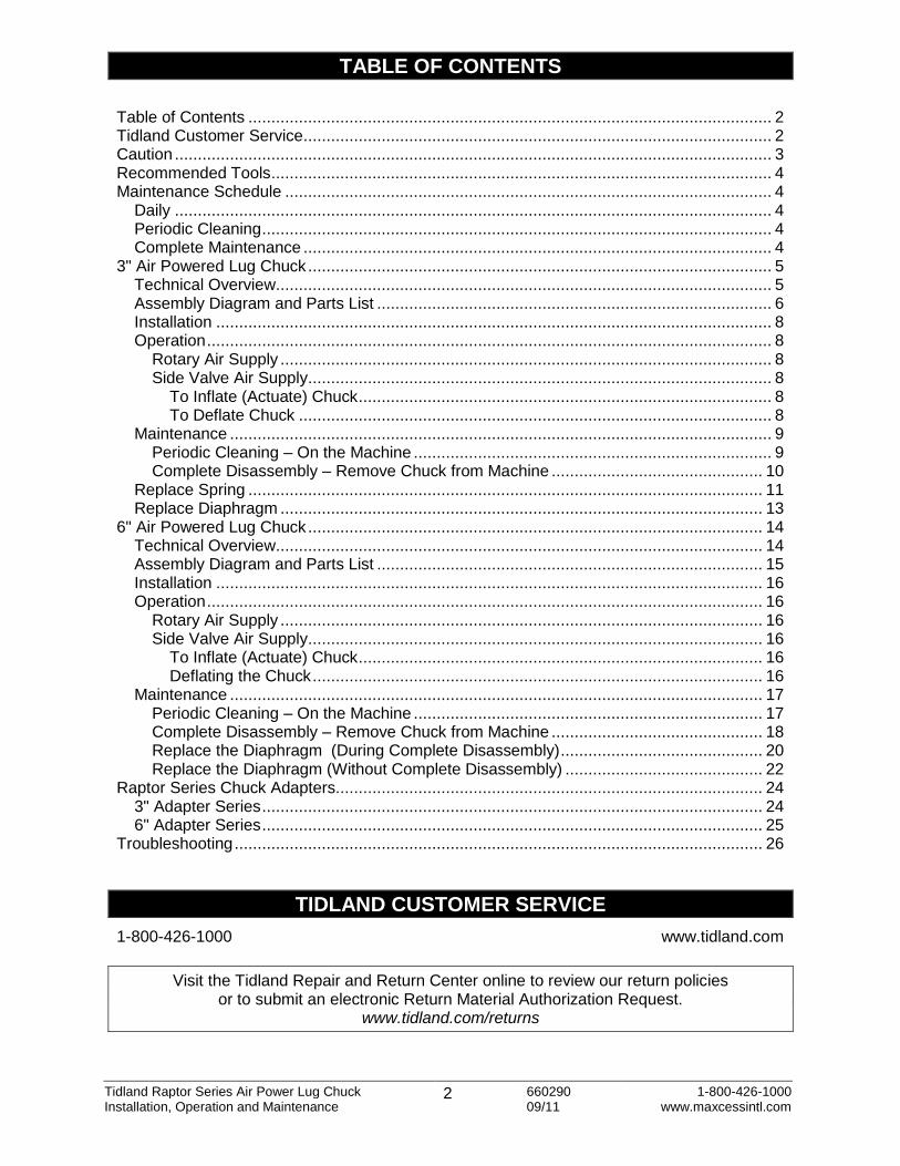
TABLE OF CONTENTS
Table of Contents .................................................................................................................. 2 Tidland Customer Service ...................................................................................................... 2 Caution .................................................................................................................................. 3 Recommended Tools ............................................................................................................. 4 Maintenance Schedule .......................................................................................................... 4
Daily .................................................................................................................................. 4 Periodic Cleaning ............................................................................................................... 4 Complete Maintenance ...................................................................................................... 4
3" Air Powered Lug Chuck ..................................................................................................... 5 Technical Overview............................................................................................................ 5 Assembly Diagram and Parts List ...................................................................................... 6 Installation ......................................................................................................................... 8 Operation ........................................................................................................................... 8
Rotary Air Supply ........................................................................................................... 8 Side Valve Air Supply..................................................................................................... 8
To Inflate (Actuate) Chuck .......................................................................................... 8 To Deflate Chuck ....................................................................................................... 8
Maintenance ...................................................................................................................... 9 Periodic Cleaning – On the Machine .............................................................................. 9 Complete Disassembly – Remove Chuck from Machine .............................................. 10
Replace Spring ................................................................................................................ 11 Replace Diaphragm ......................................................................................................... 13
6" Air Powered Lug Chuck ................................................................................................... 14 Technical Overview.......................................................................................................... 14 Assembly Diagram and Parts List .................................................................................... 15 Installation ....................................................................................................................... 16 Operation ......................................................................................................................... 16
Rotary Air Supply ......................................................................................................... 16 Side Valve Air Supply................................................................................................... 16
To Inflate (Actuate) Chuck ........................................................................................ 16 Deflating the Chuck .................................................................................................. 16
Maintenance .................................................................................................................... 17 Periodic Cleaning – On the Machine ............................................................................ 17 Complete Disassembly – Remove Chuck from Machine .............................................. 18 Replace the Diaphragm (During Complete Disassembly) ............................................ 20 Replace the Diaphragm (Without Complete Disassembly) ........................................... 22
Raptor Series Chuck Adapters............................................................................................. 24 3" Adapter Series ............................................................................................................. 24 6" Adapter Series ............................................................................................................. 25
Troubleshooting ................................................................................................................... 26
TIDLAND CUSTOMER SERVICE
1-800-426-1000 www.tidland.com
Visit the Tidland Repair and Return Center online to review our return policies or to submit an electronic Return Material Authorization Request.
www.tidland.com/returns
Tidland Raptor Series Air Power Lug Chuck 3 660290 1-800-426-1000 Installation, Operation and Maintenance 09/11 www.maxcessintl.com
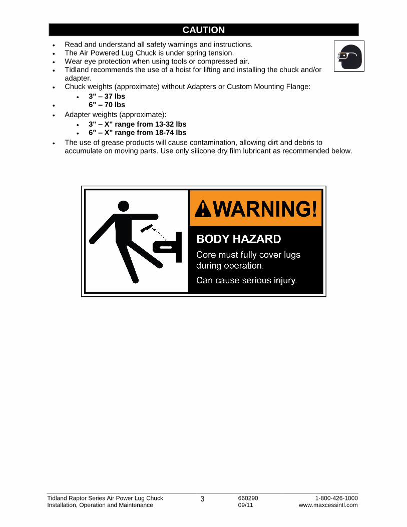
CAUTION
Read and understand all safety warnings and instructions. The Air Powered Lug Chuck is under spring tension. Wear eye protection when using tools or compressed air. Tidland recommends the use of a hoist for lifting and installing the chuck and/or
adapter. Chuck weights (approximate) without Adapters or Custom Mounting Flange:
3" – 37 lbs 6" – 70 lbs
Adapter weights (approximate):
3" – X" range from 13-32 lbs 6" – X" range from 18-74 lbs
The use of grease products will cause contamination, allowing dirt and debris to accumulate on moving parts. Use only silicone dry film lubricant as recommended below.

Tidland Raptor Series Air Power Lug Chuck 4 660290 1-800-426-1000 Installation, Operation and Maintenance 09/11 www.maxcessintl.com
RECOMMENDED TOOLS
Clean, non-lubricated air supply: 80-120 psi (5.5-8.3 bar) for proper operation. Hex wrenches: 1/8", 3/16", 3/8" Tidland Inflation Tool for Side Valve use Tidland Inflation Tool:
Quick Release w/ gauge (Part No. 128052) Quick Release w/o gauge (Part No. 128054) Schrader w/ gauge (Part No. 128053) Schrader w/o gauge (Part No. 128055)
Tidland Air Release Tool (Part No. 111630) Dow Corning Molykote® 557 Dry Film Lubricant (Do not use any grease.) LOCTITE® 242 (blue) Jacking screws (#10-32NF x 1 1/4" socket head cap screw recommended)
For more accessories to help with your winding processes, visit www.tidland.com.
MAINTENANCE SCHEDULE
For optimal performance, keep chucks free of buildup and corrosion by performing regular maintenance.
Daily Throughout the operating shift, use compressed air to keep chuck free of any visible dust and debris.
Periodic Cleaning If application of compressed air does not remove dust or debris buildup, or if lugs are sticking, Tidland recommends partial disassembly of the chuck for cleaning and lubrication, which can be done without removing the chuck from the machine. Remove lugs; clean lugs and lug slots. Lubricate wear surfaces with dry film lubricant spray before reassembly.
Complete Maintenance Every 6 months, remove the chuck from the machine for complete disassembly. Clean all parts thoroughly, removing debris and corrosion and inspect for wear. Lubricate wear surfaces with dry film lubricant spray before reassembly. In severe applications, more frequent maintenance may be necessary

Tidland Raptor Series Air Power Lug Chuck 5 660290 1-800-426-1000 Installation, Operation and Maintenance 09/11 www.maxcessintl.com
3" AIR POWERED LUG CHUCK
Technical Overview The 3" Air Powered Lug Chuck uses pneumatic actuation of a rolling diaphragm, piston and wedge block to expand three cast steel lugs. The serrated, wide-footprint lugs distribute internal core pressure that results in 500-600 ft·lbs (6000-7200 in·lbs) of potential torque, depending upon core material. A mechanical spring, close tolerances and minimal gaps between moving parts ensure positive, reliable lug retraction.
The 3" Air Powered Lug Chuck is designed to fit 3" cores (+.010"/+.020").
The 3" Air Powered Lug Chuck mounts using a 7" bolt circle. If your spindle has a different bolt pattern, a Custom Mounting Flange is required. Your chuck will be shipped with the flange already mounted.
Contact a Tidland Customer Service Representative for additional information about custom options. (1-800-426-1000).
CYLINDER HOUSING
CHUCK BODY
LUGS
7.062"
4.059"
Ø 7.00" BOLT CIRCLE
CUSTOM MOUNTING FLANGE

Tidland Raptor Series Air Power Lug Chuck 6 660290 1-800-426-1000 Installation, Operation and Maintenance 09/11 www.maxcessintl.com
3" AIR POWERED LUG CHUCK
Assembly Diagram and Parts List Part No. 592211
692374 (after Nov 2008)
ITEM DESCRIPTION QTY PART NO.
592211
PART NO.
692374
ENKEL NO.
697300
1 3" AP CHUCK BODY 1 570587 692373 692373
2 LUG 3 586177 586177 586177
3 WIPER SEAL 1 662252 692367 692367
*4 GUIDE PIN 3 550568 690391 690391
5 SOC HD CPSCR 3/8-16NC X 1.5" LG (GRADE 8) 2 599047 599047 599047
6 CYLINDER HOUSING 1 572029 572029 634814
*7 SPRING 1 597404 692369 692369
A Custom Mounting Flange is available for side valve inflation.
* Items 4 and 7 may vary in appearance depending upon your chuck part number. Assembly instructions are the same.
ACTUATOR ASSEMBLY
(ITEMS 8-16) NEXT PAGE
7
6
5
4
2
3
1
Tidland Raptor Series Air Power Lug Chuck 7 660290 1-800-426-1000 Installation, Operation and Maintenance 09/11 www.maxcessintl.com
3" AIR POWERED LUG CHUCK
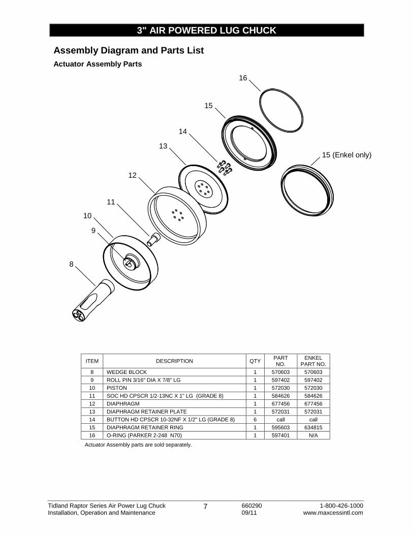
Assembly Diagram and Parts List
Actuator Assembly Parts
ITEM DESCRIPTION QTY PART NO.
ENKEL PART NO.
8 WEDGE BLOCK 1 570603 570603
9 ROLL PIN 3/16" DIA X 7/8" LG 1 597402 597402
10 PISTON 1 572030 572030
11 SOC HD CPSCR 1/2-13NC X 1" LG (GRADE 8) 1 584626 584626
12 DIAPHRAGM 1 677456 677456
13 DIAPHRAGM RETAINER PLATE 1 572031 572031
14 BUTTON HD CPSCR 10-32NF X 1/2" LG (GRADE 8) 6 call call
15 DIAPHRAGM RETAINER RING 1 595603 634815
16 O-RING (PARKER 2-248 N70) 1 597401 N/A
Actuator Assembly parts are sold separately.
14
8
9
11
13
12
15
16
10
15 (Enkel only)
Tidland Raptor Series Air Power Lug Chuck 8 660290 1-800-426-1000 Installation, Operation and Maintenance 09/11 www.maxcessintl.com
3" AIR POWERED LUG CHUCK
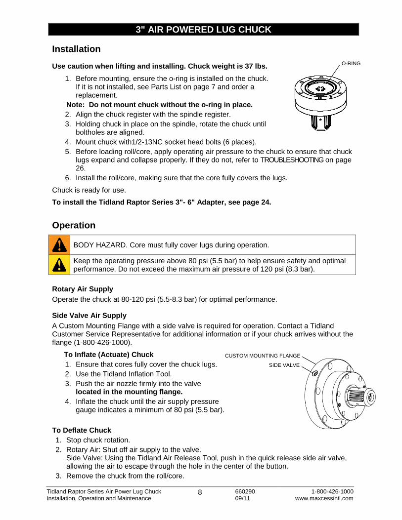
Installation
Use caution when lifting and installing. Chuck weight is 37 lbs.
1. Before mounting, ensure the o-ring is installed on the chuck. If it is not installed, see Parts List on page 7 and order a replacement.
Note: Do not mount chuck without the o-ring in place.
2. Align the chuck register with the spindle register.
3. Holding chuck in place on the spindle, rotate the chuck until boltholes are aligned.
4. Mount chuck with1/2-13NC socket head bolts (6 places).
5. Before loading roll/core, apply operating air pressure to the chuck to ensure that chuck lugs expand and collapse properly. If they do not, refer to TROUBLESHOOTING on page 26.
6. Install the roll/core, making sure that the core fully covers the lugs.
Chuck is ready for use.
To install the Tidland Raptor Series 3"- 6" Adapter, see page 24.
Operation
Rotary Air Supply
Operate the chuck at 80-120 psi (5.5-8.3 bar) for optimal performance.
Side Valve Air Supply
A Custom Mounting Flange with a side valve is required for operation. Contact a Tidland Customer Service Representative for additional information or if your chuck arrives without the flange (1-800-426-1000).
To Inflate (Actuate) Chuck
1. Ensure that cores fully cover the chuck lugs.
2. Use the Tidland Inflation Tool.
3. Push the air nozzle firmly into the valve located in the mounting flange.
4. Inflate the chuck until the air supply pressure gauge indicates a minimum of 80 psi (5.5 bar).
To Deflate Chuck
1. Stop chuck rotation.
2. Rotary Air: Shut off air supply to the valve. Side Valve: Using the Tidland Air Release Tool, push in the quick release side air valve, allowing the air to escape through the hole in the center of the button.
3. Remove the chuck from the roll/core.
BODY HAZARD. Core must fully cover lugs during operation.
Keep the operating pressure above 80 psi (5.5 bar) to help ensure safety and optimal performance. Do not exceed the maximum air pressure of 120 psi (8.3 bar).
O-RING
SIDE VALVE
CUSTOM MOUNTING FLANGE

Tidland Raptor Series Air Power Lug Chuck 9 660290 1-800-426-1000 Installation, Operation and Maintenance 09/11 www.maxcessintl.com
3" AIR POWERED LUG CHUCK
Maintenance If compressed air does not remove dust or debris buildup, or if lugs are sticking, Tidland recommends removing the lugs for cleaning and lubrication. This can be done without removing the chuck from the machine.
Periodic Cleaning – On the Machine
1. Remove adapter from chuck (page 25), if installed.
2. STOP: Do not remove all three chuck lugs at the same time. At least one lug must stay in place to keep the wedge block slots aligned with the chuck body lug slots.
3. Using 3/16" hex wrench, remove one or two guide pins and lug(s). Inspect for wear and replace if necessary.
4. Clean out lug slots, wipe debris from all parts, and remove any corrosion. Note: If debris or corrosion cannot be removed, Tidland recommends removing the chuck from the machine for complete disassembly and maintenance. See page 10.
5. Lubricate bottom of lugs and lug slots with silicone dry film lubricant. Reinstall lugs in slots.
6. Apply LOCTITE 242 to guide pin threads only and finger-tighten until threads are fully engaged. Note: Keep guide pin surface free of LOCTITE.
7. Repeat Steps 4 through 6 for the remaining lug(s).
GUIDE PINS (3 PLCS)
LUGS (3 PLCS)

Tidland Raptor Series Air Power Lug Chuck 10 660290 1-800-426-1000 Installation, Operation and Maintenance 09/11 www.maxcessintl.com
3" AIR POWERED LUG CHUCK
Complete Disassembly – Remove Chuck from Machine
Tidland recommends complete disassembly for cleaning and lubrication every 6 months; in severe applications, more frequent maintenance may be necessary. The chuck must be removed from the machine for complete disassembly.
1. Remove adapter from chuck (page 25), if installed. Deflate chuck completely.
2. Remove chuck from machine and set on workbench, backplate facing up (Fig. 1).
3. Use #10-32NF screws in the jacking threads to lift the diaphragm retainer ring. AVOID over-extending the diaphragm when pulling up the diaphragm ring (Fig. 1).
4. Inspect the diaphragm for wear at the folds and replace if necessary (page 13).
5. Push the diaphragm back down into place around the actuator assembly (Fig. 2, 3).
6. Turn the chuck over onto the backplate. Caution! Ensure that the diaphragm edges are not pinched between the chuck body and the work surface.
7. Using a 3/16" hex wrench, remove two guide pins and two lugs (Fig. 4).
Caution! If all three guide pins are removed at once, lugs could pop out and result in
sudden release of spring tension.
8. Remove the third guide pin, using caution (Fig. 5). The remaining lug holds spring tension; if it is not easily removed, hold it firmly in place and turn the chuck over again so the backplate is facing up.
Caution! If the lug is jarred loose or falls out, tension is released and the actuator assembly
may expand outward.
9. Compress the actuator assembly by hand to release spring tension and remove the remaining lug (Fig. 6).
ACTUATOR COMPRESSED
LUG REMOVED
GUIDE PINS (1, 2)
REMAINING LUG
GUIDE PIN (3) (3)
Fig. 4 Fig. 5 Fig. 6
Fig. 3 Fig. 2
JACKING SCREWS
Fig. 1
Tidland Raptor Series Air Power Lug Chuck 11 660290 1-800-426-1000 Installation, Operation and Maintenance 09/11 www.maxcessintl.com
3" AIR POWERED LUG CHUCK
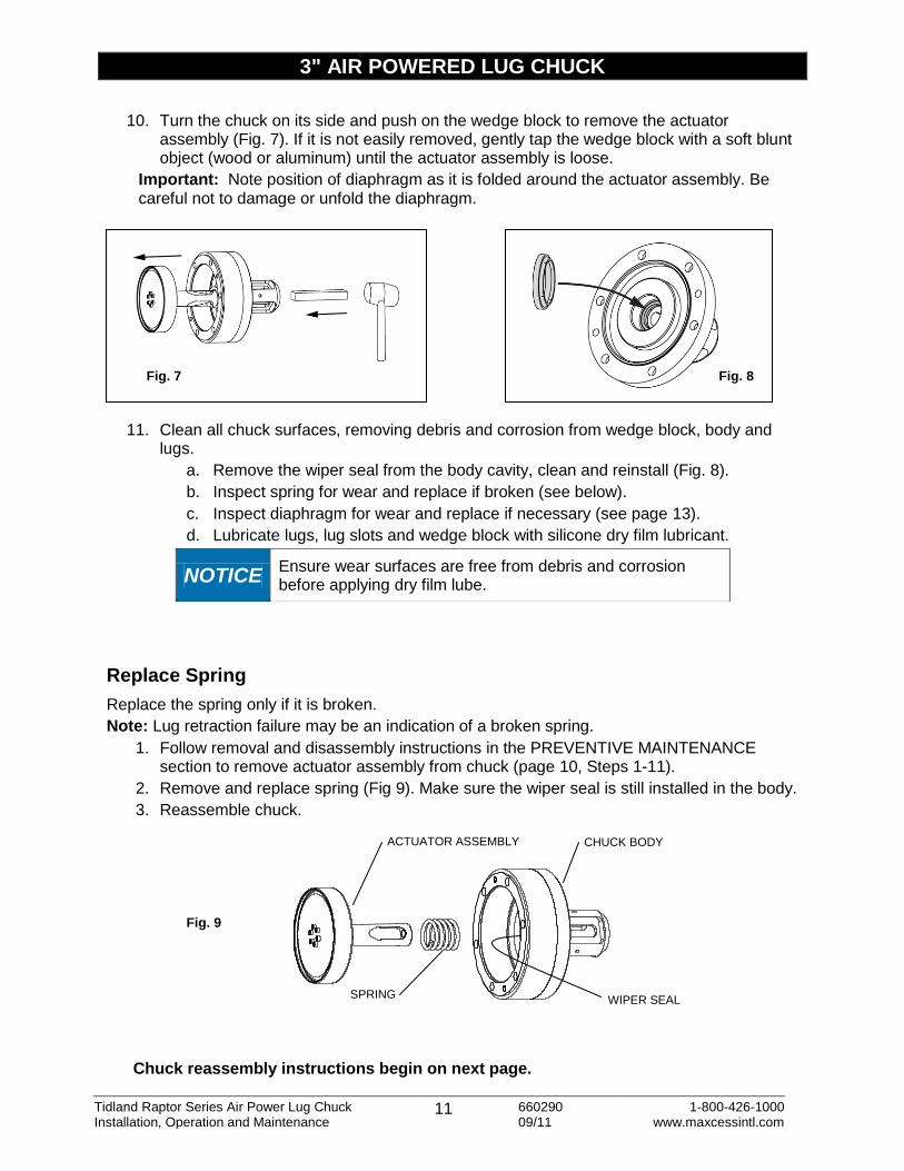
10. Turn the chuck on its side and push on the wedge block to remove the actuator assembly (Fig. 7). If it is not easily removed, gently tap the wedge block with a soft blunt object (wood or aluminum) until the actuator assembly is loose.
Important: Note position of diaphragm as it is folded around the actuator assembly. Be careful not to damage or unfold the diaphragm.
11. Clean all chuck surfaces, removing debris and corrosion from wedge block, body and lugs.
a. Remove the wiper seal from the body cavity, clean and reinstall (Fig. 8).
b. Inspect spring for wear and replace if broken (see below).
c. Inspect diaphragm for wear and replace if necessary (see page 13).
d. Lubricate lugs, lug slots and wedge block with silicone dry film lubricant.
Replace Spring
Replace the spring only if it is broken.
Note: Lug retraction failure may be an indication of a broken spring.
1. Follow removal and disassembly instructions in the PREVENTIVE MAINTENANCE section to remove actuator assembly from chuck (page 10, Steps 1-11).
2. Remove and replace spring (Fig 9). Make sure the wiper seal is still installed in the body.
3. Reassemble chuck.
Chuck reassembly instructions begin on next page.
NOTICE Ensure wear surfaces are free from debris and corrosion before applying dry film lube.
Fig. 7 Fig. 8
SPRING
ACTUATOR ASSEMBLY CHUCK BODY
Fig. 9
WIPER SEAL

Tidland Raptor Series Air Power Lug Chuck 12 660290 1-800-426-1000 Installation, Operation and Maintenance 09/11 www.maxcessintl.com
3" AIR POWERED LUG CHUCK
Reassemble Chuck
1. Reinstall actuator assembly in the chuck body. Make sure that the wiper seal is in place in the body. Note: To reinstall the lugs, slots in wedge block must align with lug slots in chuck body.
2. Compress the actuator assembly in the chuck body far enough to install one lug.
3. Apply a small amount of LOCTITE 242 to the threads of the guide pin and install. Fully engage threads. Do not overtighten.
4. Place the back surface of the chuck on the workbench and reinstall the remaining lugs.
5. Turn the chuck over. Carefully push the diaphragm down around the actuator assembly.
6. Press the bead on the diaphragm into the groove in the retainer ring. Ensure that the bead in pressed in all the way around.
7. Push the retainer ring into place in the chuck body. Note: If diaphragm edges are properly aligned in the retainer ring groove, the ring seats almost completely in the chuck backplate. Complete compression occurs when the chuck is reinstalled on the machine.
Complete instructions for replacing the diaphragm are on page 13.
O- RING
LUG SLOT (1) OF (3)
WEDGE BLOCK SLOT (1) OF (3)
WIPER SEAL
Tidland Raptor Series Air Power Lug Chuck 13 660290 1-800-426-1000 Installation, Operation and Maintenance 09/11 www.maxcessintl.com
3" AIR POWERED LUG CHUCK
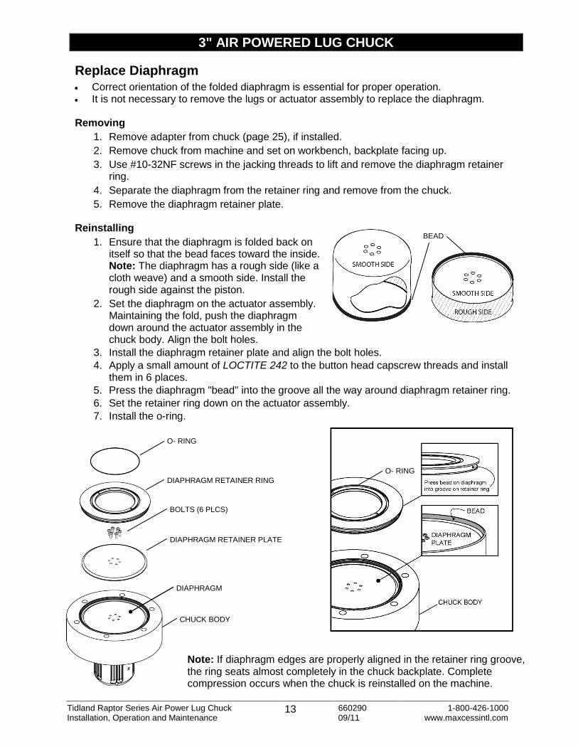
Replace Diaphragm Correct orientation of the folded diaphragm is essential for proper operation. It is not necessary to remove the lugs or actuator assembly to replace the diaphragm. Removing
1. Remove adapter from chuck (page 25), if installed.
2. Remove chuck from machine and set on workbench, backplate facing up.
3. Use #10-32NF screws in the jacking threads to lift and remove the diaphragm retainer ring.
4. Separate the diaphragm from the retainer ring and remove from the chuck.
5. Remove the diaphragm retainer plate. Reinstalling
1. Ensure that the diaphragm is folded back on itself so that the bead faces toward the inside. Note: The diaphragm has a rough side (like a cloth weave) and a smooth side. Install the rough side against the piston.
2. Set the diaphragm on the actuator assembly. Maintaining the fold, push the diaphragm down around the actuator assembly in the chuck body. Align the bolt holes.
3. Install the diaphragm retainer plate and align the bolt holes.
4. Apply a small amount of LOCTITE 242 to the button head capscrew threads and install them in 6 places.
5. Press the diaphragm "bead" into the groove all the way around diaphragm retainer ring.
6. Set the retainer ring down on the actuator assembly.
7. Install the o-ring.
O- RING
Note: If diaphragm edges are properly aligned in the retainer ring groove, the ring seats almost completely in the chuck backplate. Complete compression occurs when the chuck is reinstalled on the machine.
BEAD
DIAPHRAGM RETAINER RING
BOLTS (6 PLCS)
DIAPHRAGM RETAINER PLATE
DIAPHRAGM
O- RING
CHUCK BODY
Tidland Raptor Series Air Power Lug Chuck 14 660290 1-800-426-1000 Installation, Operation and Maintenance 09/11 www.maxcessintl.com
6" AIR POWERED LUG CHUCK
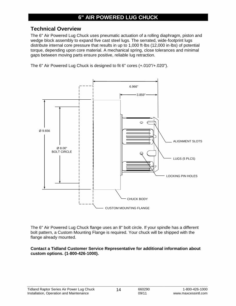
Technical Overview The 6" Air Powered Lug Chuck uses pneumatic actuation of a rolling diaphragm, piston and wedge block assembly to expand five cast steel lugs. The serrated, wide-footprint lugs distribute internal core pressure that results in up to 1,000 ft·lbs (12,000 in·lbs) of potential torque, depending upon core material. A mechanical spring, close tolerances and minimal gaps between moving parts ensure positive, reliable lug retraction.
The 6" Air Powered Lug Chuck is designed to fit 6" cores (+.010"/+.020").
The 6" Air Powered Lug Chuck flange uses an 8" bolt circle. If your spindle has a different bolt pattern, a Custom Mounting Flange is required. Your chuck will be shipped with the flange already mounted.
Contact a Tidland Customer Service Representative for additional information about custom options. (1-800-426-1000).
CHUCK BODY
LUGS (5 PLCS)
CUSTOM MOUNTING FLANGE
LOCKING PIN HOLES
ALIGNMENT SLOTS
6.966"
3.859"
Ø 8.00" BOLT CIRCLE
Ø 9.656
Tidland Raptor Series Air Power Lug Chuck 15 660290 1-800-426-1000 Installation, Operation and Maintenance 09/11 www.maxcessintl.com
11*
14* 13*
12*
10*
9*
8*
7*
6*
5* 1 2
4
15*
3
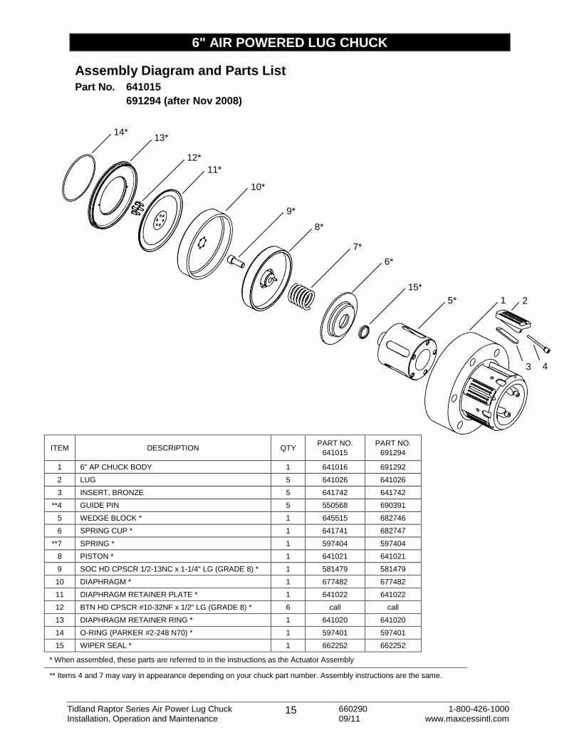
6" AIR POWERED LUG CHUCK
Assembly Diagram and Parts List Part No. 641015
691294 (after Nov 2008)
ITEM DESCRIPTION QTY PART NO.
641015
PART NO.
691294
1 6" AP CHUCK BODY 1 641016 691292
2 LUG 5 641026 641026
3 INSERT, BRONZE 5 641742 641742
**4 GUIDE PIN 5 550568 690391
5 WEDGE BLOCK * 1 645515 682746
6 SPRING CUP * 1 641741 682747
**7 SPRING * 1 597404 597404
8 PISTON * 1 641021 641021
9 SOC HD CPSCR 1/2-13NC x 1-1/4" LG (GRADE 8) * 1 581479 581479
10 DIAPHRAGM * 1 677482 677482
11 DIAPHRAGM RETAINER PLATE * 1 641022 641022
12 BTN HD CPSCR #10-32NF x 1/2" LG (GRADE 8) * 6 call call
13 DIAPHRAGM RETAINER RING * 1 641020 641020
14 O-RING (PARKER #2-248 N70) * 1 597401 597401
15 WIPER SEAL * 1 662252 662252
* When assembled, these parts are referred to in the instructions as the Actuator Assembly
** Items 4 and 7 may vary in appearance depending on your chuck part number. Assembly instructions are the same.

Tidland Raptor Series Air Power Lug Chuck 16 660290 1-800-426-1000 Installation, Operation and Maintenance 09/11 www.maxcessintl.com
6" AIR POWERED LUG CHUCK
Installation
1. Before mounting, ensure the o-ring is installed on the chuck. If it is not installed, see PARTS LIST on page 15 and order a replacement.
Caution! Do not mount chuck without the o-ring in place.
2. Align the chuck register with the spindle register. 3. Holding chuck in place on the spindle, rotate the chuck until bolt
holes are aligned. 4. Insert 1/2-13NC socket head bolts (6 places). 5. Before loading roll/core, apply operating air pressure to the chuck
to ensure that chuck lugs expand and collapse properly. If they do not, refer to TROUBLESHOOTING on page 26.
6. Install roll/core, making sure that the core fully covers the lugs.
Chuck is ready for use.
To install the Raptor Series Adapter, see pages 24-25.
Operation
Rotary Air Supply
Operate the chuck at 80-120 psi (5.5-8.3 bar) for optimal performance.
Side Valve Air Supply
A Custom Mounting Flange with a side valve is required for operation. Contact a Tidland Customer Service Representative for additional information or if your chuck arrives without the flange (1-800-426-1000).
To Inflate (Actuate) Chuck
1. Ensure that cores fully cover the chuck lugs.
2. Use the Tidland Inflation Tool.
3. Push the air nozzle firmly into the valve located in the mounting flange.
4. Inflate the chuck until the air supply pressure gauge indicates a minimum of 80 psi (5.5 bar).
Deflating the Chuck
1. Stop chuck rotation.
2. Rotary Air: Shut off air supply to the valve. Side Valve: Using the Tidland Air Release Tool, push in the quick release side air valve, allowing the air to escape through the hole in the center of the button.
3. Remove the chuck from the roll/core.
WARNING Use a hoist and safe handling procedures during installation. Chuck weight is 70 lbs. It is equipped with a 3/8-16 threaded hole to
accommodate a screw eye for lifting.
BODY HAZARD. Core must fully cover lugs during operation.
Keep the operating pressure above 80 psi (5.5 bar) to help ensure safety and optimal performance. Do not exceed the maximum air pressure of 120 psi (8.3 bar).
O-RING
SIDE VALVE
CUSTOM MOUNTING FLANGE
3” CHUCK SHOWN

Tidland Raptor Series Air Power Lug Chuck 17 660290 1-800-426-1000 Installation, Operation and Maintenance 09/11 www.maxcessintl.com
GUIDE PINS (5 PLCS)
LUGS (5 PLCS)
6" AIR POWERED LUG CHUCK
Maintenance If compressed air does not remove dust or debris buildup, or if lugs are sticking, Tidland recommends removing the lugs for cleaning and lubrication. This can be done without removing the chuck from the machine.
Periodic Cleaning – On the Machine
Periodic cleaning of the lugs and slots is essential for proper operation. The following steps are done without removing chuck from the machine.
1. Remove adapter from chuck (page 25), if installed.
2. STOP: Do not remove all five chuck lugs at the same time. At least one lug must stay in place to keep the wedge block slots aligned with the chuck body lug slots.
3. Using 3/16" hex drive wrench, remove the guide pins from the topmost lugs (Fig. 1)
4. Rotate the chuck to remove the bronze inserts. Note: The inserts may not come out. It is not normally necessary to remove them. Do not pry them out.
5. Clean out lug slots. Inspect lugs and inserts for wear and replace if necessary.
6. Clean chuck lugs and bronze inserts (if removed). Lubricate bottom of inserts, lugs and lug slots with spray.
7. Reinstall bronze inserts, if removed, and lugs to the topmost slots on the chuck. Note: Pay close attention to the orientation of the insert. Taper should point toward chuck flange (Fig. 2).
8. Apply LOCTITE 242 (no primer) to guide pin threads only. Keep guide pin surface free of LOCTITE.
9. With one hand on a lug, tighten the guide pin just until you feel the lug move, then back the guide pin out 1/8 turn. Repeat for the other lugs.
10. Rotate the chuck to move the remaining two lugs to the topmost position and repeat the procedure (Steps 4-10).
11. Slip a section of core over the chuck to test the fit. If it is tight, determine which lugs are expanded and back off the guide pins until lugs collapse enough to fit the core.
NOTICE Ensure wear surfaces are free from debris and corrosion before applying dry film lube.
Fig. 1
TAPER Fig. 2
Tidland Raptor Series Air Power Lug Chuck 18 660290 1-800-426-1000 Installation, Operation and Maintenance 09/11 www.maxcessintl.com
6" AIR POWERED LUG CHUCK
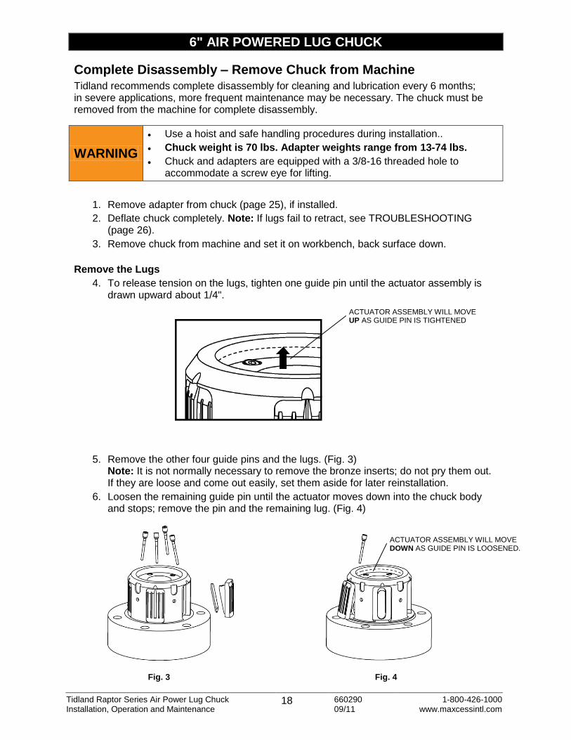
Complete Disassembly – Remove Chuck from Machine Tidland recommends complete disassembly for cleaning and lubrication every 6 months; in severe applications, more frequent maintenance may be necessary. The chuck must be removed from the machine for complete disassembly.
1. Remove adapter from chuck (page 25), if installed.
2. Deflate chuck completely. Note: If lugs fail to retract, see TROUBLESHOOTING (page 26).
3. Remove chuck from machine and set it on workbench, back surface down.
Remove the Lugs
4. To release tension on the lugs, tighten one guide pin until the actuator assembly is drawn upward about 1/4".
5. Remove the other four guide pins and the lugs. (Fig. 3) Note: It is not normally necessary to remove the bronze inserts; do not pry them out. If they are loose and come out easily, set them aside for later reinstallation.
6. Loosen the remaining guide pin until the actuator moves down into the chuck body and stops; remove the pin and the remaining lug. (Fig. 4)
WARNING
Use a hoist and safe handling procedures during installation..
Chuck weight is 70 lbs. Adapter weights range from 13-74 lbs. Chuck and adapters are equipped with a 3/8-16 threaded hole to
accommodate a screw eye for lifting.
ACTUATOR ASSEMBLY WILL MOVE UP AS GUIDE PIN IS TIGHTENED
Fig. 3 Fig. 4
ACTUATOR ASSEMBLY WILL MOVE DOWN AS GUIDE PIN IS LOOSENED.

Tidland Raptor Series Air Power Lug Chuck 19 660290 1-800-426-1000 Installation, Operation and Maintenance 09/11 www.maxcessintl.com
6" AIR POWERED LUG CHUCK
Remove the Actuator Assembly
7. Turn the chuck on its side.
8. Push the actuator assembly out. If it is not easily removed, gently tap the wedge block with a soft blunt object (wood or aluminum) until the assembly is loose.
Note: It is not normally necessary to remove the bronze inserts; do not pry them out. If they are loose and come out easily, set them aside and reinstall during reassembly.
9. With the diaphragm retainer ring facing up, set the actuator assembly on the workbench.
Disassemble the Actuator Assembly
1. Remove chuck from machine and remove actuator assembly from chuck.
2. Remove the o-ring from the diaphragm retainer ring. Inspect for cracks and replace if necessary.
3. Remove the button head capscrews from the diaphragm retainer plate.
4. Lift the retainer plate and ring off of the diaphragm.
5. Important: Note position of diaphragm as folded around the piston. Remove the diaphragm from the piston. Inspect the diaphragm for cracks, tears or worn areas. Replace diaphragm if broken threads are visible.
6. Clean all actuator assembly parts, including the slots in the wedge block. Note: It is not necessary to remove the bronze inserts; do not pry them out. If they are loose and come out easily, set them aside and reinstall during reassembly. (continued next page)
O-RING
BUTTON HEAD CAPSCREWS
DIAPHRAGM RETAINER PLATE
DIAPHRAGM
PISTON
WEDGE BLOCK ASSEMBLY
BRONZE INSERTS
DIAPHRAGM RETAINER RING
WOOD BLOCK
ACTUATOR ASSEMBLY
CHUCK BODY
DIAPHRAGM RETAINER RING

Tidland Raptor Series Air Power Lug Chuck 20 660290 1-800-426-1000 Installation, Operation and Maintenance 09/11 www.maxcessintl.com
6" AIR POWERED LUG CHUCK
Disassemble the Actuator Assembly (continued)
7. Remove the bolt (use 3/8" hex drive) that holds the piston to the wedge block assembly.
8. Lift the piston off the wedge block.
9. Remove and inspect the spring. Replace spring if broken or excessively corroded.
10. Lift spring cup (with wiper seal) off the wedge block assembly and clean out underneath.
11. Reassemble after cleaning and inspection; reinstall the diaphragm (page 22).
Note: During reassembly, pay close attention to the orientation of the spring cup as shown in the illustration. Ensure that the roll pin is installed in the piston: align it with the hole in the wedge block rod.
Replace the Diaphragm (During Complete Disassembly)
1. Note: The diaphragm has a rough side (like a cloth weave) and a smooth side. Install the rough side against the piston.
2. Set the diaphragm over the piston and align the bolt holes. Fold the edges of the diaphragm up so that the "bead" faces to the inside.
3. Install the diaphragm retainer plate and align the bolt holes.
4. Apply a small amount of LOCTITE 242 to the bolt threads and install them in 6 places.
5. Press the diaphragm "bead" into the groove all the way around the diaphragm retainer ring.
6. Set the retainer ring down on the actuator assembly.
7. Actuator assembly is ready to be inserted into the chuck body.
BEAD
DIAPHRAGM FOLD
RETAINER RING
WIPER SEAL
ROLL PIN
PISTON
WEDGE BLOCK ROD
SPRING
BOLT
SPRING CUP
WEDGE BLOCK
Tidland Raptor Series Air Power Lug Chuck 21 660290 1-800-426-1000 Installation, Operation and Maintenance 09/11 www.maxcessintl.com
6" AIR POWERED LUG CHUCK
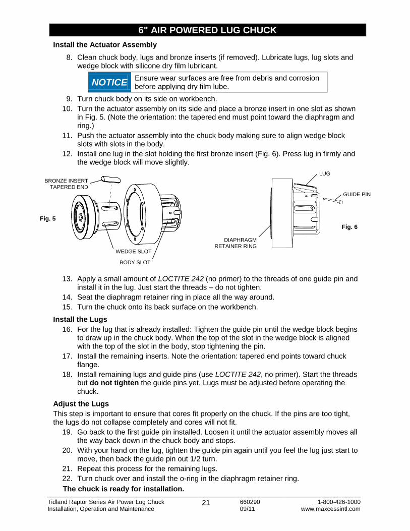
Install the Actuator Assembly
8. Clean chuck body, lugs and bronze inserts (if removed). Lubricate lugs, lug slots and wedge block with silicone dry film lubricant.
NOTICE Ensure wear surfaces are free from debris and corrosion before applying dry film lube.
9. Turn chuck body on its side on workbench.
10. Turn the actuator assembly on its side and place a bronze insert in one slot as shown in Fig. 5. (Note the orientation: the tapered end must point toward the diaphragm and ring.)
11. Push the actuator assembly into the chuck body making sure to align wedge block slots with slots in the body.
12. Install one lug in the slot holding the first bronze insert (Fig. 6). Press lug in firmly and the wedge block will move slightly.
13. Apply a small amount of LOCTITE 242 (no primer) to the threads of one guide pin and
install it in the lug. Just start the threads – do not tighten.
14. Seat the diaphragm retainer ring in place all the way around.
15. Turn the chuck onto its back surface on the workbench.
Install the Lugs
16. For the lug that is already installed: Tighten the guide pin until the wedge block begins to draw up in the chuck body. When the top of the slot in the wedge block is aligned with the top of the slot in the body, stop tightening the pin.
17. Install the remaining inserts. Note the orientation: tapered end points toward chuck flange.
18. Install remaining lugs and guide pins (use LOCTITE 242, no primer). Start the threads but do not tighten the guide pins yet. Lugs must be adjusted before operating the chuck.
Adjust the Lugs
This step is important to ensure that cores fit properly on the chuck. If the pins are too tight, the lugs do not collapse completely and cores will not fit.
19. Go back to the first guide pin installed. Loosen it until the actuator assembly moves all the way back down in the chuck body and stops.
20. With your hand on the lug, tighten the guide pin again until you feel the lug just start to move, then back the guide pin out 1/2 turn.
21. Repeat this process for the remaining lugs.
22. Turn chuck over and install the o-ring in the diaphragm retainer ring.
The chuck is ready for installation.
Fig. 5
BRONZE INSERT TAPERED END
WEDGE SLOT
BODY SLOT
GUIDE PIN
LUG
DIAPHRAGM RETAINER RING
Fig. 6

Tidland Raptor Series Air Power Lug Chuck 22 660290 1-800-426-1000 Installation, Operation and Maintenance 09/11 www.maxcessintl.com
6" AIR POWERED LUG CHUCK
Replace the Diaphragm (Without Complete Disassembly)
Removal
1. Remove adapter from chuck (page 25), if installed, and remove the chuck from the machine.
2. Place the chuck on workbench with diaphragm retainer ring facing up.
3. Use #10-32NF screws in the jacking threads to loosen the diaphragm ring and pull it away from the chuck assembly.
4. Lift up on the diaphragm retainer ring.
5. Separate the retainer ring from the diaphragm.
6. Remove the button head capscrews from diaphragm retainer plate and remove plate.
7. Remove the diaphragm from the chuck body.
Replacement
1. Ensure that the diaphragm is folded back on itself so that the bead faces toward the inside. Note: The diaphragm has a rough side (like a cloth weave) and a smooth side. Install the rough side against the piston.
2. Set the diaphragm over the piston. Maintaining the fold, push the diaphragm down around the actuator assembly in the chuck body. Align the bolt holes.
3. Install the diaphragm retainer plate and align the bolt holes.
4. Apply a small amount of LOCTITE 242 to the button head capscrew threads and install them in 6 places.
5. Press the diaphragm "bead" into the groove all the way around diaphragm retainer ring.
6. Set the retainer ring down on the actuator assembly.
7. Install the o-ring.
BEAD
DIAPHRAGM
JACKING SCREWS
DIAPHRAGM RETAINER RING
DIAPHRAGM RETAINER RING
BOLTS (6 PLCS)
DIAPHRAGM RETAINER PLATE
DIAPHRAGM
O- RING
CHUCK BODY

Tidland Raptor Series Air Power Lug Chuck 23 660290 1-800-426-1000 Installation, Operation and Maintenance 09/11 www.maxcessintl.com
Intentional Blank Page
Tidland Raptor Series Air Power Lug Chuck 24 660290 1-800-426-1000 Installation, Operation and Maintenance 09/11 www.maxcessintl.com
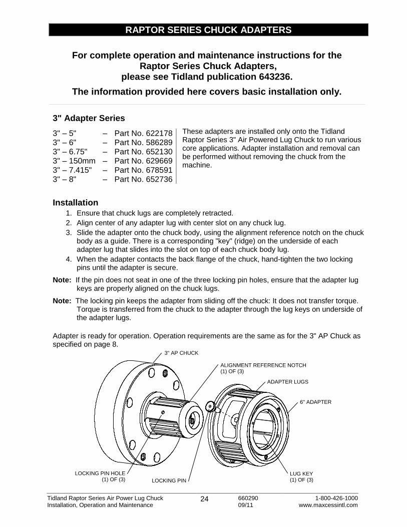
LOCKING PIN HOLE (1) OF (3)
ADAPTER LUGS
3" AP CHUCK
6" ADAPTER
LOCKING PIN
LUG KEY (1) OF (3)
ALIGNMENT REFERENCE NOTCH (1) OF (3)
RAPTOR SERIES CHUCK ADAPTERS
3" Adapter Series
These adapters are installed only onto the Tidland Raptor Series 3" Air Powered Lug Chuck to run various core applications. Adapter installation and removal can be performed without removing the chuck from the machine.
Installation
1. Ensure that chuck lugs are completely retracted.
2. Align center of any adapter lug with center slot on any chuck lug.
3. Slide the adapter onto the chuck body, using the alignment reference notch on the chuck body as a guide. There is a corresponding "key" (ridge) on the underside of each adapter lug that slides into the slot on top of each chuck body lug.
4. When the adapter contacts the back flange of the chuck, hand-tighten the two locking pins until the adapter is secure.
Note: If the pin does not seat in one of the three locking pin holes, ensure that the adapter lug keys are properly aligned on the chuck lugs.
Note: The locking pin keeps the adapter from sliding off the chuck: It does not transfer torque. Torque is transferred from the chuck to the adapter through the lug keys on underside of the adapter lugs.
Adapter is ready for operation. Operation requirements are the same as for the 3" AP Chuck as specified on page 8.
3" – 5" – Part No. 622178 3" – 6" – Part No. 586289 3" – 6.75" – Part No. 652130 3" – 150mm – Part No. 629669 3" – 7.415" – Part No. 678591 3" – 8" – Part No. 652736
For complete operation and maintenance instructions for the Raptor Series Chuck Adapters,
please see Tidland publication 643236.
The information provided here covers basic installation only.
Tidland Raptor Series Air Power Lug Chuck 25 660290 1-800-426-1000 Installation, Operation and Maintenance 09/11 www.maxcessintl.com
RAPTOR SERIES CHUCK ADAPTERS
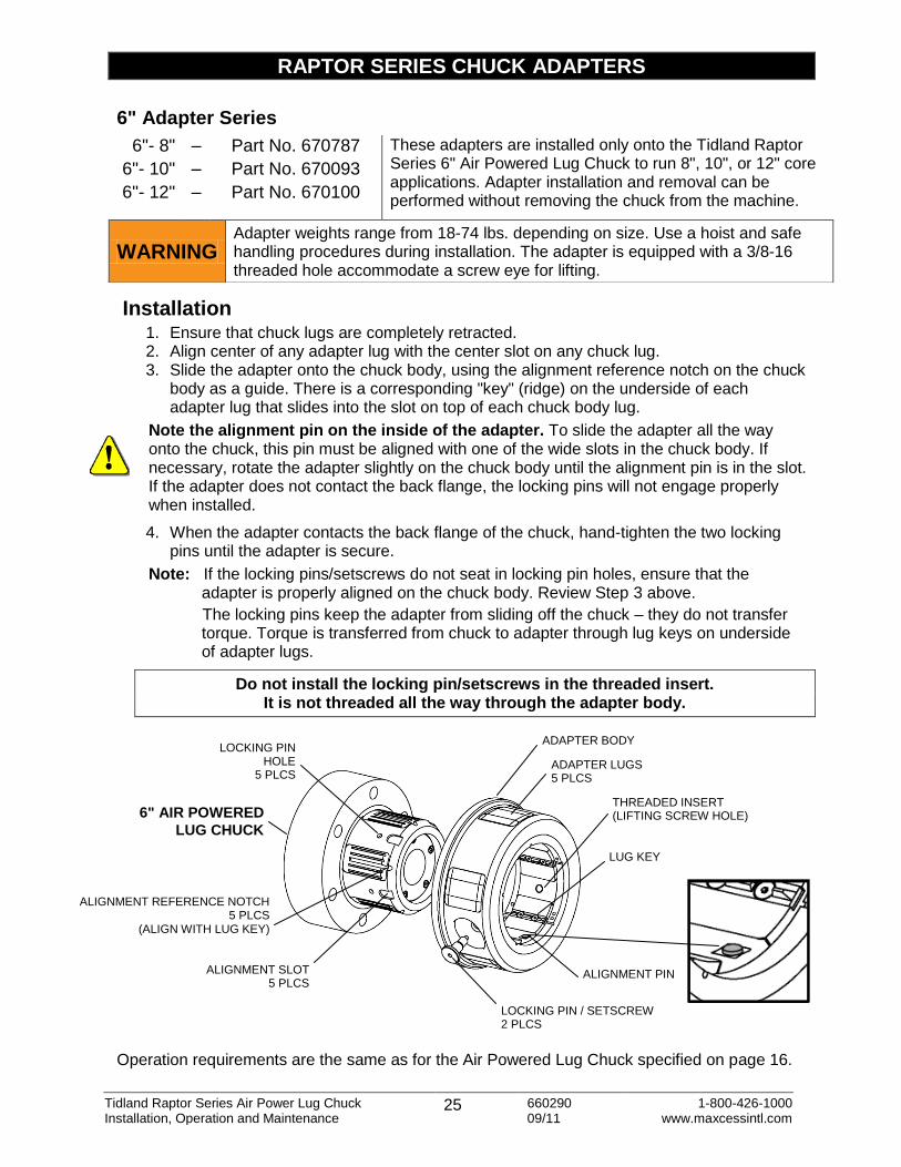
6" Adapter Series
Installation 1. Ensure that chuck lugs are completely retracted. 2. Align center of any adapter lug with the center slot on any chuck lug. 3. Slide the adapter onto the chuck body, using the alignment reference notch on the chuck
body as a guide. There is a corresponding "key" (ridge) on the underside of each adapter lug that slides into the slot on top of each chuck body lug.
Note the alignment pin on the inside of the adapter. To slide the adapter all the way onto the chuck, this pin must be aligned with one of the wide slots in the chuck body. If necessary, rotate the adapter slightly on the chuck body until the alignment pin is in the slot. If the adapter does not contact the back flange, the locking pins will not engage properly when installed.
4. When the adapter contacts the back flange of the chuck, hand-tighten the two locking pins until the adapter is secure.
Note: If the locking pins/setscrews do not seat in locking pin holes, ensure that the adapter is properly aligned on the chuck body. Review Step 3 above.
The locking pins keep the adapter from sliding off the chuck – they do not transfer torque. Torque is transferred from chuck to adapter through lug keys on underside of adapter lugs.
Do not install the locking pin/setscrews in the threaded insert. It is not threaded all the way through the adapter body.
Operation requirements are the same as for the Air Powered Lug Chuck specified on page 16.
6"- 8" – Part No. 670787 These adapters are installed only onto the Tidland Raptor Series 6" Air Powered Lug Chuck to run 8", 10", or 12" core applications. Adapter installation and removal can be performed without removing the chuck from the machine.
6"- 10" – Part No. 670093
6"- 12" – Part No. 670100
WARNING Adapter weights range from 18-74 lbs. depending on size. Use a hoist and safe handling procedures during installation. The adapter is equipped with a 3/8-16 threaded hole accommodate a screw eye for lifting.
ALIGNMENT PIN ALIGNMENT SLOT 5 PLCS
ALIGNMENT REFERENCE NOTCH 5 PLCS
(ALIGN WITH LUG KEY)
THREADED INSERT (LIFTING SCREW HOLE)
LUG KEY
6" AIR POWERED
LUG CHUCK
LOCKING PIN HOLE
5 PLCS
LOCKING PIN / SETSCREW 2 PLCS
ADAPTER LUGS 5 PLCS
ADAPTER BODY
Tidland Raptor Series Air Power Lug Chuck 26 660290 1-800-426-1000 Installation, Operation and Maintenance 09/11 www.maxcessintl.com
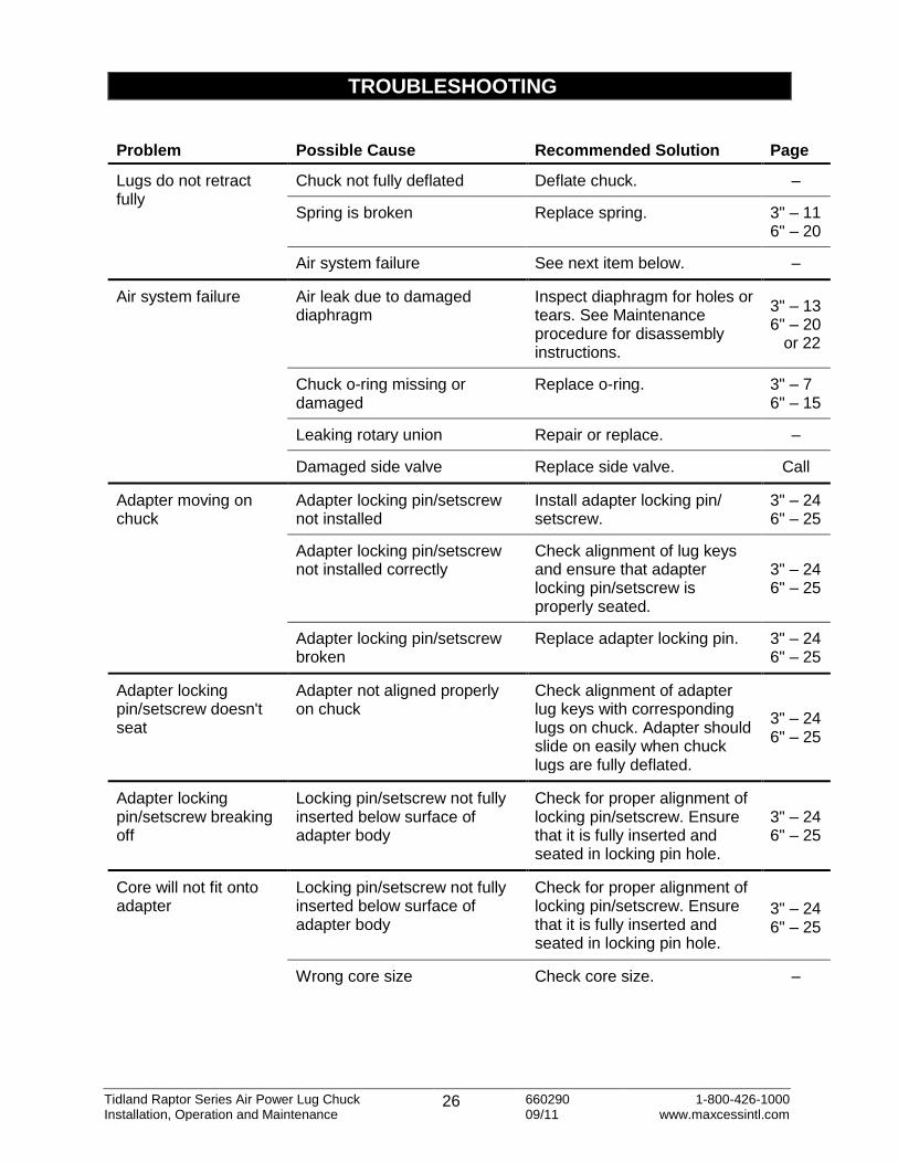
TROUBLESHOOTING
Problem Possible Cause Recommended Solution Page
Lugs do not retract fully
Chuck not fully deflated Deflate chuck. –
Spring is broken Replace spring. 3" – 11 6" – 20
Air system failure See next item below. –
Air system failure Air leak due to damaged diaphragm
Inspect diaphragm for holes or tears. See Maintenance procedure for disassembly instructions.
3" – 13 6" – 20 or 22
Chuck o-ring missing or damaged
Replace o-ring.
3" – 7 6" – 15
Leaking rotary union Repair or replace. –
Damaged side valve Replace side valve. Call
Adapter moving on chuck
Adapter locking pin/setscrew not installed
Install adapter locking pin/ setscrew.
3" – 24 6" – 25
Adapter locking pin/setscrew not installed correctly
Check alignment of lug keys and ensure that adapter locking pin/setscrew is properly seated.
3" – 24 6" – 25
Adapter locking pin/setscrew broken
Replace adapter locking pin. 3" – 24 6" – 25
Adapter locking pin/setscrew doesn't seat
Adapter not aligned properly on chuck
Check alignment of adapter lug keys with corresponding lugs on chuck. Adapter should slide on easily when chuck lugs are fully deflated.
3" – 24 6" – 25
Adapter locking pin/setscrew breaking off
Locking pin/setscrew not fully inserted below surface of adapter body
Check for proper alignment of locking pin/setscrew. Ensure that it is fully inserted and seated in locking pin hole.
3" – 24 6" – 25
Core will not fit onto adapter
Locking pin/setscrew not fully inserted below surface of adapter body
Check for proper alignment of locking pin/setscrew. Ensure that it is fully inserted and seated in locking pin hole.
3" – 24 6" – 25
Wrong core size Check core size. –


All rights reserved. No part of this publication may be reproduced, transmitted, transcribed, stored in a retrieval system, or translated into any language in any form by any means without the written permission of Tidland.
NORTH AMERICA Toll Free 800.639.3433
Tel +1.405.755.1600 Fax +1.405.755.8425
[email protected] www.maxcessintl.com
EUROPE Tel +49.6195.7002.0
Fax +49.6195.7002.933 [email protected] www.maxcess.eu
CHINA Tel +86.756.881.98398 Fax +86.756.881.9393
[email protected] www.maxcessintl.com.cn
KOREA, TAIWAN, AND SE ASIA
Tel +65.9620.3883 Fax +65.6235.4818
SOUTH AMERICA Tel +55.11.3959.0990 Fax +55.11.3856.0990
[email protected] www.maxcessintl.com.br
INDIA Tel +91.22.27602633 Fax +91.22.27602634
[email protected] www.maxcess.in
JAPAN Tel +81.43.421.1622 Fax +81.43.421.2895
[email protected] www.maxcess.jp
© 2011 Maxcess 660290M 09/11