Embed Size (px)
Citation preview

Rapidmain Installation Guide
Air Controls and Compressors LtdTrafalgar Court, Waterloo Ind Estate, Widnes Cheshire. UK.
Web: www.accltd.com. Telephone 0151 423 1750.
Aluminium Compressed Air Pipe Work Installation Guide
Ref: Rapidmain installation guide 4b
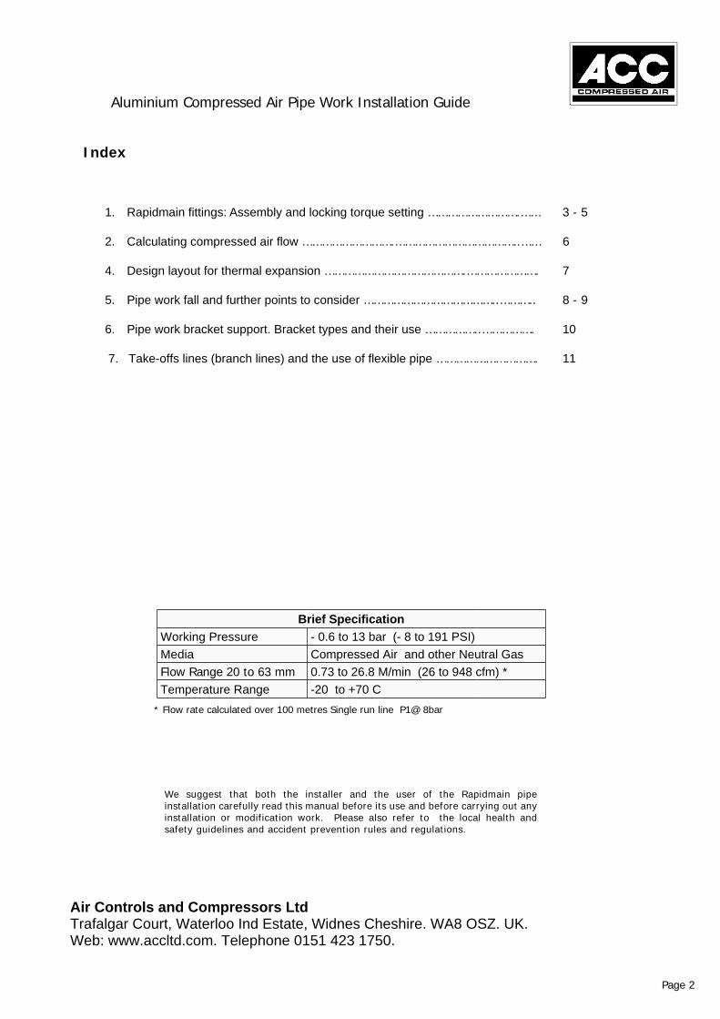
Index
1. Rapidmain fittings: Assembly and locking torque setting ……………………….…… 3 - 5
2. Calculating compressed air flow ……………………….………………………………..…… 6
4. Design layout for thermal expansion …………………………………….…………………. 7
5. Pipe work fall and further points to consider …………………………………..……….. 8 - 9
6. Pipe work bracket support. Bracket types and their use ……………..……………. 10
7. Take-offs lines (branch lines) and the use of flexible pipe …………………………. 11
Aluminium Compressed Air Pipe Work Installation Guide
Air Controls and Compressors LtdTrafalgar Court, Waterloo Ind Estate, Widnes Cheshire. WA8 OSZ. UK.Web: www.accltd.com. Telephone 0151 423 1750.
* Flow rate calculated over 100 metres Single run line P1@ 8bar
Page 2
Brief SpecificationWorking Pressure - 0.6 to 13 bar (- 8 to 191 PSI)Media Compressed Air and other Neutral GasFlow Range 20 to 63 mm 0.73 to 26.8 M/min (26 to 948 cfm) *Temperature Range -20 to +70 C
We suggest that both the installer and the user of the Rapidmain pipeinstallation carefully read this manual before its use and before carrying out anyinstallation or modification work. Please also refer to the local health andsafety guidelines and accident prevention rules and regulations.

Tightening of locking collars on fittings
Assemble by hand or use our spanner set the correct torque. Black for the body and bluefor the nut: See table B below
Use the depth gauge on the spanner to markthe outside of the pipe: See below.
Air Controls and Compressors LtdTrafalgar Court, Waterloo Ind Estate, Widnes Cheshire. WA8 OSZ. UK.Web: www.accltd.com. Telephone 0151 423 1750.
Rapidmain Installation GuideAluminium Compressed Air Pipe Work Installation
Rapidmain fittings: Assembly and locking torque settings
Page 3
Push the fitting up to the mark on thepipe and then rotate the blue locknutto secure.
Table B
O D 20 25 32 40 50 63Torque 9 -11 11-13 12 - 15 15- 17 17 - 20 18 - 22L = mm 45 55 60 70 85 95

Rapidmain Installation Guide
Air Controls and Compressors LtdTrafalgar Court, Waterloo Ind Estate, Widnes Cheshire. WA8 OSZ .UK.Web: www.accltd.com. Telephone 0151 423 1750.
On larger pipe if required use a neutral lubricant or soap.
If you choose to use a vice to clamp the Aluminium pipe when cutting or chamfering leaveclear at least 50mm of pipe to avoid damaging the radius diameter and pipe sealing surface.
Aluminium Compressed Air Pipe Work Installation Guide
Chamfer Pipe
Rapidmain fittings: Assembly and locking torque settings
Page 4

____________________________________________________________________________
Rapidmain fittings: Assembly and locking torque settings
WARNING: to avoid O-Ring damage, the tube end must be chamfered before insertingthe tube into the fittings.
R-Range of Compressed Air distribution fittings Sizes DN 20 to 63 OD
1.1 Before use check that all the fitting connection parts are correctly assembled. Ensure youcheck the orientation of the locking clip; if this is incorrectly assembled the integrity of theconnection cannot be guaranteed (See Table A).
1.2 Before inserting the tube into the fitting rotate the light-blue coupling ring until a slightmechanical stop is felt and no further.
1.3 The tube must be inserted into the fitting until the tube bottoms. This can be checked bypreviously marking on the tube the length “L” indicated in Table B.
1.4 Once the tube has been correctly inserted into the fitting, rotate the coupling ringcompletely over the first mechanical stop described in Section 1.2 above until fully tight.For best results it is advisable to use the “C” type spanners shown in the catalogue.
1.5 Table B shows the torque (N/m) required for each fitting size to provide the optimummechanical operation and seal.
1.6 Table C illustrates the correct alignment for installation. Misalignment of more than 5o
from the horizontal could compromise the integrity of the fitting seal.
1.7 Please refer to the specifications shown in the present catalogue for pipe and fittingscompatibility with chemical substances that could be present in the compressed air.
1.8 Rapidmain will not be held responsible for any damage caused by improper use of theirproducts and/or non-compliance of the manufacturers assembly instructions here within.
How to calculate an air system pipe size
2.1 Pressure drop through fittingsAlthough fittings are smooth inside and have the same tube internal diameter, theynonetheless cause a resistance to air flow, particularly when tubes change direction as inthe case of elbows, tees, couplings and reduction fittings. Table E refers to pressuredrops caused by fittings. Every fitting or change of direction has an equivalent pipelength of tube indicated in this table.
2.2 Air System pipe sizing Once the compressed air consumption (l/min) and the allowablepressure drop havebeen calculated, refer to Table D to select the correct tube dimension. After havingexamined the plant and considered the changes of direction as well as the pressure dropof fittings you can then refer to Table E to complete and correct previous calculations.
Air Controls and Compressors LtdTrafalgar Court, Waterloo Ind Estate, Widnes Cheshire. WA8 OSZ. UK.Web: www.accltd.com. Telephone 0151 423 1750.
Table A
Page 5

Table C
Table D
Pressure drop for100 m (in bars)
Delivery SRA*
(in l/min)
Outsidediameter of
the tube(mm)
Referentialaxis
Pressure(in bars)
Effe
ctiv
e
Abso
lute
Delivery SRA*
Actual delivery at the effective pressure (P) x absolute pressure (P+1) in bars
Temperature Correction:0 degrees + 273 Air
delivery at 0 degrees C = delivery 15 degrees C x ________________
288*SRA: Standard Reference Atmosphere
Using the Nomogram
The tube diameter can be determined by first finding the flow rate in l/m and the allowablepressure drop.
a. We have chosen the working pressure on the “C” axis. A straight red line has thenbeen drawn connecting the working pressure to the pressure drop value on the “A” axis.
b. Drawing this straight line allows us to locate a point on the “R” referential axis.c. A green line has then been drawn from the referential “R” axis to the value on the
“A” axis which indicates plant delivery in l/min.d. This green line intersects on the “B” axis which shows the suitable tube diameter.
Aluminium Compressed Air Pipe Work Installation Guide
Air Controls and Compressors LtdTrafalgar Court, Waterloo Ind Estate, Widnes Cheshire. WA8 OSZ .UK.Web: www.accltd.com. Telephone 0151 423 1750.
Calculating Compressed air flow
Page 6

Introduction
The theoretical calculations and design criteria in thismanual are only relevant where the installationambient temperature is between 15 oC and 25oC.
Attention! Where the installation is outside of therecommended ambient temperatures indicated above,it may be necessary to take corrective action such asthermal insulation of the pipe or the inclusion ofexpansion/contraction loops.
Variation due tothermal expansion
Calculating expansion loop dimensionsOn long straight runs of pipe it may be necessary toinsert expansion loops in the line to prevent damageto the pipe, due to thermal movement (expansion orcontraction) of the pipe.
LegendA-B = Quote (mm)L-L1-L2 = Lengths (mt)DL = Expansions (mm)DT = Thermal range (oC)M = Mobile bracketF = Fix bracket
ExampleL1 = 40 mt L2 = 40 mt DT = 50oCDL = DT x 0.02 x L = 50 x 0.02 x 40 = 40mm A = DL x 23 = 40 x 23 = 920 mmB = 0.7 x A = 0.7 x 920 = 640 mm
DL = DT x 0,02 x LA = DL x 23B = 0.7 x A
“Fixed brackets” hold the pipe firmly while “sliding brackets” allow axial movement.
Examples of Expansion Loops
Vertical layout (Upwards)
Vertical layout (Downwards)
Horizontal
Aluminium Compressed Air Pipe Work Installation Guide
Air Controls and Compressors LtdTrafalgar Court, Waterloo Ind Estate, Widnes Cheshire. WA8 OSZ. UK.Web: www.accltd.com. Telephone 0151 423 1750.
Design layout for thermal expansion
Page 7

Fall of pipes
Where possible horizontal runs should be designed to have a slight fall of (1-2%) in the directionof air flow to encourage drainage and collection of condensate at lower levels or at drop legsbuilt within the air system, from which the condensate can be drained as required.
Install drains at low points where ever possible.
Example
Pipe Fall
Aluminium Compressed Air Pipe Work Installation Guide
Air Controls and Compressors LtdTrafalgar Court, Waterloo Ind Estate, Widnes Cheshire. WA8 OSZ.UK. Web: www.accltd.com. Telephone 0151 423 1750.
Pipe work fall and further points to consider
Page 8
Direction of air flow

To allow for system maintenance, install an adequate quantity of isolation valves in the pipe work.
Ball Valve
Valve
Fixing of Pipes
To allow for thermal movement of the pipe and to avoid stress points, the pipe should be installedand fixed to a secure surface of building, such as a wall, brickwork, roof support (direct or withhanging brackets) or the building framework using suitable “fixed and sliding brackets ” as required.
Fixedbracket
Fixed bracket
Sliding bracket
Fixedbracket
Aluminium Compressed Air Pipe Work Installation Guide
Air Controls and Compressors LtdTrafalgar Court, Waterloo Ind Estate, Widnes Cheshire. WA8 OSZ. UK.Web: www.accltd.com. Telephone 0151 423 1750.
Pipe work fall and further points to consider
Page 9

Bracket and Pipe support centresIt is important to install the pipe work brackets with correct spacing. Always try tosupport the pipe joint with a bracket located within 200 to 500 mm from the pipe joint.Please refer to the diagram below for examples of preferred installation
LegendL = Length (mt)P = Brackets support centre (mt)M = BracketG = Joint
Suggested Maximum Support Centres)DN 20/25 32 40 50 63P (MT) 2.5 3 3.5 4 4.5
Rapidmain Installation Guide
Install brackets by each joint to supportthe pipe joint
DL = DT x 0,2 x LB = (2 x R) + DL 1 + DL 2
LegendL1-L2 = Lengths (mt)DL1-DL2 = Expansion (mm)DT = Thermal range (oC)M = BracketR = Radius (mm)A-B = Quotes (mm)
Quote R – A (mm)DN 20 25 32 40 50 63R (mm) 70 85 100 130 160 200A (mm) 370 390 500 560 600 800
Attention!Tables are valid only for stainless steel flexible hoses
type 1REX/INOX/N/321/DN.
For other types refer to the manufacturer’stechnical documentation
An alternative to the “standard” aluminium expansion loop,is to use suitable flexible hose assembly as shown below.
Aluminium Compressed Air Pipe Work Installation Guide
Air Controls and Compressors LtdTrafalgar Court, Waterloo Ind Estate, Widnes Cheshire. WA8 OSZ. UK.Web: www.accltd.com. Telephone 0151 423 1750.
Pipe work bracket support. Bracket types and there use
Page10

DL = DT x 0,2 x LA = DL x Y
LegendA = Quote (mm)L1-L2 = Lengths (mt)DL = Expansion (mm)DT = Thermal range (oC)F = Fixed bracketU = UseY = Calculation factor
Calculation Factor YDN 20 25 32 40 50 63Y 20 20 25 28 33 40
Bends using flexible hose.
Using a flexible hose in corners is alsoacceptable. They can be used for the change ofdirection and at the same time to compensatefor any thermal movement.
L min = 1000 mm
LegendL1-L2 = Lengths (mt)DL1-DL2 = Expansion (mm)M = BracketR = Radius (mm)L = Length of flexible pipe (mm)
Avoid installing flexible hoses with to tight a radius or where thehose is subject to, too much stretch
Aluminium Compressed Air Pipe Work Installation Guide
Air Controls and Compressors LtdTrafalgar Court, Waterloo Ind Estate, Widnes Cheshire. WA8 OSZ. UK.Web: www.accltd.com. Telephone 0151 423 1750.
Take-off lines (branch lines) and the use of flexible pipe
At the end of a pipe run alwaysterminate the pipe and the fitting toan fixed anchored point eg: Wall
Page 11
Pd 20od=0.2 b(3 psi) 6m/secPd 63od=2.5%(3 psi) 12m/sec