Embed Size (px)
Citation preview

Global Trajectory Optimization Group
NASA GSFC
Jacob Englander
8-26-2016
Rapid Preliminary Design of Interplanetary Trajectories Using the Evolutionary Mission Trajectory Generator
https://ntrs.nasa.gov/search.jsp?R=20160010632 2018-07-03T05:30:16+00:00Z

Global Trajectory Optimization Group
NASA GSFC
EMTG: The Team
NASA Goddard Space Flight Center
- Jacob Englander
- Jeremy Knittel
- Kyle Hughes
a.i. solutions
- Matthew Vavrina
University of Illinois at Urbana-
Champaign
- Donald Ellison
- Ryne Beeson
- Alexander Ghosh
- Professor Bruce Conway
Catholic University of America
- Bruno Sarli
University of Vermont
- David Hinckley
University of Colorado
- Sean Napier
FBCM
- Arnold Englander
2

Global Trajectory Optimization Group
NASA GSFC
Introduction to the General Interplanetary Mission Design Problem
The interplanetary design problem is composed of both discrete and
real-valued decision parameters:
- Choice of destination(s), number of planetary flybys, identities of flyby
planets
- Launch date, flight time(s), epochs of maneuvers, control history, flyby
altitudes, etc.
For example, for a main-belt asteroid mission, the designer must
choose:
- The optimal asteroid from a set of scientifically interesting bodies
provided by the customer
- Whether or not to perform planetary flybys on the way to the main belt
and, if so, at which planets
- Optimal trajectory from the Earth to the chosen asteroid by way of the
chosen flyby planets
3

Global Trajectory Optimization Group
NASA GSFC
Brief History of Automated Interplanetary Trajectory Design
4
Gage, Braun, and Kroo, 1994 – autonomous chemical design with variable mission
sequence (no deep-space maneuvers)
Vasile and de Pascale, 2005 – autonomous chemical design for fixed mission sequence
Vἰnko and Izzo, 2008 – autonomous chemical design for fixed mission sequence
Wall and Conway, 2009 – autonomous low-thrust design for fixed mission sequence (no
planetary flybys)
Chilan and Conway, 2009 – autonomous low-thrust and chemical design for fixed mission
sequence (no planetary flybys)
Yam, di Lorenzo, and Izzo, 2011 – autonomous low-thrust design for fixed mission
sequence
Abdelkhalik and Gad, 2011, 2012, and 2013 – autonomous chemical design with variable
mission sequence
Englander, Conway, and Williams, 2012 – autonomous chemical design with variable
mission sequence
Englander (dissertation) 2013 – autonomous low-thrust design with variable mission
sequence

Global Trajectory Optimization Group
NASA GSFC
Automated Mission Design via Hybrid Optimal Control
Break the mission design problem into two stages, or “loops”
- “outer-loop” picks sets of destinations, planetary flybys, sizes the
power system, can pick propulsion system – a discrete optimization
problem
- “inner-loop” finds the optimal trajectory for a given candidate outer-
loop solution – a real-valued optimization problem
- For the outer-loop to work, the inner-loop must function autonomously
(i.e. no human interaction)
5

Global Trajectory Optimization Group
NASA GSFC
Multi-Objective Hybrid Optimal Control
The customer (scientist or project manager) most often does not want
just one point solution to the mission design problem
Instead, an exploration of a multi-objective trade space is required
For a typical main-belt asteroid mission the customer might wish to see
the trade-space of:
- Launch date vs
- Flight time vs
- Deliverable mass
- While varying the destination asteroid, planetary flybys, solar array
size, etc
To address this question we use a multi-objective discrete outer-loop
which defines many single objective real-valued inner-loop problems
6

Global Trajectory Optimization Group
NASA GSFC
Mission and Systems Design via Hybrid Optimal Control
The interplanetary mission design problem has two types of
variables:
Discrete variables encoding the mission sequence and choice of
spacecraft systems (launch vehicle, power, propulsion)
Continuous variables defining the trajectory
In Hybrid Optimal Control, the problem is divided into two nested
loops.
- The outer-loop solves the discrete problem and identifies candidate
missions.
- The continuous inner-loop then finds the optimal trajectory for each
candidate mission.
7

Global Trajectory Optimization Group
NASA GSFC
Outer-Loop Transcription and Optimization
The outer-loop finds the non-dominated trade surface between any set
of objective functions chosen by the user
Non-dominated surface means “no point on the surface is superior to
any other point on the surface in all of the objective functions”
The outer-loop solver may choose from a menu of options for each
decision variable
The choices made by the outer-loop solver are used to define trajectory
optimization problems to be solved by the inner-loop
8

Global Trajectory Optimization Group
NASA GSFC
Discrete Optimization of the Mission Sequence and Spacecraft Systems
EMTG’s outer-loop finds the non-dominated set of missions, those
which are not strictly better or worse than other missions in the set
based on all of the analyst’s chosen objective functions
EMTG uses a version of the Non-Dominated Sorting Genetic
Algorithm II (NSGAII) which can evolve to the final non-dominated
trade front despite starting from complete randomness. No a priori
knowledge of the solution is required.
9

Global Trajectory Optimization Group
NASA GSFC
Trajectory Optimization via Monotonic Basin Hopping and Nonlinear Programming
EMTG’s inner-loop finds the optimal trajectory using a stochastic
global search method called Monotonic Basin Hopping (MBH)
coupled with a gradient-based local search supplied by the third-party
Sparse Nonlinear Optimizer (SNOPT).
EMTG does not require an initial guess and can find the global
optimum autonomously.
10

Global Trajectory Optimization Group
NASA GSFC
Chemical Mission Modeling in EMTG
11
M. Vavrina and J. Englander, “Global Optimization Of
N-maneuver, High-thrust Trajectories Using Direct
Multiple Shooting,” AAS Space Flight Mechanics
Meeting, Napa, CA, February 2016.

Global Trajectory Optimization Group
NASA GSFC
Name SMA ECC INC RAAN AOP
2100 Ra-Shalom 0.83 0.44 15.76 170.84 356.04
3671 Dionysus 2.2 0.54 13.55 82.16 204.2
3691 Bede 1.77 0.28 20.36 348.77 234.88
14402 1991DB 1.72 0.4 11.42 158.26 51.32
15817 Lucianotesi 1.32 0.12 13.87 162.52 94.3
16064 Davidharvey 2.85 0.59 4.54 335.61 104.84
65706 1992NA 2.4 0.56 9.71 349.38 8.1
85774 1998UT18 1.4 0.33 13.59 64.71 50.01
136793 1997AQ18 1.15 0.47 17.38 296.3 36.98
141079 2001XS30 1.16 0.83 28.53 251.47 0.87
152563 1992BF 0.91 0.27 7.27 315.57 336.3
152679 1998KU2 2.25 0.55 4.93 205.79 120.28
162173 1999JU3 1.19 0.19 5.88 251.61 211.43
162567 2000RW37 1.25 0.25 13.75 333.34 133.26
175706 1996FG3 1.05 0.35 1.99 299.73 23.99
308635 2005YU55 1.16 0.43 0.34 35.89 273.63
322775 2001HA8 2.39 0.53 11.48 95.89 202.37
370061 2000YO29 1.81 0.69 54.6 262.66 309.32
413123 2001XS1 2.67 0.56 10.93 266.97 164.88
1997 AC11 0.91 0.37 31.64 116.94 141.62
1998 HT31 2.52 0.69 6.8 213.91 80.42
1999 VN6 1.73 0.37 19.48 58.1 43.56
2000 WL10 3.14 0.72 10.24 252.16 115.12
2001 SJ262 2.94 0.58 10.8 210.44 164.93
2002 DH2 2.05 0.54 20.94 345.56 231.79
12
High-Thrust Example: Whack-a-Rock
In the “Whack-a-Rock” problem we
design a small bodies mission
which delivers a high-speed
impactor to a Near Earth Object
(NEO) and then returns to
rendezvous and perform detailed
science some years later.
All C-type NEOs with diameter of
500m or greater are admissible
targets and are considered equally
scientifically valuable.
Planetary flybys can be added as
appropriate.
We want to know what the best C-
type NEO is for this mission during
the 2020s.

Global Trajectory Optimization Group
NASA GSFC
Whack-a-Rock Problem Assumptions
13
Description Value
Launch year outer-loop chooses in [2020, 2029]
Flight time outer-loop chooses in [3, 12] years
Launch vehicle
outer-loop chooses Atlas V 401, 411, 421, 431, 541,
or 551
Spacecraft Isp 320 s
Penetrator mass 20 kg
Arrival conditions
(first Journey) intercept with v∞ in [5.0, 10.0] km/s, θillumination ≤ 70˚
(second Journey) rendezvous
Number of flybys allowed 2 in each Journey
Flyby targets considered Venus, Earth, Mars
Outer-loop objective
functions launch year
flight time
delivered mass
launch vehicle choice
Outer-loop population size 256
Outer-loop mutation rate 0.3
Inner-loop MBH run-time 10 minutes
Inner-loop MBH Pareto α 1.3

Global Trajectory Optimization Group
NASA GSFC
Whack-a-Rock: First Generation Trade Space
14

Global Trajectory Optimization Group
NASA GSFC
Whack-a-Rock: Final Generation Trade Space
15

Global Trajectory Optimization Group
NASA GSFC
Whack-a-Rock: Example Trajectories
16
Atlas V 421, 11.25 year flight time Atlas V 551, 2.45 year flight time

Global Trajectory Optimization Group
NASA GSFC
Interlude: What makes Low-Thrust Different?
17
Low-thrust electric propulsion is characterized by high power requirements but
also very high specific impulse (Isp), leading to very good mass fractions
Low-thrust trajectory design is a very different process from chemical trajectory
design
- Like chemical design, must find the optimal launch date, flight time, and dates
of each flyby (if applicable)
- Unlike chemical design, must find a time-history of thrust control for the entire
mission
Low-thrust electric propulsion mission design requires accurate modeling
of propulsion and power systems. Every spacecraft design drives a
unique trajectory design!

Global Trajectory Optimization Group
NASA GSFC
Traditional Methods of Low-Thrust, Multi-Flyby Trajectory Design
Several methods of picking the destination and flyby sequence:
- Grid search over all possible choices of destinations, flyby sequence,
propulsion system, power system, etc. (very expensive and often
impractical)
- Intuition-guided manual design of the trajectory (even more expensive,
can miss non-intuitive solutions)
Several methods of designing the trajectory:
- Local optimization from an initial guess provided by a chemical
mission design (but sometimes the optimal chemical trajectory does
not resemble the optimal low-thrust trajectory)
- Local optimization from an initial guess provided by a low-fidelity
approximation to the low-thrust model, i.e. shaped-based methods
(but sometimes the shape-based method cannot accurately
approximate the true trajectory)
18

Global Trajectory Optimization Group
NASA GSFC
Low-Thrust Modeling in EMTGTranscription
19
J. Englander and B.Conway, “An
Automated Solution of the Low-
Thrust Interplanetary Trajectory
Problem,” AIAA Journal of
Guidance, Control, and
Dynamics, accepted 2016.
Break mission into phases. Each phase starts and ends at a body.
Sims-Flanagan Transcription
- Break phases into time steps
- Insert a small impulse in the center of each
time step, with bounded magnitude
- Optimizer Chooses:
Launch date
- For each phase:
Initial velocity vector
Flight time
Thrust-impulse vector at each time step
Mass at the end of the phase
Terminal velocity vector
Assume two-body force model; propagate by solving Kepler’s problem
Propagate forward and backward from phase endpoints to a “match point”
Enforce nonlinear state continuity constraints at match point
Enforce nonlinear velocity magnitude and altitude constraints at flyby

Global Trajectory Optimization Group
NASA GSFC
Low-Thrust Modeling in EMTGSpacecraft and Launch Vehicle Models
20
• Medium-fidelity mission design requires accurate hardware modeling
• Launch vehicles are modeled using a polynomial fit
𝑚𝑑𝑒𝑙𝑖𝑣𝑒𝑟𝑒𝑑 = 1 − 𝜎𝐿𝑉 𝑎𝐿𝑉𝐶35 + 𝑏𝐿𝑉𝐶3
4 + 𝑐𝐿𝑉𝐶33 + 𝑑𝐿𝑉𝐶3
2 + 𝑒𝐿𝑉𝐶3 + 𝑓𝐿𝑉where 𝜎𝐿𝑉 is launch vehicle margin and 𝐶3 is hyperbolic excess velocity
• Thrusters are modeled using either a polynomial fit to published thrust and mass flow
rate data
𝑚 = 𝑎𝐹 𝑃4 + 𝑏𝐹 𝑃
3 + 𝑐𝐹 𝑃2 + 𝑑𝐹 𝑃 + 𝑒𝐹
𝑇 = 𝑎𝑇𝑃4 + 𝑏𝑇𝑃
3 + 𝑐𝑇𝑃2 + 𝑑𝑇𝑃 + 𝑒𝑇
or, when detailed performance data is unavailable
𝑇 =2 𝜂𝑃
𝐼𝑠𝑝𝑔0• Power is modeled by a standard polynomial model
𝑃0𝑟2
𝛾0 +𝛾1𝑟+𝛾2𝑟2
1 + 𝛾3𝑟 + 𝛾4𝑟2
1 − 𝜏 𝑡
where 𝑃0 is the power at beginning of life at 1 AU and 𝜏 is the solar array degradation constant

Global Trajectory Optimization Group
NASA GSFC
Asteroid Redirect Robotic Mission: return asteroid boulder or entire asteroid- Extensibility option is to return boulder from Deimos
- Want to understand how return mass & TOF are affected by array size, # of thrusters
4 optimization objectives: max. return mass, min. TOF, min. EOL power, min. # of thrusters (all coupled)
Low-Thrust Example Problem: ARRM
Design Variable Integer Value Resolution
Launch option [0, 1]{Delta IV-H from LV curve,
Delta IV-H with LGA}-
Solar array size [0, 15] [25, 95] kW 5 kW
Launch window
open epoch[0, 9] {8/1/2020, …, 8/1/2030} 1 year
Flight time [0, 26] [700, 3300] days 100 days
Engine mode [0, 2]{high-Isp, medium-thrust, high-
thrust}-
Number of
engines[0, 7] [2, 9] 1
System Design Variables
Description Value
Launch window 1 year
Wait time at Deimos [150, 600] days
Min. spacecraft mass with 2
thrusters & 25 kW array5703.5 kg
Additional dry mass per extra
thruster75 kg
Additional dry mass per kW of
array power above 25 kW12.5 kg
Max. depart. mass if lunar gravity
assist (C3 ≤ 2.0 km2/s2) 11191 kg
Max. departure mass if direct
launch (C3 = 0.0 km2/s2)10796 kg
Maximum C3 if direct launch 6 km2/s2
Lunar DRO insertion ∆V 75 m/s
Thruster duty cycle 90%
Solar array modeling 1/r2
Spacecraft bus power 2 kW
Propellant margin 6%
Notional Mission Parameters
21
207360 possible combinations
Global Trajectory Optimization Group
NASA GSFC
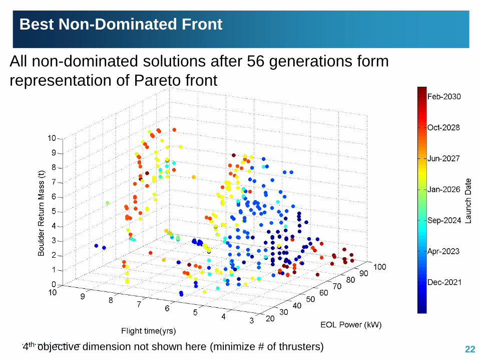
Best Non-Dominated Front
224th objective dimension not shown here (minimize # of thrusters)
All non-dominated solutions after 56 generations form
representation of Pareto front

Global Trajectory Optimization Group
NASA GSFC
Optimal Trade Space
23
• Sharp increase in return mass up to 6 yr TOF
• 2 yr TOF gap along max. return mass
• Higher power enables short TOF solutions
All non-dominated solutions after 56 generations projected in 2D objective space
• High-Isp mode optimal for highest return
mass cases
• High-thrust mode optimal for Short TOF,
low-power cases
High-Isp Engine
High-Thrust Engine
Medium-Thrust Engine

Global Trajectory Optimization Group
NASA GSFC
Optimal Trade Space (continued)
24
• Most solutions only require 2 or 3 thrusters
• Short-TOF enabled by 4 or 5 thrusters
• Some 6-9 thruster cases hidden in plot
All non-dominated solutions after 56 generations projected in 2D objective space
• Increase in array dry mass decreases
available propellant
• Shorter TOFs benefit from higher power

Global Trajectory Optimization Group
NASA GSFC
Trajectory Examples
25
Highest Return Mass Trajectory• 9.6 t boulder return
• 8.3 year TOF
• 50 kW EOL solar array
• High-Isp mode thruster
• 2 thruster strings
• LGA on Earth departure
Shortest TOF Trajectory• 0.6 t boulder return
• 3.3 year TOF
• 95 kW EOL solar array
• Med.-thrust mode thruster
• 5 thruster strings
• LGA on Earth departure

Global Trajectory Optimization Group
NASA GSFC
EMTG Design Capabilities
Propulsion Types
- High-thrust chemical
- Low-thrust electric
Mission Components
- Deep-space maneuvers
- Gravity Assists
- Asteroid Rendezvous/Flyby
- Sample Return/Planetary Landing
- Launch Vehicle selection
Spacecraft Systems
- Power system sizing
- Propulsion system sizing
Mission Objectives
- Maximize science payload
- Minimize flight time
- Visit as many diverse bodies as
possible
- Maximize encounter energy (for
planetary defense)
Operational and Science Constraints
- Atmospheric entry
- Solar distance
- Any other constraints on final orbit
26

Global Trajectory Optimization Group
NASA GSFC
Conclusion
Interplanetary mission design problems, whether using high-thrust
chemical or low-thrust electric propulsion, may be posed as multi-
objective hybrid optimal control problems (HOCP).
The HOCP may be augmented to include spacecraft hardware
parameters such that the trajectory design problem becomes a coupled
mission and systems design problem.
The combination of a multi-objective discrete NSGA-II outer-loop with a
MBH+NLP inner-loop is a very powerful way to explore a mission and
systems trade space in an efficient, automated manner.
Mission design mathematics may easily be automated. Communication
and understanding cannot be. The method presented here allows
analysts to focus their attention on understanding the needs of their
customers (scientists) and the capabilities of the spacecraft while
leaving the repetitive work to the computer.
27

Global Trajectory Optimization Group
NASA GSFC
Thank you to our backers:
NASA Goddard Space Flight Center Independent Research and
Development (IRAD) program
NASA Goddard Space Science Mission Operations (SSMO)
NASA Graduate Student Researchers Program (GSRP)
Illinois Space Grant
Vermont Space Grant
Various customers at Goddard
28

Global Trajectory Optimization Group
NASA GSFC
Thank You
EMTG is available open-source at
https://sourceforge.net/projects/emtg/
29