Embed Size (px)
Citation preview

O.A. VoronovDiamond Materials, Inc., Piscataway, New Jersey
K.W. Street, Jr.Glenn Research Center, Cleveland, Ohio
Raman Scattering in a New Carbon Material
NASA/TM—2010-216346
May 2010
https://ntrs.nasa.gov/search.jsp?R=20100024332 2018-06-25T20:18:13+00:00Z

NASA STI Program . . . in Profi le
Since its founding, NASA has been dedicated to the advancement of aeronautics and space science. The NASA Scientifi c and Technical Information (STI) program plays a key part in helping NASA maintain this important role.
The NASA STI Program operates under the auspices of the Agency Chief Information Offi cer. It collects, organizes, provides for archiving, and disseminates NASA’s STI. The NASA STI program provides access to the NASA Aeronautics and Space Database and its public interface, the NASA Technical Reports Server, thus providing one of the largest collections of aeronautical and space science STI in the world. Results are published in both non-NASA channels and by NASA in the NASA STI Report Series, which includes the following report types: • TECHNICAL PUBLICATION. Reports of
completed research or a major signifi cant phase of research that present the results of NASA programs and include extensive data or theoretical analysis. Includes compilations of signifi cant scientifi c and technical data and information deemed to be of continuing reference value. NASA counterpart of peer-reviewed formal professional papers but has less stringent limitations on manuscript length and extent of graphic presentations.
• TECHNICAL MEMORANDUM. Scientifi c
and technical fi ndings that are preliminary or of specialized interest, e.g., quick release reports, working papers, and bibliographies that contain minimal annotation. Does not contain extensive analysis.
• CONTRACTOR REPORT. Scientifi c and
technical fi ndings by NASA-sponsored contractors and grantees.
• CONFERENCE PUBLICATION. Collected papers from scientifi c and technical conferences, symposia, seminars, or other meetings sponsored or cosponsored by NASA.
• SPECIAL PUBLICATION. Scientifi c,
technical, or historical information from NASA programs, projects, and missions, often concerned with subjects having substantial public interest.
• TECHNICAL TRANSLATION. English-
language translations of foreign scientifi c and technical material pertinent to NASA’s mission.
Specialized services also include creating custom thesauri, building customized databases, organizing and publishing research results.
For more information about the NASA STI program, see the following:
• Access the NASA STI program home page at http://www.sti.nasa.gov
• E-mail your question via the Internet to help@
sti.nasa.gov • Fax your question to the NASA STI Help Desk
at 443–757–5803 • Telephone the NASA STI Help Desk at 443–757–5802 • Write to:
NASA Center for AeroSpace Information (CASI) 7115 Standard Drive Hanover, MD 21076–1320

O.A. VoronovDiamond Materials, Inc., Piscataway, New Jersey
K.W. Street, Jr.Glenn Research Center, Cleveland, Ohio
Raman Scattering in a New Carbon Material
NASA/TM—2010-216346
May 2010
National Aeronautics andSpace Administration
Glenn Research CenterCleveland, Ohio 44135

Acknowledgments
The authors wish to thank John Turner of Cleveland State University and Kenneth Livi of Johns Hopkins University for the NIR Laser Raman spectrum of the diamond material and for the XRD and TEM data, respectively.
Available from
NASA Center for Aerospace Information7115 Standard DriveHanover, MD 21076–1320
National Technical Information Service5301 Shawnee Road
Alexandria, VA 22312
Available electronically at http://gltrs.grc.nasa.gov
Trade names and trademarks are used in this report for identifi cation only. Their usage does not constitute an offi cial endorsement, either expressed or implied, by the National Aeronautics and
Space Administration.
Level of Review: This material has been technically reviewed by technical management.
This report is a formal draft or working paper, intended to solicit comments and
ideas from a technical peer group.
This report contains preliminary fi ndings, subject to revision as analysis proceeds.

NASA/TM—2010-216346 1
Raman Scattering in a New Carbon Material
O.A. Voronov Diamond Materials, Inc.
Piscataway, New Jersey 08854
K.W. Street, Jr. National Aeronautics and Space Administration
Glenn Research Center Cleveland, Ohio 44135
Abstract
Samples of a new carbon material, Diamonite-B, were fabricated under high pressure from a commercial carbon black – identified as mixed fullerenes. The new material is neither graphite-like nor diamond-like, but exhibits electrical properties close to graphite and mechanical properties close to diamond. The use of Raman spectroscopy to investigate the vibrational dynamics of this new carbon material and to provide structural characterization of its short-, medium- and long-range order is reported. We also provide the results of investigations of these samples by high-resolution electron microscopy and X-ray diffraction. Hardness, electrical conductivity, thermal conductivity and other properties of this new material are compared with synthetic graphite-like and diamond-like materials, two other phases of synthetic bulk carbon.
1.0 Introduction
Raman scattering is very informative for studying carbon materials because each distinct form of carbon has a unique Raman spectrum. In particular, Raman spectroscopy has proven to be extremely sensitive to short, - medium, - and long-range order in solid carbon and has become a standard technique in characterizing carbon materials (Ref. 1).
The temperature-pressure state diagram of carbon (Ref. 2) is not well developed, since carbon has the highest melting and boiling temperatures of all the elements. The critical parameters (Pcr., Tcr., Vcr) of carbon are unknown. There is data regarding the triple point, which is located in the pressure range that exceeds atmospheric pressure (Ptr~10 MPa), indicating that carbon materials sublimate at ambient pressure without melting. Recently a new line of fullerenes and nanotube-based bulk carbon materials has been developed (Ref. 3). We will show later that these new carbon materials are neither graphite-like nor diamond-like carbon. These pure carbon materials will be referred hereafter as “Diamonites” (Ref. 4). Diamonite-A is polymerized under high pressure from fullerene C60 powder precursor; Diamonite-B is derived from “mixed fullerenes” powder; Diamonite-C is a composite carbon-carbon material sintered under pressure from mixed fullerenes and diamond powders; and Diamonite-D is a composite carbon-carbon material synthesized from mixed fullerenes and graphitic powders or fibers. “Mixed fullerenes” powder is a commercial product containing a mixture of various fullerenes.
Diamonite-A and Diamonite-B are new synthetic high-hardness carbon materials with several desirable properties. Both are formed by high-pressure high-temperature consolidation of different types of carbon black. Diamonites are pure carbon materials, but they can also be doped with hydrogen, boron, or nitrogen for electronic applications. Diamonites are much harder and tougher than carbon-graphitic materials. Moreover, Diamonite-B has the same extremely high energy and temperature of sublimation as any carbon material which may lead to interesting engineering applications. Development of new Diamonites using carbon black or soot will result in interesting mechanical and electrical properties, in

NASA/TM—2010-216346 2
combination with high hardness and high toughness. For example, the Diamonite-B material can be readily polished to a high-level mirror quality finish with unusual optical properties that are yet to be explored.
The purpose of this article is to produce a basic template for identifying and understanding the Raman signatures of new carbon materials, such as the Diamonites. The method of sample fabrication for various bulk carbon materials is outlined. This is followed by a comparison of the Raman spectroscopy of the mixed fullerene derived material sample to those of graphitic material and pure diamond material also sintered at our facility. The results of Raman spectra from the surface of this new carbon material and synthetic graphite and diamond materials are summarized along with their key physical properties.
2.0 Experimental Procedures
2.1 Preparation of Samples
For this research, samples of graphite material, diamond material and the new carbon material, Diamonite-B were synthesized. The Diamonite-B is sintered under high pressure from a mixture of fullerenes (“buckyball” structures of carbon atoms, possibly containing “single-wall nanotubes with closed ends” structures (Ref. 5)) which was used as received (Alfa AESAR, Ward Hill, MA). The graphite material was machined from industrial-grade rod. Specimens of the graphite material and Diamonite-B were approximately 9 mm in diameter and 3 mm in height while the specimen of the diamond material was approximately 7 mm in diameter and 3 mm in height. For model comparison, a sample of Diamonite-A was sintered at the same parameters and conditions as the Diamonite-B from pure C60 fullerene which was used as received (Alfa AESAR, Ward Hill, MA). The sintering conditions are described in the literature for preparation of the Diamonite-A (Ref. 3). Below is a summary of Diamonites preparation, including the preparation of powders, agglomeration and co-agglomeration of powders, making of “green bodies”, high pressure sintering, mechanical machining, and lapping or polishing of surfaces to a mirror finish. The green bodies for the Diamonites can be consolidated at 1 MPa-0.5 GPa at room temperature. The mixed fullerenes powder behaves quite differently from C60 powder in cold compaction in that the mixed fullerene powder is harder and needs more careful handling.
The mixed fullerenes powder was milled and compacted in a steel die at room temperature under a pressure of 0.5 GPa. The resulting “green body” is very soft, non-conductive, and has an apparent density of 1.57 g/cm3. The green body was sintered at P = 1.0 GPa and T = 600 °C, with holding time of 15 min. in order to produce Diamonite-B. The samples of Diamonite-B and Diamonite-A fabricated using the same parameters were harder than steel, electrically conductive, and had a pitch black mirror-like cleavage surface (Ref. 4). The samples of synthetic diamond material were sintered at P = 8.0 GPa and T = 1600 °C, with a holding time of 1 min. The grains of the initial synthetic diamond powder for synthesizing the diamond material were a mono-crystalline structure approximately 50 μm in diameter; the majority of grains were in the 40 to 60 μm range. The filled density of this diamond powder was 1.91 g/cm3. A High Pressure and High Temperature (HPHT) Apparatus described in the literature (Ref. 6) was used to fabricate samples. In the hydraulic unit of the apparatus a pump supplies oil to the cylinder under pressure (P*). Area (S*) of the ram cross-section multiplied by pressure in the cylinder gives the value of force after deducting friction (Ffr) between the ram and cylinder: F = P* S* - Ffr (1) The force is applied to the HP unit, which is inserted into the frame of the press. Pressure is generated in the HP unit as the clay container is squeezed by the anvils. The pressure is generated at room temperature. Values of pressure in the center of the container can be evaluated by formula (2): P = F/(S + F/H) (2)

NASA/TM—2010-216346 3
where H is micro-hardness of the working parts of the anvils (H = 15 GPa for the cermet of the first modification and H = 10 GPa for hardened steel in the second modification), and S is the effective area of the container.
Temperature is generated by a graphite heater inside the container. Temperature is approximated by Equation (3) if it is not too high: T = T0+kW (3) where T0 is ambient temperature, W = UI is power to the heater, k is a proportionality coefficient, U is the voltage, and I is the current. Equation (3) is valid when heat dissipation is mostly by thermal conductivity. At higher temperatures, when radiation becomes important, the value of the temperature is lower than that determined from Equation (3). The dependences of pressure on force and temperature on power were carefully calibrated by known phase and state transitions, so these values could be determined with high precision.
All samples were sintered inside industrial synthetic graphite material crucibles encased in clay containers. Sintered samples were extracted from opened crucibles and fragments of crucibles and the clay containers were discarded. Machined samples of synthetic diamond material were boiled in perchloric acid, then in distilled water and dried. Samples of Diamonites were cleaned in acetone and dried.
2.2 Raman Instrumentation
“Combined scattering of light” or “secondary radiation” was discovered in 1928 by Landsberg and Mandelshtam (Ref. 7) from the surface of solids and by Raman and Krishnan (Ref. 8) from the surface of liquids. Specificity of spectra provides a means to determine vibrational symmetry, symmetry of molecules, or bonds in solid substances, and to identify specific molecules or solid particles in the mixture (Ref. 9).
A Renishaw Model 2000 Raman Microscope that uses a 25 mW Ar Ion laser operating at 514.5 nm was employed to collect Raman spectra. Approximately 6 mW is incident upon the sample due to losses in the optics of the system. Spectra were acquired in extended scan mode from 400 to 4000 cm–1 using an integration time typically between 20 and 100 sec. The microscope objective employed was typically 20X with occasional spectra taken at 10X or 50X having spot diameters of 14, 28, and 5 m, respectively. The spectra presented here are single background corrected scans with minimal Fourier transform smoothing. Spectra were taken from at least three areas of each sample to ensure that the spectra are representative. Because the use of high laser powers is known to alter carbon materials, spectra were also acquired at various integration times to ascertain damage to the samples. Similar equipment, but with a red laser was employed to collect Raman spectra of the diamond sample. The diamond material produces a strong fluorescence background making it difficult to obtain a spectrum, but excitation by a 785 nm red laser did allowed acquisition of the spectrum in the first order region.
A custom backscattering Raman imaging spectrograph employing 785 nm laser excitation and a near infrared optimized, back illuminated liquid nitrogen cooled charge coupled detector was used to acquire the spectrum for the diamond material which fluoresced too strongly for the argon ion laser stimulation. The fluorescence background was corrected to obtain a clean Raman spectrum.
3.0 Experimental Results
3.1 Raman Characterization of the New Carbon Material
The Raman spectrum from the surface of the new mixed fullerenes derived bulk carbon nano-material (Diamonite-B) is shown on Figure 1(a). There are only three very broad peaks. [Subsequently peaks will be identified by a two digit subscript (i,j) where the first digit, i, describes the region of the spectrum

NASA/TM—2010-216346 4
where the peak appears as defined in Table 1 and the second digit, j, describes the order of appearance of the peak from lower to higher inversed wavelength.] The first two peaks are located in the 985 to 1800 cm–1 range with two maximums that can be recognized and identified at 1353 cm–1 (1,1) (also known as the “Disorder” or “D” peak) and 1576 cm–1 (1,2) (also referred to as the first order E2g peak or “G” peak). The intensity of the first maximum is approximately the same as the intensity of the second peak in the deconvoluted spectrum; however, the integrated band intensity ratio depends highly on the spectral bandwidth (I1,2/I1,1 = 0.51). The third peak is located in the second order region, 2315 to 3338 cm–1 (2) with one apparent maximum at 2877 cm–1 (2,1). This third peak is most probably a combination of smaller peaks normally appearing in this region as seen in the graphite material spectrum. This range is where the second order E2g peak would normally be located, around 2700 cm–1. The Intensity of the second order E2g peak is considerably smaller than the peaks in the first order region and is buried amongst other small peaks often appearing in this region as in Figures 1(b) and (c) (Ref. 10).
A similar spectrum for the synthetic graphite material is shown on Figure 1(b). The spectrum for the diamond material (Fig. 2(b)) was corrected for the strong fluorescence background in Figure 2(a). Unlike the Raman spectra of Diamonite-B and synthetic graphite material which are easily observed by stimulation with a visible wavelength laser (green), the diamond material produces a strong fluorescence background making it difficult to obtain a spectrum. Excitation by a 785 nm red laser allowed acquisition of the spectrum in the first order region (Fig. 2(a)).
Under red laser stimulation conditions, the fluorescence in the 400 to 1800 cm–1 range is still strong with maximum intensity at 1310 cm–1. The peak maximum in the Raman spectrum from the surface of the diamond material sample is located at 1338 cm–1 but is shifted by the 16 fold greater fluorescence background intensity. Background correction shifts the location of the peak to 1344 cm–1. This coincides approximately with the 1333 cm–1 reference peak for the diamond three-fold degenerate, zone center mode (Ο(Γ)) which is typically has a bandwidth of only a few cm–1. The exact location of this peak for diamond material is difficult to access due to difficulties in background correction.
The Raman spectrum for the synthetic graphite material (Fig. 1(b)) has two well-resolved peaks in the first order region and four identifiable peaks in the second order region. The first peak, the D peak, has a maximum at 1345 cm–1 and second peak, the E2g (or G) peak, has a maximum at 1573 cm–1 with an integrated band intensity ratio I1,2/I1,1 = 3.4. This spectrum is very similar to that of commercial grade pyrolytic graphite (Fig. 1(c)), or highly ordered pyrolytic graphite (HOPG) with laser stimulation normal to the graphene sheets. The HOPG contains either no or a very small D peak, depending on the manufacturer. The second order region is comprised of identifiable peaks at 2455, 2701, 2942, and 3244 cm–1.
As can be seen from the spectra in Figure 1, the Raman scattering from the surface of the new carbon material and graphite material are quite different and can be readily identified and compared. Strong fluorescence from the diamond (Fig. 2) material makes it difficult for a direct comparison of its Raman spectrum with the spectrum from the new carbon material and the graphitic carbon materials. A summary of the Raman spectra for all three types of carbon materials can be found in Table 1, along with Diamonite-A and the precursor synthetic materials for reference. Diamonite-A and -B differ by their precursor powders. Diamonite-A is polymerized under high pressure using a powder precursor of fullerene C60, Diamonite-B is derived from “mixed fullerenes” powder, where all kind and size of “buckyballs” are present: C60, C70 … C120 … and possibly greater. As we will see below Diamonite-A precursor powder consists of very soft electrically non-conductive grains with very well ordered crystalline structure of “molecular crystals”. C60 “buckyballs” are arranged into face centered cubic lattice. The molecular arrangement of mixed fullerenes in Diamonite-B precursor powder is yet unknown.
For comparison, the Raman Spectrum of “Diamonite-A” is similar to that of Diamonite-B except that the D peak is less prominent. Diamonite A is derived from C60 sintered at the same parameters as “Diamonite-B” where the precursor consists of mixed fullerenes. The samples of Diamonite-A are less economically feasible, but can be more easily understood in model approximations and described in terms of quantum mechanics, as well as the process of high-pressure polymerization and chemical bonding.

NASA/TM—2010-216346 5
The Raman spectra of Diamonite-A and Diamonite-B are quite similar with only two very broad peaks in the first order region and broad features in the second order region. The peaks in the first order region, 985 to 1800 cm–1, are less resolved in Diamonite-A than in Diamonite-B but are still readily recognized at 1385 cm–1 (1,1 peak) and 1577 cm–1 (1,2 peak). (The Diamonite-A values differ slightly from those of Diamonite-B which were obtained from the deconvoluted band locations.) For Diamonite-A, the intensity of the first maximum is smaller than the intensity of the second; the integrated band intensity ratio is I1,2/I1,1 = 0.47. In the second order region, 2315 to 3338 cm–1, one maximum appears at 2865 cm–1 (2,1). The intensity of the second order peak maximum is smaller than the intensity of the peak at 1577 cm–1 (1,2).
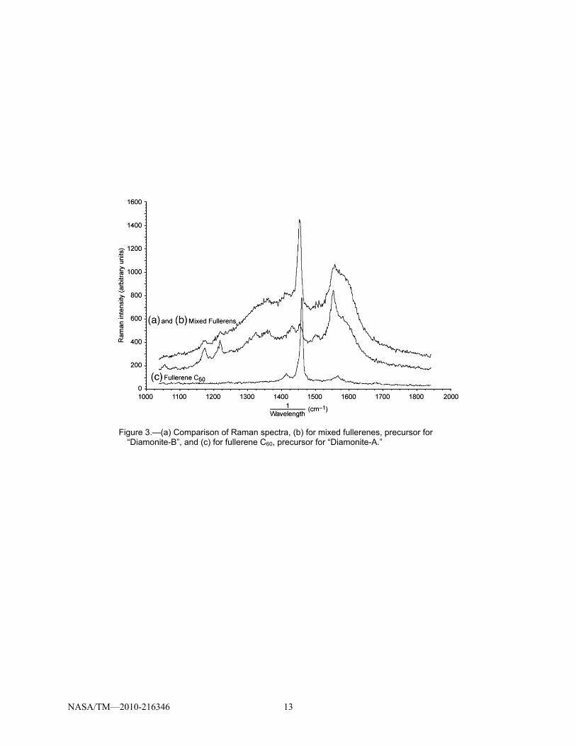
All of the Diatomite materials have typical carbon spectra in the Raman, therefore it is important to compare their spectra to those of the starting materials to see if residual starting materials are present. The Raman spectra of the precursor powders for Diamonite-A (Fig. 3(c)) and Diamonite-B (Figs. 3(a) and (b)) are quite different from each other and the spectra of their respective carbon materials. Acquisition of these spectra was performed with the minimum acquisition time as the spectra are a function of exposure time to the 514.5 nm laser beam. Even under these conditions, some damage may have occurred to the samples. The Raman spectrum of C60 has one major sharp and intense peak at 1460 cm–1 and two smaller intensity peaks at 1419 and 1572 cm–1. The main peak in the Raman spectrum of the mixed fullerenes is also sharp and intense at 1454 cm–1. Other possible peaks in the mixed fullerenes can be identified in the first order region at: 1172, 1217, 1322, 1356, 1429, 1454, 1500, 1554, 1600 cm–1, which are superimposed onto a broad halo extending throughout the 1100 to 1800 cm–1 range. These spectra are difficult to reproduce due to sample heterogeneity (see Figs. 3(a) and (b)) and varying degree of laser damage during spectral acquisition but it is quite clear that the spectral complexity mirrors that of the sample.
Vander Wal et al., have done extensive characterization for the sintering of amorphous carbon into well-ordered structure (Ref. 10). In those efforts, the in-plane crystallite dimension, La, was determined by the de-skeletonized High Resolution-Transmission Electron Microscope (HR-TEM) images of various stages of thermal graphitization of amorphous carbon. In those investigations, La was found to be approximately linearly related to the integrated band intensity ratio of the Raman G to D peaks (IG/ID). Using data from Vander Wal et al., it is straightforward to estimate La for the various forms of carbon materials in this work. For Diamonites-A and -B, La is estimated to be on the order of ~0.9 nm, while the value for the graphite material is estimated to be ~1.7 nm. It should be pointed out that these La dimensions are from surface measurements only.
The Raman spectra of C60 and high pressure-temperature polymerized materials derived from initial C60 have been discussed in the literature, for example in (Refs. 11 and 12) (initial C60) and (Refs. 12 to 15) (transformed C60). In the work cited in (Ref. 12) the Raman was measured using a Renishaw Raman Microscope in the region 3500 to 200 cm–1 (640 to 810 nm) at room temperature. The exciting radiation form a He-Ne laser (λex = 638 nm) was focused in a 20 μm spot; the laser power was kept at 22 mW. Pristine C60 exhibited ten Raman-active vibrations at 1572, 1469, 1425, 1249, 1099, 774, 709, 494, 431 and 273 cm–1. The measurement has shown substantial spatial inhomogeneity of the transformed material. Exceptionally strong differences in the Raman data were observed for the 500 °C pressure-treated specimen. We do not discuss the differences between these publications with our data since they used C60
powder synthesized in their laboratory. The technology of preparation varied in all investigations; therefore, we used commercial grade C60. The parameters of high pressure-temperature treatment in this effort were completely different, so some differences in the Raman spectra of initial and transformed C60 are not surprising. The data on Raman spectra and other properties of initial “mixed fullerenes” powder and Diamonite-B are not described in the literature and are first presented in this publication.

NASA/TM—2010-216346 6
3.2 Characterization by Electron Microscopy and X-ray Methods
The results of microscopic characterization, high-resolution TEM images and X-ray patterns were reported previously (Refs. 2 and 4). The results on precursor powders, mixed fullerenes and fullerene C60 are depicted in Figures 4 and 5. A HR-TEM was used to obtain crystallographic (lattice structure) information from electron diffraction; chemical composition was derived from energy dispersive x-ray analysis; chemical bond type from electron energy loss spectroscopy; and textural information from direct images. The same analysis is performed on the materials produced by HPHT processing.
Mixed fullerenes powder shows ordered zones of carbon atoms and amorphous disordered regions. Importantly, this precursor material for the synthesis of Diamonite-B densifies, compresses, compacts, and sinters. Although we do not know the exact chemical composition of this precursor material, we are confident that this kind of “soot” can be used in practical applications. Some forms of carbon black have been shown to compress, but do not compact or sinter like, for example, “activated carbon powder”, or may not densify, compress, compact or sinter at all like, for example, “glassy carbon powder”. “Carbon black” from acetylene compresses, but does not densify, compact or sinter while some graphitic powders densify, compress, and compact, but never sinter. Others densify, and compress, but don’t compact or sinter. All precursor powders for “Diamonites” can be sintered, including C60 (Fig. 5) which is the precursor for Diamonite-A.
Figure 5 shows a photomicrograph of fullerene C60 that have been extracted and refined into solid grains, often referred to as fullerite, which is held together by quadrupole electrical forces to form a molecular crystal. Fullerite is a soft, well-arranged and close-packed form of C60 (1.6 g/cm3) that has some defects in its arrangement. As can be seen, this type of powder has a very well ordered structure of carbon atoms and it is quite different from the structure of mixed fullerenes. The details on commercial manufacturing of fullerene-type carbon powders that were predicted, observed and synthesized by Osawa, Kroto, Smalley, Huffman, Kratschmer, and others during the 1970s to 1990s can be found in reference 16.
The results for the new carbon material, Diamonite-B, and a comparison with a sample of industrial graphite material are shown in Figures 6 and 7. Results shown in Figures 6(b) and (c) indicate that the microstructure of Diamonite-B is rather amorphous, the two peaks in the x-ray diffraction pattern are low intensity and very broad, contrary to graphite material peaks that are high intensity and sharp. High resolution TEM-images also show the existence of ordered crystallite structure in graphite and the absence of medium and long-range order in this new material. This observation is further supported by the Raman data (Fig. 1(a)) and leads to the conclusion that Diamonite-B consists of co-polymerized buckyballs, single-wall nanotubes and fragments of fullerene blocks inserted into the intermediate space yielding a dense, non-porous structure of carbon atoms with mixed sp2-sp3 hybridization and having a small La.
The synthetic graphite material (Fig. 7) is observed to have a well-arranged layered structure of carbon atoms with regions of order that are nano-sized and randomly oriented which is consistent with the La estimated from the Raman data. There are pores inside hexagonal layers and other defects. The X-ray diffraction pattern shows the high–intensity, sharp peaks associated with graphite as does the Raman spectrum in Figure 1(b).
3.3 Main Properties of the New Carbon Material, Diamonite-B, Compared With Synthetic Graphite and Diamond Materials
The samples of new carbon materials can be sintered using different processing parameters: pressure (P), temperature (T), hold time at P and T, and from different mixtures of fullerenes-nanotubes in the carbon black. Macroscopic properties of such samples will be different; therefore, the anticipated range of properties needs to be addressed. The same can be said about different grades of industrial graphite material where properties depend heavily on source material, technology and manufacturer. In this paper,

NASA/TM—2010-216346 7
we focus on defined values that can be measured with high precision. Table 2 lists the macroscopic properties of Diamonite-B sample, prepared as described in Section 2.1, which are compared to our sample of synthetic graphite and diamond materials. This table deals with experimentally-defined values rather than ranges of properties. The differences are obvious and conclusions drawn from them should make identifying practical applications of the new carbon material obvious.
From Table 2, the main differences are hardness and thermal conductivity. Graphite is extremely soft whereas Diamonite-B is harder than hardened steel. Graphite is a good thermal conductor, whereas Diamonite-B is an insulator. The high temperature properties are similar: thermal stability is the same, oxidation resistance in air is almost the same, although Diamonite-B oxidizes more slowly than graphite. The chemical stability, however, is quite different: graphite gradually dissolves in boiling perchloric acid, but Diamonite-B does not react, which is similar to the behavior of diamond. The color of Diamonite-B is similar to graphite, varying from gray to black. It should be noted that some references indicate the Mohs hardness of graphite is less than 1, and some graphite materials can be rated higher than 2. The hardness value presented in Table 2 is a result of our measurements on the particular sample that was synthesized and investigated specifically for this work. Hardness of soft carbon-based materials like graphite and polymers is usually determined with a Durometer on the Shore scale which is not applicable for hard materials. For hard materials, the micro hardness is determined on Vickers, Knoop, Brinell, Rockwell and other appropriate scales. For this reason we present the data on the Vickers scale for Diamonite-B and diamond material, and on the Shore scale for the graphite material.
3.3.1 Hardness Measurements
Measuring hardness on the Vickers scale is performed using a diamond indentor loaded by force, F. The tip of the indentor is shaped like a square pyramid, which leaves a surface indentation (cavity) of square cross-section, where “a” is the side of the square, and the indentation size is measured with an optical microscope. A Buehler’s Microhardness Tester (Micromet 2101) was used with loading force F = 25, 50, 100, 200, 300, 500, 1000 gf. The optical microscope with a Filar Micrometer Eyepiece allows the measurement of length (formally) with 0.1 m precision at x400 magnification. The hardness value may be expressed in SI units (Pa), using the following formula: HV (GPa) ~ 9.8 F / a2 (4) where F is in units of gf and a is in m.
This methodology was used to determine the hardness of many hardened steels, alloys, cermets and materials, as well as on etalon hardened steel (ASAHI 72553), a reference standard. The hardness values for the etalon steel lie in the 7.3 to 7.8 GPa range, Table 3.
Measuring the hardness of Diamonites is a more difficult task, since the indentor does not leave a clearly visible cavity on the Diamonite surface, but only a cross-like impression. The surface around the cross is flat, which indicates that deformation is mostly elastic in nature (Ref. 17); therefore, for Diamonite samples the indentation size is determined by the length of the pyramid diagonal.
Figure 8(a) shows indentations on an ASAHI 72553 etalon hardened steel as compared to those of Diamonite-B (Fig. 8(b)). Table 3 presents the corresponding hardness data. Samples of Diamonite-B sintered under P = 1 GPa pressure scratch any hardened steel, (HM 7, HV = 5-10 GPa). The hardness of Diamonite-B varies from HV = 11.5 to 21.3 GPa.
In conclusion, the interpretation of results for Raman scattering of light from the surface of the new bulk-carbon material, Diamonite-B, will be discussed in the terms of customary interpretations adopted for “amorphous carbon” in reference (Ref. 18). According to this terminology, diamond-like carbon is a metastable form of amorphous carbon with significant sp3 bonding. In contrast to Diamonite-B, this definition refers to carbon films deposited by chemical vapor deposition (CVD) of hydrocarbons or other deposition methods and frequently contains a certain amount of hydrogen which differs significantly from Diamonite-B. Historically, the definition of “amorphous” was applied to certain types of carbon black

NASA/TM—2010-216346 8
with very broad and weak peaks in the XRD patterns. Thermodynamic calculations performed for bulk pieces of graphite and diamond indicate that graphite is the stable form of carbon at P<1 GPa, and diamond is stable at P>10 GPa. In the 1 to 10 GPa range, the stable form depends on temperature thus forming the line of equal thermodynamic potentials for graphite and diamond and define the regions on the P-T carbon phase diagram where diamond and graphite are either stable or “metastable”. These results are valid only for “bulk” pure carbon materials where the volume energy of a solid piece is much larger than the surface energy. This is not the case for soot particles or thin films of carbon, where the surface energy may be equal to or even exceed the energy of atoms located inside the material body. Later, the quantum mechanical model of sp, sp2 and sp3 hybridization was developed to describe the multitude of carbon forms and organic compounds. Thermodynamic calculations can be performed for nano-particles, nano-films of pure carbon and hydrocarbons as well. Diamonite-B, a bulk-carbon material, has a distinct Raman spectrum and XRD pattern that differs from either diamond or graphite. TEM-images show that its carbon atoms do not exhibit long range order, and macroscopic properties differ from the properties of graphite and diamond. All data support the conclusion that it is a new type of bulk carbon. Bulk diamond and graphite are “crystalline” forms of carbon, but Diamonite-B can be characterized as an “amorphous” form of bulk carbon. Structural order causes very broad lines in Raman spectra. This can be explained by mixed sp2 and sp3, and probably also sp bonds.
4.0 Conclusions
Data from the Raman spectrum of the previously described new carbon material, Diamonite-B, shows that this material has a rather amorphous structure with short-range order. The D and G peaks in the Raman spectrum are very broad implying that the atoms are joined by chemical bonds that can be characterized by both types of hybridization of electron shells: sp2 and sp3 types. The amorphous structure is comprised of the remnants of the “buckyballs” and possibly “single-wall nanotubes” joined by covalent bonds. The TEM images, X-ray diffraction patterns and other microscopic data are consistent with this conclusion. The macroscopic properties of this new carbon material, such as density, hardness and the low value of thermal conductivity also point toward an amorphous structure with mixed hybridization.
References
1. J.R. Dennison, M. Holtz, G. Swain, Raman Spectroscopy of Carbon Materials, Spectroscopy 11 (1996) 38–43.
2. O.A. Voronov, G.S. Tompa, B.H. Kear, W.E. Mayo, S.C. Liao, R.K. Sadangi, K.J. Livi, R.O. Loutfy, High Pressure High Temperature Consolidation of Carbon Nanotubes for Structural and Other Applications, Report DMI-41023-FINAL for US Army Aviation & Missile Command, DoD DARPA, 1998.
3. O.A. Voronov, G.S. Tompa, Fullerene based sintered carbon materials, US Patent 6,783,745 B1, 2004.
4. O.A.Voronov, G.S. Tompa, B.H. Kear, High Pressure/High Temperature Consolidation of Fullerenes and Nanotubes for Precision Cutters and Other Applications, Report DMI-41035-REPFINAL for US Army Aviation & Missile Command, DoD DARPA, Contr.No.DAAH01-00-C-R008, (and K.J.T. Livi in Attachment K.3), 2003.
5. P.A. Cahill, Semiempirical study of hydrogen addition to single-walled carbon nanotubes, in: R.S. Ruoff, K.M. Kadish (Eds.), Fullerenes, Recent Advances in the Chemistry and Physics of Fullerenes and Related Materials, Proceedings Volume 95–10, The Electrochemical Society Inc., Pennington, NJ 08534-2896, 1995, pp. 1271–1275.
6. O.A. Voronov, High Pressure and High Temperature Apparatus, US Patent 6,942,729 B2, 2005. 7. G.S. Landsberg, L.I. Mandelstam, Eine neue Erscheinung bei der Lichtzerstreuung In Kristallen,
Naturwissenschaften, 16 (1928) 557 (in German). 8. C.V. Raman, K.S. Krishnan, A new type of secondary radiation, Nature, 121 (1928) 501.

NASA/TM—2010-216346 9
9. G.S. Landsberg, P.A. Bashulin, M.M. Suchinskiy, Main Parameters of Combined Scattering Spectra of Hydrocarbons, Nauka, Moscow, 1956 (in Russian).
10. R.L. Vander Wal, A.J. Tomasek, K.W. Street, W.K. Thompson, Carbon Nanostructure Examined by Lattice Fringe Analysis of High Resolution Transmission Electron Microscopy Images, Appl. Spectr. 58 (2004) 230–237.
11. D.S. Bethune, G. Meijer, W.C. Tang, H.J. Rosen, W.G. Golden, H. Seki, C. Brown, M.S. de Vries, Vibrational Raman and infrared spectra of chromatographically separated C60 and C70 Fullerene clusters, Chem. Phys. Letters 179 (1991) 181–186.
12. M.E. Kozlov, S. Kazaoui, N. Minami, K. Yakushi, M. Tokumoto, Spectroscopic investigation of high-pressure phases of C60 fullerene, in: R.S. Ruoff, K.M. Kadish (Eds.), Fullerenes, Recent Advances in the Chemistry and Physics of Fullerenes and Related Materials, Proceedings Volume 95–10, The Electrochemical Society Inc., Pennington, NJ 08534-2896, 1995, pp. 90–98.
13. Y. Iwasa, T. Arima, R.M. Fleming, T. Siegrist, O. Zhou, R.C. Haddon, L.J. Rothberg, K.B. Lyons, Jr., H.L. Carter, A.F. Hebard, R. Tycko, G. Dabbagh, J.J. Krajewski, G.A. Thomas, T. Yagi, New phases of C60 synthesized at high pressure, Science, 264 (1994) 1570–1572.
14. M.E. Kozlov, K. Yase, N. Minami, P. Fons, H.A. Durand, M. Hirabayashi, K. Nozaki, M. Tokumoto, H. Ihara, Study of the superhard form of carbon prepared from C60 fullerene, in: R.S. Ruoff, K.M. Kadish (Eds.), Fullerenes, Recent Advances in the Chemistry and Physics of Fullerenes and Related Materials, Proceedings Volume 95–10, The Electrochemical Society Inc., Pennington, NJ 08534-2896, 1995, pp. 99–107.
15. M.E. Kozlov, M. Hirabayashi, K. Nozaki, M. Tokumoto, H. Ihara, Transformation of C60 fullerenes into a superhard form of carbon at moderate pressure, Appl. Phys. Lett. 66 (1995) 1199–1201.
16. J.C. Withers, R.O. Loutfy, T.P. Lowe, Fullerene Commercial Vision, Fullerene Science and Technology 5 (1997) 1–31.
17. O.A. Voronov, G.S. Tompa, B.H. Kear, Lightweight Carbon Ceramic Composites for Thermally Resistant Bearings, Report DMI-41070-FINAL for USAF/AFMC, DoD MDA, Contr.No.F33615-03-M-5036, 2004.
18. J. Robertson, Diamond-like amorphous carbon, Mat. Sci. Eng. R37 (2002) 129–281.

NASA/TM—2010-216346 10
TABLE 1.—RAMAN SPECTRAL DATA FOR THREE CARBON MATERIALS: DIAMONITE-B, GRAPHITE MATERIAL AND DIAMOND MATERIAL, AND FOR CARBON BLACK PRECURSORS TO DIAMONITE-A AND DIAMONITE-B
Carbon material Peak region
Region range from 1/λ1 to 1/λ2
(cm–1)
Maximum 1/λij (cm–1)
Integrated band intensity (I) ratio
Remarks
New carbon ceramic (Diamonite-B)
1st order region
2nd order region
985 to 1800
2315 to 3338
(i,j)a (1,1) 1353 (1,2) 1576 (2,1) 2877
I12/I11 = 0.51
Broad Broad Exact peak location unidentifiable
Graphite ceramic 1st order region
2nd order region
985 to 1800
2315 to 3338
(1,1) 1345 (1,2) 1573 (2,1) 2455 (2,2) 2701 (2,3) 2942 (2,4) 3244
I12/I11 = 3.4
Narrow Narrow Narrow Narrow Narrow Narrow
Pyrolytic graphite (commercial grade)
1st order region
985 to 1800
(1,1) 1352 (1,2) 1579
I12/I11 = >11
Narrow Narrow
Diamond ceramicb Fluorescence
Raman
400 to 1800
985 to 1800
(fl) 1310 1338
Very broad Very narrow
Precursor for Diamonite-B (mixed fullerenes and nanotubes)
1st order region halo
985 to 1800 (1,1) 1172 (1,2) 1217 (1,3) 1322 (1,4) 1356 (1,5) 1429 (1,6) 1454 (1,7) 1500 (1,8) 1554 (1,9) 1600
All peaks are narrow and superimposed onto a very broad halo
Carbon ceramic (Diamonite-A)
1st order region
2nd order region
985 to 1800
2577 to 3115
(1,1) 1385 (1,2) 1577 (2,1) 2865
I12/I11 = 0.47
Broad Broad Broad
Precursor for Diamonite-A (fullerene C60)
1st order region
985 to 1800 (1,1) 1419 (1,2) 1460 (1,3) 1572
Narrow Narrow Narrow
aWhere “i” designates region and “j” designates peak number in that region. bRaman data acquired with 785 nm laser stimulation.

NASA/TM—2010-216346 11
TABLE 2.—MAIN MACROSCOPIC PROPERTIES OF NEW CARBON MATERIAL IN COMPARISON WITH GRAPHITE MATERIAL AND DIAMOND MATERIAL
AT AMBIENT PRESSURE AND TEMPERATURE Carbon Ceramic
Apparent density, g/cm3
Hardness on Mohs scale
Hardness on Vickers scale,
HV1, GPa
Hardness on ShoreD-scale
Resistivity, µohm·cm
Thermal conductivity
W/(m·K)
Thermal expansion, 10–6 K–1, (300 to
500 K range)
Diamonite-B Graphite Diamond
1.76
1.75
3.29
8.5
1.5
10
11.5
----
75
--
75
--
20600
1120
>10+12
2.1
116
400
2.8
3.8
1.0
aThermal expension is measured in 300 to 500 K range. bSamples of new carbon ceramic, Diamonite-B, graphite ceramic and diamond ceramic were fabricated as it was described in Section 2.1
TABLE 3.—VICKERS HARDNESS DATA FOR ETALON HARDENED STEEL (ASAHI 72553) AND DIAMONITE-B SINTERED AT P = 1 GPA
Vickers scale ASAHI 72553 Diamonite-B HV
a (GPa)
HVb
(GPa) HV
a (GPa)
HVb
(GPa) HV0.1 7.3 7.8 20.6 18.8 HV0.2 7.3 7.7 21.3 20.9 HV0.3 7.6 7.7 13.8 16.1 HV0.5 7.8 7.5 19.1 16.2 HV1 7.6 7.4 11.5 12.4
aBased on the measurement of the side dimension of the pyramid indent. bBased on the measurement of the diagonal dimension of the pyramid indent.

NASA/TM—2010-216346 12
Figure 1.—Raman spectra of (a) Diamonite-B derived from mixed fullerenes sintered under high pressure, (b) synthetic graphite material, and (c) commercial pyrolytic graphite.
Figure 2.—(a) Fluorescence and Raman spectra of diamond material sintered under very high pressure from synthetic diamond powder and (b) Raman spectrum smoothed and corrected for fluorescence background.
NASA/TM—2010-216346 13
Figure 3.—(a) Comparison of Raman spectra, (b) for mixed fullerenes, precursor for
“Diamonite-B”, and (c) for fullerene C60, precursor for “Diamonite-A.”

NASA/TM—2010-216346 14
Figure 4.—Characterization results for mixed fullerenes, precursor for “Diamonite-B” carbon material: (a) a photomicrograph (X30) of actual powder; (b) HR-TEM image; and (c) X-ray diffraction pattern from CuKα.

NASA/TM—2010-216346 15
Figure 5.—Characterization results for C60 precursor of Diamonite-A: (a) a microphotograph (X30) of actual powder, (b) HR-TEM image, and (c) X-ray diffraction pattern from CuKα.

NASA/TM—2010-216346 16
Figure 6.—(a) High resolution TEM micrograph: nanostructure of Diamonite-B, (b) electron diffraction pattern of Diamonite-B, (c) XRD pattern of Diamonite-B from CuKα, and (d) image of a specimen polished to mirror quality.

NASA/TM—2010-216346 17
Figure 7.—Characterization of synthetic graphite material: (a) high resolution image showing a mixture of graphite planes and (b) X-ray diffraction pattern from CuKα showing graphite peaks.

NASA/TM—2010-216346 18
Figure 8.—Photomicrographs of indentations for
Vickers hardness determination: (a) for etalon hardened steel (ASAHI 72533) and (b) for Diamonite-B (sintered at P =1 GPa).

REPORT DOCUMENTATION PAGE Form Approved
OMB No. 0704-0188 The public reporting burden for this collection of information is estimated to average 1 hour per response, including the time for reviewing instructions, searching existing data sources, gathering and maintaining the data needed, and completing and reviewing the collection of information. Send comments regarding this burden estimate or any other aspect of this collection of information, including suggestions for reducing this burden, to Department of Defense, Washington Headquarters Services, Directorate for Information Operations and Reports (0704-0188), 1215 Jefferson Davis Highway, Suite 1204, Arlington, VA 22202-4302. Respondents should be aware that notwithstanding any other provision of law, no person shall be subject to any penalty for failing to comply with a collection of information if it does not display a currently valid OMB control number. PLEASE DO NOT RETURN YOUR FORM TO THE ABOVE ADDRESS.
1. REPORT DATE (DD-MM-YYYY) 01-05-2010
2. REPORT TYPE Technical Memorandum
3. DATES COVERED (From - To)
4. TITLE AND SUBTITLE Raman Scattering in a New Carbon Material
5a. CONTRACT NUMBER
5b. GRANT NUMBER
5c. PROGRAM ELEMENT NUMBER
6. AUTHOR(S) Voronov, O., A.; Street, K., W., Jr.
5d. PROJECT NUMBER
5e. TASK NUMBER
5f. WORK UNIT NUMBER WBS 431731.04.01.03
7. PERFORMING ORGANIZATION NAME(S) AND ADDRESS(ES) National Aeronautics and Space Administration John H. Glenn Research Center at Lewis Field Cleveland, Ohio 44135-3191
8. PERFORMING ORGANIZATION REPORT NUMBER E-16821
9. SPONSORING/MONITORING AGENCY NAME(S) AND ADDRESS(ES) National Aeronautics and Space Administration Washington, DC 20546-0001
10. SPONSORING/MONITOR'S ACRONYM(S) NASA
11. SPONSORING/MONITORING REPORT NUMBER NASA/TM-2010-216346
12. DISTRIBUTION/AVAILABILITY STATEMENT Unclassified-Unlimited Subject Categories: 27 Available electronically at http://gltrs.grc.nasa.gov This publication is available from the NASA Center for AeroSpace Information, 443-757-5802
13. SUPPLEMENTARY NOTES Submitted to Diamond and Related Materials.
14. ABSTRACT Samples of a new carbon material, Diamonite-B, were fabricated under high pressure from a commercial carbon black--identified as mixed fullerenes. The new material is neither graphite-like nor diamond-like, but exhibits electrical properties close to graphite and mechanical properties close to diamond. The use of Raman spectroscopy to investigate the vibrational dynamics of this new carbon material and to provide structural characterization of its short-, medium- and long-range order is reported. We also provide the results of investigations of these samples by high-resolution electron microscopy and X-ray diffraction. Hardness, electrical conductivity, thermal conductivity and other properties of this new material are compared with synthetic graphite-like and diamond-like materials, two other phases of synthetic bulk carbon. 15. SUBJECT TERMS Carbon; Ceramics; Raman spectroscopy; Carbon material; Diamond; Vickers hardness
16. SECURITY CLASSIFICATION OF: 17. LIMITATION OF ABSTRACT UU
18. NUMBER OF PAGES
24
19a. NAME OF RESPONSIBLE PERSON STI Help Desk (email:[email protected])
a. REPORT U
b. ABSTRACT U
c. THIS PAGE U
19b. TELEPHONE NUMBER (include area code) 443-757-5802
Standard Form 298 (Rev. 8-98)Prescribed by ANSI Std. Z39-18