Embed Size (px)
Citation preview

RAJASTHAN ELECTRONICS & INSTRUMENTS LIMITED, JAIPUR
(An ISO 9001 : 2015& 14001 : 2015 “Mini Ratna” Central Public Sector Enterprise)
2, KANAKPURA INDUSTRIAL AREA, SIRSI ROAD,
JAIPUR-302034
Tel No: 0141- 2471083
E-mail: [email protected]. website: www.reiljp.com
NOTICE INVITING TENDER FOR“ Supply of BOS, Design, Engineering, Energy Supply, Installation,
Testing, Commissioning, Synchronizing with Evacuation at 11kv substation inside the premises
,comprehensive , Operation & Maintenance for 12 years of 200 kW Grid Connected Solar PV Plant in
Udaipur ,Rajasthan from regular/ approved vendors”
TENDER NO. . REIL/RE/19-20/PP/19135 dated 18.10.2019
Important Dates
Last Date & Time for submitting e- tender: 24/10/2019 up to 15:00
Date & Time for opening of e-tenders 25/10/2019 at 15:00
Kindly note that only online bid will be considered against this tender

RAJASTHAN ELECTRONICS & INSTRUMENTS LIMITED, JAIPUR
NOTICE INVITING TENDER NO. REIL/RE/19-20/PP/19135
This is a Notice Inviting Tender (NIT) for Supply of BOS, Design, Engineering, Energy Supply,
Installation, Testing, Commissioning, Synchronizing with Evacuation at 11 KV substation inside the
premises ,comprehensive , Operation & Maintenance for 12 years of 200 kW Grid Connected Solar PV
Plant at Titardi, Udaipur ,Rajasthan as per description and terms & conditions specified hereinafter:
Item Description:
S. No. Description
1. Supply of BOS, Design, Engineering, Energy Supply, Installation, Testing,
Commissioning, Synchronizing with Evacuation at 11kv substation inside the
premises ,comprehensive , Operation & Maintenance for 12 years of 200 kW
Grid Connected Solar PV Plant at Titardi, Udaipur ,Rajasthan.
1.2 E-Tendering Procedure: The work shall be carried out through submission of online tenders only.
No offer in physical form will be accepted and any such offer if received by REIL will be out rightly
rejected. Tender documents can be downloaded from our website www.reiljp.com or website of CPPP
www.eprocure.gov.in.Final bids are to be submitted on website www.eprocure.gov.in.Any changes
modification in the tender enquiry will be intimated through above websites only. Tenderer are
therefore, requested to visit our Website regularly to keep themselves updated.
The bidder should have a valid Digital Signature certificate issued by any of the valid certifying
Authorities to participate in the online tender.
The bids shall be uploaded in electronic form only through e-tendering system on website
www.eprocure.gov.in.
Note: e- Procurement system does not allow submission of documents after due date of tender.
Incomplete form or non-submission of documents to verify details may results into rejection of
your offer and no communication shall be done for submission of documents.
Only those contractors who are approved with REIL for required Installation and commissioning
work can quote against this tender.
Price Bid:-Price Bid format given with tender is to be uploaded after filling all relevant information
like basic prices, taxes & duties. The Price bid should be uploaded strictly as per the format available
with the tender failing which the offer is liable for rejection (remaining or changing format of price
sheet will not be accepted by system). REIL reserve the right to distribute the work.

Annexure-I
RAJASTHAN ELECTRONICS & INSTRUMENTS LIMITED, JAIPUR
Process Compliance Form
(Tenders are required to print on their company‟s letter head and signed, stamp before uploading).
To
Dy. General Manager (Proc.)
M/s Rajasthan Electronics & Instruments Limited
2, Kanakpura Industrial Area, Sirsi Road,
Jaipur-302034
Sub:- Acceptance to the process related Terms and Conditions for the e-Tendering
Dear Sir,
This has reference to the Terms & Conditions for e-Tendering mentioned in the tenderNo.:-
REIL/RE/19-20/PP/19135
We hereby confirm the following:-
1) The undersigned is authorized representative of the company.
2) We have carefully gone through the NIT, Tender Documents and the Rules governing the e-
tendering as well as this document.
3) We will honor the Bid submitted by us during the e-tendering.
4) We undertake that if any mistake occurs while submitting the bid from our side, we will honor the
same.
5) We are aware that if REIL has to carry out e-tender again due to our mistake, REIL has the right to
disqualify us for this tender.
6) We confirm that REIL shall not be liable & responsible in any manner whatsoever for my/our
failure to access & submit offer on the e-tendering site due to loss of internet connectivity,
electricity failure, virus attack problem with the PC, digital signature certificate or any other
unforeseen circumstances etc.
With regards
Signature with company seal
Name:
Designation:
E-mail Id:

Brief of Project :-
The 200kWp grid-connected ground mounted/rooftop solar PV projects on the land in cattle
hose premises. The generated solar power shall evacuate 11kv substation inside the premises
and power will feed directly to the grid. The scheme aims to reduce the fossil fuel based
electricity load on main grid.
The Bidder is advised to read carefully all instructions and conditions appearing in this
document and understand them fully. All information and documents required as per the bid
document must be furnished. Failure to provide the information and / or documents as required
may render the bid technically unacceptable.

Annexure - II
A) ELIGIBILITY CONDITIONS:
Bidder must fulfill following criteria:-
1. Experience in Installation & Commissioning of Cumulative 200 kWp SPV Power Packs.
2. Experience in Maintenance of cumulative 200 kWp SPV Power Packs.
3. Contractor must having valid electrical Contractor License issued by Electrical inspectorate
Department, Govt. of Rajasthan.
OR
1. Party having experience for Installation – Commissioning and fabrication of 200 kWp SPV
Power Plants.
2. Contractor must having valid electrical Contractor License issued by Electrical inspectorate
Department, Govt. of Rajasthan.
NOTE:-
1. Only those contractors who are registered with REIL for Installation &
Commissioning of Solar Systems can quote against this tender.
B) FINANCIAL CAPABILITY, EXPERINCE:-
1. Firm should have average turnover of Rs. 1 Cr. in last three financial years.
Bidder should submit following documents along with Technical bid on website:-
1. Bankers Report.
2. Balance sheet for last two years.
3. Turnover and Networth value duly certified by CA.
4. Photocopy of the last Three years Income Tax Return.
5. Experience in Installation, Commissioning and maintenance of SPV Power Plant
Systems. (attached verified documents such as I&C and maintenance certificate.
6. Photocopy of GST/service tax registration No., TIN no., PAN no.
7. Any other relevant documents
C) EARNEST MONEY & SECURITY DEPOSIT
1. The tender must be accompanied by a sum of Rs. 1,50,000/- (Rupee One Lakh Fifty
Thousand only) as Earnest Money in the form of deposit receipts, demand drafts or Bank
Guarantee failing which the tender shall be summarily rejected. These forms of earnest
money could be either of the Punjab National Bank or of any of the Nationalized Banks or
by a scheduled bank.
2. Bank Guarantee should be valid for a period 06 month from the date of bid submission.

3. The Successful Bidder shall deposit the Security deposit of amounting to Rs. 3,50,000 only
(Rupee Three Lakh Fifty Thousand only) in the form of Bank Guarantee/Demand Draft
within 7 days from date of issuing of LOA and valid upto three months from the last date of
O&M period. The PBG shall be established/issued from the the Punjab National Bank or
of any of the Nationalized Banks or by a scheduled bank.
4. In case if EMD is submitted in the form of BG, it may be considered as Security Deposit
and bidder have to extend the validity of BG upto three months from the last date of O&M
period.

D) OTHER CONDITIONS:
a) Responsibility for executing Contract: The contractor is to be entirely responsible for
the execution of the contract in all respects in accordance with the terms and conditions as
specified in the acceptance of tender.
b) The contractor shall not sublet transfer or assign the contract to any part there of without the written permission of the Dy. General Manager (Proc.). In the event of the contractor contravening this condition, Dy. General Manager(Proc.) be entitled to place the contract elsewhere on the contractors account at his risk and the contractor shall be liable for any loss or damage, which the Dy. General Manager(Proc.), may sustain in consequence or arising out of such replacing of the contract.
d) Document: The bidder should have a valid PAN / TAN /GST NO & other statutory
document as applicable and produce attested copies of such certificates along with the tender
papers in Technical Bid, failing which the tender is liable to be rejected. Check list be attached.
e) Right to accept / reject: REIL reserves the right to reject any or all tender without assigning any reason whatsoever. Also, the REIL authority reserve the right to award any or part or full contract to any successful agency at its discretion and this will be binding on the bidder.
f) e quantity of the SPV Systems shown in the tender can be increased or decreased to any extent depending upon the actual requirement.
g) Assistance to contractor: The contractor shall not be entitled for assistance
either, in the procurement of raw materials required for the fulfillment of the contract or in the securing of transport facilities.
E) Service Center :The contractor shall given undertaking for providing service center in Ajmer for period of 5 years with contact details of technical persons.
F) PRICES:
a. Prices are to be quoted in Indian Rupees.
b. Prices quoted in the Price/Financial Bid must be meaningful and measurable in the context.
c. The prices quoted must be per Watt Peak (Wp) shown in the BOQ.
d. Price must be quoted in original sheet of BOQ failing which the same is liable to be rejected
e. Offer shall be valid for 90 days from the date of bid opening
f. Work may be distributed on L1 prices.
Scope of Work (REIL Jaipur) :
The following material will be supplied for Roof Top Grid Connected SPV Power Plant by
REIL Jaipur:
S. No. Description of Work
1. 300-330Wp or higher SPV Modules with MC4 Connector
2. String Inverters with Data logger

Scope of Work for 200 kWp(Vendor):
The following material will be supplied for 350 kWpRoof Top Grid Connected SPV Power
Plant :
S. No. Description of item Rating Quantity
A. Module Mounting
Structures
200 kWp for Ground
mounted/shed Structures
As per requirement
B. AC/DC/HT cables
As per Technical Specification
mentioned in Tender
As per requirement
C. Junction Boxes As per Technical Specification
mentioned in Tender
As per requirement
D. AC/DC Distribution Box As per Technical Specification
mentioned in Tender
As per requirement
E. MCB/MCCB/ACB As per Technical Specification
mentioned in Tender
As per requirement
F. Transformer and
accessories
As per Technical Specification
mentioned in Tender
As per requirement
G. Earth electrode As per Technical Specification
mentioned in Tender
As per requirement
H. Control/Communication
cables
As per Technical Specification
mentioned in Tender
As per requirement
I. Lightning arrester As per Technical Specification
mentioned in Tender
As per requirement
J. Solar Meter &Energy
Meters
As per Technical Specification
mentioned in Tender
As per requirement
K. MIP Boxes As per Technical Specification
mentioned in Tender
As per requirement
L. Fire Fighting Equipments
(Fire extinguisher, Fire
bucket etc.)
As per Technical Specification
mentioned in Tender
As per requirement
M. MCCB/MCB with enclose
&with locking facility
As per Technical Specification
mentioned in Tender
As per requirement
N. Supervisory Control And
Data Acquisition
(Scada)/Plant Monitoring
As per Technical Specification
mentioned in Tender
As per requirement
O. Isolater As per Technical Specification
mentioned in Tender
As per requirement
P. MC4 Connector As per Technical Specification
mentioned in Tender
As per requirement
Q. Ring type Copper lug As per Technical Specification
mentioned in Tender
As per requirement
R. Ring type Copper lug As per Technical Specification
mentioned in Tender
As per requirement
S. Ring type Alu. lug As per Technical Specification
mentioned in Tender
As per requirement
T. Ferrule (Alphabetic &
Numeric)
As per Technical Specification
mentioned in Tender
As per requirement
U. PVC conduit pipe As per Technical Specification
mentioned in Tender
As per requirement
V. GI Cable tray As per Technical Specification
mentioned in Tender
As per requirement
W. Cable ties As per Technical Specification
mentioned in Tender
As per requirement

X. Cable Glands Single
compression heavy duty
(Make: Comet)
As per Technical Specification
mentioned in Tender
As per requirement
Y. Sign boards for arrays,
PCU, control room, Caution
sticker (format attached)
etc
As per Technical Specification
mentioned in Tender
As per requirement
Z. Hot dipped GI strip As per Technical Specification
mentioned in Tender
As per requirement
AA. Sanitary fitting for Module
Cleaning arrangement with
pressure Motor pump
As per Technical Specification
mentioned in Tender
As per requirement
BB. Rubber Pipe flexible As per Technical Specification
mentioned in Tender
As per requirement
CC. Installation accessories
ladders, safety belts/shoes
etc required for safe I&C of
Power plants
As per Technical Specification
mentioned in Tender
As per requirement
DD. Any other
item/material/services for
completion of the particular
job as well as
commissioning of Power
Plant
As per Technical Specification
mentioned in Tender
As per requirement
EE. Other Equipments
mentioned in Technical
Specification
As per Technical Specification
mentioned in Tender
As per requirement
NOTE:-It is advised to contractor to prior visit of site before submission offer.
The scope of work of contractor for the project is as under:
Safety and security of the Materials at Site.
Material required such as cables glands, tags, cable trays, GI Strip for earthing material & item
mention in above list or in Technical specifications etc. to complete job.
Installation & commissioning of SPV Modules, String Inverter,
Supply, Installation & commissioning of Solar Meter, Energy meters, Accessories etc.
Supply,Installation of earthing material and lightning system, testing and commissioning of
complete earthing and lightning system as per specification requirement.
Laying, Termination, Glanding, Ferruling of all interconnecting cables among sub array, String
Inverter, Conduting, Cable Trays and load panel etc .
Wiring of complete solar system as per requirement.
Testing of DC/AC wiring as per requirement.
The scope of work of the contractor is to complete the Supply of BOS, I&C of SPV Power
Plant.
REIL shall handover all material at Site (SPV Modules & String Inverter only).
Any other work tools & tackle required for completion of the project shall be arranged by
the contractor.
Meter testing, CT testing in Discom Lab and liasioning with Discoms in the scope of contractor
All necessary items/manpower/arrangements required for Proper and Safe Installation &
Commissioning of Power Plant will be arranged by the agency/Contractor. Any material/item

other then mentioned in Scope of work (REIL) which is required for I&C of Power Plants is in
scope of the agency.
Contractor shall take all necessary steps, follow up &liasoning towards the Net Metering
arrangements .
Contractor will take necessary statutory approvals/ clearances from all concern departments ,
Electrical Clearance from department etc. for installation & commissioning of Power Plant.
Contractor shall re arrange the existing AC wiring if required.
All arrangements for their deployed workman/manpower at site will be take care by the agency.
Contractor/agency shall give declaration that site has been visited and all information towards
timely completion of project has been collected and taken care before quoting for the above
enquiry.
Prices quoted must be firm and fixed. No price variation/escalation shall be allowed.
Contractor shall arrange all the manpower and material required for inter-connection of the SPV
Power Plant to the load.
Contractor shall carry out the AMC of Power Plant for 12 years as per work order terms and
conditions.
After successful installation – commissioning of the Power Plant Contractor shall get a
certificate of installation, commissioning and satisfactory operation from beneficiary as per
requirement of work order. The scope of work also includes verification of documents from the
customer.
After installation – commissioning of the Power Plant Contractor shall arrange the inspection of
Power Plant from customer/ designated agency/REIL as per work order requirement and
expanses, if any, shall be borne by contractor.
Contractor shall install and commission the Power Plant in the stipulated time given by the
agency.
The payment of contractor shall be released after release of payment from agency.
Contractor will submit weekly Project Execution Plan (PEP) along with offer. In which
contractor gives the details that how will project accomplished. Contractor shall be also submit
the PERT CPM for project scheduling & Management.
Item no.1 of Schedule of Quantities: The brief scope of work included in this item is as given below.
Survey, Design, detailed Engineering, Supply (without SPV Modules & Inverters) , installation
testing and commissioning of 200 KWp Solar Photo Voltaic Power Plant including supply and
installation of the solar modules & arrays with associated system comprising of DC system,
cables & JBs, inverters, step up transformer of required rating for necessary connection to the
11 kv power station inside the premises at suitable voltage level, switchgears along with
adequate protection and monitoring facilities up to the grid connection point. all works required
for commissioning of 200KWp Solar Photo Voltaic Power Plant are included in the scope).
Conducting complete Glare analysis
Providing of suitable mounting structure including Civil foundations for PV arrays as per the
site conditions, to meet the wind speed conditions up to 200Km/Hr.
Submission & obtaining the approval of Electrical schematic of installation as well as power
evacuation scheme for the approval of statutory authorities as per the local laws at the
conceptual level and at commissioning level.
Integrated microprocessor-based SCADA with required software & hardware for control &
monitoring of SPV plant as per the best standards system
Provision of external lighting.
Earthing and lightning protection system for the whole plant.
Providing telephone / communication cables.
Providing Fire detection system and Fire fighting equipment.
Construction of RCC/PEB substation for Solar Plant.

Providing water supply including piping for distribution of water to various parts of plant.
Providing proper drainage system.
Providing internal paths required for maintenance of PV Panels
Item no.2 to 7 of Schedule of Quantities: Supply and laying of HT cables from Solar Power plant to
load center. Exact Measurement to be done by bidder during Survey and site visit.
Item no.8 to 9 of Schedule of Quantities:
Operation & Maintenance for a period of TWELVE Years (Including Initial 5Years under DLP)
& All-inclusive comprehensive maintenance contract after DLP
All other scope work as detailed in the technical specifications of the work and as mentioned in
the schedule of quantities. DRAWINGS ANDDOCUMENTS

TECHNICAL SEPCIFICATION OF EQUIPMENTS
I. Design, Detailed Engineering, Supply of BOS (except SPV Modules, Inverters) , transportation,
loading/unloading, storage, installation and commissioning of 200 kWp Capacity Solar PV Power
Plant and interconnecting to 11KV/440 V cattle house Sub-Station as required.
II. Design, Engineering of the solar modules & arrays with associated system comprising of DC
system, cables & Junction Boxes, inverters, transformation to the required voltage for necessary
connection to the grid at specified voltage level at the specified location, switchgears along with
adequate protection and monitoring facilities up to the grid connection point. Augmentation of the
Bus, to be carried out at the grid connection point at 11KV/440V, cattle house Indoor substation.
III. Optimum design, Engineering & providing of suitable mounting structure including Civil
foundations for PV arrays & layout etc. as required for mounting the modules as per the site
condition to meet the wind speed conditions up to 200Km/Hr. with anti-corrosion feature so as to
have minimum maintenance requirements during operational years of the plant.
IV. Before start of the work, the successful bidder is required to conduct its own detailed survey of
the site and submit a copy of the same to REIL. same to be incorporated in the detailed design.
V. Survey & route finalization of the transmission Cable(s) for connection to the nearby substation
feeder of 11KV/440V cattle house premises Sub- Station for power evacuation and injection.
VI. Erection/installation, of the solar PV plant along with associated system including power
transmission cable(s) and its termination(s) at the grid point etc as required.
VII. Submission & obtaining the approval of electrical schematic of installation as well as power
evacuation scheme for the approval of statutory authorities, AVVNL and Central Electricity
Authority as per the local laws at the conceptual level and at commissioning level.
VIII. Integrated Micro-Processor based SCADA with required software & hardware for control &
monitoring of SPV plant as per the best standards complete as required.
IX. All associated electrical works required for interfacing at 11 KV line as required based on site
conditions for optimal system design and usage (i.e., main step up transformer, breakers, LA, HT
switchgears, protection systems, cables, metering, earthing of required ratings based on the design
conditions etc.).
X. For Power supply and control voltage required during the start-up and pre- commissioning
suitable size underground cables shall be laid from the nearest source to the Inverter.
XI. Design, supply, laying, testing & commissioning of 11 KV Earthed line cabling & associated
equipment for connecting into 11KV/440 V Indoor Substation as per the technical specifications
XII. Provision of required size GI/HDPE pipes for laying of AC & DC Cables in solar farmyard for
crossing internal roads, without any extra cost.
XIII. Complete cleaning of existing cable duct, removal of debris, drain out of seepage & drainage
water etc., including lying of HT Cables, Communication cables and control cables through the
existing covered cable duct etc. complete as required.
XIV. Submission of Layout drawings for RCC / Pre Fabrication Structure(s) at for housing Inverter, HT
VCBs, LT Panels, Power Transformer, UPS etc., at one of the location in the enclosed drawing.
Complete design details of the infrastructure shall also be submitted.
XV. Provision of Standby power auxiliary power supply from premises Power Distribution nearby.
XVI. Earthing and advanced lightning protection system for the whole plant as per the local statutory
requirements.
XVII. Provision of power and water supply during construction phase including security etc. as required
for the installations till it is handed over to beneficiary.

XVIII. Providing Fire detection system and Fire fighting equipment.
XIX. Construction of RCC/PEB substation building for Solar Plant.
XX. Providing water supply including piping for distribution of water to various parts of plant.
XXI. Provision of Weather Monitoring System and Module Cleaning System.
XXII. The Complete Solar Power PV System shall be under Comprehensive Maintenance Contract
(CMC) and Operation & Maintenance for a period of TWELVE Years (Including Initial 5 Years
under DLP)
A. PLANNING AND DESIGNING:
I. The bidders shall provide complete design, detailed drawings, basis for selection of equipment
for all Electro-Mechanical works and shall be got approved from REIL before commencement
of installation work.
II. The bidders shall select suitable rating and capacities of the various equipment required for HT
power evacuation & injection in to the existing 11 KV system. The bidders shall ensure that
Power Evacuation & injection system is meeting the plant design & system requirements,
statutory requirements and AVVNL requirements.
III. The Contractor shall furnish the following drawings & documents on award of the work within
7 days and obtain approval from REIL.
IV. BAR/Activity Chart for the complete project in MS Project indicating various activities of
project such as time required planning, approval of drawings, fabrication of materials, factory
inspection, transportation, installation, testing and commissioning, obtaining statutory approvals
etc. complete as required. The time for the complete project shall be as indicated in the tender.
This BAR/Activity Chart to be submitted to REIL for approval within ten days on award of the
work and shall be the binding document for control and monitoring the progress of the project.
V. General arrangement and dimensioned layout of complete Solar PV System.
VI. Schematic drawing showing the SPV panel, inverter(s), Junction Boxes, AC and DC
Distribution Boards, meters etc.
VII. Detailed cable route drawings, selection of cable sizes, equipment‟s, General arrangement,
power and control drawings for all LT & HT equipment‟s, invertors, UPS, transformer etc.
VIII. Complete earthing layout, lightning protection and external lighting.
IX. Structural drawing along with foundation details for the RCC / pre- fabricated structures and
transformer foundations etc.
X. Itemized bill of material for complete SV plant covering all the components and associated
accessories.
XI. Layout of solar Power Array, Internal roads layout drawing.
XII. Water piping arrangement drawings for module cleaning. The drawing(s) should include the
pipe layout drawing and P & I drawing, with the sizes of various pipe section along with valve
locations etc. Also the successful bidder to inform the quantity and quality of water
requirements for module cleaning.
XIII. The bidder should carry out Shadow Analysis at the site and accordingly design strings & arrays
layout considering optimal usage of space, material and labour. The bidder should submit the
array layout drawings along with Shadow Analysis Report to REIL for approval on award of
work within 07 Days.
XIV. REIL reserves the right to modify the Layout and specification of sub-systems and components
at any stage as per local site conditions/requirements.

XV. The bidder shall submit preliminary drawing for approval & based on any modification or
recommendation, if any. The bidder shall submit three sets and soft copy in CD of final drawing
for formal approval to proceed with construction work.
B. ENERGY YIELD ESTIMATION & BENCH MARK FOR ENERGY YIELD COMPUTATION
Considering the site conditions, irradiance and ambient temperature, the Contractor shall calculate the
energy generation from the specified plant throughout the year, year on year for 25 years with the
annual average performance ratio and submit the same along with the bidder‟s technical bid.
Energy yield prediction essentially depends on simulations and loss assumptions. However, loss
benchmarks presented in the table below is considered for computation, Loss Description.
Soiling Bidders are advised to evaluate the dust profile on site and define the O&M strategy for
maintaining the soiling loss to 2%
Module Quality The bidders should select PV modules with positive tolerance only.
DC Cable losses Max 1.5%
AC Cable losses Max 1.5%
Grid availability 100% availability to be considered for simulation
Solar PV System(Plant)
A Grid Tied Solar Roof Mounted Photo Voltaic (SPV) power Source (Plant) shall consists of SPV
array, Module Mounting Structure, String Inverter consisting of Maximum Power Point Tracker
(MPPT), Inverter, and Controls & Protections, interconnect cables and switches. PV Array is mounted
on a suitable structure. Components and parts used in the SPV power plants including the PV modules,
metallic structures, cables, junction boxes, switches, inverters etc., should conform to the latest BIS or
IEC or international specifications, wherever such specifications are available and applicable. SPV
Modules and Inverters are supplied by REIL.
Following items shall provide by bidder (but not limited to them);
i. Mounting structures.
ii. DC Cables & Accessories, Junction Boxes
iii. String Monitoring Unit (Monitoring for each string)
iv. SCADA and Weather Monitoring Station
v. Step up transformer
vi. LT Cables and accessories as per site requirements and design.
vii. HT & LT Panels with protections.
viii. 11 KV UG Cabling from Solar Plant to 11KV/440 V cattle house Sub-Station
ix. Power Evacuation arrangement at 11KV/440 V cattle house Sub-Station
x. Earthing and lightning protections for the complete plant
xi. IR/UV protected PVC Cables, pipes and accessories and providing HDPE pipes for
laying of HT Cables, communication cables and control cables.
xii. UPS Power Supply System
xiii. External Electrification by LED fixtures

Any other item(s) or work, which is not specifically mentioned but essentially required for completion
& Successful Commissioning of the System.
C. PARTICULAR SPECIFICATIONS
I. ARRAY STRUCTURE
a) Hot dip galvanized MS / Aluminum mounting structures to be used for mounting the modules/
panels/arrays. Each structure should have angle of inclination as per the site conditions to take maximum
insulation. However, to accommodate more capacity the angle inclination may be reduced until the plant
meets the specified performance ratio requirements.
b) The Mounting structure shall be so designed to withstand the speed for the wind zone of the location
where a PV system is proposed to be installed (wind speed of 200 kM/ hour). It may be ensured that the
design has been certified by a recognized & reputed engineering college / Institution in this regard and
submit wind loading calculation sheet to REIL. Suitable fastening arrangement such as grouting and
calming should be provided to secure the installation against the specific wind speed. The mounting
structure and foundation etc. shall withstand design wind speeds as per IS 875 and meeting the local
requirements.
c) The mounting structure steel shall be as per latest IS 2062: 1992 and galvanization of the mounting
structure shall be in compliance of latest IS4759. Minimum thickness of galvanization for hot dip
galvanized sections is 120 Microns.
d) Minimum height to be maintained at the lower level of the module shall be 600mm. The entire structure
including the array shall be earthed to two independent earth electrodes and all earth electrodes shall be
interconnected.
e) Structural material shall be corrosion resistant and electrolytically compatible with the materials used in
the module frame, its fasteners, and nuts and bolts. Aluminum structures also can be used which can
withstand the wind speed of respective wind zone. Necessary protection, towards rusting need to be
provided either by coating oranodization.
f) All fasteners used in the structure and module mounting shall be made of SS 304 grade and shall meet
appropriate standards. The array structure shall be designed in such a way that it occupies minimum
space without sacrificing the output from SPV panels. As already specified, the bidder has to conduct his
own anti-glare analysis and the designs should consider and incorporate the recommendations of this
analysis by providing any modifications needed consequent to the antiglare analysis, without any extra
cost.
g) The structure shall be designed for easy replacement of any module considering either three modules in
the horizontal position or two modules in the vertical position. Depending on the roof condition for
blocks/module area, Module tables shall be designed in an aesthetical manner and in the same line/level.
the panel at regular intervals, easy maintenance and easy washing of the panels etc. as required.
h) The height of the array structure for mounting the PV modules and accessories shall not be more than
the permissible height for the respective locations as per the details given at Para1.

II. JUNCTION BOXES (JBs) /STRING MONITORING UNIT/STRING COMBINERBOX
a) String monitoring unit shall be provided for each string. Each string should have DC fuse/DC MCB, the
rating of which shall be as specified by the module manufacturer in the data sheet. The junction boxes
shall be dust, vermin and waterproof. It shall be made of thermo plastic/poly carbonate, sunlight/UV
resistive, and fire retardant having minimum IP 65 rating. It should have provision for cross ventilation
through vent plugs and suitable for structure mounting. The junction boxes shall have provision for
connecting earth wire for protection as per requirements.
b) The junction boxes shall have suitable cable entries fitted with cable glands of appropriate sizes for both
incoming and outgoing cables. Suitable markings shall be provided for easy identification and cable
ferrules shall be fitted at the cable termination points for identification. Junction boxes shall also have
suitable surge protection/arresting devices. The arrangement in the junction box shall conform to IEC
60364-7-712. A Main DC isolation switch of adequate rating shall be provided for disconnection
ofarrays/strings.
c) Copper bus bars/terminal blocks housed in the junction box with suitable termination threads
Conforming to IP65 standard and IEC 62208. Hinged door with EPDM/Poly urethane rubber gasket to
prevent water & dust entry to be provided with single compression cable glands and provision of
earthings. It should be placed at 5 feet height or above for ease of accessibility and maintenance.
d) Each Junction Box shall have High quality of suitable capacity Metal Oxide Varistors (MOVs) / surge
arrestors and suitable Reverse Blocking Diodes. The Junction Boxes shall have suitable arrangement
monitoring and disconnection for each of the groups. After disconnection, it should allow string voltages
to be measured separately.
e) Each junction shall have MODBUS RS 485 communication interface for monitoring as per IEC 61326-
1-2005 and the input current, system voltage and internal temperature to be monitored as a minimum,
and other parameter as specified in SCADA.
f) Suitable markings shall be provided on the bus bar for easy identification and the cable ferrules must be
fitted at the cable termination points for identification.
g) All the cables (Power, control and communication) from PV modules to junction box to be provided in
GI Pipe of suitable size, neatly fixed to the structure with SS Clamps and SS nuts and bolts, so that the
cables are not damaged by rats and rodent. Alternatively, the GI Pipes of suitable size may also be used
and which may be fixed neatly fixed on to the structure with SS clamps and SS nuts and bolts.
h) All the junction boxes shall be suitably identified and provided with engraved plates for easy
identification during maintenance.
III. DC & AC DISTRIBUTIONBOARDS:
The DC and AC Distribution boards shall be provided where ever required as per scope of work, design
requirements and site conditions. The distribution boards shall confirm to the following specifications
and requirements;
a) DC Distribution panel shall receive the DC output from the array field.
b) AC Distribution boards shall be provided wherever required. AC Distribution Panel Board
(DPB) shall control the AC power from String inverter and should have necessary surge
arrestors. Interconnection from ACDB to LT side of Step Up transformer for HT power
evacuation shall be made through suitable size Aluminum or copper armored cables as
required.

c) The distribution boards/panels shall be designed for minimum expected ambient temperature of
50 degree Celsius, 90% humidity and dusty weather.
d) All indoor panels will have protection of IP54 or better. All outdoor panels will have protection
of IP65 or better. The distribution boards should conform to Indian Electricity Act and rules (till
last amendment).
e) The AC Distribution boards/Panel shall be suitable for operation on a 415- Volt, 3 phases, 4
wire, 50 Hz. Earthed neutral supply, and capable of withstanding a symmetrical fault condition
of not less than 65 kA for 1second. All the 415 AC or 230 volts devices / equipment like bus
support insulators, circuit breakers etc., mounted inside the switchgear shall be suitable for
continuous operation and satisfactory performance under the following supply conditions
i. Variation in supply voltage + or -10%
ii. Variation in supply frequency + or -3Hz
f)
g) The MCBs, MCCBs, ACBs and other panel accessories shall meet the following specifications
and requirements. MCBs shall be used up to 16 Amp; MCCBs up to 400 Amp and above ACBs
shall be provided. However, for isolation, control and protection of Invertors (Centralized) only
ACBs shall be provided. The fault level shall be as specified and as per the site requirements.
IV. MINIATURE CIRCUIT BREAKER(MCB)
1. The miniature circuit breakers shall conform to IS8828-1996.
2. The miniature circuit breakers shall be single pole/double pole/triple pole/four pole as per site
requirement & required duty applications or AC or DC type. The breaking capacity of MCBs
shall have minimum 10 kA. The tripping characteristics shall meet the requirements of the duty
applications.
3. The MCB shall be of plug in type, trip reset facility and a common trip bar on TP/FPMCBs.
4. MCBs shall be with Trip free mechanism & toggle with positive contact indication.
5. The MCB shall have self-wiring contacts with full size silver tungsten alloy contracts.
6. Indications ON/OFF shall be molded into MCB.
7. Electrical endurance of the MCB shall be not less than 20,000 operations.
8. MCB used for controlling power circuits shall be with tripping characteristics of „C‟ curve
where as MCBs used to protect control transformer circuits shall be with tripping characteristic
of „D‟curve.
V. MOULDED CASE CIRCUIT BREAKER(MCCB):
i. The MCCB shall be suitable for inverter duty applications
ii. The MCCBs shall comply with IS: 13947 Part-II
iii. The thermal rating of circuit breaker shall be as specified in BOQ.
iv. Rated symmetrical breaking capacity ICS = ICU = ICS at 415 volt, 50HZ shall be as required
and not less than50KA
v. Rated insulation voltage shall be 750 volt AC50HZ.
vi. Rated operational voltage shall be 415 volt AC 50HZ.
Construction
vii. The MCCB should current limiting type with trip time less than 10msec under short circuit
conditions. The operating mechanism shall be quick make quick break type.

viii. The trip unit shall be thermal magnetic type up to 200A and Microprocessor based for rating
above 200 Amp. Thermal magnetic release should provide adjustable settings for O/L and Short
circuit. Microprocessor based release should have adjustable settings for Over Load, Short
Circuit and Earth Fault Protections.
ix. All MCCBs shall be equipped with front operated rotary handles. Outgoing from each of the
MCCB shall be extended to the cable alley by providing necessary busbar of suitable rating and
supports etc. for terminating the outgoing feeders.
x. The MCCB should be provided spreader links and phase barriers
Operation
xi. Push to trip facility shall be provided on the panel door.
VI. AIR CIRCUIT BREAKER(ACB)
General
i. The ACBs shall be suitable for inverter duty applications or as per the design requirements.
ii. The circuit breakers shall comply with IS :13947 Part –II.
iii. The thermal rating of ACBS shall be as required based on the design.
iv. Rated symmetrical breaking capacity, ICS = ICU = ICW for 1 sec at 415 volt, 50HZ shall be not
less than65KARated making capacity (peak) shall be minimum100KA
v. Rated insulation voltage shall be minimum 1000V AC,50HZ.
vi. Rated operational voltage shall be 415 volt AC, 50HZ.
Construction
vii. The air circuit breakers shall be electrically operated microprocessor based draw out type and
four pole version of rating as per requirement and site conditions and SLD.
Operating mechanism
viii. The operating mechanism shall be stored energy spring type with minimum closing time and
with Electrical chargedspring.
ix. Draw out mechanism with safety requirements
x. Positions in draw-out breakers. (Service + Test + Isolated +Maintenance)
xi. Safety shutters shall beprovided
xii. Door interlock shall beprovided
xiii. Locking in isolated position shall beprovided.
xiv. Mechanical indicators: The following mechanical indicators to be provided
xv. Main contacts closed „ON‟.
xvi. Main contacts open„OFF‟. Springcharged.
xvii. Spring discharged.
xviii. Circuit breaker in “Service”position.
xix. Circuit breaker in “Test” position.
xx. Circuit breaker in “Isolated” position.
xxi. Circuit breaker in “maintenance” position.

Characteristic of release
xxii. Microprocessor based release shall have following inbuilt protections:
xxiii. Over current release shall have a minimum range of 0.5 to 1.0 times adjustment.
xxiv. Earth fault release shall have minimum range of 0.2 to 0.5times adjustment.
xxv. Short circuit shall have minimum range of 2 to 8 times adjustment.
Communication and display
xxvi. Release should have inbuilt RS 485 communication port for SCADA connectivity and breaker
control through PC
xxvii. The release should have current display.
xxviii. The release should be provided with Zone Selective Interlocking
xxix. feature to achieve intelligent discrimination between ACBs and to reduce thermal and dynamic
stresses on the ystem
VII. INSTRUMENTATION
Digital meter shall be suitable for panel board mounting. Scale range shall meet with the requirements.
In the case of CT operated ammeters class of accuracy of CTs and protective class shall be as per the
design requirements. CTs used in the work shall be resin cast bar primary or wound primary as the case
may be and shall be in conformity with IS:2705- 1992 or IEC 185-1987. The short time rating of the CT
shall be 100 KA for one second. The burden of the CT shall be suitable for the application.
VIII. THERMAL OVER LOADRELAY
Thermal Overload Relay used in the circuit with contactor shall be in conformity with IS: 3842 part 2-
1966 and it shall withstand insulation test to IS: 12083 part 2. The relay shall be provided with
adjustable current settings and with a provision of sealing the same to make it tamper proof.
The relay shall have built in single phasing protection and over load protection as per IEC947- part 4.
The relay shall have in built NO & NC contact.
The thermal over load relay shall be suitable for Copper / Aluminum termination, with a maximum
permissible temperature rise of 65°C, at the terminals, with maximum ambient temperature of 50°C.
IX. INDICATION LAMPS
The indication lamps used in the work shall be LED Type with protection against electromagnetic
interference and over voltage. The lamps shall be suitable for operation on 240 Volts. Ingress protection
class of the lamp unit shall be IP: 65. The indication lamp unit shall be in conformity with IEC: 947 part
5 Section 1. The diameter of the lamp shall be not more than 22mm.
X. PUSH - BUTTONS
The push buttons shall be in conformity with IEC: 947 part- 5- Section 1 suitable for manual operation.
The ingress protection class of the unit shall be IP 65.

The push button units shall be suitable for operation on 240Volts and the contacts shall be rated for 3 - 5
amps on 240 volts. The color of push buttons shall be as follows:
a. Start PB -Green
b. Stop PB -Red
c. TestPB -Black
Reset PB –Yellow The successful bidder before fabrication of the distribution boards / Panel Boards
shall submit the general arrangement, Schematic, power and control wiring drawings for the approval of
REIL meeting the above specifications/requirements clearly indicating the selection criteria for the
MCBs/MCCBs/ACBs and bus bar sizes etc.
In case, the DC distribution boards are to be mounted on the array structure, then the array structures
shall be designed to meet the mounting load requirements and suitable mounting arrangements to be
provided. Only SS mounting arrangements with accessories shall b used.
All switch boards and panel boards before commissioning shall be tested with 1000 V insulation tester
and the insulation value between the live conductors and frame (ground) should not be less than 20
mega ohms. High voltage test shall be conducted at the factory where the panel boards remanufactured.
XI. INTEGRATION OF PV POWER WITHGRID:
The output power from SPV would be fed to the inverters, which converts DC produced by SPV array to
AC and feeds it into the main electricity grid after synchronization & step up to the required voltage. In
case of grid failure, or low or high voltage, solar PV system shall be out of synchronization and shall be
disconnected from the grid and shall automatically synchronize after grid restoration.
XII. UPS ANDBATTERY
An online UPS of required capacity for providing auxiliary supply to Inverters, with a backup of 30
Minutes minimum shall be supplied for each inverter room. Separate UPS of specified capacity with
battery backup of minimum 30 Minutes shall be provided for catering to the SCADA system. The
system should have the following minimum requirements. The UPS and Battery shall be of approved
make given in the tender and shall confirm to the relevant IS/BS/IEC specifications with up to date
amendments.
a) VRLA Battery with suitable rack
b) Built-in Isolation Transformer
c) UPS load power factor shall be 0.8 ormore
d) Output frequency – 50 Hz, True Sinewave
e) Overall efficiency -85% ormore
f) Input supply 1ph, 230 Volts ± 10%
g) Output Supply power 230V ±1%

XIII. TRANSFORMER
DRY TYPE DISTRIBUTION TRANSFORMERS (SOLAR CONVERTER DUTY)
General Construction
The Transformers shall comply with the following Indian Standards as amended upto date:
(i) IS 11171 : 1985 - Dry type power transformers.
(ii) IS 10028 (Part II & III) - Installation and Maintenance of Transformers.
(iii) IS 2099 - Bushing
(iv) IS 2705 - Current
Transformers. Constructional Features
All the MS parts shall be either Hot dipped galvanized or cold galvanized to make them corrosion free.
The core shall be made up of high grade low loss cold rolled grain oriented silicon steel. Both low &
high voltage windings shall be made of copper conductor. The class of winding insulation shall
correspond to class „F‟. The construction of the windings of the transformer shall be such that no
creepage path is found even in dusty & corrosive ambient conditions. The core coil assembly shall be
housed in a prefabricated enclosure. The enclosure shall be fabricated with mild steel CRCA sheets with
adequate provision for ventilation. The enclosures shall under go the seven tank process. Finally the
external and internal surfaces of the enclosure shall be powder coated with the required paint shade.
General Requirements
The transformer shall be indoor or outdoor type as specified. Unless otherwise specified the transformer
in addition shall have thermal and dynamic ability to withstand external short-circuit as per clause 9 of
IS 2026 (Part I): 1977 and clause 5 of IS 11171:1985.
Continuous rating specified shall be irrespective of tapping position.
Indoor transformers shall be suitable for IP-23 protection; outdoor transformers shall confirm to IP-33
protection.
Temperature Rise
The reference ambient temperatures assumed for the purpose of this specification are as follows:-
1. Maximum ambient air temperature 50°C.
2. Maximum daily average ambient air temperature40°C.
3. Maximum yearly weighted average ambient temperature32°C.
4. Minimum yearly weighted average ambient temperature (-)5°C.
Class of insulation F

The temperature rise limit at the above conditions and at the altitude not exceeding 1000 meters shall be
as specified.
If the site conditions indicated for a particular job is more severe than the referred ambient temperature
mentioned above, the temperature rise above ambient shall be suitably scaled down such that the hot
spot temperature shall not exceed the values for the reference conditions 90°C (F class insulation).
(A) Tap Changing Device
Preferred tapping range is +5% to -7.5% in 2.5 percent steps by means of off load tap changing links or
tap switch. The device shall be provided on HV for HV Voltage to keep LV Voltage constant.
(B) Terminal Markings Connections
Relevant provisions of IS 2026 (Part-IV): 1977 shall be applicable.
Voltage Ratio
Unless otherwise specified, the transformer shall be suitable for a voltage ratio of 11 KV/ 433 V.
Vector Group
In case of step down transformers, the winding connections shall conform to vector group Dy 11 unless
otherwise specified. In case of step up transformer the vector group unless otherwise specified shall be
star / delta.
Cooling
Unless otherwise specified the transformer cooling shall be air and naturally cooled (AN).
Accessories The transformer shall be with enclosure or without enclosure with HV and MV terminations
as specified both on HV and MV side. The MV side shall be suitable to receive bus bar trunking or MV
cable inter-connection suitable for full load current of the transformer.
Fittings
The transformer shall be complete with the following fittings: -
a) Off load type tap changing link or tap switch.
b) RTD temperature controller.
c) Lifting lugs for all transformers.
d) Bi-directional / Unidirectional Rollers to be specified.
e) Rating diagram and terminal marking plate for all transformers.
f) Additional Neutral separately brought out on a bushing for earthing for all transformers.
g) Earth terminals (2 Nos.) for body earthing for all transformers.
Necessary hardware, clamps, lugs etc. for termination on HV/MV etc. for all transformers.
Rating Plates

A rating plate of weather proof material bearing the data specified in clause-8of IS 11171:1985.
Joints and Gaskets
All gaskets used for making gas tight joints shall be of proven material.
Parallel Operation
For parallel operation of transformers, the transformers shall have the same percentage impedance, same
voltage ratio, same vector group, phase sequence etc. Where ever more than one Transformer is to be
installed in the same Sub- Station, capacity of each Transformer shall preferably be same.
Tests at Works
All routine and other tests prescribed in IS 11171 : 1985 shall be carried out at the manufacturer‟s works
before the dispatch of the transformer in the presence of inspecting officer. Copies of the test certificates
shall be furnished to the department. In addition to the prescribed routine tests, temperature rise test shall
be invariably done on one transformer of each design. A copy of the impulse test certificate done on the
same type/design of the transformer shall be furnished in accordance with IS 11171 : 1985 for purpose
of record. If no impulse test was done in an earlier unit of the same design and type, one transformer will
be subjected to impulse test in consultation with the Inspector at the firm‟s cost. Copies of the
certificates of type test for short circuit shall be supplied to the REIL.
Installation and Commissioning
(i) The transformer shall be installed in accordance with IS 10028- Code of practice for Installation
and maintenance of transformer. Necessary support channels shall be grouted in theflooring.
(ii) The transformer shall be moved to its location and shall be correctly positioned.
(iii) All devices shall be checked for satisfactory operation.
All tests of these specifications shall be carried out by the contractor in the presence of inspecting
officer/ consignee free of cost.
Maximum Allowable Power Transformer Losses
Power transformers of the proper ratings and design must be selected to satisfy the minimum acceptable
efficiency at 50% and full load rating. In addition, the transformer must be selected such that it
minimizes the total of its initial cost in addition to the present value of the cost of its total lost energy
while serving its estimated loads during its respective life span.
Total losses for dry type distribution transformers should conform as per the following table:
Maximum allowable losses for dry type distribution transformer with highest voltage for equipment 24
kV, at 50% and 100% of the load
Transformer Capacity (kVA) Maximum Allowable losses at 50% kVA or load Maximum Allowable
losses at full load/Rated kVA

100 1.88% 2.44%
160 1.61% 2.07%
200 1.50% 1.90%
250 1.36% 1.73%
400 1.19% 1.51%
500 1.12% 1.45%
630 1.06% 1.40%
1000 0.90% 1.20%
1600 0.79% 1.05%
2000 0.75% 1.00%
XIV. EARTHING
Each array structure and modules of the PV yard shall be grounded properly as per IEC 60364-7-712
and IS 3043. All metal casing / shielding of the plant shall be thoroughly grounded in accordance with
the Indian Electricity Act. All the components of the PV plant like modules, Junction Boxes & inverters
etc. shall be earthed as per manufacture‟s recommendation. The material used for earthing shall be
copper or hot dip galvanized iron strips. If GI strips are used, joints shall be properly protected against
corrosion by applying bituminous compound and as directed by the Engineer in Charge. Earth electrode
shall be copper clad iron rods or stainless-steel rods with chemical treatment for decreasing earth
resistance. Earthing shall be designed to dissipate fault current for a period of 3seconds.
XV. LIGHTNING PROTECTIONSYSTEM
Advanced Lighting protection shall be provided for the entire plant. Air terminations shall be provided
to the array as required as per the standards practices. The inverter control rooms & SCADA room,
outdoors step up transformers etc. shall also be protected against lightning as per IS 2309(1989).
Lighting protection system shall be provided as per approval of DISCOM & Central Electricity
Authority Statutory requirements.
XVI. ELECTRICALWORKS
A The various electrical works shall be carried out as per latest CPWD Specifications for
Electrical works & applicable IS standards. The Contractor shall submit the following drawings for
approval, before commencing the electrical works
i. Module mounting layout
ii. SMB/SMU cabling layout.
iii. Cabling route from SMB to Inverter
iv. Earthing layout

v. Power Evacuation system.
vi. General arrangement drawing of the inverter rooms and the allied facilities
vii. Layout of complete plant
viii. Advanced Lightning Protection System for the Complete Plant
XVII. Cables:
DC Cables:
i. Should have Multi strand, annealed high conductivity copper conductor. Cables without amour
shall be provided with anti-rodent properties or protection.
ii. All cables shall be 1500 V grade.
iii. PVC type „A‟ pressure extruded insulation
iv. Overall PVC insulation for UV protection and confirm to IEC69947.All cables shall
conform to BIS standards (IS 694) and (IS1554).
iv. The size of each type of cable selected shall be based on minimum voltage drop; continuous
current and short circuit withstand capacity. The maximum drop shall be limited to1.50%.
v. Selected cable should carry the designed current after applying de-rating factors.
vi. All electrical cables / wires of the PV installation to be fixed in accordance with specifications
for electrical works. From protection of Rats, the unarmored cables to be laid the in a GI pipes
of suitable diameter and the same to be fixed neatly to the structure with SS Clamps.
vii. For laying / termination of cables, latest BIS / IEC codes / standards shall be followed.
viii. Copper conductor cables only shall be used up to the size of10sqmm.
ix. Above 16 m² size aluminum or copper conductors can bused.
x. The cables shall be suitable for laying on racks, in ducts, trenches, conduits and underground
(buried) installations with chances of flooding by water. Proper laying of cables has to be
ensured in appropriate cable trays, pipes / trenches as per site requirement.
xi. Chemical Features : Weather resistant, resistant to mineral oils, resistant to acids & alkaline
xii. Thermal Features : Maximum conductor temperature of operation-120° C
xiii. Electrical Features: Voltage rating: 1.5 KV DC, High voltage test: Shall withstand 6.5 KV DC
for 5 minutes.
xiv. Mechanical Features: Resistant to Impact, tear & abrasion, Minimum bending radius – 4 times
of overall diameter, Safe pulling force -50 N/sqmm
XVIII. Power Cables:
HT Cables
All H.T. Cables shall be of 11 KV grade 3 Core XLPE insulated Aluminum Conductor armored U.G
Cables with electrical purity aluminum conductor, shall be manufactured & tested in accordance with IS
: 7098 (Part II). H.T. Cable shall be of earthed, grade and shall be of stranded construction, comply to IS
8130.
Termination Joints
Terminal joints shall be carried out inside the cable end boxes fixed on the equipment. Lugs shall be
fitted by the means of bolts and nuts with the terminal studs. On the glands, amour of the cable shall be
fixed by means of clamps which shall be grounded. Heat shrink/push on type cable termination kit shall
be used for terminations.
Installation of Cables
Cables in the HT Rooms of the Sub-Station shall be laid in trenches. All cables shall be bent in radius
not less than 15 times the diameter of cables or as prescribed by the manufacturer whichever is higher.
Cable laying shall be carried out as per CPWD specifications.
LV 1100 V grade XLPE Insulated Cables
Power cables for use on 415 V system shall be of 1100 volt grade, copper/aluminum conductor, XLPE
insulated, PVC sheathed, armored manufactured and tested as per IS 7098 (Part-1) amended up to date.
Cables without armor shall be provided with anti-rodent properties or protection.
All cables should have identification (marking) in every one-meter interval of length. Bi-metallic plate
washers should be provided wherever cables, lugs, and switch terminals are of different materials.
Cables and cable lugs should be of same material wherever possible.
The size of these cables shall be as per the design criteria, voltage drop not exceeding 1.50% after taking
into consideration of all de-rating factors etc and as per the site requirements. No cable of size less than
4 sq.mm shall bused
XIX. Control Cables & Communication Cables
Control cables for use on 415 V system shall be 1100 volts grade, copper conductor, PVC insulated,
PVC sheathed, steel braided / wire armored cables, strictly as per IS : 1554 (Part I) -1976 amended up to
date. Cables without armor shall be provided with anti-rodent properties or protection.
Control cable carrying current should be black color and voltage circuit shall be of grey color and shall
be segregated.
All cables should have identification (marking) in every one meter interval of length. The size of these
cables shall be as per design and site requirements. However, no cable less than 2.5sqmm shall beused.

Communication cables: Shall be designed, manufactured, tested and installed as per the requirements,
design criteria and meeting the relevant IS/BS/IEC Standards. The cables without armor shall be
provided with anti-rodent properties and protection.
Cable Glands
i. Cable glands shall be of heavy duty double compression type of brass, chrome plated for all
HT & LT Power Distribution Cables.
ii. Cable glands shall have a screwed nipple with conduit electrical thread and check nut as per
the requirement and application.
iii. Cable glands shall be suitable for armored/unarmored cables, which is beingused.
Cable Connectors
Cable connectors, lugs/sockets, shall be of copper/aluminum alloy, suitably tinned, solder-less, crimping
type. These shall be suitable for the cable being connected and type of function (such as power, control
or connection to instruments ,etc.)
G.I. Pipes for Cables
For laying of cables under floor, ground, on array structure etc. G.I. class „B‟ pipes shall be used. MS
conduits are not acceptable for this purpose. All accessories of pipes shall be threaded types.
Size of pipe shall depend upon the overall outer diameter of cable to be drawn through pipe. No G.I pipe
less than 40 mm dia. shall be used for this purpose when cables laid in ground or inside pre- fabricated
structure. To determine the size of pipe, assume that 40% area of pipe shall be free after drawing of
cable.
Cable Identification
For multi core cables PVC ferrule type indicators or tags shall be provided at both the ends for core
identification. For phase identification of 2/3/3.5 core cables coloured PVC tapes shall be used at both
theends.
All cables shall be provided with Al tags of approved design, spaced not less than 8 meters apart and
these shall contain the information on feeder number, Size and No of Coresetc.
Cable laying
LT & HT Power Cables and Control cables shall be laid strictly as per the applicable latest CPWD
Specifications for Electrical - External Works. The depth & width of underground cable trench, sand
cushioning, brick protective covering and earth refilling etc shall be done strictly as per the above
mentioned CPWD specifications for the Cable laying in ground.
Before laying the cables, the cable route drawing with details sectional details of cable trench etc.
meeting the above specified requirements shall be submitted to REIL for approval.
Cables shall be so laid that they will not interface with the other underground structures. All water
pipes, sewage lines or other structures, which becomes exposed by excavation shall be properly
supported and protected from damage until the building has been rammed solidly in places under and
around them. Any telephone or other cables coming in the way are to be properly shielded as directed by
the Engineer-In-Charge. No cable shall be laid below water and sewage lines.

Cables Route Markers
The Cable route markers as per the details given in the schedule of quantize shall be provided and the
same shall be installed as per the relevant CPWD specifications for electrical works with up to date
amendment and as per the instructions of engineer in-charge.
XX. Testing of Cables HT cables
The HT cables after laying shall be tested for the insulation resistance of each core separately with earth
and between the phases. This shall be done with a 5kV insulation tester with valid calibrated certificate.
The insulation resistance readings shall be neatly tabulated and shall be submitted to the Engineer-in-
Charge.
High Pot Test shall be conducted after the laying of the cable as per the standards mentioned and the
reading shall be recorded and submitted to the Engineer prior to the commissioning.
XXI. LT/Control Cables
The LT/Control cables after laying shall be tested for the insulation resistance of each core separately
with earth and neutral and between phases. This shall be done with a 1kV/500 V insulation tester
certified from the electrical inspectorate. The insulation resistance readings shall be neatly tabulated and
shall be submitted to the Engineer-in-Charge.
List of Standards and Codes for Cables;
i. The latest edition of the following standards, codes and specification (but not limited to) shall
apply;
ii. IS: 1753: Specification for aluminum conductors for insulated cables.
iii. IS: 2982: Specification for copper conductors in insulated cables.IS: 5831:
iv. Specification for PVC insulated and sheath of electric cables
v. IS: 6474: Polythene insulation and sheath of electric cables.
vi. IS: 3975: Specification for mild steel wires, strips & tapes for armoring of cables.
vii. IS: 694 : PVC insulated cables.
viii. IS: 1554: Specification for PVC insulated PVC sheathed cables.
ix. IS: 7098: Specification for XLPE insulated PVC sheathed cables.
x. IS: 3961: Recommended current ratings of cables.
xi. IS: 5819: Recommended short circuit ratings for high voltage PVC cables
xii. 11KV H.T. VCBPANEL
(To be installed at Proposed Solar Plant Power House & Existing 11 KV/440V Cattle house
Sub-Station)
The Panel board shall be of indoor and expandable type, having the incoming section alisation
and outgoing switch gear as per IS 13118-1991 of VCB, IEC 62271-100 for Breakers and – 300
for Panels/IS 3427 of switch board. HT panels with accessories shall be designed to conform to
the requirements of the following Indian Standard Specifications with up to date amendments:
i. IS: 13118(1991)
ii. IS: 2516 – Specification for alternating current circuit breakers.

iii. IS: 2147 – Degree of protection provided by enclosures for low- voltage Switchgear -&
Control gear.
iv. IS: 2705 – Current Transformers
v. IS: 1248 – Volt Meter setc.
vi. IS: 3427 – HT Panel
The degree of enclosure protection shall be IP-4X.
Rating
All panels assembled to form a board shall be suitable for the nominal operation voltage and rupturing
capacity as specified. They should be rated as specified with a minimum of 630 Amps. and suitable for
operation on
11KV, 3 phase 50 Hz system. Type test certificate for the breaking capacity of the panel shall be
supplied. A circuit breaker for a given duty in service is best elected by considering the individual rated
values required by load conditions and fault condition.
Type
The HV panel shall be metal clad, indoor, floor, mounting, free standing type. It shall be totally enclosed
dust, damp and vermin proof with provision of future expansion.
XXII. CIRCUIT BREAKER
General Arrangements
The circuit breaker panels shall be complete with the following:-
(a) Racking in / Racking out mechanism.
(b) Isolating plugs and sockets.
(c) Mechanical inter-locks and safety shutters.
(d) Mechanical ON/OFF indicator.
(e) Minimum of 4 NO and 4 NC Auxiliary contacts directly operated by the circuit breaker.
Additional NO & NC contacts can be provided with auxiliary contactors.
(f) Anti condensation space heaters suitable for operation on 240V, 1 Φ 50Hz
(g) Suitable tripping arrangement.
(h) Mechanical counters to assess the total number of operations of the breaker.
Type
The circuit breaker shall be horizontal isolation, horizontal draw out pattern.

XXIII. Breaker Truck
The breaker carriage shall be fabricated from steel, providing a sturdy vehicle for the circuit breaker and
its operating and tripping mechanism. The carriage shall be mounted on wheels, moving on guides,
designed to align correctly and allow easy movement of the circuit breaker and for removing the
carriage for inspection and maintenance purposes. Vacuum interrupters shall be hermetically sealed and
shall be designed for minimum contact erosion, fast recovery of di- electric strength, maintenance free
vacuum interrupter, suitable for auto-reclosing. The drive mechanism shall preferably be provided with
facility for pad locking at any position namely, “Service”, “Test” and “Fully Isolated”. It should be
possible for testing the circuit breaker for its operation without energizing the power circuit in the
“Testing” position. The contacts shall be made only after the breaker is inserted into service position.
Interlocking should prevent contacts from being disconnected if circuit breaker is tried to be moved
from service position.
General Features
Single break contacts are provided in sealed vacuum interrupter.
Rating
The circuit breaker shall be continuously rated as specified with a minimum rated current as per
schedule with voltage rating and breaking capacity as specified.
Operating Mechanism
The operating mechanism shall be one of the following as specified;
Manually operated spring charged/ motor wound spring charged with both mechanical and electrical
release for closing. The operating mechanism shall be trip free.
External auxiliary supply shall be made available for charging motors & heaters operation.
BUS BAR SECTION
General Requirement
The switch board shall be single bus bar pattern with air insulated encapsulated bus bars housed in a
separate compartment, segregated from other compartments.
Material
The bus bars shall be of high conductively electrolytic copper rated as specified with a minimum rated
current of 400 Amps. The bus bar shall be sized for carrying the rated current of 400 Amps. The bus
bars shall be sized for carrying the rated and short circuit current without over-heating. Maximum bus
bar temperature shall not exceed 95 degree C.

XXIV. CURRENT TRANSFORMER
General Requirements
Accommodation shall be provided in the circuit breaker panel to mount one set of three numbers dual
core dual ratio CTs for metering and protection purposes Access to the CTs for cleaning, testing or
changing shall be front, back or top of the panel.
Rating
Dual core & dual ratio CTs of suitable burden shall be preferred with 5 Amps secondary.
Note: CT ratio shall be compatible with the loading patternon HV side. The CTs shall conform to
relevant Indian Standards. The design and construction shall be robust to withstand thermal and dynamic
stresses during short circuits. Secondary terminal of CTs shall be brought out suitably to a terminal
block will be easily accessible for testing and terminal connections. The protection CTs shall be of
accuracy class 5 P 10 of IS 2750- Part III- 1992.
The metering CTs shall conform to the metering ratio and accuracy class 0.5 of IS 2750-1992 for
incomer and class 1 for outgoing Panels.
VOLTAGE TRANSFORMER
General Requirement
A voltage transformer of burden not less than 100 VA and of proper ratio as specified shall be provided
at the incoming panel. The accuracy class for the VT shall be class 0.5 as per IS 3156 parts I to III for
incomer and class 1 for outgoing Panels.
XXV. PROTECTION AND TRIPPING ARRANGMENT
Protection
The Relays shall be microprocessor based numerical relays with O/L,E/F and S/C protection
communicable type with RS 485 port. All Auxiliary relays, master trip relay, trip circuit supervision
relay, transformer protection relay etc shall be of numerical & communicable type Tripping relay shall
be used for tripping signal to the Shunt Trip Coil of Circuit Breaker operating on 24V/30V DC supply /
Power pack/ 110 V VT supply.
Note: 24V/30V DC shall be provided through 2 No. SMF batteries of 12 volts of minimum 180 AH
capacity with a battery charger or higher as per specifications given else where in the document both for
protection as well as indications Relays Over current Relays shall have adjustable setting for current
from 50% to 200% and earth fault from 10% to 40% or 20% to 80%. These should be of manual reset
type. All relays shall have a LED indicator which will indicate operation for each function. It shall be
possible to reset it only by manual operation. The number and relays shall be as specified.

XXVI. WIRING
The wiring shall be carried out with minimum 1.5sq. mm FRLS/HFRS insulted copper conductor cables.
CT wiring shall be done with minimum 2.5sq mm wires with color code: RYB, Gray for auxiliary DC
circuits and Black for auxiliary AC circuits. The wiring shall be securely fixed and neatly arranged to
enable easy tracing of wires. Identification tags shall be fitted to all wire terminals to render
identification easy facilitate checking in accordance with IS 375. Necessary terminal block and cable
entries shall be provided for RTD relay wiring, power supply etc.
XXVII. METERING INSTRUMENT, PANEL ACCESSORIES (DIGITAL)
Metering
Energy metering shall be done as per the requirement.
PT‟s shall be provided on each the bus sections (incomers) with individual metering on each incomer.
Instrument Panels
The instrument panel shall form part of the housing. Relays, meters and instruments shall be mounted as
per general arrangement drawings to be submitted by the tenderer. They shall be preferably of flush
mounting type at a maximum height of 1800 mm.
Instrumentation
A voltmeter of class 1.5 accuracy as per IS-1248 shall be provided at each incomer panel, with selector
switch. The instrument shall be calibrated for the range specified.
Digital tri-vector energy meters of class 1.0 conforming to IS 722 (Part IX) and power factor meter of
class of accuracy of 2 shall be provided, if specified.
Ammeter of specified range of class 1.5 accuracy as per IS-1248 shall be provided at each incomer and
outgoing panels along with necessary selector switches.
The panel assembly shall also take care of the following requirements:
Lamp indication shall be provided to indicate ON/OFF (BY red/green respectively) of switchgear.
Panel illuminating lamp.
Mechanical indication for spring charged status. If possible an indicating lamp could beprovided.
Lamp indicating tripping at fault status.
Healthy trip supply shall be indicated by clear lamp.
Separate fuses/ MCBs shall be provided for lamp, heaters, voltmeters and other instrumentation etc. on
each panel if specified.
Anti- condensation space heater shall be provided, and shall be suitable for operation on 240 V, 1 phase,
50 Hz A.C. for each panel is specified.

Where there is more than one incomer and bus sections, these shall be castle key interlocked as per
interlocking scheme as specified.
CABLE BOXES
Cable boxes shall be situated in a compartment at the rear/ side of the housing as specified.
Cable Entry
Provision for bottom side entry shall be made as per requirement with sufficient head room for cable
termination. 3mm thick, removable gland plate shall be provided for cable termination.
XXVIII. Earthing
The earthing of the breaker body and moving portion shall be so arranged that the earthing of the non-
current carrying structure to the frame earth bar is completed well before the main circuit breaker plugs
enter the fixed house sockets. The entire panel board shall have a common tinned copper earth bar of
suitable section with 2 earth terminals for effectively earthing metallic portion of the panels. The frame
earthing of panel shall be in accordance with section 7 of this specification.
XXIX. Installation
The installation work shall cover assembly of panels lining up, grouting the unites etc. In the case of
multi, panels switch boards after connecting up the bus bar all joint shall be insulated with HV insulation
tape or with approved insulation compounds. A common earth bar shall be run preferably at the back of
the switchboard connecting all the sections for connecting the earth system. All protection, indication &
metering connections and wirings shall be completed. Where trip supply battery is installed the unit shall
be commissioned, completing initial charging of the batteries. All relay instruments and meters shall be
mounted and connected with appropriate wiring. Calibration checks of units as necessary and required
by the licensee like CTs, VTs Energy Meters etc. shall be completed before pre- commission checks are
undertaken.
XXX. TESTING AND COMMISSIONING
Procedure for testing and commissioning of relay shall be in general accordance with good practice.
Commissioning checks and tests shall include in addition to checking of all small wiring connections,
relays calibration and setting tests by secondary injection method and primary injection method. Primary
injection test will be preferred for operation of relay through CTs. Before panel board is commissioned,
provision of the safety namely fire extinguishers, rubber mats and danger board shall be ensured. In
addition all routine megger tests shall be performed. Checks and test shall include following.
(a) Operation Checks and lubrication of all moving parts.
(b) Interlock function checks.
(c) Continuity checks of wiring, fuses etc. as required.
(d) Insulation tests.
(e) Trip test and protection gear tests.
(f) The complete panel shall be tested with 5000V megger for insulation between poles and poles
to earth. Insulation test of secondary of CTs and VT to earth shall be conducted using
500Vmegger.
(g) Any other tests as may be required by the Licensee/ Inspector shall be conducted.
(h) Where specified, the entire switch board shall withstand high voltage test after installation.

(i) Any other test required by the consignee/ inspecting officer.
XXXI. METERING:
Digital Summation Meter of draw out type meter with automatic CT shorting facility to measure
import/export energy of the proposed solar power plant connected to the 11kV panels to be installed in
the 11KV Cattle house substation. Accuracy class shall be 0.2 S. Communication port shall be provided
for data transfer.
The metering panel shall be provided in a separate panel along with all the required CTs, PTs, Cabling,
Instrumentation, Earthing etc. complete as required and as approved by REIL & DISCOM
The successful bidder must take approval/NOC from the Concerned DISCOM for the connectivity,
technical feasibility, and synchronization of SPV plant with distribution network and submit the same to
REIL before commissioning of SPV plant.
Reverse power relay shall be provided by bidder (if necessary), as per the DISCOM requirement.
XXXII. POWERCONSUMPTION:
Regarding the generated power consumption, priority need to give for internal consumption first and
there after any excess power can be exported to grid. Decisions of appropriate authority like DISCOM,
state regulator to be followed in this regard.
XXXIII. PROTECTIONS:
The system should be provided with all necessary protections like earthing, Lightning, and grid
islanding as follows:
XXXIV. LIGHTNING PROTECTION:
The SPV power plants shall be provided with advanced lightning &over voltage protection. The main
aim in this protection shall be to reduce the over voltage to a tolerable value before it reaches the PV or
other sub system components. The source of over voltage can be lightning, atmosphere disturbances etc.
The entire space of the Solar PV Plant occupying the SPV array(s) including transformer yards, invertor
rooms, SCADA room etc shall be suitably protected against Lightning by installing the required number
of Advanced Lightning Arrestors. Lightning protection should be provided as per IEC 62305standard.
The protection against induced high- voltages shall be provided by the use of metal oxide varistors
(MOVs) and suitable earthing such that induced transients find an alternate route toearth. The detailed
advanced lightning protection system along with the engineering drawings covering the area etc. shall be
submitted to REIL for approval meeting the system and contract requirements.
XXXV. SURGE PROTECTION:
Internal surge protection shall consist of three MOV type surge-arrestors connected from +ve and –ve
terminals to earth (via Y arrangement)

XXXVI. EARTHIN GPROTECTION:
Each array structure of the PV yard should be grounded/ earthed properly as per IS:3043-1987. In
addition the lighting arrester/masts should also be earthed inside the array field. Earth Resistance shall
be tested in presence of the representative of REIL as and when required after earthing by calibrated
earth tester.
All PCUs, ACDBs, DCDBs, All HT Panel Boards, Transformers, UPS and other current carrying
equipment installed under the scope of work should also be earthed properly.
Earth resistance shall not be more than 5 ohms. It shall be ensured that all the
Earthing points are bonded together to make them at the same potential.
XXXVII. GRID ISLANDING:
In the event of a power failure on the electric grid, it is required that any independent power-producing
inverters attached to the grid turn off in a short period of time. This prevents the DC-to-AC inverters
from continuing to feed power into small sections of the grid, known as “islands.” Powered islands
present a risk to workers who may expect the area to be unpowered, and they may also damage grid-tied
equipment. The PV system shall be equipped with islanding protection. In addition to disconnection
from the grid (due to islanding protection) disconnection due to under and over voltage conditions shall
also be provided.
A manual disconnect four pole isolation switch beside automatic disconnection to grid would have to be
provided at utility end to isolate the grid connection by the utility personnel to carry out any
maintenance. This switch shall be locked by the utility personnel.
XXXVIII. SAFETY
The following minimum safety measures shall be included as per standard requirements like;
Opto-thermal/Smoke detectors and fire alarm panels in all Inverter rooms and a fire alarm panel in the
inverter room with SCADA control room shall be provided. .
FIRE EXTINGUISHERS:
i. The fire fighting system for the proposed power plant for fire protection shall be consisting of;
ii. Portable fire extinguishers in the control room for fire caused by electrical short circuits.
iii. Fire extinguishers in the inverter rooms, SCADA rooms and transformer area as per the
standards
iv. Sand buckets in the control room.
v. The installation of Fire Extinguishers should confirm to all regulations and BIS standards. The
fire extinguishers shall be provided in the control room housing PCUs as well as on the site
where the PV arrays have been installed.
vi. ISI marked Insulation mats of required thickness and rating to be provided in front of all HT
< Panels, Inverters, and UPS etc as per the requirement and regulations of CEA and AP
EA. The insulations mats shall be type tested at CPRI as per the relevant and latest IS/BS
Specifications.

vii. Danger boards should be provided as and where necessary as per IE Act./IE rules as amended
up to date. Three signage‟s shall be provided one each at battery –cum- control room, solar
array area and main entry from administrative block. Text of the signage‟s may be finalized in
consultation with REIL.
The bidder shall take entire responsibility for electrical safety of the installation(s)
includingconnectivitywiththegridandfollowallthesafetyrules®ulationsapplicabl e as per Electricity
Act, 2003 and CEA guidelines etc.
XXXIX. WEATHER MONITORINGSTATION
Weather monitoring station shall be provided in the plant (in the module area) near to the control room
(One of the inverter rooms where SCADA is installed) to monitor;
i. Global Horizontal Irradiance –Pyrometer
ii. Collector plane Irradiance – Pyrometer
iii. Ambient temperature
iv. Module temperature
v. Wind speed/direction
vi. Relative Humidity
vii. Rainfall/Precipitation
viii. Any other parameter that is required as per contract to monitor the performance of Solar PV
System, measure and record the energy generated.
ix. Whether monitoring parameters to be mapped on to the system SCADA along with required
hardware and software for single window monitoring of the complete systemparameters.
XL. SUPERVISORY CONTROL AND DATA ACQUISITION (SCADA)/PLANT
MONITORING
The SCADA shall be designed and installed in the control room and should be provided as part of the
system. SCADA shall be license free and the REIL/authorized agency shall have the absolute ownership
of the SCADA system without any obligation on the part of the REIL/authorized agency, for renewal or
payment of renewal charges for the entire life of the plant.
Additional Necessary software shall also be provided for remote monitoring the SCADA over Internet,
which also will be the part of SCADA system under absolute ownership of the REIL and no annual
renewal / license fee will be paid. The necessary internet through mobile service provider along with the
required hardware and software for remote monitoring of the system performance is included in the
scope of work. The required internet service provider charges during the DLP, CMC and O&M Contract

period is included in the scope of work and nothing extra shall be paid. For monitoring purpose, the
required software in a minimum Three designated Laptops/Desktops of REIL personal is in the scope of
work and nothing extra shall be paid.
XLI. HARDWARE AND ACCESSORIES
The SCADA shall consist of necessary routers / network switch, panels, PLC, analogue & digital I/O
units for PLC and remote terminal units as required. The SCADA system should have additional option
to incorporate future addition of 25%. The PLC shall communicate with different RTUs using Multi
fiber OFC and RTU shall communicate with SMUs and Inverter with most possible high speed channel.
The cost of providing the multi fire OFC and RTUs etc. for the complete Solar PV system is included in
the scope of work and nothing extra shall be paid.
The architecture should be capable of refreshing all analogue parameters at regular intervals of 1 min.
All analogue data shall be logged to non-volatile memory only at 5 minutes interval including time
stamp. Digital inputs should be updated within 5 seconds and all digital inputs such as:
i. Inverters (ON/OFF/Fault Indications)
ii. Transformer parameters
a. Transformer On/ OFF/Fault Indications
b. Winding Temperature Status, Alarm and Trip indications
iii. HT Panel breakers - Status – On/ OFF/Trip
a. Over current/Earth Fault trip indications
b. Under voltage/Over Voltage trip indication
c. Any other relevant indications due to which breaker tripped LT breakers –Status- On/ OFF/ Trip
The above shall be prioritized (as warning and alarm events together with the consultation with the
Engineer-in-charge) to initiate the hooter as required. Digital i/p statuses are also required to be logged
as events with time stamps.
For the supervision and monitoring of the SCADA system two PC systems (one server and one work
station) with latest configuration as approved by the Engineer- in-charge shall be made available with
two 32” LED monitors and a monochromatic laser printer along with required UPS back up at thirty
minutes. Data Acquisition System shall have real time clock and data storage capacity to record data
round the clock for a period of minimum 5 years with 100% back-up. The operating system shall be the
latest version with antivirus
software loaded and shall be renewed at the cost of Contractor till the completion of the defect liability
period, CMC and O&M Contract period i.e., [5 (DLP) + 7] years from the date of completion of work.
The system should have a net facility independent of the client broad band or any other system using a
high speed net dongle which is to be sourced by the agency and renewed by the agency till the end of
defect liability period, CMC and O&M Contract period i.e, 12 years from the date of completion of the

work. The cost of the internet, broadband and data usage charges etc is included in the rate quoted by the
contractor and nothing extra shall bepaid.
SCADA should display the following minimum details;
a) Global horizontal irradiance
b) Irradiance on collector plane
c) Ambient temperature
d) Invertor room temperature
e) Module temperature
f) Wind speed
g) Performance ratio –Day, Week, Month, Quarter andYear
h) Energy generation – Day, Week, Month, Quarter andYear
i) Ambient temperature – Day, Week, Month, Quarter andYear
j) Module temperature – Day, Week, Month, Quarter andYear
k) Invertor room temperature – Day, Week, Month, Quarter andYear
l) Wind Speed – Day, Week, Month, Quarter andYear
m) String and array DC Voltage, Current and Power, Inverter AC output voltage and current (All 3
phases and lines), AC power (Active, Reactive and Apparent), Power Factor and AC energy
(All 3 phases and cumulative) and frequency
n) All electrical parameters (I/V/W,VA,VAR/Wh,Vah,VARh, Power Factor) at different levels
such as string, AJB, Inverter, LT panel and HTpanel.
o) Custom graphs to be generated as per requirement and with any of / multiple metered analogue
parameters in y-axis (Electrical/solar/weather parameters) over a period
of day/week/month/quarter/year.
p) Any other suitable parameter as specified by the Engineer-in-charge.
Graphical comparisons between different parameters shall be made available as a standard
requirement. Historical data shall also be available graphically in the SCADA system when
requested to the system.
A consolidated report shall be generated by the SCADA system automatically at the end of a
predetermined hour at the end of a solar day which should have the following given minimum
parameters for the use of REIL/authorized agency.

a. Units produced /day
b. Cumulative units produced permonth
c. Maximum solar Irradiance during theday
d. Maximum power produced during theday
e. Ambient temperature (Max and Min)
f. Peak Moduletemperature
g. Performance Ratio of theday
h. Power production graph comparing with the solar irradiation during the day( It should be
available within the same axis forcomparison)
i. Graphical representation of solar irradiation and active power in the same time axis.
j. Any other suitable parameters as specified by theEngineer-in-charge
Mimic diagram:
SCADA shall have a mimic diagram of entire plant. It may also incorporate all digital input status
including Breaker/Isolator/Switches in AC/DC side operation, ON/OFF/TRIP indication for equipment‟s
such as;
• String
• Inverter
• Transformer
XLII. TOOLS & TACKLES AND SPARES:
a) After completion of installation & commissioning of the power plant, necessary tools & tackles
are to be provided free of cost by the bidder for maintenance purpose. A list of tools and tackles
to be supplied by the bidder shall be submitted along with theoffer.
b) A list of requisite spares in case of PCU/inverter comprising of a set of control logic cards,
IGBT driver cards etc., Junction Boxes,, Fuses,MOVs / arrestors, MCCBs etc. along with spare
set of PV modules be indicated, which shall be supplied along with the equipment. A minimum
set of spares shall be maintained in the plant itself for the entire period of warranty and CMC
and Operation & Maintenance, which upon its use shall bereplenished.
XLIII. COMPLETENESS OF FACILITIES
All equipment furnished by the Contractor shall be complete in every respect, with all mountings,
fittings, fixtures and standard accessories normally provided with such equipment and/or those needed
for erection, completion and safe operation & maintenance of the equipment and for the safety of the
operating personnel, as required by applicable codes, though they may not have been specifically
detailed in the respective specifications, unless included in the list of exclusions.

All the similar standard components/ parts of similar standard equipment provided shall be
interchangeable with one another.
XLIV. RATING PLATES, NAME PLATES AND LABELS
Each main and auxiliary item of plant including instruments, should have, permanently attached to it in
a conspicuous position, a rating plate of non- corrosive material upon which should be engraved
manufacturer‟s name, equipment, type or serial number together with details of the ratings, service
conditions under which the item of plant in question has been designed to operate and such diagram
plates as may be required by the Employer.
Such name plates/labels should be of white non-hygroscopic material with engraved black lettering or
alternately, in the case of indoor circuit breakers, starters, etc. of transparent plastic material with
suitably coloured lettering engraved on the back. The name plates shall be suitably fixed on both front
and rear sides.
All segregated phases of conductors or bus ducts, indoor or outdoor, should be provided with coloured
phase plates to clearly identify the phase of the system.
Suitable identification marks shall also be provided at site for identifying the modules connected to each
string and identification of strings connected to each string combiner box and so on.
XLV. ELECTRICAL INSPECTORATE APPROVAL
The contractor has to submit an Electrical Schematic diagram showing the equipment is used for the PV
installation and their ratings as per the format required by the AVVNL/CEA. Necessary arrangements
for associating with a licensed and qualified agency for carrying out such works shall be done by the
Contractor. The initial Scheme approval is to be taken for the installation prior to the commencement of
the work.
a. On completion of the work, the Contractor has to obtain necessary safety/energisation
certificate from AVVNL/CEA by submitting necessary completion certificates, drawings,
equipment‟s details, load details, test details, test results etc. The installation can be
commissioned only if the appropriate energisation sanction from the Inspectorate isobtained.
b. All costs incurred in obtaining such approval/certificates “including all statutory fees” etc., are
to be borne by the Contractor. The item mentioned in the schedule of quantities for the same
will cover all the expenses in connection with obtaining AVVNL /CEA approval.
XLVI. SITE ACCEPTANCE TEST(SAT)
a. Contractor shall prepare SAT documentation covering power distribution system in the plant
and system functional testing and submit it in advance and as per stipulated time schedule, for
REIL for review and approval.

Site acceptance test shall be done based on the stipulation in the approved SAT document.
Contractor shall offer fully functional system after successfully commissioning all equipment‟s
for carrying out SAT and submit reports. All the required testing and measuring equipment‟s for
conducting SAT shall be arranged by the Contractor.
A PR Test shall be conducted by the Contractor subsequent to the SAT as specified. The Plant should
run minimum two weeks without any major equipment failure to start the PR test. Contractor shall
submit two copies of O&M manual with soft copy before the start of PR Test.
XLVII. PERFORMANCE RATIO TEST (PRTEST)
a) PR shall be measured for 15 days before taking over the PV plant by the Employer. The PR test
shall be conducted at site by the Contractor in presence of the REIL officials as per IEC 61724. The PR
test procedure shall be submitted by the Contractor for review and approval. Any special equipment,
instrumentation tools and tackles required for the successful completion of the performance test shall be
arranged by the Contractor at his own cost. In addition to the one pyrometer to be supplied & installed
under the scope of work, the contractor shall install one more calibrated pyrometer at horizontal plane at
locations mutually agreed by Contractor and REIL. The additional pyrometer shall be free of cost on
returnable basis.
b) Contractor shall also install data logger to store all the pyrometers data during test period.
A valid test reports for the installed pyrometers shall be submitted by the Contractor for approval to
REIL. The output of both pyrometers mounted on horizontal plane shall be made available at SCADA
during the complete PG test duration i.e. 15 days. During the PG test period, the module tilt shall be
kept as per approved schedule.
c) If the difference of reading between the two horizontally mounted pyrometers exceeds more
than 2%, the test shall be halted and resumed only after rectification of errors which has led to
mismatch. The data of that particular day(s) shall be discarded and test period shall be extended by same
numbers of day(s).
d) The test shall be repeated in case of outage of following equipment for more than 3 days.
i. Converter transformer(s)
ii. Power Conditioning Unit(s)
iii. SCADA and data logger combined
iv. Both pyrometers.
The procedure for PR demonstration test shall be as follows:
a. Weather monitoring station(s) installed in the plant shall be in working condition for minimum
2 weeks and all the parameters shall be available for analysis and verification. The test report for
the calibration shall be submitted by the Contractor for approval.
b. After the successful verification of the initial parameters by REIL, PR test shall be conducted
for 15 consecutive days. Actual energy exported from the plant to substation shall be measured for 15
consecutive days.
Following factors shall be excluded for calculation;
a. Generation loss due to grid outage.
b. Irradiance below 250W/m²
c. The measured global solar radiation of the period of the outage of the power evacuation system
shall be excluded to calculate average global solar radiation for the period of PRtest.
PR Calculation:
PR Calculation:
Performance Ratio (PR)= Final PV System yield (Yf) / Reference Yield (Yr) PR= Yf/Yr
Yf= Plant AC Output (kWh)/Plant Capacity (kWp) Yr= Collector Plane Irradiance (kWh/m²)/Irr Ref
Irr Ref = 1kW/m²
PR Calculation Example (Sample) Plant Capacity:
12000 kWp
January Month Yield: 1812000 kWh
January Month Collector Plane Irradiance: 197.4 kWh/m² Performance Ratio
= 1812000/12000/197.4/1 = 76.49%
Contractor shall demonstrate minimum PR of 75% (measured at the HT panel incomer‟s feeder level
at 11KV/440V (cattle house substation) in the initial PR test of consecutive 15 days. If PR of 75% is not
achieved PR test shall be demonstrated in another consecutive 15 days. If PR is not achieved in the
second chance, Contractor shall correct the plant at his own cost to achieve the minimum PR of 75%.
The plant will be taken over by REIL/authorized agency only after the demonstration of achievement of
the minimum PR of 75% and the date of completion of the project shall be considered as the date of
handing over the plant. In case the contractor is failed to correct the plant at his own cost to achieve the
minimum PR of 75%, the performance bank guarantee submitted by the firm shall been cashed by REIL
in addition to other penalties and liquidated damages as specified elsewhere in the contract.
XLVIII. PROJECT COMPLETION REPORT AND COMPLETION DRAWINGS
After the work is completed, it shall be ensured that the installation is tested and commissioned. All the
test/calibration certificates, detailed operation and maintenance manual (3 sets) shall be submitted to the
Engineer-in-charge before handing over of the system. The Contractor must submit a project completion
report at the time of handing over the plant.
The Contractor shall also submit four sets of "As – Built" drawings, one set reproducible and one set in
CAD version in soft copy to the Engineer- in-charge before handing over the plant. The drawings shall
incorporate the corrections suggested by the Engineer in charge and as per the prescribed guidelines.
The Contractor shall provide a comprehensive information booklet on the equipment supplied. It should
be neatly bound and handed over at the time of handing over of the plant. It should contain the following
information:

Salient features of the system, detailed write up, equipment specification details, model, makes, name
plate details, details of accessories, date of installation/ commissioning, power distribution details,
equipment layouts, cables / panel details, layout of the entire system executed, GA, single line,
schematic diagrams, all factory test reports, Pre commissioning test reports, maintenance and operation
details of the system / machineries, drawings, BOQ as executed with each item, its rate, amount, total
cost etc., It shall be furnished in the following forms:
i. 3 sets of A4 size booklet printed in laser jet printer as hard copy. It shall also include coloured
photographs /catalogues of the equipments/ panels/system etc.
a. 3 sets of CD containing the soft copy of the CAD drawings, write ups etc.all the wiring
diagrams of the respective panels, inverter/control circuits, etc., shall be neatly printed and laminated
and to be provided inside the panels for proper maintenance.
b. The Contractor shall also prepare a Standard Operating Procedure (SOP) which shall be got
approved by the Engineer for the operation and maintenance of the PV plant. The SOP shall take into
consideration the manufacturer‟s instructions/recommendations and preventive maintenance
requirements for their respective products. The Engineer will have the right to suggest any modification
in the SOP and the Contractor shall be bound to incorporate the same in the final approvedSOP.
XLIX. LIQUIDATED DAMAGES DUE TO DECREASE IN PR DURING THE DEFECT
LIABILITY PERIOD & DURING CMC AND O&M CONTRACTPERIOD
a.The Contractor shall be required to evaluate the PR for the entire year during the operation after
handing over the Plant during the entire defect liability period as per the PR Test Method
Specified.
b.During the DLP Period and during CMC and O&M Contract period, the PR Shall conducted once
in six months of every year. However for demonstration of PR during this period, installation of second
pyrometer is not required and the PR Test shall be conducted for a period of 7 days. The acceptable
PR values to be demonstrated by the Contractor at the end of each testing period after accounting for
the degradation are given in the following table;
Sno Period & Year Minimum Guaranteed PR (%)
01 For taking over the PV Plant after completion 75.0
02 During & At the end of Year 1 75.00
03 During & At the end of Year 2 75.00
04 During & At the end of Year 3 74.25
05 During & At the end of Year 4 73.50
06 During & At the end of Year 5 72.77
07 During & At the end of Year 6 72.04
08 During & At the end of Year 7 71.32
09 During & At the end of Year 8 70.61
10 During & At the end of Year 9 69.90
11 During & At the end of Year 10 69.20
The Contractor shall be liable to pay liquidated damages to REIL for loss in revenue due to lower
generation. Monetary compensation shall be computed as the difference between the guaranteed value
and actual value multiplied by the energy tariff at which REIL procures the same from DISCOM plus a
penalty of 10% for the period of six months prior to the conducting the PR Test. Penalty will be charged
if the evaluated PR at the end of each year falls below the stipulated values given in the above table. The
REIL will reserve the right to deduct such penalty from the retention amount of the Contractor or any
other amount during the defect liability period and CMC and O&M Contract period. Decision of REIL
in this regard is final and binding by the contractor.
The amount of solar power generation month wise based on the installed capacity, required performance
ratio, capacity utilisation factor, Global Horizontal Irradiation/Insolation GHI (Month wise), Collector
Plane Irradiation/Insolation CPI (Month wise) & other requirements as specified in the contract and
industry norms etc (as being followed in NTPC & SECI, MNRE & CERC guidelines etc) shall be
worked out and will become the part of O&M Manual to meet the required targets and also base
document for performance monitoring. The O&M Manual shall be prepared by the contractor before
start of CMC and O&M Contract and shall be submitted to REIL for approval.
and LD for shortfall
The Contractor shall maintain monthly plant availability factor of 99% during the O&M period. The
contractor has to ensure all the system of solar power generation plant including HT Power evacuation
and injection components are maintained to the required system availability. In case the system
components are become unserviceable timely action to be taken for repair, rectification and replacement
etc as required. To maintain the required system availability the contractor has to plan and ensure the
timely preventive maintenance and breakdown maintenance and take action before the component fails.
The contractor has to maintain the required spares and consumables to achieve the plant availability
factor of 99% and above.
a. For any shortfall in the monthly plant availability factor w.r.t. the above target value, LD will be
levied as mentioned below. The Plant availability factor shall be calculated as per the details
given in the enclosed Annexure A.
b. As mentioned in the enclosed Annexure A, the following shall be considered while calculating
the Plant availability factor;
i. For the calculation of Monthly plant availability factor, 12 hours per day shall be considered as
the solar time i.e., Monthly solar hours: No of days in a month x 12
ii. The Monthly plant availability factor shall be rounded off to two decimal place.
iii. The plant outage periods due to natural causes like, earth quake, cyclone, flood etc and any
other such force majeure related events shall be excluded while calculating the plant availability

factor. Similarly the plant outage periods due to damage of HT Cables caused by some other
agency in the airport area accidentally shall be excluded.
iv. The planned Preventive Maintenance & breakdown maintenance for the equipment as per the
approved Operation & Maintenance Planner shall be included while calculating the plant
availability factor.
v. The equipment outage, not affecting the generation, will not be considered while calculating the
plant availability factor.
c. For any shortfall in the monthly plant availability factor w.r.t. the below target value 99.0%, LD
will be levied as mentioned below;
Sr No Plant Availability Factor LD Applicable for each month
1 99% & above NIL
2 Below 99% As per the details and sample calculations given at Annexure A

Annexure A
Calculation of Plant Availability Factor & Liquidated Damages
The Plant Availability Factor shall be calculated as per the details given below;
A. Correction Factor for annual degradation (1% every year): (X):
Sno Year of Operation Correction factor annual for degradation
01 1st year 1.00
02 2nd year 0.99
03 3rd year 0.98
04 4th year 0.97
05 5th year 0.96
06 6th year 0.95
07 7th year 0.94
08 8th year 0.93
09 9th year 0.92
10 10th year 0.91
11 11th year 0.90
12 12th year 0.89
B. Correction Factor for monthly generation variance : (Y)
TABLE – B
Month CUF
Correction
factor
Basis of correction factor *
January 1.06 20.21/19.11
February 1.02 19.59/19.11
March 1.12 21.31/19.11
April 1.06 20.31/19.11
May 1.09 20.80/19.11
June 0.96 18.43/19.11
July 0.77 14.65/19.11

August 0.75 14.27/19.11
September 0.87 16.70/19.11
October 1.07 20.43/19.11
November 1.00 19.14/19.11
December 1.01 19.25/19.11
*Monthly CUF / AnnualCUF.
C. Correction Factor for Full / Partial loading due to Full / Partial Equipment outage
TABLE –C
Sr No. Equipment Correction Factor
Ei Wi
1 Total plant shut down other than
grid outage
1
2 Transformer/ Associated HT
panel/ Associated HT cables
1/ Total No of transformers
3 Inverters / Associated switchgear
or cables
1/ Total No of Inverters
4 String monitoring unit* 1/ total No of SMU
5 PV strings* 1/ Total No of PV strings
*In case of outage of DC cable connecting to inverter, all strings connected to SMU shall be treated to
be out.
TABLE – D
a) Monthly corrected Ei X Wi X Correction factor
non availability for degradation
Correction factor for monthly generation variance Y (Table B)
Where Ei = The number of hours of generation loss due to non availability of equipment during solar
hours for the equipment Ei (Refer Table –C above)
Wi = Weight age factor for Equipment Ei (Refer Table-above)

The following shall be considered, while calculating the Plant availability factor;
1) For the calculation of Monthly Plant availability factor, 12 hours per day shall be considered as
the solar time i.e., Monthly solar hours: No of days in a month * 12
2) The Monthly plant availability factor shall be rounded off to two decimal place.
3) The plant outage periods due to natural causes like, earth quake, cyclone, flood etc and any
other such force majeure related events shall be excluded while calculating the plant
availability factor. Similarly the plant outage periods due to damage of HT Cables caused by
some other agency in the airport area accidentally shall be excluded.
4) The planned Preventive Maintenance & breakdown maintenance for the equipment as per the
approved Operation & Maintenance Planner shall be included while calculating the plant
availability factor.
5) The equipment outage, not affecting the generation, will not be considered
while calculating the plant availability factor.
L. Performance Warranty for other equipment / accessories (Except Solar PV Module, Inverter)
The mechanical structures, electrical works including power conditioners/ inverters/ charge controllers/
maximum power point tracker units/ distribution boards/ digital meters/ switch gear/ storage batteries,
cables etc. and over all workmanship of the SPV power plants/ systems must be warranted against any
manufacturing/ design / installation defects for a minimum guaranteed period of 2 years. Original
Equipment Manufacturer certificate in this regard shall be submitted to REIL.
LI. OPERATION AND COMPREHENSE MAINTENANCE CONTRACT (CMC) &
OPERATION& MAINTENANCE(O&M)
The successful bidder shall provide Comprehensive Operation and maintenance of SPV Plant along with
grid connecting system for a period of TEN (7) years from date of successful completion of 5 Years
Defects Liability Period from the date of commissioning/Completion of the plant. During C M C a n d O
& M period, REIL/authorized agency shall have unrestricted entry to the solar plant and Control Room
any time. REIL may suitably depute its personals to associate with O&M activities. Contractor shall
assist them in developing expertise through their day to day O&M activities. All records of maintenance
must be maintained by the contractor which can be accessed by REIL on demand. These records are to
be handed over to REIL after the CMC and O&M period of contract for each year. The Contractor will
be responsible for all the required activities at his own cost for the successful running, optimum energy
generation etc., during the period of CMC and Operation & Maintenance Period of TWELVE years
from the date of handing over the PV plant, which includes the DLP and the following activities and
scope of work is inclusive in the rate quoted by the firm. The CMC and O&M Contract can be extended
for further period of 10 years on mutually agreed terms and conditions. The rate quoted by the bidder
shall be firm and inclusive of increase in the wages of labour year on year etc. and nothing extra shall be
paid and shall inclusive all the scope have mentioned in the schedule of quantities and as detailed below;
The bidder shall be responsible for supply of all spare parts, repairs / replacement of any defective
equipment(s) at his own cost as required from time to time during the CMC and O&M period.

The contractor shall be responsible for the Operation and Maintenance of the entire Solar PV plant
during the CMC and O&M period. The brief scope of works is listed below. The details shall be further
elaborated by the successful bidder in the O&M manual ( SOP) to be submitted to REIL for approval.
Ensuring successful operation of SPV Plant for optimum energy generation.
a) Running the SPV plant for optimum energy generation by maintaining the guaranteed PR and
strictly following the approved SOP. The operating agency has to carry out the maintenance of the
installation as well as to supply and coordinate the man power required for cleaning of the panels and
other maintenance activities as per the approved SOP.
Ensuring Breakdown maintenance, Preventive maintenance overhauls, Arranging visit of O&M experts
(when required) to maximize the availability of the solar plant.
b) Repair and replacement of defective items of the complete plant, which includes all the SPV
Modules, junction boxes, SMUs, Invertors, PCUs, Step up transformers, AC & DC Cables, LT & HT
Cables, LT & HT Panels including all switchgear and control gear and all the equipments and
accessories installed as a part of the complete Solar PV System including SCADA.
c) Daily work of the operators involves logging the voltage, current, power factor, power and
energy output of the SPV plant, temperature, logging down individual array output data once a day.
d) The operator shall record monthly energy output of each array and transformer and reports shall
be prepared on performance of SPV plant.
e) Submission of periodical reports to the owner on the energy generation & operating conditions
of the SPV plant.
f) Monitoring, controlling, troubleshooting, maintaining of records, registers.
g) Supply of all type of spares, consumables and f i x i n g /
application of the same. The contractor shall be responsible for supply all spare parts, repairs /
replacement of any defective equipment(s) at his own cost as required from time to time during CMC
and O&M contract period.
h) Cleaning of the plant including array yard on regular basis and as and when required.
i) Cleaning of drains, cable trenches, box culvert setc
j) Module washing as per as per approved schedule.
k) Herbicide spray and grass cutting on a periodic basis
l) The contractor shall at his own expense provide all amenities to his workmen as per
applicable laws and rules.
m) The Contractor shall ensure that all safety measures are taken at the site to avoid accidents to his
employees or his Co-contractor‟s employees The Contractor shall immediately report the accidents, if
any, to the Engineer In charge & to all the concerned authorities as per prevailing laws of the state.
n) The Contractor shall comply with the provision of all relevant Acts of Central or State
Governments including payment of Wages Act 1936, Minimum Wages Act 1948, Employer's

Liability Act 1938, Workmen's Compensation Act 1923, Industrial Dispute Act 1947, Maturity
Benefit Act 1961, Employees State Insurance Act 1948, Contract Labour (Regulations & Abolishment)
Act 1970 or any modification thereof or any other law relating whereto and rules made there under
from time to time.
o) In order to ensure longevity, safety of the core equipment and optimum performance of the
system the contractor should use only genuine spares of high quality standards.
p) Deployment of Plant in Charge, adequate n u m b e r of technical support staff and other
supporting personnel during the CMC and O&M period. The manpower to be deployed shall be
clearly indicated with assessment, qualification and experience etc in the O&M Manual submission
for approval.
q) In addition to above a computer operator with minimum three years experience in MS Office
(MS Word, MS Excell, MS Power Point) and basic knowledge in Auto CAD to be provided in the
office of REIL/authorized agency on all working days (including Saturdays but excluding Sundays) in
general shift i.e., 09.30hrs to 17.30 hrs for preparation of bills, taking reports and maintenance of
documents etc in soft copies and also in hard copiesetc.
r) Bidder is required to maintain adequate O&M spare during the CMC and O&M contract
period of the Solar PV plant with the view to maximize availability of the plant. The O&M
Manual should clearly address the minimum spares to be maintained at site based on the quantity
installed and criticality of theitem.
s) At the time handing over of the plant by the contractor , the contractor shall Handover
equipment in completely safe, healthy, good working condition without any pending defect.
Failing which, the same shall be rectified at the risk and cost of the contractor.
t) Contractor shall be responsible to carry out all tests and works as required by statutory
regulation in effect as on date of Techno- commercial bid opening during CMC and O&M
period.
u) Any other tasks indicated in the approved SOP/ Operation and Maintenance manuals and for the
successful operation of the PV plant to achieve the guaranteed PR and Availability.
Insurance
The successful bidder has to take and ensure the following insurance policies during the period of CMC
and O&M contract and copies of the same to provided to REIL before release of payment in eachyear;
a. Fire & Allied Perilinsurance:
This insurance shall protect the contractor against all claims applicable under fire and allied peril
insurance. The insurance shall cover the contractor against claims of fire of the all the installations
installed and maintained.
b. Workmen‟s Compensation Insurance:
This insurance shall protect the Contractor against all claims applicable under the Workmen‟s
Compensation Act, 1948 (Government of India). This policy shall also cover the Contractor against
claims for injury, disability disease or death of his or his Sub-Contractor‟s employees, which for

any reason are not covered under the Workmen‟s Compensation Act, 1948. The liabilities shall not be
less than the following:
i. Workmen's Compensation – As per Statutory Provisions
ii. Employee's Liability – As per Statutory Provisions

LIST OF APPROVED MAKE
No
.
Components Approved Makes Category of
Test
Certificate /
Inspection
1 Solar Modules First Solar (USA)/Solar Frontier (Japan)/Avancis
(Germany -Saint Gobain Group) / Sun Power (USA)/
Q Cells (Germany/Korea/Sharp (Japan) / Miasole
(Germany)/ Sanyo (Japan)/ Panasonic (Japan)/ Tata
BP Solar / Vikram solar / BHEL / MoserBear / BEL/
Goldi Green / Waaree/ Topsun /Risen Energy
Note: The module shall strictly meet the specifications
given in technical specifications for the final approval
by AAI.
Category- 1
2 Inverter ABB /Schneider / SMA / TMEIC / Hitachi / Delta Category-1
3 SMU/ String
CombinerBox
Trinity Touch / Weidmuller / Robotina / Skytron /
Hensel /iPLON / Jakson / Respective Inverter
Manufacturer
Category-2
4 Monitoring
System
(SCAD
A)
ABB / Schneider / Siemens / GE /iPLON/Honeywell
/ Allen Bradely
Category-2
5 Transformer Crompton Greaves / AREVA / Kirloskar /Voltamp /
BHEL/kOTSON
Category-1
6 11 KV HT
Panel
withVCB
Areva / Crompton Greaves/ Siemens / Jyoti / ABB/
Schneider / Kirloskar
Category-1
7 a) H.T.
Termination &
JointingKIT.
Ray Chem / M-Seal / Cab Seal / Mahindra / Denson
/ Compaq / Birla-3M
Category-3
b) Cables
Glands
Comet / Dowell / Electromac / Siemens / Braco / HMI /
MCI / (Metal /Craft)
Category-3
c) Lugs &
Thimbles
Dowells / Johnsons / Comet / Ascon Category-4

8 11KV HT
Cable (ISI
Marked)
CCI(Bangalore) / Gloster (Kolkata Hyderabad) / Nicco
(Shyam Nagar WB) / Universal (Satna) / RPG(Asian)
(Mumbai) / ICL(Rajpura)/Torrent (Nadead) /Ravin
(Pune) / Finolex(Pune).
Category-1
9 Up to and including 1.1
KV Cables
A.C/D.C Solar
(IS
I Marked)
CCI(Bangalore) / Gloster (Kolkata Hyderabad) / Nicco
(Shyam Nagar WB) / Universal (Satna) / RPG (Asian)
(Mumbai) / Havells (Rajasthan) / Industrial
Cables(Rajpura/Torrent (Nadiad) / Gemcab (Hyderabad)
/ Hindustan Vidyut Product Ltd (Faridabad) / Plycab
(Dhaman) / Ravin (Pune) / Finolex (Pune) / KEI
(MPCAB) (Gwalior) KEI (Delhi) / AVOCAB
(Ahmedabad) / Ekta (New Delhi / Skytone (Faridabad)
In case of non-availability of the above makes other ISI
make cable shall be opted with the approval of Engg.
Officer not below DGM Engg.(E)
Category-1
10 Control Cables
A.C/D.C Solar
(ISI Marked)
CCI(Bangalore) / Gloster (Kolkata Hyderabad) / Nicco
(Shyam Nagar WB) / Universal (Satna) / RPG (Asian)
(Mumbai) / Havells (Rajasthan) / Torrent (Nadiad) /
Finolex (Pune) / Gemcab (Hyderabad) / Hindustan
Vidyut Product Ltd (Faridabad) / Polycab (Dhaman) /
Ravin (Pune) /KEI (Delhi)/LAPP / Aloke (Ankur
Technocraf)
/AVOCAB (Ahmedabad) / Ekta (New Delhi / Skytone
(Faridabad).
In case of non-availability of the above makes other ISI
make cable shall be opted with the approval of Engg.
Officer not below DGM Engg.(E)
Category-1
11 LT Panels
/
Distributio
n Boards
a) C&S / L&T / Siemens / ABB/ GE Power (Spectra)
/ Schneider / Unilec / Jakson / Milestone/ Godrej / Adlec
/ Tricolite / Sudhir / Neptune / Incotech Engg (P) Ltd. /
subject to having valid CPRI certificate of required fault
levelandIPlevelprotectionatthetimeofplacingorder.
b) By any panel manufacturer having CPRI certificate for
specified fault level and IP level protection at the time
of placingorder
Category-1
12 AIR
Circui
t Breakers
L&T / GE Power /Siemens/ ABB/ Schneider / C&S Category-2
13 Moulded Case
CircuitBreakers
a)L&T / Siemens /Schneider /GE Power / ABB / C&S /
Legrand.
Category-2
14 Digital Meter
s Intelligent
Multifunctiona
l Digital Meter
Converse / Neptune/ HPL/ L&T/ Trinity/
Schneider/ Motwani/ Rishab/ Elmeasure/ Seccure
Category-3

15 Advance
Lighting
Arrester
(Early
Streamer
Emmission
Type/Online
surge arrester)
Indelec/Erico/Duval Massian/ Pheonix / Tercel / Franklin Category-3
16 Lighting
Arraestors
Lamco/ Elaro/ International / Atlas/ Areva/
Oblum/ Alpro/ WS Ind/ Jaipuria/Jayshree
Category-3
17 Relays L&T/ Ducati/ Telemechanique and Control/
Alsphom/ABB / Universal/AVKC / Siemens /BCH
Category-3
18 Protection
Relays
Areva/ Easunreyrolle/ L&T/ ABB/ Siemens Category-2
19 Battery &
BatteryCharge
r
Exide / Amco / Prestolite/ Amaron/ Genpro/
Standard Furukawa/ Lucas/ HBL Nife
Category-3
20 UPS Powerware/ APC/Emerson / Numeric/ DB Power/ Category-2
21 Selector
Switch, Push
Button
Switch /
Emergenc
y Switch
KAY CEE/Controls & Switch Gears / L&T/ GE Power /
Siemense / BCH/ Schenider/ Rockwell (Allen Bradely)/
Teknic.
Category-4
22 LED
Indication
Lamps
AE/ C&S/ VINAY LED/ Easun/ Concord/ KayCee/
Siemens/ Vaishnov/ L&T/ Schenider/ Rockwell
(Allen Bradley)/ Prefine/ BCH
Category-3
23 CT's AE/ Kappa/ Universal/ Kaycee/ IMP/ C&S / L&T/
Meco/ Kapco/ Crompton Greaves/ Pragati/ Omstrams/
Category-3
24 Fire alarm
devices and
control panel
Siemens / Honeywell/ L&T/ Tyco / Bosch Category-2
25 Pyrometer Kipp & Zonnen Category-3
26 G.I PIPES JINDAL / GST / TATA / ZENITH / JST / BST Category-2
27 HDPE PIPE DURALINE / EMTELLE /CARLON /REX Category-2

CATEGORY REQUIREMENT OF TEST CERTIFICATE/INSPECTION
CATEGORY - 1:
Type test certificate for similar item done. If not, one of the items offered is to be
a) type tested.
b) OEMs routine test certificate.
c) Acceptance test to be conducted in the presence of REIL representative at OEMs factory.
CATEGORY - 2:
a) Type test certificate for similar item done. If not, one of the items offered is tobe typetested.
b) OEMs routine testcertificate.
c) Visual and functional check by REIL official at site.
CATEGORY - 3:
a) OEM/Dealer/Contractor routine testcertificate.
b) Visual and functional check by REIL official at site.
CATEGORY - 4:
a) Visual and functional check by REIL official at site.
LII. JET PUMP 1 HP or 1/2 HP (CROMPTON/ KIRLOSKOR/EQUIVALENT )
As per site requirement,1 H.P or 1/2HP BIS approved surface pumps shall be installed for each SPV
Power Plant. Suitable Nos of water outlets shall be provided through B-class ISI Marked GI
Pipes for cleaning of the modules.

LIII. SUPPLEMENTARY AGREEMENT FOR CMC AND O&M CONTRACT
The successful bidder has to enter into a supplementary agreement for All Inclusive Comprehensive Maintenance
and Operation and Maintenance of the Contract with the REIL . The contract period for CMC and O&M of the
Solar PV System installed shall be twelve years, which includes 5 years defects liability period.
The supplementary agreement to be signed before the completion and handing over of the Solar PV
System to beneficiary and the cost of stamp paper (Rs 100.00) shall be borne by the successful bidder.
The supplementary agreement shall be inclusive of REIL general conditions of contract, the relevant
sections of the main agreement and all the related documents and conditions.
Only after signing the supplementary agreement for All Inclusive Comprehensive Maintenance and
Operation and Maintenance of the Contract (For Item no.8 & 9 of SOQ Items), the final bill for the
SITC part i.e., main agreement shall be made.
1. STANDARDS:
The work shall be carried out in the best workmanlike manner in conformity with this specification, the
relevant specifications/codes of practice of Indian Standard Institution, approved drawings and
instructions of the Engineer-in-Charge or his authorized representative issued from time to time. In case
of any conflict between the standards, the instructions of Engineer-in-Charge shall be binding.
LIV. EARTHING NETWORK:
The earthing installation shall be done in accordance with the earthing drawings, specifications and the
standard drawings.. The entire earthing system shall fully comply with the Indian Electricity Act and
Rules framed there under.
LV. TESTING:
Earthing systems/connections shall be tested as follows:
1. Resistance of individual electrodes shall be measured by MEGGER after disconnecting it from
the grid.
2. Earthing resistance of the grid shall be measured after connecting all the electrodes to the
grid. The resistance between any point on the metallic earth grid and the general mass of earth shall
not exceed 1 ohm.
3. The resistance to earth shall be measured at the following:
4. At each electrical system earth or system neutral earth.
5. At each earth provided for structure lightning protections.
6. At one point on each earthing system used to earth electrical equipment enclosure.
7. At one point on each earthing system used to earth wiring system enclosures such as metal
conduits and cable sheaths or armor.
LVI. LIGHTNING PROTECTION:
Lightning protection system shall generally comprise lightning finials (air terminals), roof conductors,
down conductors, test links, and earth electrodes. The number, types, materials and sizes shall be in
accordance with the drawings.

LVII. MISCELLANEOUS MATERIALS SPECIFICATIONS-
Connectors & Termination: Cable terminations shall be made with aluminium/tinned copper crimped
type solder less lugs of M/s Dowells make or approved equivalent for all aluminium conductors and stud
type terminals.
Cable Identification-Cable tags shall be of 2 mm thick, 20 mm wide aluminium strap of suitable length
to contain cable number, equipment no., etc.
Ferrules-Ferrules shall be of approved type size to suit core size mentioned and shall be employed to
designate the various cores of control cable by the terminal numbers to which the cores are connected
for case in identification and maintenance.
Cable Glands- Cable glands to be supplied shall be nickel-plated Brass double compression type
of reputed make.
Cable Trays -This shall be either prefabricated hot dip galvanised sheet steel tray of suitable Size.
Cable Laying
All cable routes shall be carefully measured and cables cut to the required lengths, leaving sufficient
lengths for the final connection of the cable to the terminal of the equipment. The various cable lengths
cut from the cable reels shall be carefully selected to prevent undue wastage of cables.
LVIII. MAINTENANCE SERVICE
Free maintenance services shall be provided by the contractor during the period of 12 years, no
payment will be made on this account as it is included in the cost of I & C and 12 years maintenance
work. This Maintenance service will included such as cleaning of module in every 30 days to
maintain the CUF more than 15% yearly, check loose connection of terminal and nut bolt,
performance of SPV Plant etc. Contractor shall submit maintenance certificate as per schedule.
LIX. PREVENTIVE & ROUTINE MAINTENANCE: -
Contractor will provide maintenance services for a period of 12 years from the date of
commissioning. Preventive maintenance of Solar PV Systems shall be carried out for satisfactory
running. It shall include such checks and maintenance activities at least routine quarterly
maintenance visits and submit quarterly maintenance certificate. which are required to be carried out on
the components of the Solar PV Systems to minimize the breakdown and to ensure smooth and
trouble free running of the Solar PV Systems. Contractor shall be responsible to carry out the
routine & preventive maintenance services and shall provide all labor, materials for the same.
Contractor will submit the maintenance certificate dully signed by customer/ authorized person of
beneficiary as per Annexure- B .
LX. GENERATIONS DETAILS
Vendor shall submit monthly Solar generation details and Solar Meter reading of individual Power
Plant to REIL as per format provided by REIL.

LXI. COMPLETION PERIOD
Supply of BOS, Installation and commissioning of the SPV system should commence immediately
after release of work order and Installation & commissioning should be completed within 3 Month from
the date of work order . The plant will be taken over by the REIL/Beneficiary only after the
demonstration of achievement of the minimum PR of 75% and the date of completion of the project
shall be considered as the date of handing over the plant.
General terms: Contractor shall follow all the provisions as per labour law (including piece rate and
petty contractors) shall comply fully with all laws and statutory regulations pertaining to engagement,
payment and upkeep of labour in India.

GENERAL TERMS & CONDITIONS OF THE CONTRACT
1) AMENDMENT
Except as otherwise provided herein, no addition, amendment to or modification of the Contract shall
be effective unless it is in writing and signed by and on behalf of both parties.
2) SEVERABREILITY
In the event that any or any part of the terms conditions or provisions contained in the Contract shall
be determined invalid, unlawful or unenforceable to any extent such term, condition or provision shall
be served from the remaining terms, conditions and provisions that shall continue to be valid and
enforceable to the fullest extent permitted by law.
3) CONFIDENTIAL TREATMENT
It is understood and agreed that data, know-how and other such proprietary information that was
provided or will be provided by either party, will remain confidential.
4) RELATIONSHIP OF THE PARTIES
REIL relationship with Vendor will be that of a Business Associate, and nothing in this Contract shall
be construed to create a relationship, joint venture, partnership.
5) INDEMNITY
REIL and the Vendor will indemnify, defend, and hold harmless each other and its divisions,
successors, subsidiaries and affiliates, the assigned of each and their directors, officers, agents and
employees from and against all liabilities, claims, losses, and damages of any nature, including,
without limitation, all expenses (including attorney‟s fees), cost, and judgments incident there to
REIL and REIL‟s obligations under this indemnity will survive the expiration, termination,
completion or cancellation of this Contract or an order hereunder.
6) FORCE MAJURE
REIL and the Vendor shall not be under any liability to each other or to any other party in any
way whatsoever for the destruction, damage, delay or any other matters of the nature arising out of
reasons beyond the control of either party, including but not limited to a war, rebellion, civil
commotion, strikes, lock-outs and industrial disputes; fire, explosion, earthquake, Act of God,
flood, drought, bad weather, requisitioning or other act or order by any government department,
council or other constituted body, and similar other reasons.
7) RESTRICTIN ON EMPLOYMENT
Both the parties have agreed that they will not recruit any members of staff of other party directly or
indirectly.
8) ARBITRATION
All disputes arising out of this contract and questions relating to its interpretation etc. shall be
referred to the contract committee headed by ED/GM and if not resolved shall be referred to the sole
arbitration of Managing Director, Rajasthan Electronics & Instruments Ltd., for his decision, which
shall be final and binding on both parties. The Venue of Arbitration proceedings shall be at Jaipur.
9) RISK AND COST
In the event of failure on the part of the contractor in the supply, installation and commissioning of
goods and services, which is required in view of the pending orders, REIL shall be entitled to cancel
the remaining order and procure the outstanding quantity through other sources at risk and costs of the
contractor.

10) TERMINATION OF CONTRACT:
REIL shall be entitled to terminate this Contract, in the event of any or all or any of the
following events, with a written notice of 15 days with due consent of the Vendor:-
i. has abandoned the Contract
ii. has without valid reason failed to complete the projects in respect of the contract.
iii. persistently fails to execute the Contract in accordance with the Contract or
persistently neglects to carry out its obligations under the Contract without just and
proper cause.
11) DURATION OF CONTRACT
This contract shall take effect on the day of execution of this contract and shall endure for the
period of 12 year from date of commissioning and hand over the Power Plant(s) to beneficiary and
renewable as per mutual agreement.
12) GOVERNING LAW
This contract and its validity, interpretation and performance will take effect and be governed
under the laws of India. Venue in any action in law or equity arising from the terms and conditions
of this contract shall be the court of appropriate jurisdiction in Jaipur, Rajasthan (India)
13) PREFERENCE TO MSE
Preference to MSE will be given and procurement from SC/ST and Women Entrepreneurs shall
be done as per the government guidelines. Start Ups are exempted from condition of prior turnover
and prior experience subject to meeting of quality and technical specifications.
14) CONTRACT: Before execution of the work, security deposit be submitted and a contract agreement for execution of
the work shall be signed by the Vendor with REIL within 7 days of LOI from REIL. In case
agreement is not executed within the stipulated time, earnest money will be forfeited.
15) PAYMENTS
Interim bills shall be submitted by the Contractor as stipulated in Schedule F on or before the
date fixed by the Engineer-in-Charge for the work executed since previous bill in accordance
with provision of contract. The contractor shall submit all the bills on the Performa prescribed
by the Engineer-in-Charge, through computerized billing in triplicate as specified in general
conditions of contract. The Engineer-in-Charge shall then arrange to have the bill verified by
taking or causing to be taken, where necessary, the requisite measurements of the work.
However, in case of hidden items, it is responsibility of the contractor to submit the
measurements of the hidden items and get them verified before covering the same during the
progress of the work.
(a) Payment on account for amount admissible shall be made on the Engineer- in-
Charge certifying the sum to which the Contractor is considered entitled by way of interim
payment for the following:
(i) All work executed, after deducting there from the amounts already paid, the security deposit
and such other amounts as may be deductible or recoverable in terms of the Contract;
(ii) The payment due to the contractor shall be made within 15 days of the submission of the bill by
the contractor and the measurements shall be verified by the Engineer-in-Charge or his
representative within 7 days of submission of thebill.

(iii) The bill shall not be entertained if the gross amount of the work done including secured
advance payable is less than Rs. 50.00 lacs except Final Bill. However, this limit can be
relaxed as per the discretion of Engineer-in- Charge, if found reasonable.
For the work done by the agency, R/A bill are to be processed every month. These monthly
bills shall be prepared based on joint measurements on a prefixed date. If the contractor or his
authorized representative does not present/associates for joint measurements, ex-parte
measurements of the work done since previous bill shall be recorded by the Engineer-in-
charge or his authorized representative for the purpose of monthly bill/payments. The bills
shall be submitted on the format prescribed by the Engineer-in-Charge, through
computerized billing in triplicate.
16) PAYMENT SCHEDULE:
a) For Item no.1 of BOQ Items
i. 80% of material value evaluated by Engineer-in-charge shall be released on pro rata basis
after supply is received in good condition and respective payment received from beneficiary.
ii. 90 % of the quoted rate, less the amount already paid as per above, shall be released against
satisfactory erection/ installation on pro-rata basis, as per actual work done and respective
REIL payment received from beneficiary.
iii. 100 % of the quoted rate, less the amount already paid as per above, shall be released after
successful completion of work and submission of As-built completion drawings, O&M
manuals etc., on overall completion of work & handing over and respective REIL payment
received from beneficiary.
b) For Item no. 2 to 7 of BOQ Items for Supply items
i. 90% of quoted rate shall be released on receipt of material supply in good condition and
testing at site and respective REIL payment received from beneficiary .
ii. 100% of quoted rates, less the amount already paid shall be released against Testing &
commissioning and handing over and respective REIL payment received from beneficiary.
c) For Item no. 2 to 7 of BOQ Items for SITC items
i. 70% of quoted rate shall be released on receipt of material supply in good condition and
testing at site and respective REIL payment received from beneficiary.
ii. 90% of quoted rates, less the amount already paid shall be released against satisfactory
installation of items and respective REIL payment received from beneficiary.
iii. 100% of quoted rates, less the amount already paid shall be released against Testing &
commissioning and handing over and respective REIL payment received from beneficiary.
Note: The Cost of O&M period of 12 year including defect liability period of 5 year should
be minimum 20% of Total Quoted price.

d) For Item no. 8 & 9 of BOQ Items (All Inclusive CMC and O&M Contract)
i. Bi - Monthly payment shall be released after completion of each bill period i.e., two months
and respective REIL payment received from beneficiary
17) METERING AND GRIDCONNECTIVITY:
Metering and grid connectivity of the solar PV system under this scheme would be the
responsibility of the Bidder in accordance with the prevailing guidelines of the concerned
DISCOM and / or CEA (if available by the time of implementation).
18) FACTORY INSPECTIONS OFMATERIAL
As specified in the technical specifications the materials which are categorized under
Category 1 for acceptance are to be offered for witnessing the factory inspection. An
advance intimation of at least 30 days for indigenous material and 45 days for imported
material to be given to REIL/Beneficiary for arranging the inspecting authority to witness the
factory acceptance tests (FAT). As for as possible the material to be arranged in one lot for
each type of material for FAT. If it is not possible, then the second lot of inspection shall
be carried out at the cost of the contractor and who will arrange the air fare, local
transportation, lodging and boarding of REIL/beneficiary official to witness the FAT.
Also in case, the materials is not cleared for dispatch due to any technical reasons and
again the FAT is required to be witness by REIL/Beneficiary, the second FAT
shall be conducted at the cost of the contractor as specified above.
19) PROJECT COMPLETION REPORT ANDCOMPLETION DRAWINGS
After the work is completed, it shall be ensured by the contractor /firm to the satisfaction
of the Engineer in charge that the installation is tested and commissioned. All the
test/calibration certificates, detailed operation and maintenance manual (3 sets) shall be
submitted to the Engineer-in-charge before handing over of the system. The Contractor must
submit a project completion report at the time of handing over the plant.
The Contractor shall also submit Three sets of "As Built" drawings and one set in Auto CAD
version in soft copy to the Engineer-in-charge before handing over the plant. The drawings
shall incorporate the corrections suggested by the Engineer in charge. The Contractor shall
provide a comprehensive information booklet on the equipment supplied. It should be
neatly bound and handed over at the time of handing over of the plant. It should contain the
following information:
Salient features of the system, detailed write up, equipment specification details, model,
makes, name plate details, details of accessories, date of installation/ commissioning,
power distribution details, equipment layouts, cables / panel details, layout of the entire
system executed, GA, single line, schematic diagrams, all factory test reports, Pre-
commissioning test reports, maintenance and operation details of the system / machineries,
drawings, BOQ as executed with each item, its rate, amount, total cost etc., It shall be
furnished in the following forms:

a) 3 sets of A4 size booklet containing above as hard copy. It shall also include colored
photographs /catalogues of the equipment‟s/ panels/ system etc.
b) 3 sets of CD containing the soft copy of the drawings and documents as per above para.
All the wiring diagrams of the respective panels, inverter/control circuits, etc., shall be
neatly printed and laminated and to be provided inside the panels for proper
maintenance.
The Contractor shall also prepare a Standard Operating Procedure (SOP) which shall be got
approved by the Engineer In Charge for the operation and maintenance of the PV plant. The
SOP shall take into consideration the manufacturer‟s instructions/recommendations and
preventive maintenance requirements for their respective products. The Engineer in charge
will have the right to suggest any modification in the SOP and the Contractor shall be bound to
incorporate the same in the final approved SOP.
Failing to complete any of the above activity by the contractor, a penalty of Rs. 10,000/- will
be levied by REIL
20) Arrangements to be made by the contractor:
i. In addition to above, one All in One Desk top and having following minimum specifications
shall be provided in the office of beneficiary for remote performance monitoring of the system
along with the required software pre-loaded. The rate quoted by the bidder shall be inclusive of
the same. The system shall be under All Inclusive Comprehensive Maintenance Contract
(including the licensed software‟s) for a period of 12 years from the date of completion of work.
ii. 4th Generation Intel Core i7-6700 processor (3.4 GHz); 23 Inch LED Back Lit Display unit with
anti-glare and FHD resolution; 8GB Dual Channel DDR3L 1600 MHz (4GB x 2) memory; 1TB
5400 RPM SATA Hard drive; AMD Radeon R 7 A 265 2GB DDR 3 video card; Optical DVD
drive; Wireless key board and mouse; Sound card; With licensed windows 10, 64 Bit (English);
Microsoft Office 2016 Latest Microsoft Office and Anti-virus software etc. along with UPS,
Computer table (Godrej make or equivalent) and other accessories complete as required In
addition a computer operator with Minimum three years‟ experience in MS Office (MS Word,
MS Excel & MS Power Point) and with basic knowledge of Auto CAD to be provided during
the execution of project for preparation of bills, maintaining the records and submission of
reports etc. The period of deployment shall be till the completion of final bill of Capital work.
iii. The above system along with pre-loaded MS Project to be provided with in one week of
placement of work order for monitoring the progress of the project work along with the
computer operator as specified above.
21) FORCE MAJEURE: i. Notwithstanding the provisions contained in the Bidding Documents; the Contractor shall not be
liable to forfeit (a) Bid Security for delay and (b) termination of contract; if it is unable to fulfill its
obligation under this Contract due to force majeure conditions.
ii. For purpose of this clause, "Force majeure" means an event beyond the control of the Contractor
and not involving the Contractor's fault or negligence and not foreseeable, either in its sovereign or
contractual capacity. Such events may include but are not limited to Acts of God, wars or revolutions,
fires, floods, epidemics, quarantine restrictions and freight embargoes etc. Whether a "Force majeure"
situation exists or not, shall be decided by REIL and its decision shall be final and binding on the
Contractor. REIL may extend the date of completion for a further period corresponding to the
period of force majeure.
iii. If a force majeure situation arises, the Contractor shall notify REIL in writing promptly, not later
than 7 (seven) days from the date such situation arises. The Contractor shall notify REIL not later than 3
days of cessation of force majeure conditions. After examining the cases, REIL shall decide and grant
suitable additional time for the completion of the work, if required.
22) OTHER TERMS & CONDITIONS:
i Compliance with Regulations and Indian Standard:- All works shall be carried out in accordance
with relevant regulations, both statutory & those specified by the Indian standard related to the works
covered by this specification. In particular the equipment and installation will comply with the
following:-
a. Work man‟s compensation act.
b. Minimum wages Act.
c. Payment wages Act.
d. Contact Labour regulation & abolition Act.
e. ESI, PF & Bonus Act.
f. Regulation under Indian Electricity Rules,
g. Safety & electrical Standard as applicable
ii Watch & Ward:-
The Vendor shall supply material (including REIL SPV Modules) from his godown for
installation work at site, shall continue to be responsible for their safe custody till they are
installed in position, tested, commissioned and handed over to beneficiaries as per format
provided by REIL.
iii Vendor shall arrange for compliance with statutory provision of safety regulation and
departmental requirements of safety codes in respect of labour employed on the work by the
Vendor. Failure to provide such safety requirements would make the Vendor liable for penalty.
The department will make arrangement for the safety requirements at the cost of the Vendor &
recover the cost thereof from him.
iv Company shall not be held liable or responsible for any illness and for physical harm sustained by
the Vendor authorized representative during the execution of this agreement as they will not be
deemed in any manner as employee of the company.
v The Vendor authorized representative shall take due care in handling the SPV system under this
contract. Unwarranted activities, if found any, the company shall be authorized to recover the
same from the Vendor.
vi Correction, over-writing and alteration should be initialed and dated by the Vendor otherwise the
bid is liable to be rejected. The bid shall be typed or written in ink. Unit rates should be
mentioned in the specified format failing which the bids are not likely to be considered.
vii All Vendors shall therefore, furnish declaration that their firm is not involved in any litigation that
may have an impact of affecting or compromising the delivery if services as required under this
assignment. It is also to be declared that their firm has not been black listed by any Central/State/
Public Sector Under takings in India. The declaration should be verified by the Notary Public.
viii The Vendor shall sign these conditions on each page at the end in token of acceptance of all the
terms and it would be attached with the bid along with the declaration mentioned in above. He
should also sign at the bottom of each of the pages of his bid to be submitted.
ix The company reserves the right to visit and inspect any site under this contract at any time and if
defects are noted, payments may be stopped / recovered from Vendor. The company reserves the
right to terminate this contract without giving any notice, if in the opinion of the company, the
performance of the Vendor is not found satisfactory and according to terms stipulated by this
contract.
x The company shall be fully absolved from the third party claims and damages during the
execution of the contract.

xi All disputes arising out of this contract and questions relating to its interpretation etc. shall be
referred to the sole arbitration of General Manager (RE), Rajasthan Electronics & Instruments
Ltd., for his decision, which shall be final and binding on both parties.
xii The contract agreement shall be executed at Jaipur and shall be subject to Jaipur court jurisdiction
alone.
xiii The company shall deduct the TDS as per the Income Tax Act.
xiv The Vendor shall be fully responsible for all repairs of the defects in maintenance
during the period under contract.
23) NO NEAR RELATIVE CLAUSE The bidder should give a certificate that none of his/her near relative is working in REIL as
defined below along with their technical bid as per the attached Annexure . In case of
proprietorship firm certificate will be given by the proprietor. For partnership firm certificate
will be given by all the partners and in case of limited company by all the Directors of the
company excluding Government of India/Financial institution nominees and independent
non-Official part time Directors appointed by Govt. of India or the Governor of the state and
full time Directors of PSUs both state and central. Due to any breach of these conditions by
the company or firm or any other person the tender will be cancelled and Bid Security will
be forfeited at any stage whenever it is noticed and REIL will not pay any damage to the
company or firm or the concerned person. The company or firm or the person will also be
debarred for further participation in REIL‟s Tender. The near relatives for this purpose are
defined as:- (a) Members of a Hindu undivided family. (b) They are husband and wife. (c)
The one is related to the other in the manner as father, mother, son(s) & Son's wife (daughter
in law), Daughter(s) and daughter's husband (son in law), brother(s) and brother's wife,
sister(s) and sister's husband (brother in law).
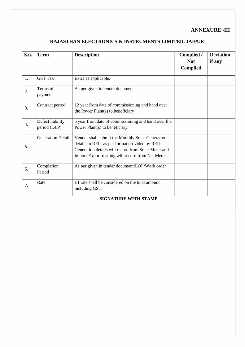
ANNEXURE -III
RAJASTHAN ELECTRONICS & INSTRUMENTS LIMITED, JAIPUR
S.n. Term Description Complied /
Not
Complied
Deviation
if any
1. GST Tax Extra as applicable.
2. Terms of
payment
As per given in tender document
3. Contract period 12 year from date of commissioning and hand over
the Power Plant(s) to beneficiary
4. Defect liability
period (DLP)
5 year from date of commissioning and hand over the
Power Plant(s) to beneficiary
5.
Generation Detail Vender shall submit the Monthly Solar Generation
details to REIL as per format provided by REIL.
Generation details will record from Solar Meter and
Import-Export reading will record from Net Meter
6. Completion
Period
As per given in tender document/LOI /Work order
7. Rate L1 rate shall be considered on the total amount
including GST.
SIGNATURE WITH STAMP

Annexure -IV
RAJASTHAN ELECTRONICS & INSTRUMENTS LIMITED, JAIPUR
Authorization Certificate
To
Date
Dy. General Manager (Proc.),
Rajasthan Electronics & Instruments Limited,
2, Kanakpura Industrial Area,
Jaipur-302034
Rajasthan
Dear Sir,
We M/s. ……………………..are authorizing M/s. ……………………………….. to submit tender
document in reference to your tender no REIL/RE/19-20/PP/19135 dated …….. for Supply of BOS,
installation-commissioning & 12 year‟s maintenance period of 200kWp grid connected SPV Power
Plant(s) at Rooftop of various Govt. buildings in Udaipur.
On behalf of company ………………………
Name and Designation
Signed and sealed (who has signed the tender)

Annexure -V
Maintenance Certificate
Date-
Name of Site:-
Location of Site:-
Capacity of SPV Power Plant:-
Type of SPV Power Plant :- Grid Connected
Contact Person:-
S.NO
.
DESCRIPTION STATUS REMARK
1. Nos. of SPV Modules & Capacity
2. Cleaning of Modules on
Date……………
3. Nos. of String Inverter & Capacity
4. Sr. No. of String Inverter
5. Nos. of Strings
6. Nos. of Modules in each String
7. Vmp & Imp of Strings Nos. Vmp Imp
8. Reading of String Inverters Power
(kW)
E-Today
(kWh)
Cumulative (kWh)
9. Solar Meter Details
Sr. No.
Make
…………………………..kWh
10. Net Meter Details
Sr.No.
Make
Import kWh Export kWh Net kWh
11. If/Any
It is certified that the Grid Connected SPV Power Plant Capacity of ………….kWp at ……………… (Location)
is working satisfactory.
Signature of REIL
Signature of Beneficiary

Annexure-VI
RAJASTHAN ELECTRONICS & INSTRUMENTS LIMITED, JAIPUR
Tender ref. REIL/RE/19-20/PP/19135
UNDERTAKING OF NO NEAR RELATIVE
To
Date
DGM (PROC),
Rajasthan Electronics & Instruments Limited,
2, Kanakpura Industrial Area,
Jaipur-302034
Rajasthan
Dear Sir,
I………………………………S/o…………………………………… R/o………………………
hereby certify that none of my relatives) as defined in the tender document is/are employed in REIL
unit as per details given in tender document. In case at any stage, it is found that the information
given by m is false/incorrect, REIL shall have the absolute right to take any action as deemed
fit/without any prior intimation to me.
On behalf of company ………………………
Name and Designation

Annexure -VII
RAJASTHAN ELECTRONICS & INSTRUMENTS LIMITED, JAIPUR
Check List
Sr. No. Required Documents Remark
1. Sealed and signed process compliance form. (Annexure-I)
2. Sealed and signed scope of work (Annexure-II)
3. Sealed and signed General terms & conditions of tender (Annexure-III)
4. Authorization certificate ( Annexure-IV)
5. Maintenance certificate format for maintenance period (Annexure –V)
6. Sealed & signed Undertaking of No Near Relative (Annexure VI)
7. Check list (Annexure-VII)

PERFORMA (EMD)
BANK GUARANTEE TOWARDS EARNEST MONEY DEPOSIT
Bank Guarantee No.
Date
To,
Rajasthan Electronics & Instruments Limited, (REIL)
2, Kanakpura Industrial Area Sirsi Road,
Jaipur-302034 (Rajasthan)
Dear Sir,
In accordance with Invitation for Bids under your Bid Document No.………………………… dated
……………).M/s. …………………………………(Bidder Name) having its registered office at
…………......................‟ (hereinafter called the bidder) wish to participate in the said Bid for Supply of
BOS, installation-commissioning & 12 year‟s maintenance period of 200 kW Grid Connected Solar PV
Plant at Titardi, Udaipur ,Rajasthan
As an irrevocable bank guarantee against Bid Security for an amount of Rs.One Lac Fifty Thousand
only (Rs. 1,50,000/- only) valid up to …………………, required to be submitted by the Bidder as a
condition precedent for participation in the said Bid which amount is liable to be forfeited on the
happening of any contingencies mentioned in the Bidding Documents.
We, the …………………………………………………………..(Bank Name & address) guarantee and
undertake to pay immediately on demand by Rajasthan Electronics & Instruments Limited the amount
of Rs. One Lac Fifty Thousand only (Rs. 1,50,000/- only) without any reservation, protest, demand and
recourse. Any such demand made by the „REIL‟ shall be conclusive and binding on us irrespective of
any dispute or difference raised by the Bidder.
This Guarantee shall be irrevocable and shall remain valid up to ……………………..(date of expiry of
Guarantee).. If any further extension of this guarantee is required, the same shall be extended to such
required period (not exceeding one year) on receiving instructions from M/s.
……………………………………………..(Bidder Name) on whose behalf this guarantee is issued.
This guarantee will remain in force up to and including …………………………..(date of expiry of
Guarantee). , and any demand in respect thereof must reach the Bank not later than the above date.

Not withstanding anything contained herein above:
i) Our liability under this guarantee shall not exceed Rs. One Lac Fifty Thousand only (Rs.
1,50,000/- only)
ii) This bank guarantee shall be valid up to ……………….(date of expiry of Guarantee).
iii) We are liable to pay the guaranteed amount or any part thereof under this Bank Guarantee only
and only if we receive from you a written claim or demand on or before …………. (date of
expiry of Guarantee).
The said letter of guarantee has been transmitted through SFMS gateway to your bank. It is advised that
in your own interest, you may verify the genuineness of above letter of guarantee from your bank /
branch.
Dated the date of 2019.
Bank Name
(sealed& signed)

TO WHOM SO EVER IT MAY CONCERN
Bank details of e- payment
1. Name & Address :Rajasthan Electronics & Instruments Ltd., Jaipur
2 Kanakpura Industrial Area Sirsi Road, Jaipur
2. Contact No
: Tel.: (0141) 2470908,
Fax No. 0141-2470531
3. Name of the bankers
: Punjab National Bank, Mid Corporate Branch, M. I. Road, Jaipur
(Raj.) (Branch Code 0221)
4.MICR Code No. : 302024003
5. Bank Account No.
: 0221008700000152 (Cash-Credit account)
6. RTGS/IFSC Code No.
: PUNB 0022100
7. PAN No. : AABCR1528G
8. Service Tax No.
9. TIN No /VAT No.
10. CST No.
11. GST IN
: AABCR1528GST001
: 08202102675
: 1421/02723DT-18.01.1982
: 08AABCR1528G1ZL

Annexure-F Project Report Format
Format for Summary Project Report “Implementation of 200 KW Rooftop mounted Grid connected
Solar PV plant at Cattle House waste processing facility, Titardi . Udaipur”
1. Name of Bidder
2. RFS no.
3. Project details (Site location & Address)
4. Brief about the Rooftop Solar Power Generation System
5. Specifications of the Components and Bill of Material/ Quantities
Sl. no
Component
Specifications Quantity
Make
A Solar PV module
A.1 Aggregate Solar PV capacity (MWp)
B Grid Tie inverter (Type and Capacity)
B.1 Aggregate Inverter capacity (kVA)
C
Module mounting structure (Certified by
a Structural Engineer(Mandatory for this
project )
D Array Junction Box
E AC Distribution Board
F Cable (All type)
G LA &Earthing Kit(maintenance free)
H Meters
I Online monitoring system
J Any other component
K Transformer and Switch Gear
M
Transmission Line from plant substation
to nearby 11 kV GIS
7. Unit cost of solar power generation
8. Cost benefit analysis, payback period
9. Expected output/annum
10. Detailed drawings for plant layout, Plant electrical wiring connections, earthing
arrangement, Structural details and other components etc.
11. Connectivity details with grid and metering arrangement (with sketch diagram)
12. Detailed mounting and lay out drawing of switch yard inside the solar power plant
13. Any other information which may be important but missing from this list

(The above information should be limited up to 2-3 pages only)

Annexure H
Project Completion Report for 200 KW AC Rooftop mounted Grid-Connected solar plant at Titardi
Udaipur
Financial year *:
Approval No. * :
Proposal Title:
Installed by agency:
Project initiated by:
Title of the Project* :
Capacity (MWp)*:
Category of the organization * : Name of the
contact person* :
Address of contact person* :
State* : District/City* :
Mobile* : Email* :
Telephone No. : STD code- Website :
Other info
Electricity Distribution Company
Name :
Electricity consumer account no. as per as on Date :
electricity bill :
project owner:-
Name of Bank:
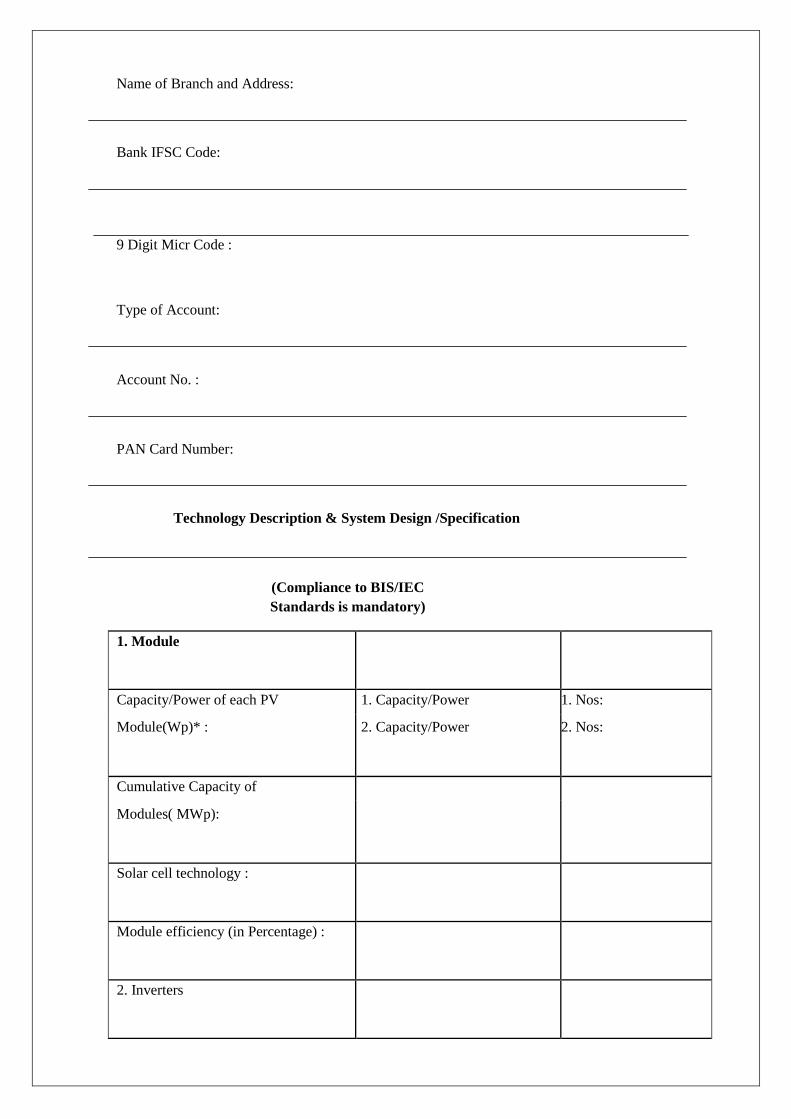
Name of Branch and Address:
Bank IFSC Code:
9 Digit Micr Code :
Type of Account:
Account No. :
PAN Card Number:
Technology Description & System Design /Specification
(Compliance to BIS/IEC
Standards is mandatory)
1. Module
Capacity/Power of each PV 1. Capacity/Power 1. Nos:
Module(Wp)* : 2. Capacity/Power 2. Nos:
Cumulative Capacity of
Modules( MWp):
Solar cell technology :
Module efficiency (in Percentage) :
2. Inverters

Type of inverter :
Make of inverter :
Capacity/Power of each Capacity/Power
PCU/inverters (VA)* : Nos.
Capacity/Power of PCU/inverters
(KVA) :
Inverter efficiency (Full load) :
(in percentage)
3. Metering Arrangement
Details of Metering
Type of Meter* :
Make of Meter :
5. Other information
Units of electricity generated by the
solar plant as per meter (in KWh):
Monitoring Mechanism :
No. of personnel to be trained in O&M

:
Task & Expected Schedule(in Months)
:
Grid connectivity level
Grid connectivity level phase* : Grid connectivity
level Voltage* :