Embed Size (px)
Citation preview

RAILWAYS Formation & dewatering
Jarosław Zwolski, PhD CE
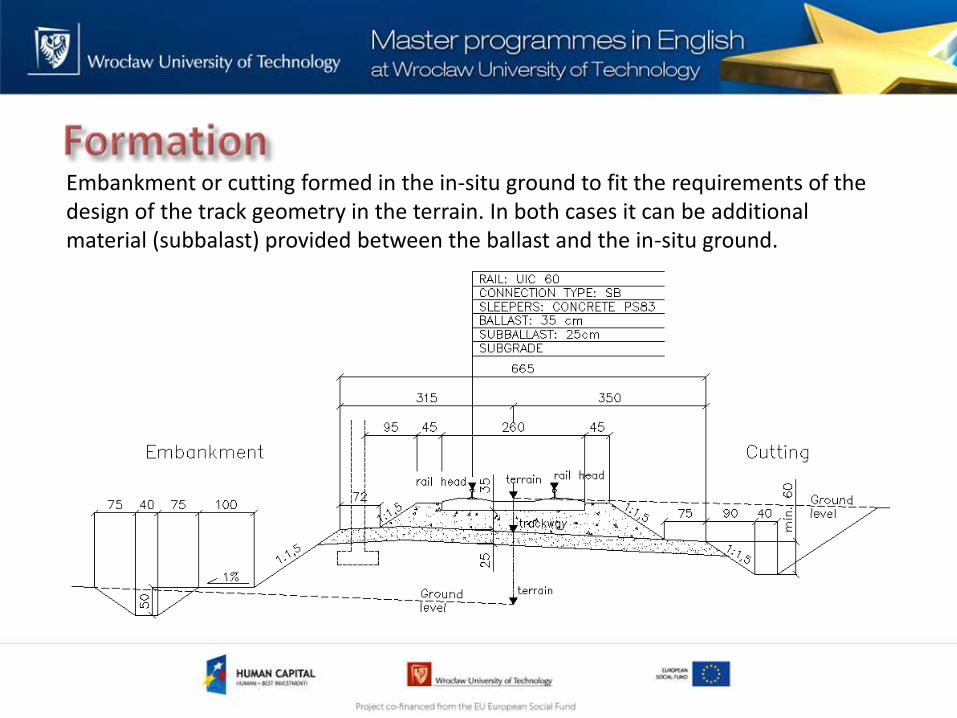
Embankment or cutting formed in the in-situ ground to fit the requirements of the design of the track geometry in the terrain. In both cases it can be additional material (subbalast) provided between the ballast and the in-situ ground.

Transfer of load from sleepers to the ground.
Damping of vibrations excited by vehicles.
Fast dewatering of the ballast by appropriate layers of subballast and transverse slopes.
Preventing mixing the ground from lower layers with the ballast.
Strength and durability of the ground used as a material to build in.
Good compactible characteristic (easy to compact), easy to soak through for water and freeze resistant.
Stable and uniform properties of the ground on the section of the track (to avoid the threshold effect).
Aprioppriate shape and slopes.
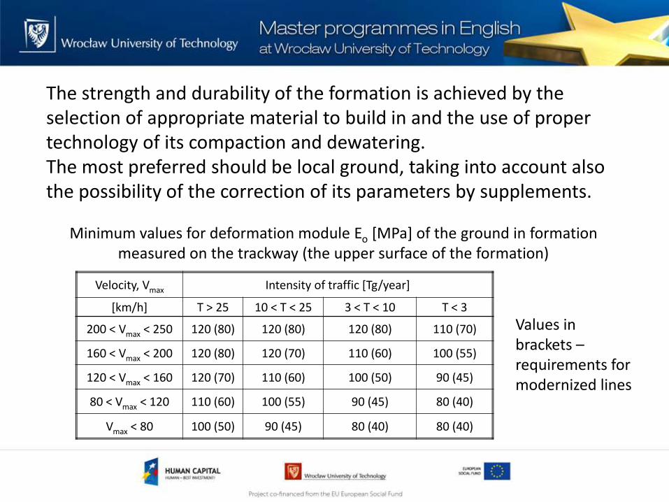
The strength and durability of the formation is achieved by the selection of appropriate material to build in and the use of proper technology of its compaction and dewatering. The most preferred should be local ground, taking into account also the possibility of the correction of its parameters by supplements.
Minimum values for deformation module Eo [MPa] of the ground in formation measured on the trackway (the upper surface of the formation)
Values in brackets – requirements for modernized lines
Velocity, Vmax Intensity of traffic [Tg/year]
[km/h] T > 25 10 < T < 25 3 < T < 10 T < 3
200 < Vmax < 250 120 (80) 120 (80) 120 (80) 110 (70)
160 < Vmax < 200 120 (80) 120 (70) 110 (60) 100 (55)
120 < Vmax < 160 120 (70) 110 (60) 100 (50) 90 (45)
80 < Vmax < 120 110 (60) 100 (55) 90 (45) 80 (40)
Vmax < 80 100 (50) 90 (45) 80 (40) 80 (40)
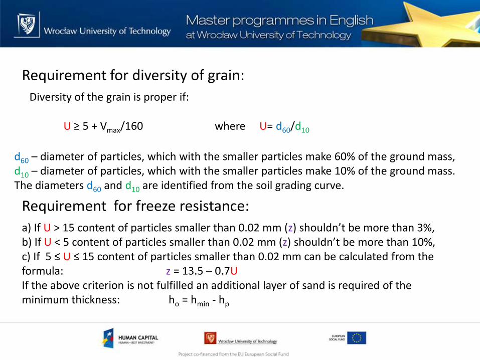
Requirement for diversity of grain:
Diversity of the grain is proper if:
where U= d60/d10
d60 – diameter of particles, which with the smaller particles make 60% of the ground mass, d10 – diameter of particles, which with the smaller particles make 10% of the ground mass. The diameters d60 and d10 are identified from the soil grading curve.
Requirement for freeze resistance:
a) If U > 15 content of particles smaller than 0.02 mm (z) shouldn’t be more than 3%, b) If U < 5 content of particles smaller than 0.02 mm (z) shouldn’t be more than 10%, c) If 5 ≤ U ≤ 15 content of particles smaller than 0.02 mm can be calculated from the formula: z = 13.5 – 0.7U If the above criterion is not fulfilled an additional layer of sand is required of the minimum thickness: ho = hmin - hp
U ≥ 5 + Vmax/160

Soil grading curve
d60 d10
FRACTION
SILT
DIAMETER [mm]
CO
NTE
NTS
OF
PAR
TIC
LES
WIT
H A
DIA
MET
ER L
ESS
THA
N
CO
NTE
NTS
OF
PAR
TIC
LES
WIT
H A
DIA
MET
ER M
OR
E TH
AN
SAND CLAY GRAVEL STONE
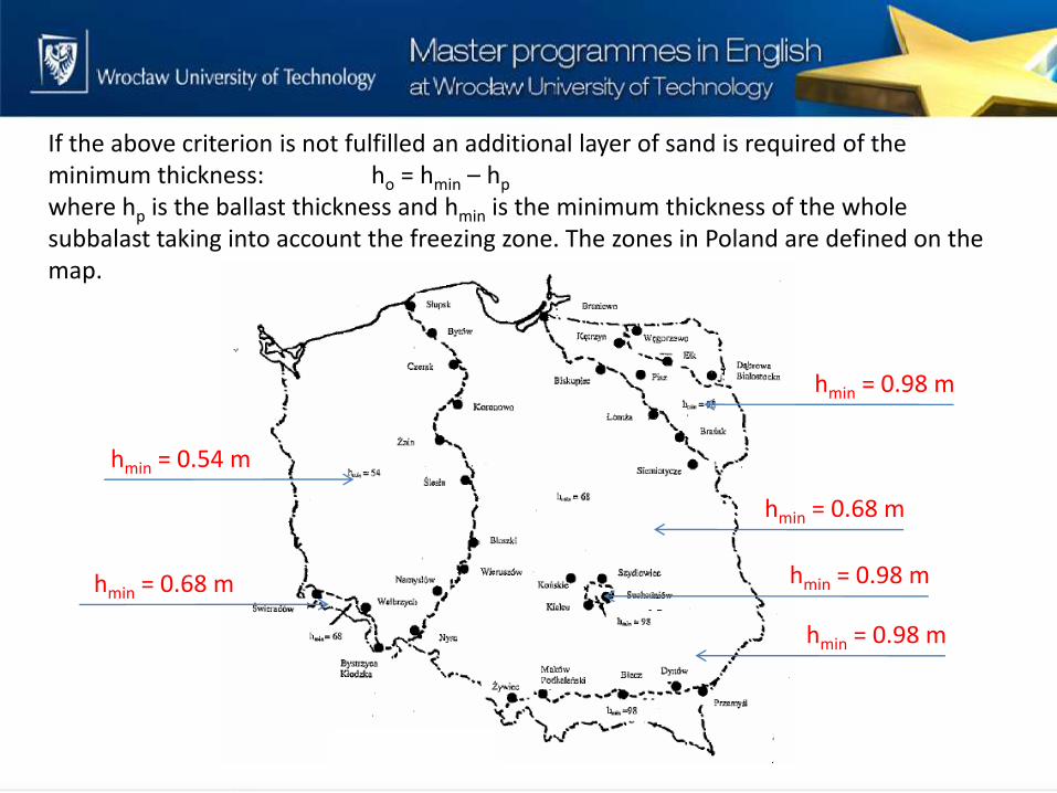
If the above criterion is not fulfilled an additional layer of sand is required of the minimum thickness: ho = hmin – hp
where hp is the ballast thickness and hmin is the minimum thickness of the whole subbalast taking into account the freezing zone. The zones in Poland are defined on the map.
hmin = 0.68 m
hmin = 0.98 m
hmin = 0.98 m
hmin = 0.54 m
hmin = 0.68 m hmin = 0.98 m
hmin = 0.54 m
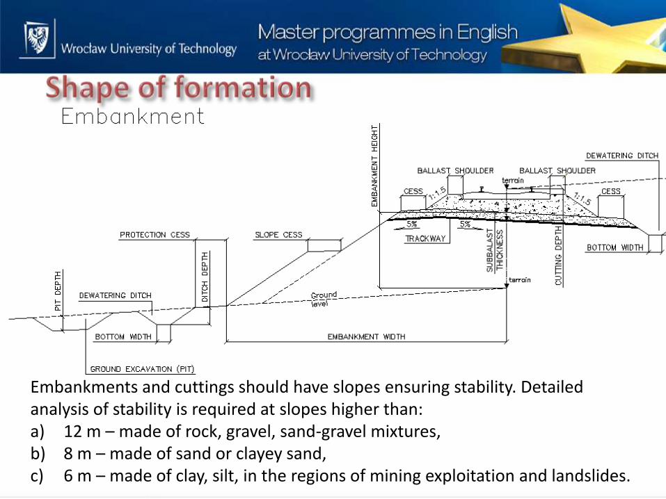
Embankments and cuttings should have slopes ensuring stability. Detailed analysis of stability is required at slopes higher than: a) 12 m – made of rock, gravel, sand-gravel mixtures, b) 8 m – made of sand or clayey sand, c) 6 m – made of clay, silt, in the regions of mining exploitation and landslides.
1. Dewatering should be used as one of the main ways of increasing ground capacity and stability of formation.
2. Formation should be dewatered by the proper shaping of slopes and using filtration and/or sealing materials if needed as well as using ditches and underground drainage. Ground water should be removed using deep drainage which doesn’t freeze at low temperatures.
3. On lines surface water is removed from ballast using transversal inclination of trackway (3-5%) in the direction of the side ditches or underground drainage.
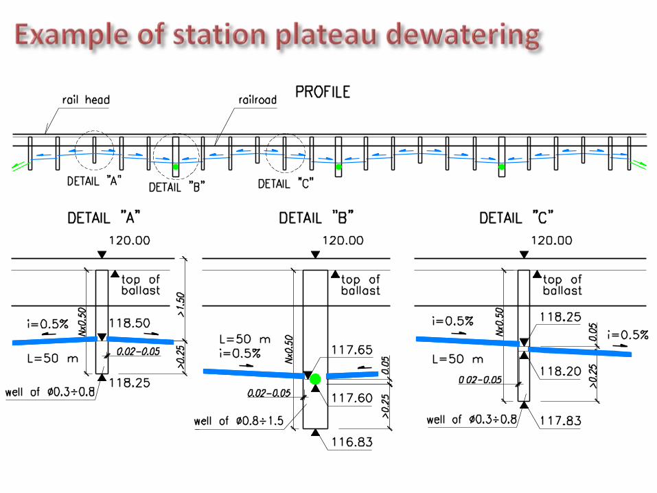
4. On stations surface water is removed by so called plate drainage: building a filtration layer with transversal inclination of 2-4% and removing water to side ditches and to internal shallow drainage located in every 2 or 4 space between tracks.
5. Other surfaces of the formation (cess, protection cess, surfaces of non-permeable grounds located under easy permeable grounds, except slopes) are shaped with an inclination of 5%.

1. Linear surface drainage (ditches, gutters, embankments). 2. Linear underground drainage with a dewatering system of
pipes and auxiliary installations. 3. Plate drainage (e.g. drainage layers on the station
plateau). 4. Slope drainage. 5. Vertical drainage. 6. Special and auxiliary devices.
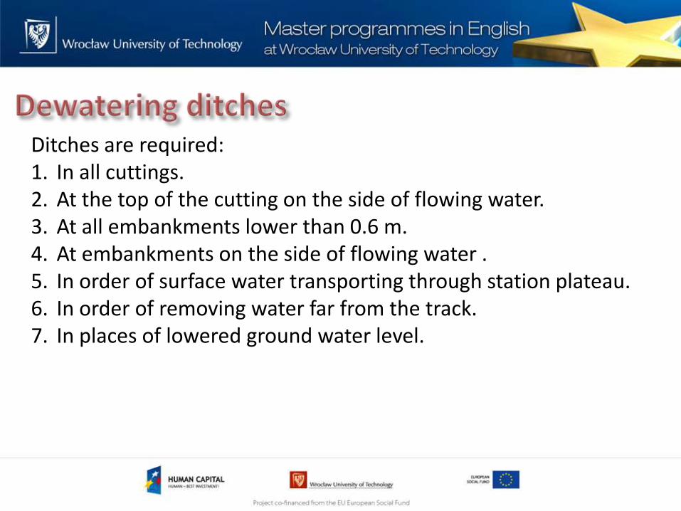
Ditches are required: 1. In all cuttings. 2. At the top of the cutting on the side of flowing water. 3. At all embankments lower than 0.6 m. 4. At embankments on the side of flowing water . 5. In order of surface water transporting through station plateau. 6. In order of removing water far from the track. 7. In places of lowered ground water level.

Formation Ground type Slope
Sandy clay, sandy clay loam 1.5 - 1.8, 1.7 - 1.8 1)
Pebbles, gravel, coarse sand and mixtures 1.5 - 1.8
Boulders resistant to weathering 1.3 - 1.7 2)
Very fine sand 2
Sand, sandy clay, pebbles, gravel, coarse sand and mixtures 1.5 - 1.7 3)
Cohesive soil 1.5 - 2.0 4)
Loess in very dry conditions 0.1 - 0.5 5)
Rocks resistant to weathering 0.2 - 1.0 6)
Rocks non-resistant to weathering 0.5 - 1.51) in very wet regions2) low values applicable for formation of layers; in case of boulders shelves or retention walls could be required3) lower values applicable for dry clayey soils, cemented sands etc. and depending on the cutting depth (e.g.
at the cutting to 8 m – 1.25; deeper – 1.5)4) depending on the cuting depth and characteristic of soil5) stability in various humidity conditions should be checked6) at the slope base a protection against falling pebbles is required (e.g. a shelf with an embankment)
Cutting
Embankment

Cross-sections of formation in the zone of a ditch: a) cutting (railway line), b) embankment (railway line), c) embankment on flooding terrain, d) cutting (big railway station)
Protective layer
Protective layer
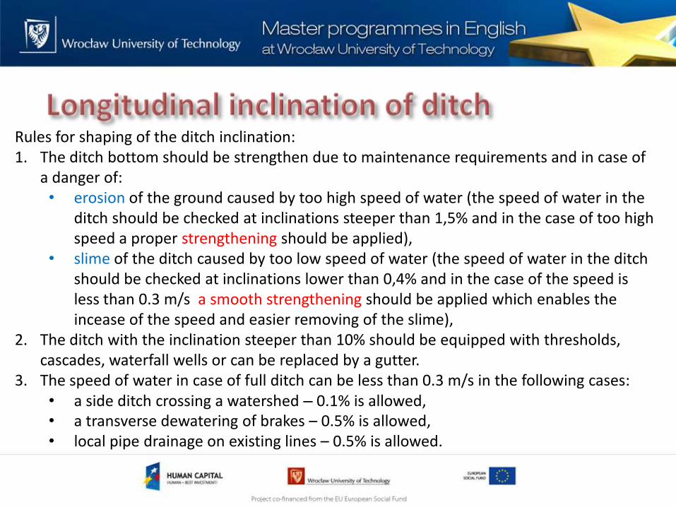
Rules for shaping of the ditch inclination: 1. The ditch bottom should be strengthen due to maintenance requirements and in case of
a danger of: • erosion of the ground caused by too high speed of water (the speed of water in the
ditch should be checked at inclinations steeper than 1,5% and in the case of too high speed a proper strengthening should be applied),
• slime of the ditch caused by too low speed of water (the speed of water in the ditch should be checked at inclinations lower than 0,4% and in the case of the speed is less than 0.3 m/s a smooth strengthening should be applied which enables the incease of the speed and easier removing of the slime),
2. The ditch with the inclination steeper than 10% should be equipped with thresholds, cascades, waterfall wells or can be replaced by a gutter.
3. The speed of water in case of full ditch can be less than 0.3 m/s in the following cases: • a side ditch crossing a watershed – 0.1% is allowed, • a transverse dewatering of brakes – 0.5% is allowed, • local pipe drainage on existing lines – 0.5% is allowed.
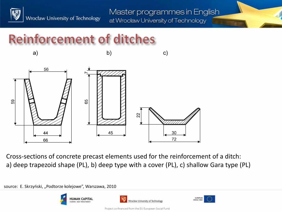
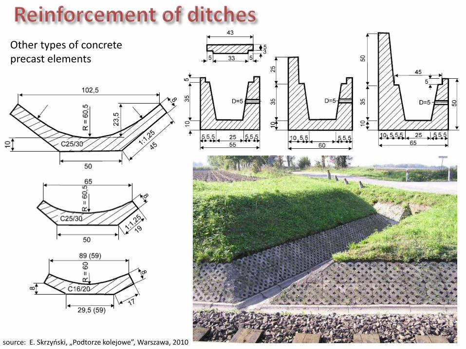
Cross-sections of concrete precast elements used for the reinforcement of a ditch: a) deep trapezoid shape (PL), b) deep type with a cover (PL), c) shallow Gara type (PL)
g railway station )
source: E. Skrzyński, „Podtorze kolejowe”, Warszawa, 2010
source: E. Skrzyński, „Podtorze kolejowe”, Warszawa, 2010
Other types of concrete precast elements
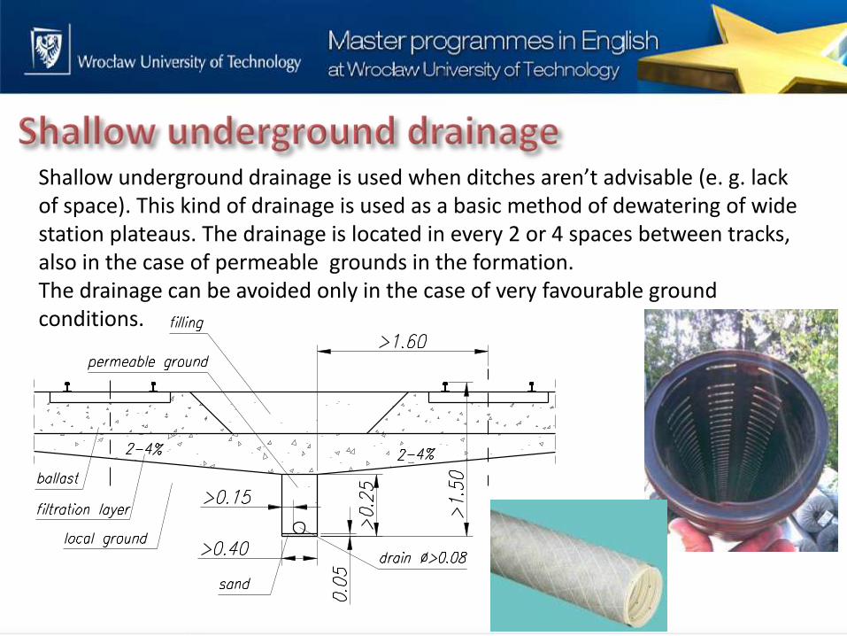
Shallow underground drainage is used when ditches aren’t advisable (e. g. lack of space). This kind of drainage is used as a basic method of dewatering of wide station plateaus. The drainage is located in every 2 or 4 spaces between tracks, also in the case of permeable grounds in the formation. The drainage can be avoided only in the case of very favourable ground conditions.


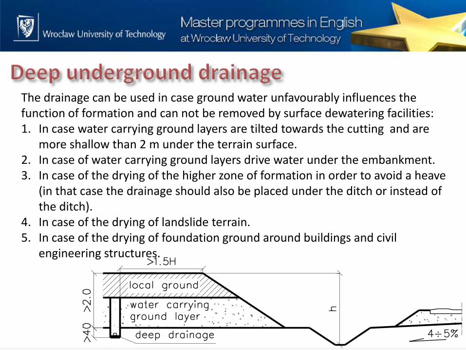
The drainage can be used in case ground water unfavourably influences the function of formation and can not be removed by surface dewatering facilities: 1. In case water carrying ground layers are tilted towards the cutting and are
more shallow than 2 m under the terrain surface. 2. In case of water carrying ground layers drive water under the embankment. 3. In case of the drying of the higher zone of formation in order to avoid a heave
(in that case the drainage should also be placed under the ditch or instead of the ditch).
4. In case of the drying of landslide terrain. 5. In case of the drying of foundation ground around buildings and civil
engineering structures.
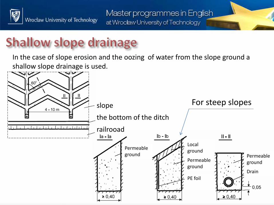
In the case of slope erosion and the oozing of water from the slope ground a shallow slope drainage is used.
slope
the bottom of the ditch
railrooad
Permeable ground
Local ground
Permeable ground
PE foil
Permeable ground
Drain
For steep slopes

In the case of slope erosion, landslides and the oozing of water from the slope ground a shallow slope drainage can also be used.
Continuous filtration layer
Drainage
Water carrying layer Reinforced drain outlet Water carrying layer
Reinforced slope
Drainage with permeable ground 0,8-2,0 m
Permeable ground 0,8-2,0 m
Collector pipe in permeable ground
Deep drainage
Permeable ground 0,8-2,0 m
Drainage with permeable ground 0,8-2,0 m
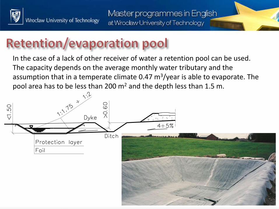
In the case of a lack of other receiver of water a retention pool can be used. The capacity depends on the average monthly water tributary and the assumption that in a temperate climate 0.47 m3/year is able to evaporate. The pool area has to be less than 200 m2 and the depth less than 1.5 m.
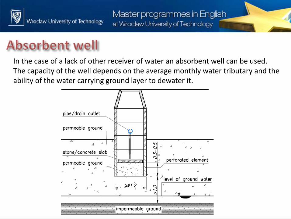
In the case of a lack of other receiver of water an absorbent well can be used. The capacity of the well depends on the average monthly water tributary and the ability of the water carrying ground layer to dewater it.
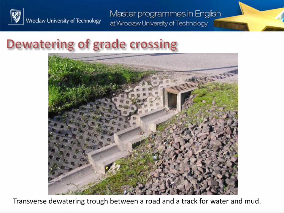
Transverse dewatering trough between a road and a track for water and mud.
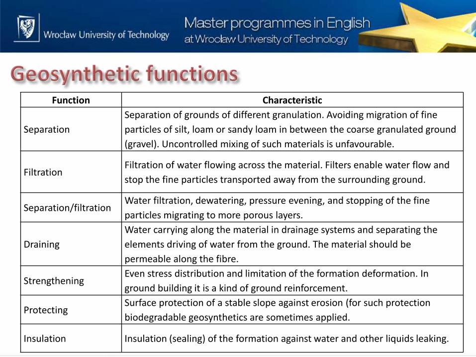
Function Characteristic
Separation
Separation of grounds of different granulation. Avoiding migration of fine
particles of silt, loam or sandy loam in between the coarse granulated ground
(gravel). Uncontrolled mixing of such materials is unfavourable.
Filtration Filtration of water flowing across the material. Filters enable water flow and
stop the fine particles transported away from the surrounding ground.
Separation/filtration Water filtration, dewatering, pressure evening, and stopping of the fine
particles migrating to more porous layers.
Draining
Water carrying along the material in drainage systems and separating the
elements driving of water from the ground. The material should be
permeable along the fibre.
Strengthening Even stress distribution and limitation of the formation deformation. In
ground building it is a kind of ground reinforcement.
Protecting Surface protection of a stable slope against erosion (for such protection
biodegradable geosynthetics are sometimes applied.
Insulation Insulation (sealing) of the formation against water and other liquids leaking.

1. Strenghtening of formation.
Exceptionally under the ballast
Under the subballast layer
Reinforcement of the subballast layer
geosynthetic geosynthetic geosynthetic
subballast
subballast
subballast

2. Strenghtening of the foundation of an embankment
geosynthetic
embankment
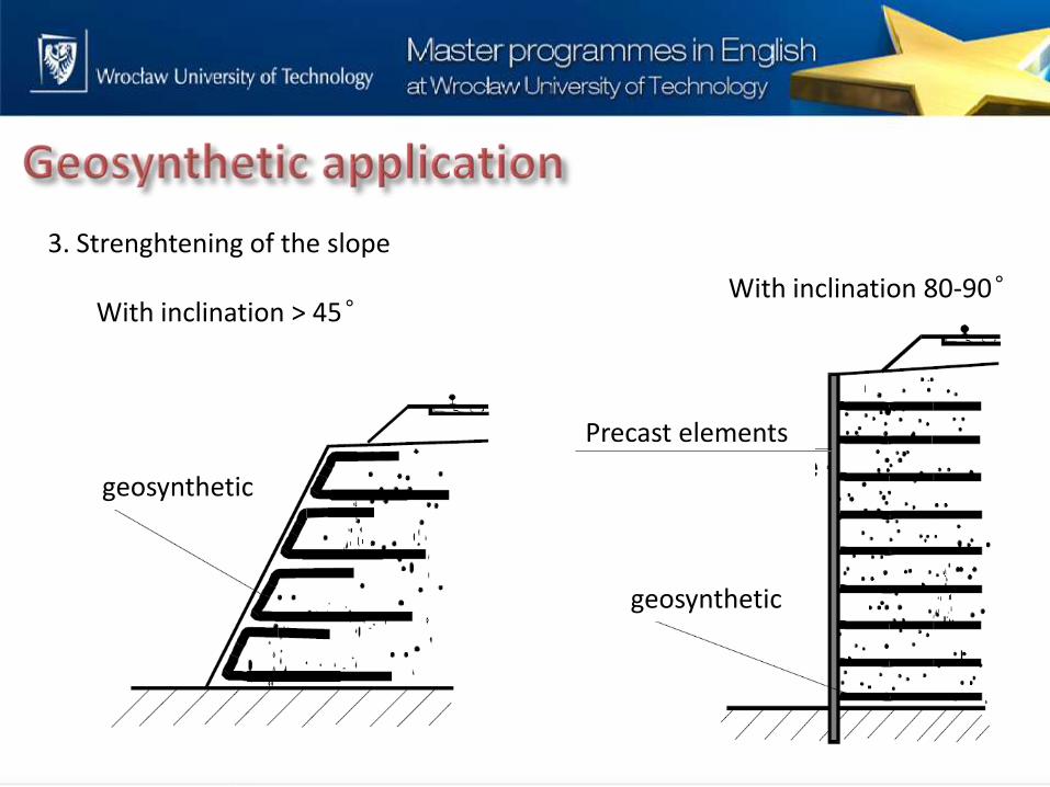
3. Strenghtening of the slope
With inclination > 45˚
geosynthetic
With inclination 80-90˚
geosynthetic
Precast elements
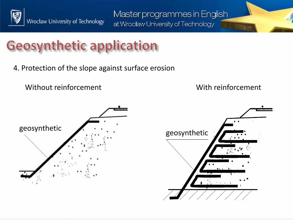
4. Protection of the slope against surface erosion
Without reinforcement With reinforcement
geosynthetic geosynthetic

5. Filtration/drainage
Pipe drainage Stone drainage
(French application)
geotextiles
drain drain
geotextiles geotextiles
Stone drain
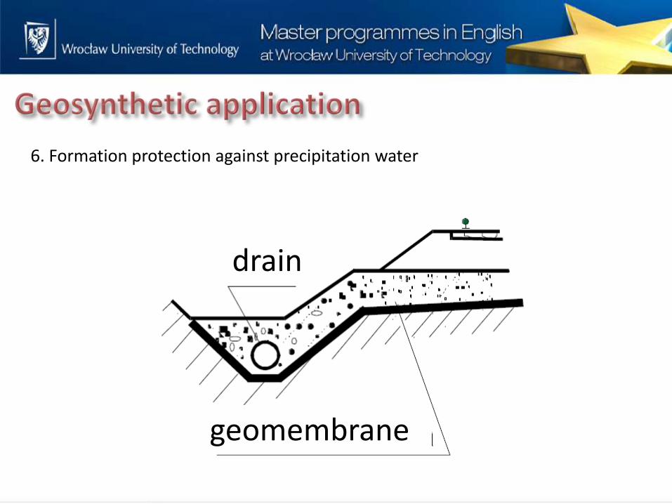
6. Formation protection against precipitation water
geomembrane
drain