Embed Size (px)
Citation preview
Rafael Space Propulsion
CATALOGUE
A
B
C
D
E
F
G
Proprietary Notice This document includes data proprietary to
Rafael Ltd. and shall not be duplicated, used, or disclosed, in whole or in part, for any purpose without written authorization from Rafael Ltd.
Rafael Space Propulsion
INTRODUCTION AND OVERVIEW
PART A: HERITAGE
PART B: SATELLITE PROPULSION SYSTEMS
PART C: PROPELLANT TANKS
PART D: PROPULSION THRUSTERS Satellites Launchers
PART E: PROPULSION SYSTEM VALVES
PART F: SPACE PRODUCTION CAPABILITIES
PART G: QUALITY MANAGEMENT
CATALOGUE – Version 2 | 2019

Heritage PART A
0
Heritage

Heritage PART A
1
Rafael Introduction and Overview
Rafael Advanced Defense Systems Ltd. designs, develops, manufactures and supplies a wide range of high-tech systems for air, land, sea and space applications.
Rafael was established as part of the Ministry of Defense more than 70 years ago and was incorporated in 2002. Currently, 7% of its sales are re-invested in R&D. Rafael’s know-how is embedded in almost every operational Israel Defense Forces (IDF) system; the company has a special relationship with the IDF.
Rafael has formed partnerships with companies with leading aerospace and defense companies worldwide to develop applications based on its proprietary technologies. Offset activities and industrial co-operations have been set-up with more than 20 countries world-wide. Over the last decade, international business activities have been steadily expanding across the globe, with Rafael acting as either prime-contractor or subcontractor, capitalizing on its strengths at both system and sub-system levels.
Rafael’s highly skilled and dedicated workforce tackles complex projects, from initial development phases, through prototype, production and acceptance tests. Rafael offers a full range of customer service and support, from upgrading of existing systems up to turnkey projects, from transfer of basic technologies to complete production facilities.
Rafael’s quality management system is certified to AS9100C (AS9100D in process), ISO9001, ISO14001, ISO27001, ISO90003, OHSAS 18001. The environmental tests facilities, metallurgy laboratory and calibration laboratory are certified to ISO17025
Rafael aims to enhance its acclaim as a world-class provider of quality defense products and excellent customer service. It will continue to predict future aerospace requirements worldwide and provide the technologies and systems required by our customers.

Heritage PART A
2
Manor Advanced Defense Technology Division
The Manor Advanced Defense Technologies Division develops and manufactures propulsion systems, composite materials, and pyrotechnic devices for all Rafael’s systems, as well as for domestic and international customers.
Manor Division is engaged in every aspect of product development and manufacturing, from specification and design to manufacturing and integrated logistics support.
Comprehensive analytic tools and facilities are available in-house, covering all aspects of research, design, development, manufacturing and testing of solid and liquid propellant rocket motors, hydrazine mono-propellant space propulsion systems electric space propulsion systems as well as propellant reservoir tanks.
Manor Division possesses the infrastructure necessary for the research, development and production of solid and liquid propellant rocket motors, their components and, in some cases, the raw materials. Modern computerized laboratories have been set up for synthesis and characterization of advanced binders, bonding agents, burning rate catalysts and other propellant ingredients.
Manor’s testing facilities include a variety of computerized static firing cells, including a high-altitude and space simulation cells, as well as environmental testing facilities.

Heritage PART A
3
Rafael's Space Capabilities
Rafael’s space activities are focused on Space Propulsion, Composite materials, Micro-Satellite technologies and airborne launchers.
Rafael has gained extensive experience in developing, qualifying and producing controllable propulsion and reaction control systems, based on both hot gas (gas generators, solid rocket motors and hydrazine thrusters) and cold gas (mainly nitrogen) for space applications.
Rafael propulsion modules or components are integrated in over seventy in-orbit satellites. Rafael complete propulsion modules are on board the OFEQ, EROS, TecSAR and other satellites. Rafael furnished the propellant tanks and hydrazine thrusters for the Galileo IOV, Globalstar-2 constellations, O3B constellations, SENTINEL-1 constellations, NEOSAT, SAC-D, IXV, EXOMARS 2016 and 2020, COSMO SG, CERES, SAOCOM and others.
Rafael joint CNES\ ISA dual mission (scientific/ technological) Venµs satellite, successfully launched in 2017, incorporates Rafael’s qualified Electric Propulsion system.
All Rafael propulsion systems and components in space have demonstrated 100% mission success, with no system or component failures, or loss of redundancy.
As part of its long-term strategy, Rafael invests in micro-satellite-related technologies and concepts, for improved mission solutions. Rafael intends to introduce missile technologies in terms of miniaturization and performance.
Rafael is studying the concept of mission-on-demand, for micro-satellite application, and intends to develop a dedicated airborne launcher that enables using a fighter-aircraft or a jet-liner as launching platform, to enable affordable, flexible mission-on-demand implementation.

Heritage PART A
4
Satellite Propulsion Systems (PS): Hydrazine (HPS), Cold Gas, Electric Hall Effect
Sat. Program
Product Name Customer Comments
1
OFEQ OFEQ 3 OFEQ 5 OFEQ 7 OFEQ 9 OFEQ 10 OFEQ 11
Hydrazine Propulsion systems (HPS)
IAI/MBT, Israel
1. OFEQ 3, launched in 1995; fully operational in-orbit 2. OFEQ 5, launched in 2002; fully operational in-orbit 3. OFEQ 7, launched in 2007; fully operational in-orbit 4. OFEQ 9, launched in 2010; fully operational in-orbit 5. OFEQ 10, launched in 2014; fully operational in-orbit 6. OFEQ 11, launched in 2016; fully operational in-orbit Their RAFAEL propulsion systems consist of:
• 5N / 1N thrusters – 12 or 8 • 25N thrusters – 2 • 30 liters hydrazine tank – 1 (PEPT-420) • Latch valves – 2 • Filters – 2 • Pressure transducers – 2 • Fill and drain/vent valves – 2 • Manifolds, brackets & wiring
2 EROS
EROS A1 EROS B
HPS IAI/MBT, Israel
1. EROS A1, launched in 2000; fully operational in-orbit 2. EROS B, launched in 2006; fully operational in-orbit Their RAFAEL propulsion systems consists of:
• 5N / 1N thrusters – 12 • 25N thrusters – 2 • 30 liters hydrazine tank – 1 (PEPT-420) • Latch valves – 2 • Filters – 2 • Pressure transducers – 2 • Fill and drain/vent valves – 2 • Manifolds, brackets & wiring
3 TECSAR HPS IAI/MBT, Israel
TECSAR, launched in 2008 ; fully operational in-orbit The RAFAEL propulsion systems consists of:
• 5N thrusters • 25N thrusters • 30 liters hydrazine tank (PEPT-420) • Latch valves • Filters • Pressure transducers • Fill and drain/vent valves • Manifolds, brackets & wiring

Heritage PART A
5
Hydrazine (HPS), Cold Gas, Electric Hall Effect
Sat. Program
Product Name Customer Comments
4 Venµs HPS ISA/CNES
Venµs Satellite, launched in 2017; fully operational in-orbit The RAFAEL Hydrazine Propulsion system consists of: • 1N thrusters – 8 • PEPT-260 hydrazine tank –1 • Latch valves – 2 • Filters – 1 • Pressure transducer – 2 • Fill and Drain/Vent valves – 2 • Manifolds, brackets & wiring
5 Venµs Electric Hall Effect ISA/CNES
The RAFAEL Electrical Propulsion consists of: • HET-300 thrusters (15 mN @ 300W anodic) - 2 • PPU : 250W to 600W • Xenon tank: 9 liters • DXFC : Digital Xenon Flow Controller • Pressure reduction system and valves
6 Slosh -Sat
Cold Gas Sat.
Reaction Control System
NRL- Netherland
s
Qualified by NASA and ESA Space proven, launched in 2005
Heritage PART A
6
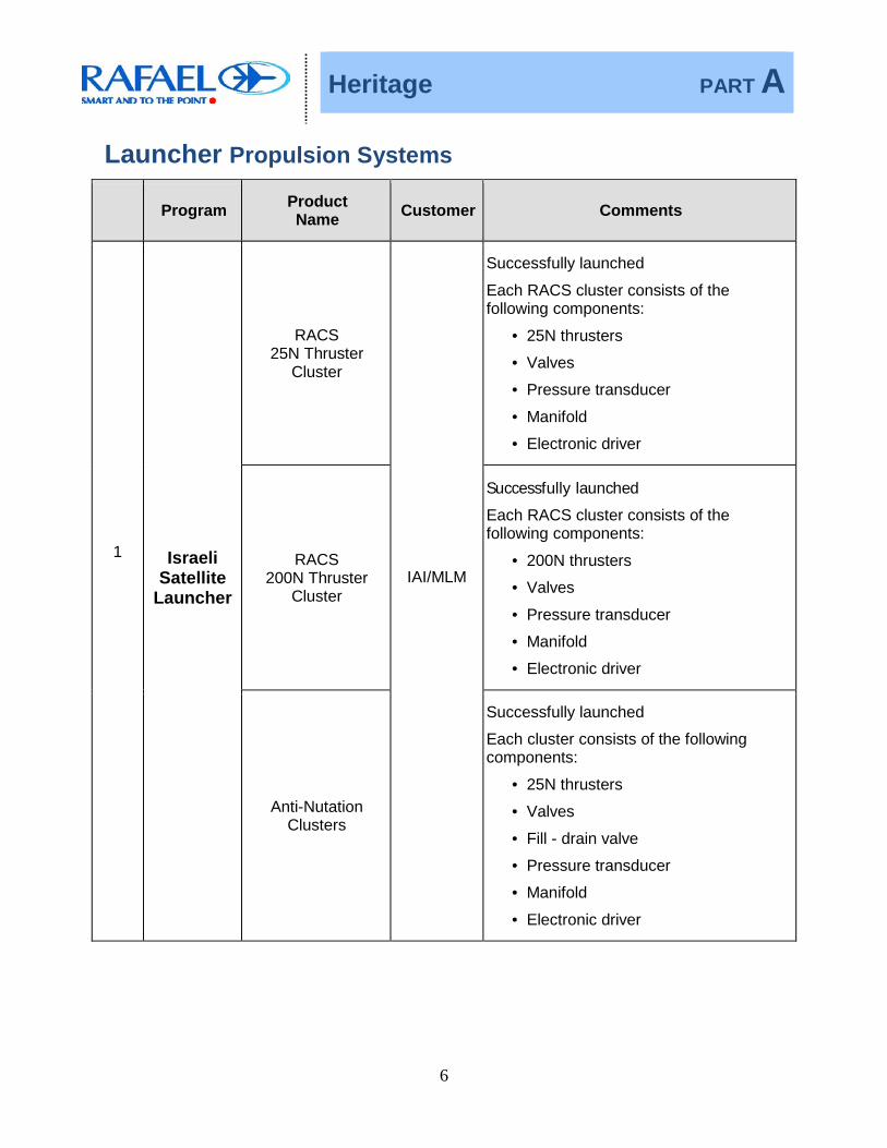
Launcher Propulsion Systems
Program Product Name Customer Comments
1 Israeli Satellite
Launcher
RACS 25N Thruster
Cluster
IAI/MLM
Successfully launched
Each RACS cluster consists of the following components:
• 25N thrusters
• Valves
• Pressure transducer
• Manifold
• Electronic driver
RACS 200N Thruster
Cluster
Successfully launched
Each RACS cluster consists of the following components:
• 200N thrusters
• Valves
• Pressure transducer
• Manifold
• Electronic driver
Anti-Nutation Clusters
Successfully launched
Each cluster consists of the following components:
• 25N thrusters
• Valves
• Fill - drain valve
• Pressure transducer
• Manifold
• Electronic driver
Heritage PART A
7
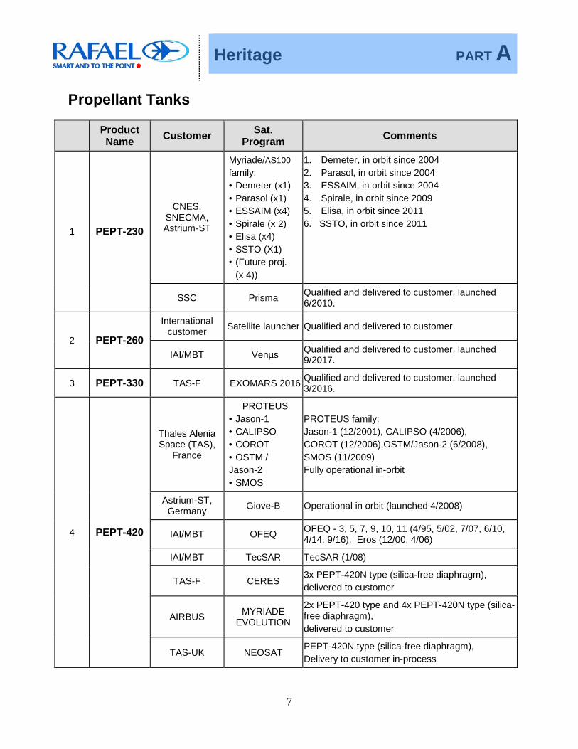
Propellant Tanks
Product Name Customer Sat.
Program Comments
1 PEPT-230
CNES, SNECMA, Astrium-ST
Myriade/AS100 family: • Demeter (x1) • Parasol (x1) • ESSAIM (x4) • Spirale (x 2) • Elisa (x4) • SSTO (X1) • (Future proj.
(x 4))
1. Demeter, in orbit since 2004 2. Parasol, in orbit since 2004 3. ESSAIM, in orbit since 2004 4. Spirale, in orbit since 2009 5. Elisa, in orbit since 2011 6. SSTO, in orbit since 2011
SSC Prisma Qualified and delivered to customer, launched 6/2010.
2 PEPT-260
International customer Satellite launcher Qualified and delivered to customer
IAI/MBT Venµs Qualified and delivered to customer, launched 9/2017.
3 PEPT-330 TAS-F EXOMARS 2016 Qualified and delivered to customer, launched 3/2016.
4 PEPT-420
Thales Alenia Space (TAS),
France
PROTEUS • Jason-1 • CALIPSO • COROT • OSTM / Jason-2 • SMOS
PROTEUS family: Jason-1 (12/2001), CALIPSO (4/2006), COROT (12/2006),OSTM/Jason-2 (6/2008), SMOS (11/2009) Fully operational in-orbit
Astrium-ST, Germany Giove-B Operational in orbit (launched 4/2008)
IAI/MBT OFEQ OFEQ - 3, 5, 7, 9, 10, 11 (4/95, 5/02, 7/07, 6/10, 4/14, 9/16), Eros (12/00, 4/06)
IAI/MBT TecSAR TecSAR (1/08)
TAS-F CERES 3x PEPT-420N type (silica-free diaphragm), delivered to customer
AIRBUS MYRIADE EVOLUTION
2x PEPT-420 type and 4x PEPT-420N type (silica-free diaphragm), delivered to customer
TAS-UK NEOSAT PEPT-420N type (silica-free diaphragm), Delivery to customer in-process

Heritage PART A
8
Product Name Customer Sat.
Program Comments
5 PEPT-590
Astrium-ST Galileo IOV (x5) Qualified and delivered to customer 2 tanks were launched (10/2011 and 10/2012)
TAS-F IXV Delivered to customer, launched (2/2015)
OHB-I PRISMA Delivered to customer
TAS-UK EXOMARS 2020 Delivered to customer (x2)
6 PEPT-590 GB
TAS-F Globalstar-2 Qualified and delivered to customer (x24),
launched between 2010 - 2013
O3B Qualified and delivered to customer (x20), 16 tanks were launched between 2013 - 2018
TAS-I Sentinel-1 ST1 A and B delivered to customer, launched 4/14 and 4/16, respectively ST1 C and D
TAS-I COSMO-SG Delivered to customer
7 GSU-1L NRL Slosh-Sat Operated in orbit (2/2005) 0.97 Liters (700 bar) – Cold Gas Tank
8 Xenon CNES/IAI Venµs Electric Propulsion Tank, Qualified and delivered to customer, launched 9/2017

Heritage PART A
9
Hydrazine Thrusters
Product Name Customer Sat. Program Quantities/Comments
1 1 N Thruster
Astrium-ST Galileo IOV 33 units operational in-orbit
TAS-F
Globalstar-2 96 units operational in-orbit
O3B 128 units (of 160) operational in-orbit
NEOSAT 40 units Delivery to customer in-process
TAS-I Sentinel-1 28 units operational in-orbit (ST1 A & B),
28 units (ST1 C & D)
COSMO-SG 12 units were delivered to customer
IAI Venµs 8 units operational in-orbit
OHB-I PRISMA 2 units delivered to customer
CONAE SAC-D 8 units delivered to customer
2 5 N Thrusters
IAI/MBT, Israel OFEQ EROS
TECSAR
More than 100 units were supplied Fully operational in-orbit
CONAE SAOCOM 44 units delivered to customer, part of Rafael Dual Thruster Module (DTM)
3 25 N Thrusters IAI/MBT, Israel
OFEQ EROS
TECSAR
More than 25 units were supplied Fully operational in-orbit
4 25N
RACS Thruster
IAI/MLM Israeli Satellite launcher
Qualified and delivered to customer
5 45N Thrusters
International customer
Satellite launcher Qualified and delivered to customer
6 200N RACS
Thrusters IAI/MLM Israeli Satellite
launcher Operational in-orbit

Heritage PART A
10
Propulsion System Valves
Product Name Customer Sat. Program Comments
1 Latch valves
IAI OFEQ EROS
TECSAR Operational in-orbit
International customer Satellite Qualified and delivered to customer
International customer GOKTURK-2 Operational in-orbit
OHB-I PRISMA Delivered to customer, part of Rafael HPS
2
FDV Fill and Drain valve
IAI OFEQ EROS
TECSAR Operational in orbit
International customer Satellite Qualified and delivered to customer
International customer GOKTURK-2 Operational in orbit
OHB-I PRISMA Delivered to customer (3-barriers FDV type), part of Rafael HPS
3
FVV Fill and Vent valve
IAI OFEQ EROS
TECSAR Operational in orbit
International customer Satellite Qualified and delivered to customer
International customer GOKTURK-2 Operational in orbit
OHB-I PRISMA Delivered to customer, part of Rafael HPS

Sat. Propulsion Systems PART B
11
Satellite Propulsion Systems
Hydrazine Cold Gas EPS - Electrical Propulsion System – Medium Power MEPS – Micro Electrical Propulsion System – Low Power

Sat. Propulsion Systems PART B
12
Hydrazine Propulsion System
Satellite Propulsion Systems
The Satellites Space Propulsion Systems are typically used for correction of orbit insertion errors and for orbit maintenance.
The monopropellant propulsion systems may typically use one of the following main architectural concepts:
Single branch propulsion, versus dual- branch (redundant) propulsion.
Low-thrust thrusters (5N or 1N), or high-thrust thrusters (25N).
Four thrusters, single-branch propulsion system architecture
Four thrusters, dual-branch (redundant) propulsion system architecture
Dual-Tank & dual branch propulsion (redundant) architecture with eight thrusters
Dual-branch (redundant) propulsion architecture with thrusters and PTs at branch-level

Sat. Propulsion Systems PART B
13
Hydrazine Propulsion System Architecture
The Propellant is loaded into the tank through a fill and drain valve (FDV). The pressurant gas is filled into the opposite side of the tank through a fill and vent valve (FVV). A flexible EPDM diaphragm separates between the propellant and the pressurant Inside the Tank. The tank maintains a gas pressure ratio of 4:1 (BOL/EOL). A pressure transducer installed on the propellant line enables monitoring the propellant pressure which indicates the residual propellant quantity during the mission. The latching valves (LV), provide an additional mechanical barrier for the hydrazine to meet the launch safety requirements and enables the option to disconnect the relative branch in case one of the thrusters fails throughout the mission. Once the latch valve is switched to OPEN, the pressurized propellant may be expelled towards the thrusters. Integral dual-seat dual-coil normally-closed flow control valves (FCV) control the propellant flow into the thrusters; thus the design satisfies the common three-barriers requirement. The pressure transducer is used throughout the service life of the satellite to estimate the residual hydrazine level; the pressure level is used by the control system as a parameter for estimating the available thrust. The system architecture is selected according to mission and reliability considerations. The use of redundant twin-branches propulsion significantly increases the system reliability. The system can include two types of thrusters, High Thrust (HT) or Low Thrust (LT), according to mission requirements. The thrust of the high thrust level thrusters may be chosen as 25N or 5N. The thrust level of the low thrust thruster may be chosen as 5N or 1 N. Differences between the chosen system architectures are derived from the mission and satellite requirements for reliability, lifetime, weight and number of thrusters. All Rafael propulsion systems and components flown have demonstrated 100% mission success, with no system or component failures or loss of redundancy.
Sat. Propulsion Systems PART B
14
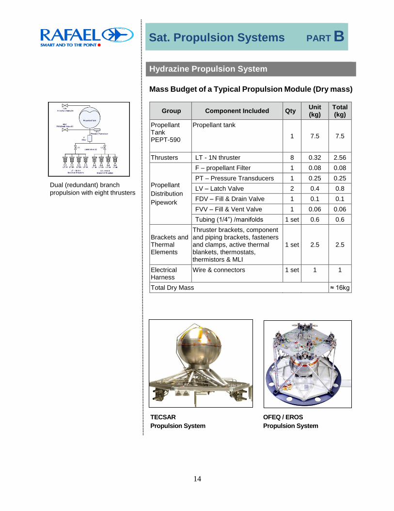
Hydrazine Propulsion System
Dual (redundant) branch propulsion with eight thrusters
Mass Budget of a Typical Propulsion Module (Dry mass)
Group Component Included Qty Unit (kg)
Total (kg)
Propellant Tank PEPT-590
Propellant tank 1 7.5 7.5
Thrusters LT - 1N thruster 8 0.32 2.56
Propellant Distribution Pipework
F – propellant Filter 1 0.08 0.08 PT – Pressure Transducers 1 0.25 0.25 LV – Latch Valve 2 0.4 0.8 FDV – Fill & Drain Valve 1 0.1 0.1 FVV – Fill & Vent Valve 1 0.06 0.06 Tubing (1/4”) /manifolds 1 set 0.6 0.6
Brackets and Thermal Elements
Thruster brackets, component and piping brackets, fasteners and clamps, active thermal blankets, thermostats, thermistors & MLI
1 set 2.5 2.5
Electrical Harness
Wire & connectors 1 set 1 1
Total Dry Mass ≈ 16kg
TECSAR OFEQ / EROS Propulsion System Propulsion System

Sat. Propulsion Systems PART B
15
Hydrazine Propulsion System
Design Considerations and ICD
During the design phase of the Propulsion System (PS) all the relevant considerations related to the satellite are taken into account, such as:
Mechanical interfaces and mass budget Electrical interfaces, power consumption and control
commands Thermal control, heat dissipation and radiation budget.
Mechanical Interfaces
The propulsion system components (e.g. tank, thrusters, LV, FDV/FVV, Manifolds, etc.) are installed on the satellite structure.
Two basic concepts of a PS components installation are available.
On a dedicated base plate Dispersed at various locations in the satellite.
In the case of using a dedicated base plate concept, the base plate itself may be supplied by Rafael, or by the Customer. The PS, together with the base plate, is installed as a plug-in module to the satellite.
The tank can be installed, held at the equator or poles, on the base plate or struts, subject to project requirements.
Plug-In Propulsion System

Sat. Propulsion Systems PART B
16
Hydrazine Propulsion System
Electric Interfaces
Rafael provides full electric interface for the Propulsion Systems. A typical PS electrical design includes the electrical harnesses which perform the link of command lines between the satellite and the active elements of the PS.
Electric wires, in accordance with space standards, are routed to on-board electrical devices. All splices, shrinks, crimps, lacing and soldering comply with ECSS-Q-70-08A.
Typical PS uses regulated (28±4 VDC typical) and unregulated voltage (25 to 45 VDC). The regulated voltage is supplied to the PS valves (FCV's, LV). The unregulated voltage may be used for the subsystem heaters.
Rafael performs overall electrical tests and provides a ready-to-connect plug-in module to the Satellite.
Thermal Control
Rafael is capable of delivering an all-around full thermal control solution as an integral part of the propulsion system.
Rafael's expertise is available for tanks as well as for thruster FCVs and for pipes; the capabilities include thermal analysis, thermal control design with redundancy options, specification of heating requirements, determining locations for heating elements (thermostats, thermistors) and use of thermocouples for heat measurement of thruster TCAs.
The heating controllers are governed by the satellite's main control unit.

Sat. Propulsion Systems PART B
17
Cold Gas Propulsion System
Rafael designs, develops and manufactures Cold Gas propulsion
systems.
Rafael was subcontracted by NLR to develop and manufacture the cold gas reaction controls system (RCS) for the Dutch SloshSat micro-satellite. The satellite was designed for ejection from a NASA Space Shuttle. SloshSat was launched on February 18, 2005, on board Ariane 5.
The Cold Gas RCS included 4 spherical carbon/epoxy- wrapped stainless steel tanks of a “leak-before-burst” design storing 1.6 kg
of gaseous Nitrogen propellant at 473 bars, corresponding to 20ºC. Each tank is equipped with an accessories assembly that includes a “self-seal” design pyro-valve and a filter. The cold-gas propellant is supplied to twelve 0.8N thrusters at a steady regulated pressure. Before reaching the thrusters, the gas passes through a surge damper, a two-stage pressure regulating assembly and a latch valve. For safety and redundancy, two relief valves are mounted downstream of the regulators. Thruster opening and closing response times are less than 5 ms. Delivery of a 70s specific impulse in vacuum was demonstrated.

Sat. Propulsion Systems PART B
18
Electric Propulsion System
Rafael designs, develops and manufactures Electric Propulsion Systems (EPS).
The Rafael EPS for the Venus satellite is designed to support and operate two IHET-300 Hall-Effect thrusters (HET), designed for low-power operation.
Venus EPS's main components are the 2 Hall-Effect Thrusters, Propellant Management Assembly (PMA), Digital Xenon Flow Controller (DXFC), Power Processing Unit (PPU), and 2 Filter Units (FU).
The PMA is composed of a tank, storing up to 16kg of high pressurized Xenon, and of a set of valves, pressure reducers and manifolds to transport the gas. The PPU comprises the power supplies and the sequencer command logic to operate the thrusters. The FU's function is to filter and to mitigate the thruster oscillations.
For missions requiring satellite thrust flexibility, a variable thrust mechanism is incorporated. The Rafael EPS incorporates a DXFC that serves as the "throttling" device for the xenon flow rate through the HET-300 anode.
The Rafael EPS for Venus can operate two thrusters, one at a time, as selected by the Thruster Selection Unit (TSU) according to mission requirements.

Sat. Propulsion Systems PART B
19
MEPS – Microsatellite Electric Propulsion System
MEPS Program
The MEPS system is an Electric Propulsion, based on Hall- Effect Thrusters, with performance levels in the range of 100 to 250W anodic power, which are suitable for typical microsatellites missions. Completion of the MEPS program development and qualification of an entire propulsion system is scheduled for the end of 2019. The goal is to qualify a Flight-Ready System, to be mature for integration into upcoming ESA and Israeli small and micro satellite missions Typical mission goals for MEPS are: Orbit keeping and drag compensation for LEO, down to
350 km altitudes. Controlling microsatellites in Formation-Flying missions. Accurate and precise final orbit insertion after
separation from launcher. Microsatellite Orbit transfer, either during mission, or at
lifetime disposal phase.
MEPS System Configuration
MEPS basic configuration consists of 5 major subsystems Two (x2) Hall-Effect Thruster Units (HETs) Power Processing Unit (PPU) Propellant Tank Assembly (PTA) Propellant Management Assembly (PMA) Fill and Vent Valve (FVV)

Sat. Propulsion Systems PART B
20
Thruster Unit
PTA (on S/C panel)
Data BUS
POWER BUS
PTA PMA
FVV
PPU
TU-A
TU-BPTA – Propellant Tank Assy.PMA – Propellant Management Assy.PPU – Power Processing UnitTU – Thruster UnitFVV – Fill & Vent Valve
PMA
The typical performance levels are a thrust of 6 through 14mN, and a total specific impulse of (Isp) of 780 through 1250 sec. Total MEPS dry mass (excluding brackets) is 15 kg and it can be easily accommodated onboard a typical small or micro satellite. Its designed lifetime is 7 years in LEO, with over 3000 operating hours per thruster.
PPU
FVV
MEPS is designed to be tolerant to single-point-of-failure by redundancy, excluding high-reliability parts such as the propellant tank. The philosophy behind the design of redundancy is to attain the maximal mission reliability, while saving space and volume at the same time. Since the propellant is Xenon, this is truly a "Green" and a safe propulsion system. MEPS components are shown on the left .
Electric Power LinesCommands & Control Lines Xenon Flow Lines

Propellant Tanks PART C
21
Propellant Tanks
Component
Tank Nominal Volume [Liter]
Qualified
Propellant Capacity [Liter]
Page No.
PEPT- 230 6 4.5 24
PEPT- 260 9.2 6.9 26
PEPT- 330 17.5 15.4 28
PEPT- 420 37.3 30 30
PEPT- 420N 37.5 30 32
PEPT- 590 102.5 75 34
PEPT- 590GB 204 154 36
GSU 1 L – Cold Gas 0.97 0.97 39
Xenon Tank 9.1 9.1 41
Note: The tanks can be partly filled in all configurations up to the full propellant capacity due to the use of a diaphragm as propellant management device.

Propellant Tanks PART C
22
Positive Expulsion Propellant Tank – General Description
Rafael’s Positive Expulsion Propellant Tank (PEPT) is made of 2 6Al-4V titanium alloy thin-walled hemispheres (optionally with a cylindrical mid-section extension). Positive fuel expulsion is provided by an EPDM-based rubber diaphragm retained between welded parts inside the tanks. Pressurant and propellant ports are weldable, 1/4” titanium tubes.
The Propellant Tank is made of the following segments:
• Lower hemisphere
• Upper hemisphere • Cylindrical extension section – optional • EPDM-based, silica-free rubber diaphragm
Integration to a complete tank is accomplished through peripheral Electron Beam Welding (EBW).
The hemispheres are hot-formed and machined to final dimensions. The design of the hemispheres enables the incorporation of integral pressurant and propellant ports.
The diaphragm has a 15 years life expectancy with hydrazine inside and has been qualified for various missions and satellite busses, such as Globalstar2, Myriade, Proteus, Galileo, Exomars, Neosat, OFEQ and others. The diaphragm has been qualified for use with ADN-based “green” propellant.

Propellant Tanks PART C
23
Diaphragm Propellant Management Device
The diaphragm allows active and efficient propellant management throughout the satellite’s lifetime. It allows multiple cycles of filling and emptying, simulation tests, as well as system integration and other tests.
In contrast to a surface tension-based propellant management device, a tank equipped with a diaphragm does not limit the degree of filling in any of the operational stages.
The tank may be partially filled to any degree, including prior to horizontal transportation on the launch pad, and the necessary gas-free propellant feed is assured for any subsequent demand. Another advantage is superior control over liquid sloshing.
This superior propellant management by diaphragm prevents undue sloshing loads which might adversely affect satellite stability during launch and maneuvers in space, as well as propellant feed which is made free of any limitations caused by satellite orientation, movement, or acceleration. Positive expulsion by the diaphragm prevents excessive center-of-gravity shift as caused by propellant movements in surface tension or bladder type tanks during satellite maneuvers, thus preventing excessive attitude-control system requirements.
Rafael's diaphragm material is silica free (no SiO2) enabling better performances of the PS thruster.

Propellant Tanks PART C
24
PEPT-230
PEPT-230
Propellant Tanks PART C
25
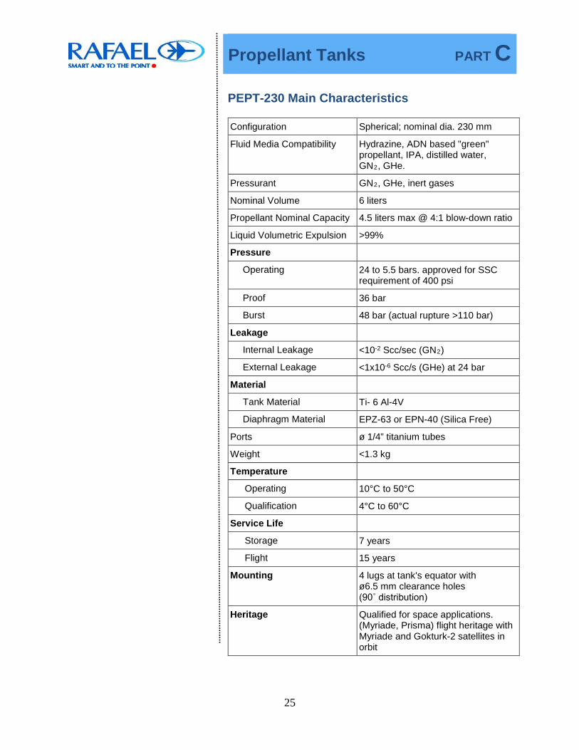
PEPT-230 Main Characteristics
Configuration Spherical; nominal dia. 230 mm
Fluid Media Compatibility Hydrazine, ADN based "green" propellant, IPA, distilled water, GN2, GHe.
Pressurant GN2, GHe, inert gases
Nominal Volume 6 liters
Propellant Nominal Capacity 4.5 liters max @ 4:1 blow-down ratio
Liquid Volumetric Expulsion >99%
Pressure
Operating 24 to 5.5 bars. approved for SSC requirement of 400 psi
Proof 36 bar
Burst 48 bar (actual rupture >110 bar)
Leakage
Internal Leakage <10-2 Scc/sec (GN2)
External Leakage <1x10⁻⁶ Scc/s (GHe) at 24 bar
Material
Tank Material Ti- 6 Al-4V
Diaphragm Material EPZ-63 or EPN-40 (Silica Free)
Ports ø 1/4” titanium tubes
Weight <1.3 kg
Temperature
Operating 10°C to 50°C
Qualification 4°C to 60°C
Service Life
Storage 7 years
Flight 15 years
Mounting 4 lugs at tank's equator with ø6.5 mm clearance holes (90˚ distribution)
Heritage Qualified for space applications. (Myriade, Prisma) flight heritage with Myriade and Gokturk-2 satellites in orbit

Propellant Tanks PART C
26
PEPT-260
PEPT-260

Propellant Tanks PART C
27
PEPT-260 Main Characteristics
Configuration Spherical, nominal dia. 260 mm Fluid Media Compatibility Hydrazine, IPA, distilled water, GN2, GHe. Pressurant GN2, GHe, inert gases Nominal Volume 9.2 liters Hydrazine Nominal Capacity 6.9 liters max @ 4:1 blow-down ratio Liquid Volumetric Expulsion > 99% Pressure
Operating 24 to 5.5 bar Proof 36 bar Burst 48 bar
Leakage Internal Leakage <1x10⁻² Scc/s (GN2) External Leakage <1x10⁻⁶ Scc/s (GHe) @ 24 bar
Material Tank Material Ti-6AI-4V Diaphragm Material EPN-40 (Silica Free)
Ports ø1/4” titanium tubes Weight <1.7 kg Temperature
Operating 10°C to 50°C Qualification 4°C to 60°C
Service Life Storage 7 years Flight 15 years
Mounting 4 lugs at tank's equator with ø6.5 mm clearance holes (90° distribution)
Heritage Qualified for space applications satellite Launcher (international), flight heritage with Venus satellite in orbit

Propellant Tanks PART C
28
PEPT-330
PEPT-330

Propellant Tanks PART C
29
PEPT-330 Main Characteristics
Configuration Spherical, nominal dia. 327 mm Fluid Media Compatibility Hydrazine, de-ionized water,
IPA, GN2, GHe
Pressurant GN2, GHe, inert gases Nominal Volume 17.5 liter Hydrazine Maximal Capacity 15.4 kg. Liquid Volumetric Expulsion ≥ 99.1% Pressure
Operating 29 bars (MEOP) Proof 36.25 bar Burst 43.5 bar
Leakage Internal Leakage <1x10⁻² Scc/s (GHe) External Leakage: <1x10⁻⁶ Scc/s (GHe)
Material Tank Material Ti-6AI-4V Diaphragm Material EPN-40 - Silica Free Tank tubes Ti3Al2.5V
Tubing Interface Pressuring tube: Ti-3Al-2.5V, 0.5" OD, 0.026" WT Propellant Tube: Ti-3Al-2.5V, 0.75" OD, 0.035" WT
Weight ≤ 3.1 kg Temperature
Operating (Qualification): +4°C to +50°C Non Operating (Qualification): -20°C to +60°C
Service Life Storage 7 years Flight 15 years
Mounting Pedestal mounting Heritage EXOMARS RCS DM
Propellant Tanks PART C
30
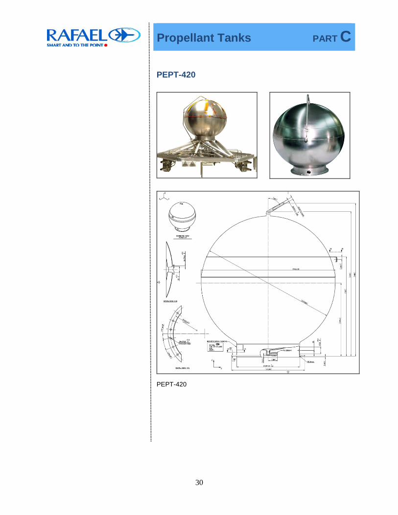
PEPT-420
PEPT-420

Propellant Tanks PART C
31
PEPT-420 Main Characteristics
Configuration Spherical, nominal dia. 420 mm Fluid Media Compatibility Hydrazine, distilled water, IPA,
GN2, GHe
Pressurant GN2, GHe Nominal Volume 37.3 liter Hydrazine Nominal Capacity 30 kg max.,
28 kg @ 4:1 blow-down ratio Liquid Volumetric Expulsion >98% Pressure
Operating 24 to 5.5 bar Proof 36 bar Burst 48 bar
Leakage Internal Leakage <1x10⁻² Scc/s (GHe) External Leakage <1x10⁻⁶ Scc/s (GHe)
Material Tank Material Ti-6AI-4V Diaphragm Material EPZ-63
Ports ø 1/4" weldable Ti tube or MS 33656-4 connections
Weight (kg) 3.6 Temperature
Operating (Qualification): 10°C to 50°C
Non Operating (Qualification): 4°C to 60°C
Service Life Storage 7 years
Flight 15 years
Mounting Pedestal mounting Heritage Flight heritage with OFEQ,
EROS, TecSAR and Proteus Programs, GIOVE-B/GSTB-V2 satellites in orbit

Propellant Tanks PART C
32
PEPT-420N
PEPT-420N
Propellant Tanks PART C
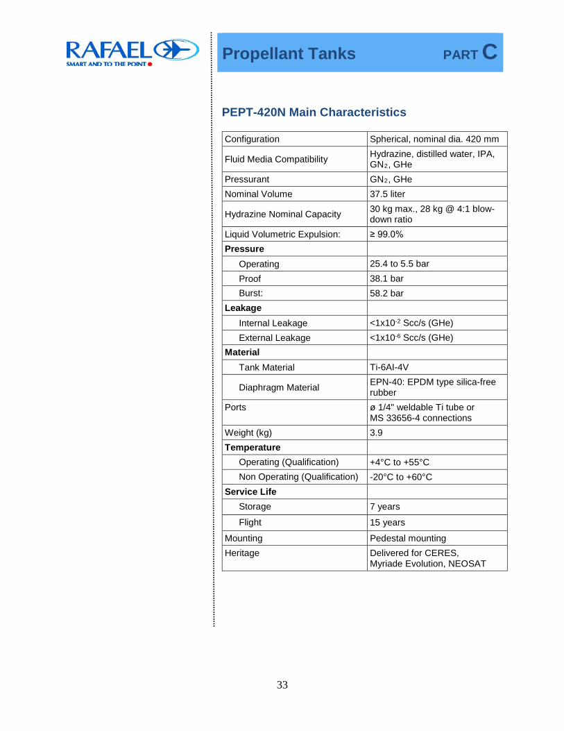
33
PEPT-420N Main Characteristics
Configuration Spherical, nominal dia. 420 mm
Fluid Media Compatibility Hydrazine, distilled water, IPA, GN2, GHe
Pressurant GN2, GHe Nominal Volume 37.5 liter
Hydrazine Nominal Capacity 30 kg max., 28 kg @ 4:1 blow-down ratio
Liquid Volumetric Expulsion: ≥ 99.0% Pressure
Operating 25.4 to 5.5 bar Proof 38.1 bar Burst: 58.2 bar
Leakage Internal Leakage <1x10⁻² Scc/s (GHe) External Leakage <1x10⁻⁶ Scc/s (GHe)
Material Tank Material Ti-6AI-4V
Diaphragm Material EPN-40: EPDM type silica-free rubber
Ports ø 1/4" weldable Ti tube or MS 33656-4 connections
Weight (kg) 3.9 Temperature
Operating (Qualification) +4°C to +55°C Non Operating (Qualification) -20°C to +60°C
Service Life Storage 7 years
Flight 15 years
Mounting Pedestal mounting Heritage Delivered for CERES,
Myriade Evolution, NEOSAT

Propellant Tanks PART C
34
PEPT-590
PEPT-590

Propellant Tanks PART C
35
PEPT-590 Main Characteristics
Configuration Spherical, 586 mm OD Fluid Media Compatibility Hydrazine, IPA, distilled water,
GN2, GHe Pressurant GN2, GHe Minimal Net Volume: 102.5 liter Propellant Nominal Capacity 75 kg Liquid Volumetric Expulsion > 99.1 % Pressure
Operating 24.6 to 5.5 bar
Proof 36.9 bar
Burst 49.2 bar
Leakage Internal Leakage <5.6x10⁻³ Scc/s (GHe)
External Leakage <1.0x10⁻⁶ Scc/s (GHe) at 24.6 bar
Material Tank Material Ti-6AI-4V
Diaphragm Material EPN-40: EPDM type silica-free rubber
Ports ø 1/4" tube weldable connections for both gas and hydrazine ports, made of Ti-6Al-4V
Weight 7.5 kg Temperature
Operating (Qualification) 4°C to 60°C
Non Operating (Qualification) -20°C to 60°C
Service Life Storage 7 years
Flight 15 years
Mounting Polar mounting Heritage Designed and qualified for
Galileo IOV, flight heritage with IXV, delivered for Exomars 2020, PRISMA
Propellant Tanks PART C
36
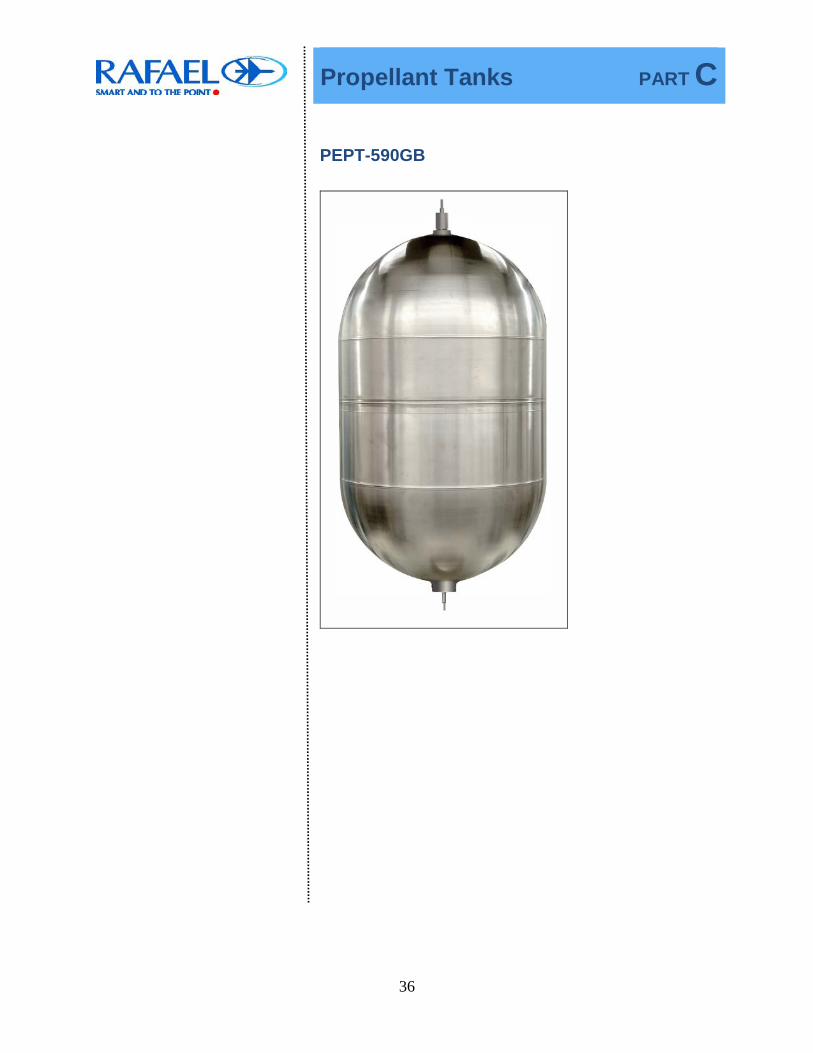
PEPT-590GB

Tanks PART C
37
PEPT-590GB

Tanks PART C
38
PEPT-590GB Main Characteristics
Configuration Cylindrically extended hemispheres, nominal dia. 587 mm x 1,170 mm length
Fluid Media Compatibility Hydrazine, IPA, distilled water, GN2, GHe
Pressurizing Media GN2, GHe Nominal Volume 204 liter Propellant Nominal Capacity 154 kg @ 4: 1 blow-down ratio Liquid Volumetric Expulsion > 99% Pressure
Operating 27.4 to 5.5 bar Proof 41.1 bar Burst 54.8 bar (actual rupture at 72 bar)
Leakage Internal Leakage <1x10⁻² Scc/s (GHe) External Leakage <1x10⁻⁶ Scc/s (GHe) at 27.4 bar
Material Tank Ti-6AI-4V Diaphragm EPN-40 (silica free)
Ports ø 1/4” weldable connections for both gas and hydrazine ports
Weight 17.5 kg Temperature
Operating (Qualification) 4°C to 50°C Non Operating (Qualification)
-20°C to 60°C
Service Life Storage 7 years Flight 15 years
Mounting Polar mounting Heritage Designed and qualified for
Globalstar-2, flight heritage with O3B and Sentinel-1 satellites in orbit, delivered for COSMO SG

Tanks PART C
39
GSU 1L Tank
GSU 1L - Main Characteristics
Configuration Nominal dia. 145 mm Nominal Volume 0.97 liter Pressure
Operating 700 bar Proof 1200 bar Burst 1900 bar
Material Shell Stainless steel or Ti 6AI 4V Composite Liner Carbon / epoxy
Weight Dry 1.3 kg Temperature - 40°C to 60°C Service Life Flight – 15 years Heritage NLR - Slosh Sat

Tanks PART C
40
Xenon Tank
Xenon Tank

Tanks PART C
41
Xenon Tank- Main Characteristics
Configuration Spherical, nominal dia. 270 mm Nominal Volume 9.1 liter Pressure
Operating 162 bar Proof 243 bar Burst 324 bar
Material Tank and manifold Ti 6AI 4V Interface tubes 1/8" SS 304L
Weight Dry 5.2 kg Qualification Temperature
Operating 5°C to 50°C Non-operating (empty) -25°C to 65°C
Mounting Polar mounting Heritage flight heritage with VENUS

Thrusters PART D
42
Thrusters
• Satellite Thrusters - Chapter D1
Component Rafael Name
Page No.
1N Thruster LT - 1N - SP 43 5N Thruster LT - 5N - SP 47 25N Thruster HT - 25N - SP 50 IHET 300W Thruster IHET 300 51
• Launcher Thrusters - Chapter D2
Component Rafael Name
Page No.
25N Thruster/Pitch Yaw Cluster AT - 25N 53 45N Thruster ACT - 45N 55 200N Class Thruster / Roll Cluster
ST - 200N 57
Satellite Thruster PART D1
43
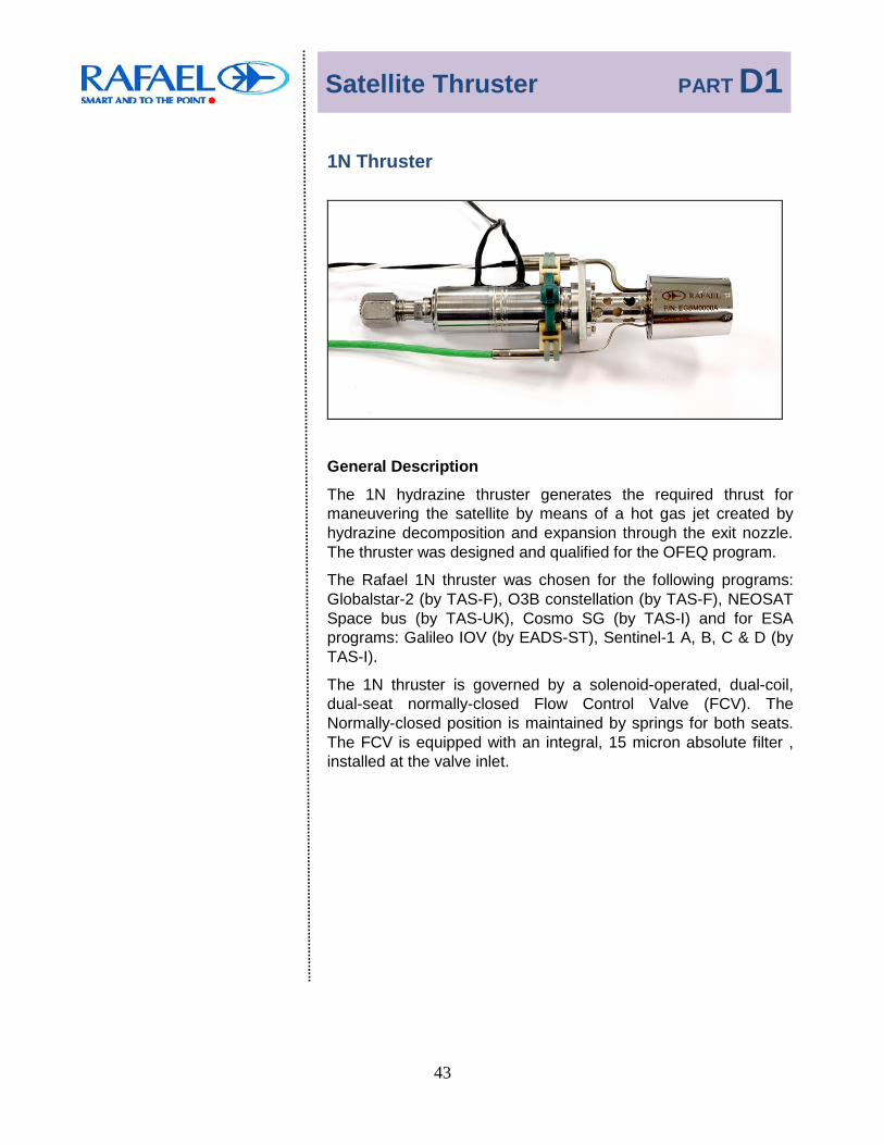
1N Thruster
General Description
The 1N hydrazine thruster generates the required thrust for maneuvering the satellite by means of a hot gas jet created by hydrazine decomposition and expansion through the exit nozzle. The thruster was designed and qualified for the OFEQ program.
The Rafael 1N thruster was chosen for the following programs: Globalstar-2 (by TAS-F), O3B constellation (by TAS-F), NEOSAT Space bus (by TAS-UK), Cosmo SG (by TAS-I) and for ESA programs: Galileo IOV (by EADS-ST), Sentinel-1 A, B, C & D (by TAS-I).
The 1N thruster is governed by a solenoid-operated, dual-coil, dual-seat normally-closed Flow Control Valve (FCV). The Normally-closed position is maintained by springs for both seats. The FCV is equipped with an integral, 15 micron absolute filter , installed at the valve inlet.

Satellite Thruster PART D1
44
1N Thruster

Satellite Thruster PART D1
45
The normally-closed FCV is operated by its solenoid, opened when energized and shut-off by electric switch-off. The valve is an all-welded construction.
The FCV consists of the following main parts: inlet port (filter included), valve body; coils (2); springs (2); seats (2); plungers (2) and a mounting flange.
The all-welded FCV and the Thrust Chamber Assembly (TCA) are assembled together through a perforated, Hayness-alloy tubular element, which serves as a thermal barrier between the TCA and the FCV. The thermal barrier controls heat conduction from the TCA to the FCV, throughout thruster operation and the heat soak-back period. A metallic seal provides the leak tightness between the FCV and the TCA.
The TCA incorporates a bell-shaped nozzle, with an expansion ratio of ε=130. It is welded to the decomposition chamber and
provides the required thrust.
The FCV has been developed and qualified by Rafael, as an integral part of its policy to develop an in-house capacity for components and processes .
The thruster is equipped with an electric catalyst bed heater (CBH), with two resistance coils, providing the initial thermal condition required for long duration and repeatable operation. The pre-heating time is required for reliable start of the thruster. The recommended pre-heating temperature is 180°C. The elapsed time to reach this temperature depends on the thruster's initial temperature. A typical time for pre-heating from +25°C is about 20 minutes.
Thruster inlet connection to the system tubing is through an MS 33656-4 threaded connector, complying with the requirement for a screwed connection. Alternatively, the thruster may be supplied with 1/4"or 3/8" welded inlet tube, according to customer preference.
There is no limitation on FCV heaters and thermistors bonding on free areas on the external envelope of the FCV.

Satellite Thruster PART D1
46
1N Thruster Main Characteristics
Parameter Characteristics
Propellant Hydrazine (N2H4)
Feed Pressure (bar abs) Type 1 Type 2
24.5 to 9 24.5 to 5.5
Thrust (BOL), Steady State (N) 1.3 ÷ 1.4 1.0 ÷ 1.1
Thrust (EOL), Steady State (N) > 0.2
SSF Specific Impulse (sec) >214 @ 22 bar
>205 @ 5.5 bar
Minimum Impulse Bit (N-s) 0.008 @ 5.5 bar and D/C 0.02 sec/1 sec
Nominal Duty Cycle 0.1 sec / 1 sec
Response Time (Hot Pulse)
Rise Time (ms) < 200 @ nominal duty cycle
Decay Time (ms) < 300 @ nominal duty cycle
Total Delivered Impulse (N-s) Type 1 Type 2
100,000 60,000
Total Number of Pulses Type 1 Type 2
100,000 58,000
Leakage
Internal Leakage (Scc/s GHe): < 1.0x10⁻⁵ @ 5.5 bar and 24.5
External Leakage (Scc/s GHe): < 1.0x10⁻⁶ @ 24.5
Temperature Operating: +5°C to 90°C Non Operating: -10°C to 95°C
Flow Control FCV – dual-coil, dual seat, NC solenoid valve
FCV Operating Voltage (Vdc) 23 to 36
FCV Power (W) 9.2 @ 28 Vdc
Heater – Dual Element
Heater Operating Voltage (Vdc) 23 to 36
Heater Resistance (ohms) 257 for each element
Nozzle Expansion Ratio 130
Total Life (Storage and Flight) 15 years
Inlet Filtration 15 micron absolute
Inlet Interface MS 33656-4 or welded tube (1/4" or 3/8")
Weight (gr.) ≤ 310 (1000 mm lead wire length)
Heritage Qualified for OFEK, Globalstar-2, O3B and GALILEO IOV. Flight heritage with Globalstar-2, O3B, Venus, GALILEO -IOV, Sentinel-1 and Gokturk PS2. Delivered for COSMO SG, Neosat SB and PRISMA.

Satellite Thruster PART D1
47
5 N Thruster
5N Thruster

Satellites Thruster PART D1
48
5 N Thruster Main Characteristics
Parameter Characteristics Propellant Hydrazine (N2H4)
Feed Pressure (bar abs) 24 to 5.5 (nominal), tested down to 4.5
Thrust, Steady State (N) 6.1 @ 22 bar to 1.8 @ 5.5 bar
SSF Specific Impulse (sec) >220 @ 22 bar
>210 @ 5.5 bar
Minimum Impulse Bit (N-s) <0.25 @ 5.5 bar & 0.1 sec / 1 sec <0.012 @ 5.5 bar & 0.06 sec / 1000 sec
Nominal Duty Cycle 0.1 sec / 1 sec
Response Time (Hot Pulse)
Rise Time(ms) < 65 @ nominal duty cycle & 22 bar
Decay Time (ms) <100 @ nominal duty cycle & 22 bar
Total Delivered Impulse (N-s) 74,000
Total Number of Pulses 42,000 Leakage
Internal Leakage (Scc/s GHe) <1.0x10⁻⁴ @ 3.5 and 24 bar
External Leakage (Scc/s GHe) <2.6x10⁻⁴ @ 24 bar Temperature
Operating Temperature +4°C to 90°C
Non Operating Temperature -10°C to 90°C Flow Control FCV - single-coil, dual-seat, NC solenoid
valve
FCV Operating Voltage (Vdc) 23 to 36
FCV Power (W) 9.2 @ 28 Vdc
Heaters - 3× Single Heaters
Heater Operating Voltage (VDC)
24 to 32
Heater Resistance (ohms) 260 per each heater
Nozzle Expansion Ratio 50
Total Life (Storage and Flight) 15 years
Inlet Filtration 15 micron absolute
Inlet Interface MS 33656-4 or welded tube (1/4" or 3/8")
Weight (gr.) ≤ 310 (2000 mm lead wires length)
Heritage OFEQ, EROS and TECSAR programs Delivered to SAOCOM

Satellites Thruster PART D1
49
25 N Thruster
25N Thruster

Satellites Thruster PART D1
50
25 N Thruster Main Characteristics
Parameter Characteristics Propellant Hydrazine (N2H4) Feed Pressure (bar abs.) 22 to 5.5 Thrust, Steady State (N) 28 to 9.5 SSF Specific Impulse (sec) > 220 @ 22 bar
> 205 @ 5.5 bar Minimum Impulse Bit (N-s) 0.3 Nominal Duty Cycle 0.24 sec / 1 sec Response Time (Hot Pulse)
Rise Time (ms) 65 @ nominal duty cycle & 22 bar Decay Time (ms) 200 @ nominal duty cycle & 22 bar
Total Delivered Impulse (N-s ) 100,000 (<5%Isp degradation) Total Number of Pulses: 12,000 Leakage
Internal Leakage (Scc/s GHe): <1.0x10⁻⁴ @ 3.5 & 24 External Leakage (Scc/s GHe): <1.0x10⁻⁶ @ 24
Temperature Operating Temperature +4°C to 90°C Non Operating Temperature -10°C to 90°C
Flow Control FCV - single-coil, dual-seat, NC solenoid valve
FCV Operating Voltage (Vdc) 23 to 36 FCV Power (W) 15 @ 28 Vdc
Heaters – 4× Single Heaters
Heater Operating Voltage (Vdc) 24 to 32 Heater Resistance (ohms) 260 per each heater
Nozzle Expansion Ratio 60 Total Life (Storage & Flight) 15 years Inlet Filtration 15 micron absolute
Inlet Interface MS 33656-4 or welded tube (1/4" or 3/8") Weight (gr.) ≤ 530 (1000 mm lead wires length) Heritage OFEQ and EROS programs

Satellites Thruster PART D1
51
IHET300 Thruster
The heart of the Electrical Propulsion System (EPS) is the Israeli Hall-Effect Thruster (IHET), code named IHET-300. It operates on Xenon, which is ionized by electrons emitted from the cathode and accelerated as plasma using a high electric field.
This thruster is ideal for use onboard small and micro satellites, operating nominally on a mere 300W anode power. However, its useful range of operation is between 250 to 600W. Thus, it may utilize the instantaneous available power from the satellite.
IHET-300 Main Characteristics Characteristics Parameter
Thrust (@300W) > 15 mN Specific impulse (@ 300W) > 1300 sec Nominal anodic power 300W Power operation range 250W to 600W Operating life > 1000 hours Number of operations > 2000 Mass 1.6 kg Dimensions 170x120x90 mm Heritage Space proven - Venus Program
Thruster during Test Firing in
Firing chamber Thruster installed in Firing chamber

Launcher Thruster PART D2
52
Thrusters
Launcher Thrusters

Launcher Thruster PART D2
53
25N Thruster
25N Thruster integrated in the Roll Attitude control system
(RACS) cluster including valves, pressure transducer and electronic driver
25 N Thruster

Launcher Thruster PART D2
54
25N Thruster Main Characteristics
Characteristics Parameter Propellant Hydrazine (N2H4) Feed Pressure (bar abs.) 26.2 Thrust, Steady State (N) 24
SSF Specific Impulse (sec) >220 @ 24 bar >210 @ 6 bar
Minimum Impulse Bit (N-s) 1.5 Weight (gr.) 310 Heritage Israeli satellite launcher

Launcher Thruster PART D2
55
45N Thruster
45 N Thruster

Launcher Thruster PART D2
56
45N Thruster Main Characteristics
Propellant Hydrazine (N2H4) Feed Pressure (bar abs.) 24 to 6 Thrust, Steady State (N) 45 to 16 SSF Specific Impulse (sec) >208 @ 24 bar
>190 @ 6 bar Total Impulse (N-s) SSF 60,000 PMF 15,000
Impulse Bit (N-s) 5.3 @ 24 bar & 100 msec. ON 2.3 @ 6 bar & 100 msec. ON
Response Time (Hot Pulse)
Rise Time (ms) Decay Time (ms)
100 @ 24 bar 200 @ 24 bar
Leakage External Leakage (Scc/s GHe) <1 x 10⁻⁴ @ 3.5 & 24 bar External Leakage (Scc/s GHe) <2.7 x 10⁻⁴ @ 24 bar Flow Control FCV - single-coil, single-seat,
N.C. solenoid valve FCV Operating Voltage (Vdc) 24 - 32 FCV Power (Watt) 17@ 28 VDV & 20°C Inlet Filtration 15 microns absolute Inlet Interface MS 33656-4 Nozzle Expansion Ratio 50 Weight (gr.) 500 (500 mm lead wires length) Heritage Space Qualified
Launcher Thruster PART D2
57
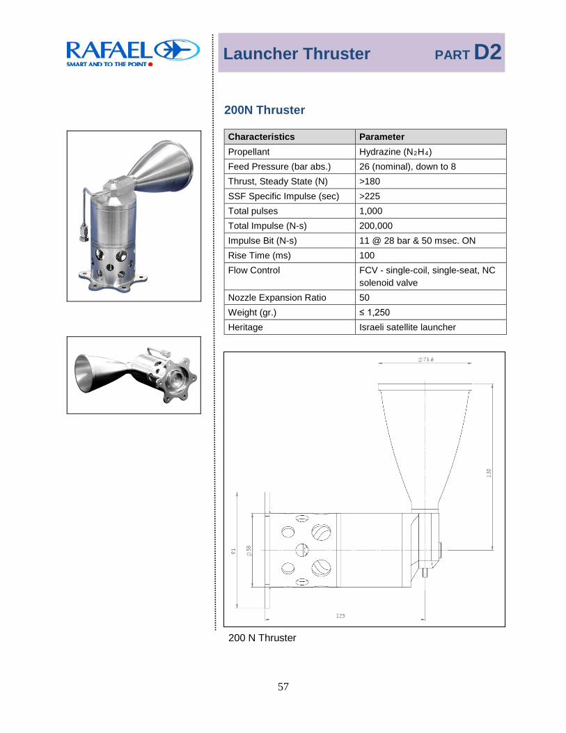
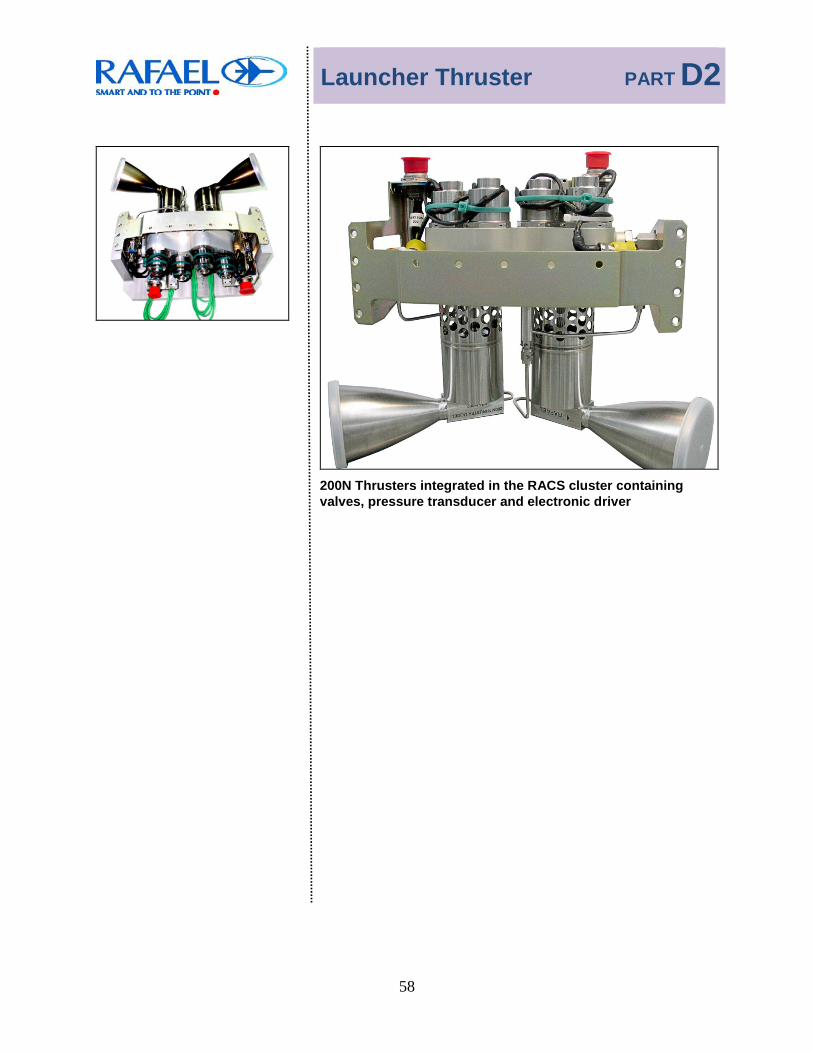
200N Thruster
Characteristics Parameter Propellant Hydrazine (N2H4) Feed Pressure (bar abs.) 26 (nominal), down to 8 Thrust, Steady State (N) >180 SSF Specific Impulse (sec) >225 Total pulses 1,000 Total Impulse (N-s) 200,000 Impulse Bit (N-s) 11 @ 28 bar & 50 msec. ON Rise Time (ms) 100 Flow Control FCV - single-coil, single-seat, NC
solenoid valve Nozzle Expansion Ratio 50 Weight (gr.) ≤ 1,250 Heritage Israeli satellite launcher
200 N Thruster
Launcher Thruster PART D2
58
200N Thrusters integrated in the RACS cluster containing
valves, pressure transducer and electronic driver

Propulsion System Valves PART E
59
Propulsion System Valves
Component Description Page No.
FDV Fill and Drain Valve 60
FVV Fill and Vent Valve 61
LV Latch Valve 62
SMAV Shape Memory Alloy Valve 64
Propulsion System Valves PART E
60
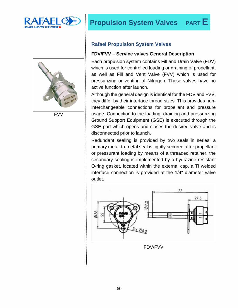
Rafael Propulsion System Valves FDV/FVV – Service valves General Description
FVV
Each propulsion system contains Fill and Drain Valve (FDV) which is used for controlled loading or draining of propellant, as well as Fill and Vent Valve (FVV) which is used for pressurizing or venting of Nitrogen. These valves have no active function after launch. Although the general design is identical for the FDV and FVV, they differ by their interface thread sizes. This provides non-interchangeable connections for propellant and pressure usage. Connection to the loading, draining and pressurizing Ground Support Equipment (GSE) is executed through the GSE part which opens and closes the desired valve and is disconnected prior to launch. Redundant sealing is provided by two seals in series; a primary metal-to-metal seal is tightly secured after propellant or pressurant loading by means of a threaded retainer, the secondary sealing is implemented by a hydrazine resistant O-ring gasket, located within the external cap, a Ti welded interface connection is provided at the 1/4" diameter valve outlet.
FDV/FVV
Propulsion System Valves PART E
61
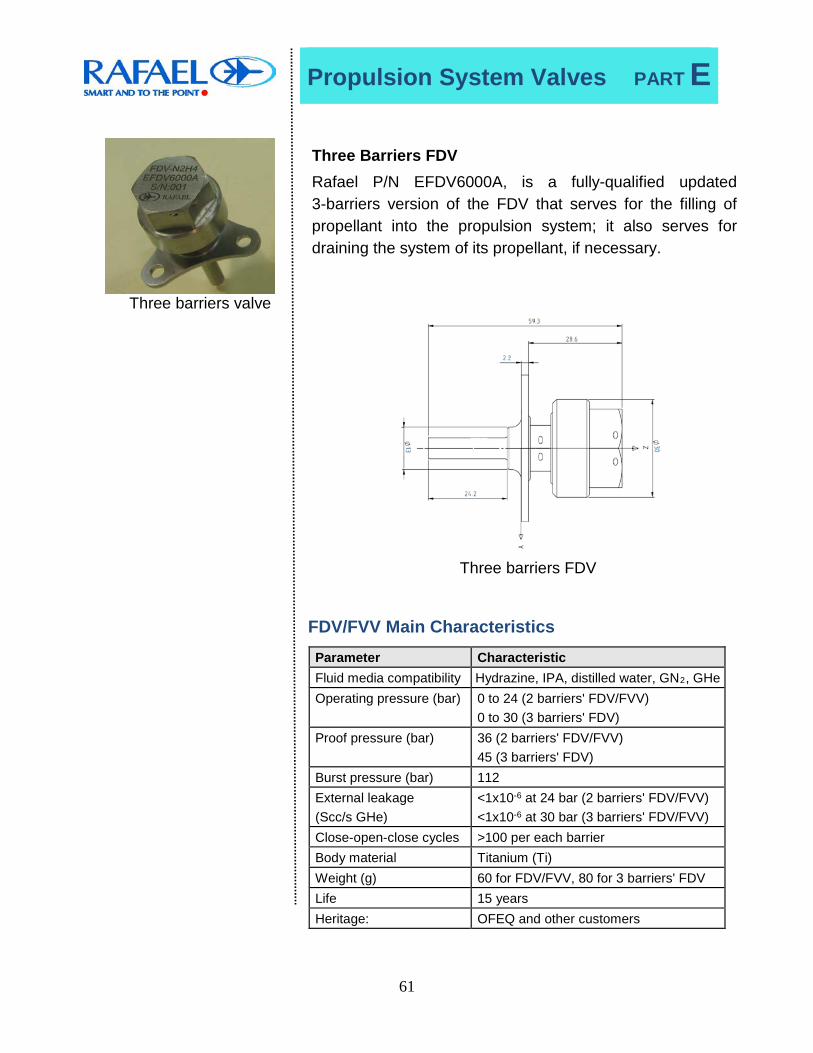
Three barriers valve
Three Barriers FDV Rafael P/N EFDV6000A, is a fully-qualified updated 3-barriers version of the FDV that serves for the filling of propellant into the propulsion system; it also serves for draining the system of its propellant, if necessary.
Three barriers FDV
FDV/FVV Main Characteristics
Parameter Characteristic Fluid media compatibility Hydrazine, IPA, distilled water, GN2, GHe Operating pressure (bar) 0 to 24 (2 barriers' FDV/FVV)
0 to 30 (3 barriers' FDV) Proof pressure (bar) 36 (2 barriers' FDV/FVV)
45 (3 barriers' FDV) Burst pressure (bar) 112 External leakage (Scc/s GHe)
<1x10⁻⁶ at 24 bar (2 barriers' FDV/FVV) <1x10⁻⁶ at 30 bar (3 barriers' FDV/FVV)
Close-open-close cycles >100 per each barrier Body material Titanium (Ti) Weight (g) 60 for FDV/FVV, 80 for 3 barriers' FDV Life 15 years Heritage: OFEQ and other customers

Propulsion System Valves PART E
62
Latch Valve
LV General Description The solenoid operated latching valve (LV) is dual-coil, single-
seat magnetically latched. A momentary electric input signal is required to change the position of the plunger; the appropriate coil is pulse-energized, and switches the plunger from OPEN to CLOSED position, or vice-versa.
Once the LV has changed its position, a permanent magnet provides the magnetic latching force necessary to maintain it in its last selected position, and no further energizing is required.
The valve employs a 15-micron absolute integrated filter.
The LV is equipped with a reed-switch (magnetic type), which operates as a limit switch (connect/disconnect capability), providing an indication of the valve position.
Latch Valve

Propulsion System Valves PART E
63
LV Main Characteristics Parameter Characteristic Data Valve Type Magnetic latching, solenoid
operated Fluid Media Compatibility Hydrazine, IPA, distilled water,
GN2, GHe Pressure Operating (bar) 0 to 24 Proof (bar) 36 Burst (bar) 96 Pressure Drop (bar) <1 @ 20 gr/sec hydrazine Back Pressure Relief <14 bar Electrical Operating Voltage (Vdc) 24 to 32 Power (W) 25 @ 28 Vdc for each coil Operating Response Time (ms) < 50 @ 28 Vdc and 24 bar Pull In Voltage (Vdc) < 20 @ 24 bar
Insulation Resistance (MΩ) 100 @ 100 Vdc
Dielectric Resistance (MA) 2 @ 500 Vac & 50/60 Hz Leakage Internal Leakage Scc/s (GHe) <1 x10⁻⁴ @ 3.5 and 22 bar External Leakage Scc/s (GHe) <1 x10⁻⁶ @ 36 bar Temperature Operating Temperature +5°C to 80°C Non-Operating Temperature -10°C to 90°C Life Storage 7 years Flight 8 years Cycle >20,000 Built-In Position Indication Magnetic position sensor Built-In Filter: 15 microns abs. Inlet & Outlet Interface: MS 33656G-4 or 0.25" tubes Weight (gr.) < 370 Heritage OFEQ and other foreign
customers

Propulsion System Valves PART E
64
Shape Memory Alloy Valve - SMAV
SMAV General Description Shape Memory Alloy Valve (SMAV) is an inert solution for one-
shot device based on smart materials. SMA is well known for
its chemical and physical durability. The actuator, including the
heater, in this valve may be pulled out and tested before final
integration in the application. Single-core heater is the default,
and dual-core heater is available for redundancy.
Thermocouple is optional. Hence, this valve has superior
reliability. SMAV is a hermetic device since the inlet is sealed
with a nipple which is sheared by the SMA actuator. The SMA
actuator is sealed with a bellow. SMAV exhibits excellent
internal and external leakage. Inlet and outlet tubes are 1/4"
Titanium.
SMA Valve

Propulsion System Valves PART E
65
SMAV Main Characteristics Parameter Characteristic Data Valve Type SMA operated Fluid Media Compatibility Hydrazine, N2O4, De-Ionized
Water, IPA, GNR2R, GHe, Argon
Pressure and Mass Flow Operating (bar) 0 to 25 Proof (bar) 38 Burst (bar) 100 Pressure Drop (bar) 0.15 @ max pressure Flow (gr/s) 83 Hydrazine @ 11bar Electrical Operating Voltage (Vdc) 24 to 32 Power (Watt) 30W per core @ 24 Vdc Operating Response Time (sec) <30 @ 24 Vdc & 25 bar
Insulation Resistance (MΩ) 100Mohm with 100 Vdc
Dielectric Resistance (mA) 2 @ 500 Vac & 50/60 Hz Leakage Internal Leakage Scc/s (GHe) <1 x10⁻⁷ @ 3.5 and 22 bar External Leakage Scc/s (GHe) <1 x10⁻⁹ @ 36 bar Temperature Operating Temperature +5°C to 50°C Non-Operating Temperature -20°C to 70°C Life Storage 5 years Flight 15 years Cycle 1 Built-In temperature measurement
Optional thermocouple
Inlet & Outlet Interface MS 33656G-4 or 0.25" tubes Weight (gr.) 100
Production Capabilities PART F
66
Space Production Capabilities

Production Capabilities PART F
67
Clean Rooms
Components and subsystem assembly and integration are carried out in special clean room facilities, complying with US Federal Std. 209B, ranging from Class 100,000 to Class 100.
Parts, components and subassemblies are cleaned to the highest levels using special equipment (ultra-sonic, flushing
benches) and checked for level of cleanliness using computerized particle counters (gas and liquid) and UV light. Hydraulic and pneumatic flow benches, equipped with special tools for flow control adjustment, flow
calibration and hydraulic response time measurements, have been installed in the clean room.
Orbital welding is used for tubing manifolds manufacturing and propulsion system integration in the clean room.
A new clean room, completed in 2010, houses the propulsion modules production including the components production.
The new clean room includes assembly, integration and testing (AIT) sections from the components' level through the sub-assemblies level and four stations of propulsion system AIT.
Rafael 1,000 m² Clean Room Site

Production Capabilities PART F
68
Hydrazine Thruster Test Firing
Hydrazine thrusters hot-firing tests are carried out at Rafael facilities, which include open air test stands as well as four vacuum chambers delivering 10-3 torr. One of these includes a spin table for functional tests under actual spin conditions. In these facilities thruster activation, data acquisition, reduction and analysis are highly automated and remotely operated using video and computer equipment & techniques. Methods have been developed to cater for special requirements, such as accurate measurement of thrust and impulse, ranging from high to very low values (corresponding to a wide range of duty-cycles), thermal measurements and flow visualization in vacuum of transparent thruster exhaust gases by RF glow discharge effect, etc.
Vacuum/Spin Test Facility
Vacuum chambers for space simulation at Rafael Test Firing Facility
Production Capabilities PART F
69
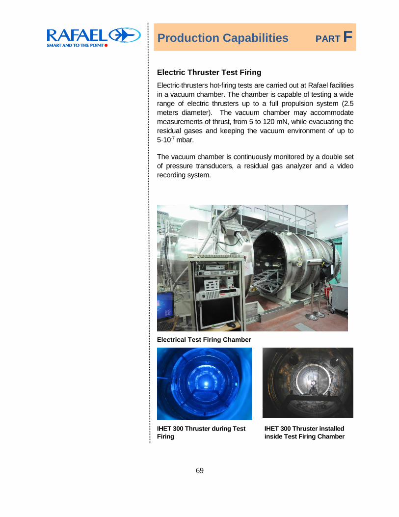
Electric Thruster Test Firing Electric thrusters hot-firing tests are carried out at Rafael facilities
in a vacuum chamber. The chamber is capable of testing a wide range of electric thrusters up to a full propulsion system (2.5 meters diameter). The vacuum chamber may accommodate measurements of thrust, from 5 to 120 mN, while evacuating the residual gases and keeping the vacuum environment of up to 5·10-7 mbar.
The vacuum chamber is continuously monitored by a double set of pressure transducers, a residual gas analyzer and a video recording system.
Electrical Test Firing Chamber
IHET 300 Thruster during Test Firing
IHET 300 Thruster installed inside Test Firing Chamber

Production Capabilities PART F
70
Testing and Inspection Facilities
The Rafael test and inspection facilities include a wide range of environmental tests (all aspects of dynamic, climatic, thermal, and vacuum) as well as metallurgical, chemical and dimensional inspection and analytic laboratories.
A wide range of non-destructive capabilities, such as X-ray, dye penetrant inspection, ultra-sonic are available for development, qualification, production and acceptance tests.
Automatic CMM Dimensional Inspection
Propellant Tank mounted on
shaker for Vibration Testing X-ray Device

Production Capabilities PART F
71
Diaphragm Material Roll Mill
Manufacturing
A wide range of highly qualified manufacturing facilities are available to meet space standards and requirements. These include CAD/CAM; CNC machining; electro-erosion; forming; hydro-spinning and deep hot- and cold-drawing; surface treatment; heat treatment; welding (including EBW, GTAW, GMAW, plasma); brazing; cutting, bending and faring of
titanium tubes; rubber and composite materials manufacture.
Rafael's capabilities are complemented by using the existing facilities at SOREQ Nuclear Research Center, for testing of components at various radiation levels and their proof of operation in space conditions.
Press Shear Spinning Device
Surface Treatment Facility Electron Beam Welding
5 Axes CNC Center Electron Beam Welding
Production Capabilities PART F
72
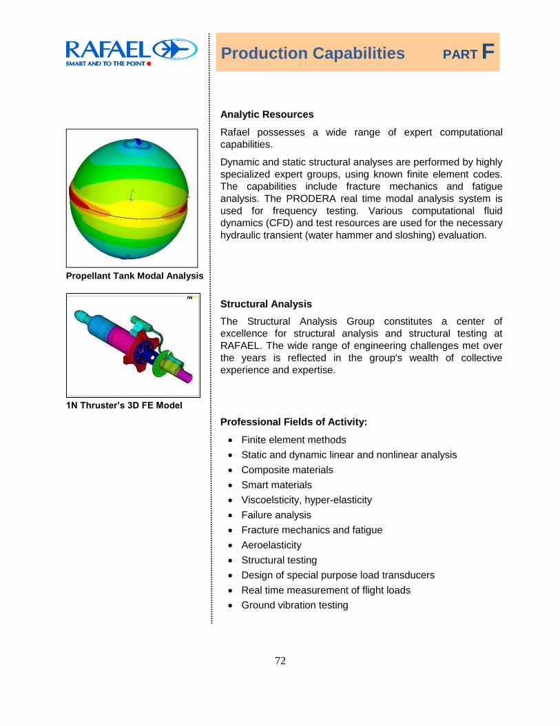
Propellant Tank Modal Analysis
Analytic Resources
Rafael possesses a wide range of expert computational capabilities.
Dynamic and static structural analyses are performed by highly specialized expert groups, using known finite element codes. The capabilities include fracture mechanics and fatigue analysis. The PRODERA real time modal analysis system is used for frequency testing. Various computational fluid dynamics (CFD) and test resources are used for the necessary hydraulic transient (water hammer and sloshing) evaluation.
1N Thruster’s 3D FE Model
Structural Analysis The Structural Analysis Group constitutes a center of excellence for structural analysis and structural testing at RAFAEL. The wide range of engineering challenges met over the years is reflected in the group's wealth of collective experience and expertise.
Professional Fields of Activity:
Finite element methods Static and dynamic linear and nonlinear analysis Composite materials Smart materials Viscoelsticity, hyper-elasticity Failure analysis Fracture mechanics and fatigue Aeroelasticity Structural testing Design of special purpose load transducers Real time measurement of flight loads Ground vibration testing

Production Capabilities PART F
73
Mechanical Design Tools
1N Thruster Model View
3-D CAD software, such as SolidWorks™ is used for layout design of the PS. The CAD models are used for thermal, structural and mass properties analysis.
1N Thruster Thermal Analysis
Heat and Mass Transfer Analysis The Heat and Mass Transfer Analysis Group is responsible for the thermal design and analysis of most of Rafael's products. It is the largest thermal design group in Israel. The group activity covers all aspects of thermal design required for the aerospace and military industry including: thermal and fluid flow analysis, development and implementation of thermal solutions, and experimental validation (laboratory and field experiments). The group uses various commercial and in-house codes for simulations including SINDA/G, PATRAN, SINDARAD and FLUENT. The group also developed codes and subroutines for heat transfer, thermal signature, ablation and aero-heating simulations. The group's heat transfer laboratory is capable of conducting experimental validation of thermal analysis using a variety of experimental setups to simulate conduction, convection and radiation processes through measurement of temperatures (contact and non-contact methods), heat fluxes and thermal properties (conductivity, diffusivity, specific heat and emissivity using standard and self-developed techniques).

Production Capabilities PART F
74
Ground Support Equipment
Ground support equipment (GSE) is used for testing components and systems. A dedicated alignment method assists in the alignment of thrusters in the systems. Propellant, pressurant and test fluid loading, unloading and vacuum leak checks are accomplished by general and custom-made benches and trolleys, all developed and fabricated by Rafael. Leak checks of components, subassemblies and complete systems are carried out using helium mass-spectrometers, and internal dryness is assured using a sensitive hygrometer.
The varied fields of expertise at our disposal enable us to benefit from the wide base of Rafael’s infrastructure and at the same time take advantage of the specific hydrazine propulsion technology developed during years of experience.
GSE Propulsion Systems Electrical Tester A dedicated computerized tester on Rafael premises is used to carry out electrical tests of integrated propulsion systems. The tester automatically conducts tests, such as:
Response time of the thrusters
Heaters' resistance
Calibration of pressure transducers
Threshold voltage for actuation of valves
The tester provides a report which includes all test results and the respective requirements.

Production Capabilities PART F
75
Propellant Loading – Launch Campaigns
Rafael has worldwide expertise and heritage in propellant loading of Satellites and Launchers. This includes Israel, Russia, French Guiana and India.

Quality Management PART G
76
Quality Management

Quality Management PART G
77
Quality Management
Rafael places major emphasis on the high quality of its products.
Rafael maintains an extensive Quality System, which aims to provide its customers with high-quality products. The system is integrated into all Rafael's divisions and activities, and is applied during the entire life cycle of our projects. Rafael's Quality System is described in detail in Rafael's Quality Manual.
Rafael Quality system is certified by NQA to AS 9100:2009.
Rafael is certified by the International Certification Network (EQNet) to ISO 9001: 2008 and to ISO 14001. Rafael's Safety Organization is certified to the OHSAS 18001.
The Rafael Quality System is documented in a comprehensive procedures system which complies with the above mentioned international/national standards requirements.
Quality Management PART G
78
Quality Management Organization
For each R&D or production program, a Quality Manager is assigned.
The Quality Manager has the authority and responsibility to instruct, conduct and integrate the quality plan in all activities and groups involved in the program phases.
The Quality Manager is the point of contact to the Customer for all Quality activities.
The main activities that are co-coordinated or monitored by the project Quality Manager are:
• Representing the Customer in the Quality activities performed in RAFAEL.
• PA Plan preparation, implementation and control.
• DRB performance for products prior to and at delivery to customer.
• Quality audits results evaluation and initiation of Corrective Action Plans.
• Failure Report and Corrective Action System (FRACAS) activities and reports.
• Member of Engineering Change Board.
• Chairman of Nonconformance Review Board.
• Secretary of Corrective Action Board.
• Review of Contract Quality requirements.

Quality Management PART G
79
Certificate for Welding by Nadcap
Certificate for Non Destructive Testing by Nadcap

UNC.28503-1009/m5/02 Graphic design Dep/406
Rafael Space Systems Tel. (972)733353306 Fax: (972)7333352135 email: [email protected]