Embed Size (px)
Citation preview

RADview-EMS/NGN Element Management System for NGN
Applications
ACE-3600
© 1994–2008 RAD Data Communications Publication 05/08


RADview-EMS/NGN ACE-3600 i
Contents
Chapter 1. Introduction
1.1 ACE-3600 Overview .................................................................................................... 1-1 1.2 Product Options ......................................................................................................... 1-1
Chassis Options ...................................................................................................... 1-1 Main Module (Main Card) Options ........................................................................... 1-2 Interface Module Options ........................................................................................ 1-2 Power Options ........................................................................................................ 1-2 License Packs .......................................................................................................... 1-3
1.3 RADview-EMS/NGN ACE-3600 Overview ...................................................................... 1-3 Configuration Operations ........................................................................................ 1-3
Device-Level Configuration ................................................................................. 1-3 Port-Level Configuration ..................................................................................... 1-5 Application-Level Configuration .......................................................................... 1-5
Performance Monitoring Operations ........................................................................ 1-7 Device-Level Performance Monitoring ................................................................. 1-7 Port-Level Performance Monitoring .................................................................... 1-7 Application-Level Performance Monitoring .......................................................... 1-8
Fault Detection Operations ..................................................................................... 1-9 Device-Level Fault Detection .............................................................................. 1-9 Port-Level Fault Detection ................................................................................ 1-10
Chapter 2. Installation and Operation
2.1 Pre-Configuring for Network Management .................................................................. 2-1 2.2 Connecting to the Management Station ..................................................................... 2-1
Using an Out-of-Band LAN Connection .................................................................... 2-1 Using an Inband ATM VC Connection ....................................................................... 2-2 Using an IP-Based or Inband PW Connection ............................................................ 2-2
2.3 Launching RADview ACE-3600 .................................................................................... 2-3 2.4 Using the Graphical User Interface (GUI) ..................................................................... 2-5
Using the Device Level Interface .............................................................................. 2-5 Using the Port Level Interface ................................................................................. 2-6 On-Screen LED Indicators ........................................................................................ 2-7
Chapter 3. Configuration Management
3.1 Setting the System Parameters .................................................................................. 3-2 Entering System Information ................................................................................... 3-2 Setting the Date and Time ...................................................................................... 3-4
Changing the Date ............................................................................................. 3-6 Validating the Date and Time .............................................................................. 3-7 Setting the Summer Time Parameters ................................................................. 3-7
Setting the Syslog Parameters .............................................................................. 3-11 Defining Managers ................................................................................................ 3-12
Adding Managers ............................................................................................. 3-14 Removing Managers ......................................................................................... 3-16 Masking Traps .................................................................................................. 3-16
Setting the OV Severity ......................................................................................... 3-22 Configuring Access to Web and Telnet ................................................................... 3-22
3.2 Setting the Operational Parameters .......................................................................... 3-24
Table of Contents User's Manual
ii RADview-EMS/NGN ACE-3600
Configuring Ports .................................................................................................. 3-24 Configuring the Ethernet Port ........................................................................... 3-24 Configuring the Gigabit Ethernet Ports .............................................................. 3-26 Configuring the ATM-155 Ports ........................................................................ 3-28
Setting the Protection Parameters ........................................................................ 3-33 Setting the Main Module Redundancy ............................................................... 3-34 Setting the Ethernet Redundancy ..................................................................... 3-36 Setting Automatic Protection Switching (APS) ................................................... 3-39
Defining the Clock Source ..................................................................................... 3-45 Configuring Traffic Descriptors .............................................................................. 3-47
Adding Traffic Descriptors ................................................................................ 3-50 Modifying Traffic Descriptors ............................................................................ 3-52 Removing a Traffic Descriptor ........................................................................... 3-53 Traffic Descriptor Validation ............................................................................. 3-53
Configuring OAM ................................................................................................... 3-53 Configuring OAM Loopback Parameters ............................................................ 3-53 Configuring OAM Descriptors ............................................................................ 3-54
Configuring the ATM Cross-Connect (XC) Parameters ............................................. 3-58 Adding ATM Cross Connections ......................................................................... 3-60 XC Validation .................................................................................................... 3-63 Changing an ATM Cross Connection Parameter ................................................. 3-63 Removing ATM Cross-Connections .................................................................... 3-64 Searching for an XC .......................................................................................... 3-64
Configuring the Router.......................................................................................... 3-64 Configuring the Router Parameters ................................................................... 3-65 Configuring the Router Interface ...................................................................... 3-66 Setting the Static Route Parameters ................................................................. 3-72
Configuring MPLS Parameters ................................................................................ 3-75 Setting the Label Range ................................................................................... 3-76 Configuring the LDP ......................................................................................... 3-77 Configuring the Tunnel LSP Parameters ............................................................. 3-84
Configuring Multiservice over PSN Parameters ....................................................... 3-89 Configuring General Multiservice over PSN Parameters ...................................... 3-90 Defining PSN Peers ........................................................................................... 3-91 Configuring Pseudowire Connections ................................................................ 3-94
3.3 Additional Tasks ..................................................................................................... 3-117 Polling the Hardware ........................................................................................... 3-117 Resetting the Hardware ...................................................................................... 3-118 Restoring the Default System Configuration ........................................................ 3-118 Viewing and Swapping Software Files .................................................................. 3-119 Saving/Deleting the Default Configuration File ..................................................... 3-120 Downloading Software via a TFTP Server ............................................................. 3-121 Downloading a Preset Configuration via a TFTP Server ......................................... 3-126
Chapter 4. Configuring a Typical Application
4.1 3G Services over PSN ................................................................................................. 4-1 4.2 Configuring the ACE-3600 Unit ................................................................................... 4-2
Configuring the Physical Layer Parameters .............................................................. 4-3 Configuring the ATM-155 Ports .......................................................................... 4-3 Configuring the GbE Ports .................................................................................. 4-5 Configuring the Ethernet Port ............................................................................. 4-6
Setting the Protection Parameters .......................................................................... 4-7 Setting System Redundancy ............................................................................... 4-7
User's Manual Table of Contents
RADview-EMS/NGN ACE-3600 iii
Setting Ethernet Redundancy ............................................................................. 4-8 Setting ATM-155 Port Protection ...................................................................... 4-10
Configuring the Router Parameters ....................................................................... 4-12 Configuring the Traffic Descriptors ........................................................................ 4-15 Configuring the Multiservice over PSN Parameters ................................................. 4-17 Configuring the Remote Peer Parameters .............................................................. 4-18 Configuring the Pseudowire Parameters ................................................................ 4-19
Configuring Pseudowire General Parameters ..................................................... 4-20 Configuring Pseudowire PSN Parameters ........................................................... 4-21 Configuring Pseudowire Service Parameters ...................................................... 4-22 Configuring ATM Attachment Circuit Parameters ............................................... 4-24
Setting the Clock Source ....................................................................................... 4-30
Chapter 5. Performance Management
5.1 Introduction ............................................................................................................... 5-1 Statistical Tables and Graphs................................................................................... 5-1 Graph Characteristics .............................................................................................. 5-2
Vertical Axis Scale ............................................................................................... 5-2 Horizontal Axis ................................................................................................... 5-2 Interval Date and Time ....................................................................................... 5-3 Number of Displayed Polls .................................................................................. 5-3 Customizing the Appearance of Graph Lines ....................................................... 5-3 Numerical Value Tooltip ...................................................................................... 5-4
Setting the Polling Interval ...................................................................................... 5-4 5.2 Viewing APS Statistics ................................................................................................ 5-6
Viewing the APS Running Statistics ........................................................................ 5-10 Closing the APS Statistics Table ............................................................................. 5-11 Refreshing the APS Statistics Table ....................................................................... 5-11
5.3 Viewing ATM XC Statistics ......................................................................................... 5-12 Viewing VC User Statistics ..................................................................................... 5-13
Viewing VC User Current Statistics .................................................................... 5-13 Viewing VC User Intervals Statistics ................................................................... 5-16
Viewing VC OAM Statistics ..................................................................................... 5-18 Viewing VC OAM Current Statistics .................................................................... 5-18 Viewing VC OAM Intervals Statistics .................................................................. 5-20
Viewing VC OAM Loopback Statistics ..................................................................... 5-22 Viewing VC OAM Loopback Current Statistics .................................................... 5-22 Viewing VC OAM Loopback Intervals Statistics ................................................... 5-24
5.4 Viewing the ATM-155 Port Physical Layer Statistics ................................................... 5-26 Viewing the ATM-155 Port Physical Layer Current Statistics ................................... 5-26 Viewing the ATM-155 Port Physical Layer Intervals Statistics .................................. 5-28
5.5 Viewing the ATM-155 Port Logical Layer Statistics .................................................... 5-29 Viewing the ATM Layer Current Statistics ............................................................... 5-29 Viewing the ATM Layer Intervals Statistics ............................................................. 5-32
5.6 Monitoring the Gigabit Ethernet (GbE) Ports ............................................................. 5-34 Viewing the GbE Port Information ......................................................................... 5-34 Viewing the GbE Port Statistics ............................................................................. 5-36
Viewing the GbE Current Statistics in the Rx Direction ....................................... 5-36 Viewing the GbE Current Statistics in the Tx Direction ....................................... 5-38 Viewing the GbE Intervals Statistics in the Rx Direction ..................................... 5-39 Viewing the GbE Intervals Statistics in the Tx Direction ...................................... 5-41
5.7 Monitoring the Ethernet Port ................................................................................... 5-42 5.8 Monitoring Multiservice over PSN Traffic ................................................................... 5-44
Table of Contents User's Manual
iv RADview-EMS/NGN ACE-3600
Viewing the Pseudowire Connection Status ........................................................... 5-44 Viewing the Pseudowire Connection Statistics ....................................................... 5-47
Displaying the Statistics from a Specific PW ...................................................... 5-49 Viewing the Pseudowire Current Cells Statistics ................................................ 5-50 Viewing the Pseudowire Current Packets Statistics ............................................ 5-52 Viewing the Pseudowire Intervals Cells Statistics ............................................... 5-54 Viewing the Pseudowire Intervals Packets Statistics .......................................... 5-56 Closing the PW Statistics Table ......................................................................... 5-58 Refreshing the PW Statistics Table .................................................................... 5-59
Viewing all Attachment Circuits ............................................................................. 5-59 5.9 Monitoring LDP ........................................................................................................ 5-60
Viewing the LDP Label Statistics ............................................................................ 5-61 Viewing the Statistics of a Single Label ............................................................. 5-62
Viewing the LDP Hello Message Statistics .............................................................. 5-64 Viewing the LDP Session Statistics ........................................................................ 5-66
5.10 Viewing the Installed License Status ......................................................................... 5-67 5.11 Viewing the Syslog Statistics .................................................................................... 5-69
Chapter 6. Security Management
6.1 Adding Users.............................................................................................................. 6-1 6.2 Changing Usernames .................................................................................................. 6-1 6.3 Changing Passwords .................................................................................................. 6-2 6.4 Setting Management Access Authorization ................................................................. 6-2
Using the EMS Security Console .............................................................................. 6-2 Setting a Security Profile ......................................................................................... 6-3 Setting Permissions ................................................................................................ 6-4
6.5 Enabling SNMPv3........................................................................................................ 6-5
Chapter 7. Fault Management
7.1 Monitoring Object Status ............................................................................................ 7-1 Interpreting the Map Icon Colors ............................................................................. 7-1 Viewing the Active Alarms ....................................................................................... 7-2
Filtering the All Active Alarm List ......................................................................... 7-4 Printing the All Active Alarm List ......................................................................... 7-5 Saving the All Active Alarm List ........................................................................... 7-5 Closing the All Active Alarm List .......................................................................... 7-5 Refreshing the All Active Alarm List .................................................................... 7-5
Viewing the History Log .......................................................................................... 7-5 Printing the History Log ...................................................................................... 7-7 Saving the History Log ....................................................................................... 7-7 Viewing the Next Page of the History Log ........................................................... 7-8 Viewing the History Log from a Specific Entry ..................................................... 7-8 Closing the History Log ...................................................................................... 7-8 Refreshing the History Log ................................................................................. 7-8
Clearing the History Log .......................................................................................... 7-8 7.2 Performing Diagnostic Tests ....................................................................................... 7-9
Viewing the Self Test Results .................................................................................. 7-9 Setting the Loopback Timeout .............................................................................. 7-11 Viewing and Performing Diagnostics on an ATM-155 Port ...................................... 7-12 Performing a Cell Test ........................................................................................... 7-14
7.3 Troubleshooting ....................................................................................................... 7-16 Checking the On-Screen LEDs................................................................................ 7-16

User's Manual Table of Contents
RADview-EMS/NGN ACE-3600 v
Corrective Measures .............................................................................................. 7-16 7.4 Frequently Asked Questions ..................................................................................... 7-17 7.5 Technical Support .................................................................................................... 7-19
Index

Table of Contents User's Manual
vi RADview-EMS/NGN ACE-3600

RADview-EMS/NGN ACE-3600 Product Options 1-1
Chapter 1
Introduction This introductory chapter includes:
• ACE-3600 Overview
• Product Options
• RADview-EMS/NGN ACE-3600 Overview.
1.1 ACE-3600 Overview
ACE-3600 is an advanced carrier-class gateway, optimized for transporting 3G voice and HSDPA data traffic over next-generation core PSNs (packet-switched networks), including Layer-2, MPLS, or IP. Its modular physical architecture, hardware redundancy features, and aggregation abilities, make ACE-3600 a customizable, fail-safe, and high-end traffic concentrator for third-generation cellular operators and carriers.
Typically located at the 3G RNC site, ACE-3600 interconnects with the RNC and converts up to four simultaneous fiber optic STM-1/OC-3c (ATM-155) links into virtual pseudowire (PW) connections that are established over a packet-switched network, using the unit's Gigabit Ethernet interface.
1.2 Product Options
The following product options are described in this section:
• Chassis Options
• Main Module (Main Card) Options
• Interface Module Options
• Power Options
• License Packs
Chassis Options
The ACE-3600 chassis is 2U high and fully modular.
The chassis has a passive backplane that includes pin connectors with which the main modules and interface modules engage. The chassis supports the following modules:
Chapter 1 Introduction User's Manual
1-2 Product Options RADview-EMS/NGN ACE-3600
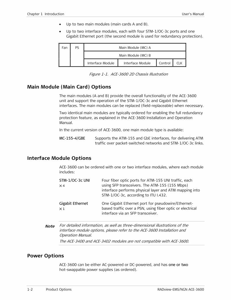
• Up to two main modules (main cards A and B).
• Up to two interface modules, each with four STM-1/OC-3c ports and one Gigabit Ethernet port (the second module is used for redundancy protection).
Fan PS Main Module (MC) A
Main Module (MC) B
Interface Module Interface Module Control CLK
Figure 1-1. ACE-3600 2D Chassis Illustration
Main Module (Main Card) Options
The main modules (A and B) provide the overall functionality of the ACE-3600 unit and support the operation of the STM-1/OC-3c and Gigabit Ethernet interfaces. The main modules can be replaced (field-replaceable) when necessary.
Two identical main modules are typically ordered for enabling the full redundancy protection feature, as explained in the ACE-3600 Installation and Operation Manual.
In the current version of ACE-3600, one main module type is available:
MC-155-4/GBE Supports the ATM-155 and GbE interfaces, for delivering ATM traffic over packet-switched networks and STM-1/OC-3c links.
Interface Module Options
ACE-3600 can be ordered with one or two interface modules, where each module includes:
STM-1/OC-3c UNI 4
Four fiber optic ports for ATM-155 UNI traffic, each using SFP transceivers. The ATM-155 (155 Mbps) interface performs physical layer and ATM mapping into STM-1/OC-3c, according to ITU I.432.
Gigabit Ethernet 1
One Gigabit Ethernet port for pseudowire/Ethernet-based traffic over a PSN, using fiber optic or electrical interface via an SFP transceiver.
For detailed information, as well as three-dimensional illustrations of the interface module options, please refer to the ACE-3600 Installation and Operation Manual.
The ACE-3400 and ACE-3402 modules are not compatible with ACE-3600.
Power Options
ACE-3600 can be either AC-powered or DC-powered, and has one or two hot-swappable power supplies (as ordered).
Note
User's Manual Chapter 1 Introduction
RADview-EMS/NGN ACE-3600 RADview-EMS/NGN ACE-3600 Overview 1-3
License Packs
The available software license pack is:
LDP Enables the label distribution protocol (LDP) functionality.
1.3 RADview-EMS/NGN ACE-3600 Overview
'RADview-EMS/NGN ACE-3600' is comprehensive, GUI-based management software for monitoring and controlling ACE-3600. The RADview solution conforms to the ITU-T Telecommunication Management Network (TMN) recommendations for SNMP management systems, known as the FCAPS management model:
• Fault management – Detects and correlates faults in network devices, isolates faults, and initiates recovery actions.
• Configuration management –
Tracks configuration changes.
Configures, installs, and distributes software and configuration files across the network.
Enables viewing and modifying the configuration of the system, ports, and alarms.
Enables viewing the diagnostics and status information.
• Accounting management – Collects accounting data and generates network usage reports.
• Performance management – Continuously monitors network performance (QoS, CoS) and resource allocation.
• Security management – Controls and restricts access to network resources.
Configuration Operations
Configuration operations can be performed at the following levels:
• System (see Device-Level Configuration)
• Port (see Port-Level Configuration)
• Application (see Application-Level Configuration)
Device-Level Configuration
System level configuration operations are available when the device image is selected in the main window.
The following table summarizes the different configuration options at the system level.

Chapter 1 Introduction User's Manual
1-4 RADview-EMS/NGN ACE-3600 Overview RADview-EMS/NGN ACE-3600
Table 1-1. System-Level Configuration Options
Task Relevant Dialog Box RADview Path
Polling the hardware None Configuration
System Commands
Poll Agent
Restoring the default
system configuration
Default Configuration Configuration
System Commands
Default Configuration
Resetting the hardware Reset Configuration Configuration
System Commands
Reset
Viewing and swapping
software files
SW Files Configuration
System Commands
SW Files
Saving/Deleting the
default configuration file
Save Active Configuration Configuration
System Commands
Save Active
Configuration as a
Default File
Configuring system
information
System Information Configuration
System Info
Configuring date and time Date & Time Configuration
Date & Time
Configuring source clock Source Clock Configuration
Clock
Source
Configuring main card
redundancy
Main Card Redundancy Configuration
Protection
Main Card
Redundancy
Configuring Ethernet
redundancy
Ethernet Redundancy Table Configuration
Protection
Ethernet Redundancy
Configuring APS APS Table Configuration
Protection
APS
Configuring Syslog server
parameters
Syslog Configuration
Syslog
Viewing management
locations
Manager List Options
Manager List
Configuring OV severity OV Severity Options
OV Severity

User's Manual Chapter 1 Introduction
RADview-EMS/NGN ACE-3600 RADview-EMS/NGN ACE-3600 Overview 1-5
Task Relevant Dialog Box RADview Path
Configuring access to
Web and Telnet status
Access Options
Access
Port-Level Configuration
Port level configuration operations are available when a port is selected in the main window.
The same RADview path can open different dialog boxes, depending on the selected port.
The following table summarizes the different configuration options at the port level.
Table 1-2. Port-Level Configuration Options
Task Relevant Dialog Box RADview Path
Configuring GbE port
parameters
Port Parameters Configuration
Parameters
Configuring Ethernet port
parameters
Port Parameters Configuration
Parameters
Configuring ATM-155
SONET/SDH layer
Port Parameters Configuration
Parameters
Configuring ATM-155 ATM
layer
Port Parameters Configuration
Parameters
Configuring OAM Cell
Generation
Port Parameters Configuration
Parameters
Application-Level Configuration
Application level configuration consists of configuring the application parameters, which include the ATM, router, MPLS, Multiservice over PSN and PSN functionality categories.
The application parameters are configured according to the nature of the specific application in which ACE-3600 is used.
Table 1-3. Application-Level Configuration Options
Task Relevant Dialog Box RADview Path
Configuring ATM
parameters
ATM Parameters Table Configuration
ATM
Parameters
Configuring ATM traffic
descriptors
ATM Traffic Descriptor Table Configuration
ATM
Traffic Descriptor
Note

Chapter 1 Introduction User's Manual
1-6 RADview-EMS/NGN ACE-3600 Overview RADview-EMS/NGN ACE-3600
Task Relevant Dialog Box RADview Path
Configuring ATM OAM
parameters
OAM Parameters Configuration
ATM
OAM Parameters
Configuring ATM OAM
descriptors
ATM OAM Descriptor Table Configuration
ATM
OAM Descriptor
Configuring ATM cross
connections (XC)
ATM Cross Connection Table Configuration
ATM
XC ATM
Configuring router
parameters
Router Parameters Configuration
Router
Parameters
Configuring router
interfaces
Router Interfaces Table Configuration
Router
Interface
Configuring static route
parameters
Routing Table Configuration
Router
Routing
Configuring MPLS
parameters
MPLS Parameters Configuration
MPLS
Parameters
Configuring MPLS LDP
parameters
LDP Parameters Configuration
MPLS
LDP Parameters
Configuring MPLS LDP
interface
LDP Interface Table Configuration
MPLS
LDP Interface
Configuring MPLS LDP
targeted peers
LDP Targeted Peer Table Configuration
MPLS
LDP Targeted Peer
Configuring MPLS ingress
LSP tunnels
Ingress LSP Tunnel Table Configuration
MPLS
Tunnel LSP Ingress
Configuring MPLS egress
LSP tunnels
Egress LSP Tunnel Table Configuration
MPLS
Tunnel LSP Egress
Configuring Multiservice
over PSN general ATM
parameters
Multiservice over PSN ATM
Parameters
Configuration
Multiservice over PSN
General ATM

User's Manual Chapter 1 Introduction
RADview-EMS/NGN ACE-3600 RADview-EMS/NGN ACE-3600 Overview 1-7
Task Relevant Dialog Box RADview Path
Configuring Multiservice
over PSN peers
Peer Table Configuration
Multiservice over PSN
Peer
Configuring Multiservice
over PSN pseudowires
(PWs)
Pseudowire Table Configuration
Multiservice over PSN
PW
Performance Monitoring Operations
Performance monitoring operations can be performed at the system, port and application level.
Device-Level Performance Monitoring
System level performance operations are available when the device image is selected in the main window.
The following table summarizes the different configuration options at the system level.
Table 1-4. System-Level Performance Monitoring Options
Task Relevant Dialog Box RADview Path
Setting polling interval Polling Interval Statistics
Polling Interval
Viewing APS table APS Statistics Statistics
Protection APS
Viewing Syslog statistcs Syslog Statistics Statistics
Syslog
Viewing License Status License Status Table Options
License Status
Port-Level Performance Monitoring
Port level performance operations are available when the port is selected in the main window.
The same RADview path can open different dialog boxes, depending on the selected port.
The following table summarizes the different performance options at the port level.
Note

Chapter 1 Introduction User's Manual
1-8 RADview-EMS/NGN ACE-3600 Overview RADview-EMS/NGN ACE-3600
Table 1-5. Port-Level Performance Monitoring Options
Task Relevant Dialog Box RADview Path
Viewing the GbE port
status
Port Status Configuration
Port Status
Viewing the Ethernet
port status
Port Status Configuration
Port Status
Viewing the ATM-155
physical layer
(SDH/SONET) current
statistics
Port Current Statistics Statistics
Current
Viewing the ATM-155
physical layer
(SDH/SONET) interval
statistics
Port Intervals Statistics Statistics
Intervals
Viewing the ATM-155
logical layer (ATM)
current statistics
Interface Current Statistics Statistics
Current
Viewing the ATM-155
logical layer (ATM)
intervals statistics
Interface Intervals Statistics Statistics
Intervals
Viewing the GbE current
Rx statistics
Port Current Rx Statistics Statistics
Current Rx
Viewing the GbE current
Tx statistics
Port Current Tx Statistics Statistics
Current Tx
Viewing the GbE Rx
interval statistics
Port Intervals Rx Statistics Statistics
Interval Rx
Viewing the GbE Tx
interval statistics
Port Intervals Tx Statistics Statistics
Interval Tx
Application-Level Performance Monitoring
The application monitoring options allow you to review the actual performance of the unit with regards to the application parameters, ATM, router, MPLS, and multiservice over PSN. The following table summarizes the different performance options at the logical layer level.

User's Manual Chapter 1 Introduction
RADview-EMS/NGN ACE-3600 RADview-EMS/NGN ACE-3600 Overview 1-9
Table 1-6. Application Layer Performance Options
Task Relevant Dialog Box RADview Path
Viewing ATM XC
statistics
ATM Cross Connection Statistics Statistics
ATM
XC
ATM
Viewing MPLS LDP label
configurations
LDP Labels Table Configuration
MPLS
LDP Labels
Viewing MPLS LDP Hello
message statistics
LDP Hello Table Configuration
MPLS
LDP Hello
Viewing MPLS LDP
session statistics
LDP Sessions Table Configuration
MPLS
LDP Sessions
Multiservice over PSN ATM PW Statistics Statistics
Multiservice over
PSN
PW
ATM
Viewing Multiservice
over PSN ATM
attachment circuits
View all ATM Attachment Circuits Configuration
Multiservice over
PSN
View all Attachment
Circuits ATM
Viewing Multiservice
over PSN pseudowires
Pseudowire Table Configuration
Multiservice over
PSN
PW
Fault Detection Operations
Fault detection operations can be performed at the system, port and application levels.
Device-Level Fault Detection
System level operations are available when the device image is selected in the main window.
The following table summarizes the different fault detection options at the system level.

Chapter 1 Introduction User's Manual
1-10 RADview-EMS/NGN ACE-3600 Overview RADview-EMS/NGN ACE-3600
Table 1-7. System-Level Fault Detection Options
Task Relevant Dialog Box RADview Path
Viewing all active alarms All Active Alarms List Fault
All Active Alarms
Viewing the history log System Log Buffer Fault
History Log
List
Clearing the history log Clear Fault
History Log
Clear
Setting the loopback
timeout
Loopback Timeout Diagnostics
Loopback Timeout
Performing a cell test Cell Test Diagnostics
Cell Test
Viewing self test results Self Test Results Diagnostics
Self Test Results
Port-Level Fault Detection
Port level operations are available when the port is selected in the main window.
The same RADview path can open different dialog boxes, depending on the selected port.
The following table summarizes the different fault detection options at the port level.
Table 1-8. Port-Level Fault Detection Options
Tasks Relevant Dialog Box RADview Path
Viewing and performing
loopback diagnostics on
an ATM-155 port
(physical layer)
Port Loopback State Diagnostics
Loopback
Note
RADview-EMS/NGN ACE-3600 Connecting to the Management Station 2-1
Chapter 2
Installation and Operation This chapter describes:
• Pre-Configuring for Network Management
• Connecting to the Management Station
• Launching RADview ACE-3600
• Using the Graphical User Interface (GUI).
2.1 Pre-Configuring for Network Management
ACE-3600 must be pre-configured for connection to a network management station. For information about how to configure the unit for network management, see the ACE-3600 Installation and Operation Manual.
2.2 Connecting to the Management Station
You can connect ACE-3600 to the RADview management station in the following methods:
• Using an Out-of-Band LAN Connection
• Using an Inband ATM VC Connection
• Using an IP-Based or Inband PW Connection.
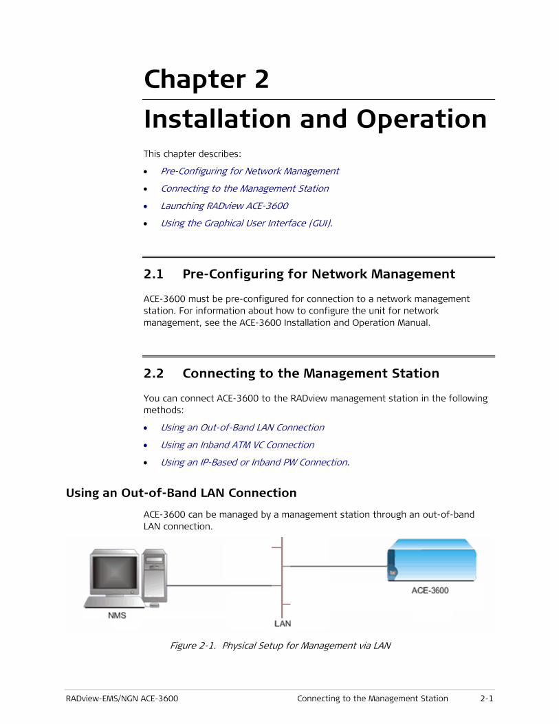
Using an Out-of-Band LAN Connection
ACE-3600 can be managed by a management station through an out-of-band LAN connection.
Figure 2-1. Physical Setup for Management via LAN

Chapter 2 Installation and Operation User's Manual
2-2 Connecting to the Management Station RADview-EMS/NGN ACE-3600
To set up management access via a LAN:
1. Connect ACE-3600 to the LAN via one of the ETH ports on the front panel.
2. Log in to ACE-3600 via an ASCII terminal.
3. Configure ACE-3600 for network management, as described in Configuring for Management, in the ACE-3600 Installation and Operation Manual.
Using an Inband ATM VC Connection
When managed through an inband ATM VC, ACE-3600 is connected to the management station through the ATM network, via one of the active ATM ports.
Figure 2-2. Management via ATM
To set up management access through the ATM port:
1. Connect ACE-3600 to the ATM network via one of the ATM-155 ports on the front panel.
2. Log in to ACE-3600 via an ASCII terminal.
3. Configure ACE-3600 for network management, as described in Configuring for Management, in the ACE-3600 Installation and Operation Manual.
Using an IP-Based or Inband PW Connection
ACE-3600 can be managed by a management station through an out-of-band LAN connection.
Figure 2-3. Management via IP/ETH
To set up management access via a packet-switched network connection:
1. Connect ACE-3600 to the packet-switched network via one of the GbE ports on the front panel.
2. Log in to ACE-3600 via an ASCII terminal.
User's Manual Chapter 2 Installation and Operation
RADview-EMS/NGN ACE-3600 Launching RADview ACE-3600 2-3
3. Configure ACE-3600 for network management as described in Configuring for Management, in the ACE-3600 Installation and Operation Manual.
2.3 Launching RADview ACE-3600
The ACE-3600 zoom application can be invoked from the SNMPc Management Console (PC version), HPOV (Unix version), or Network Elements Tree.
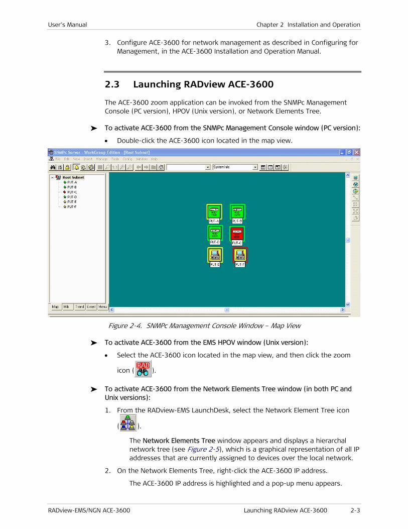
To activate ACE-3600 from the SNMPc Management Console window (PC version):
• Double-click the ACE-3600 icon located in the map view.
Figure 2-4. SNMPc Management Console Window – Map View
To activate ACE-3600 from the EMS HPOV window (Unix version):
• Select the ACE-3600 icon located in the map view, and then click the zoom
icon ( ).
To activate ACE-3600 from the Network Elements Tree window (in both PC and Unix versions):
1. From the RADview-EMS LaunchDesk, select the Network Element Tree icon
( ).
The Network Elements Tree window appears and displays a hierarchal network tree (see Figure 2-5), which is a graphical representation of all IP addresses that are currently assigned to devices over the local network.
2. On the Network Elements Tree, right-click the ACE-3600 IP address.
The ACE-3600 IP address is highlighted and a pop-up menu appears.
Chapter 2 Installation and Operation User's Manual
2-4 Launching RADview ACE-3600 RADview-EMS/NGN ACE-3600
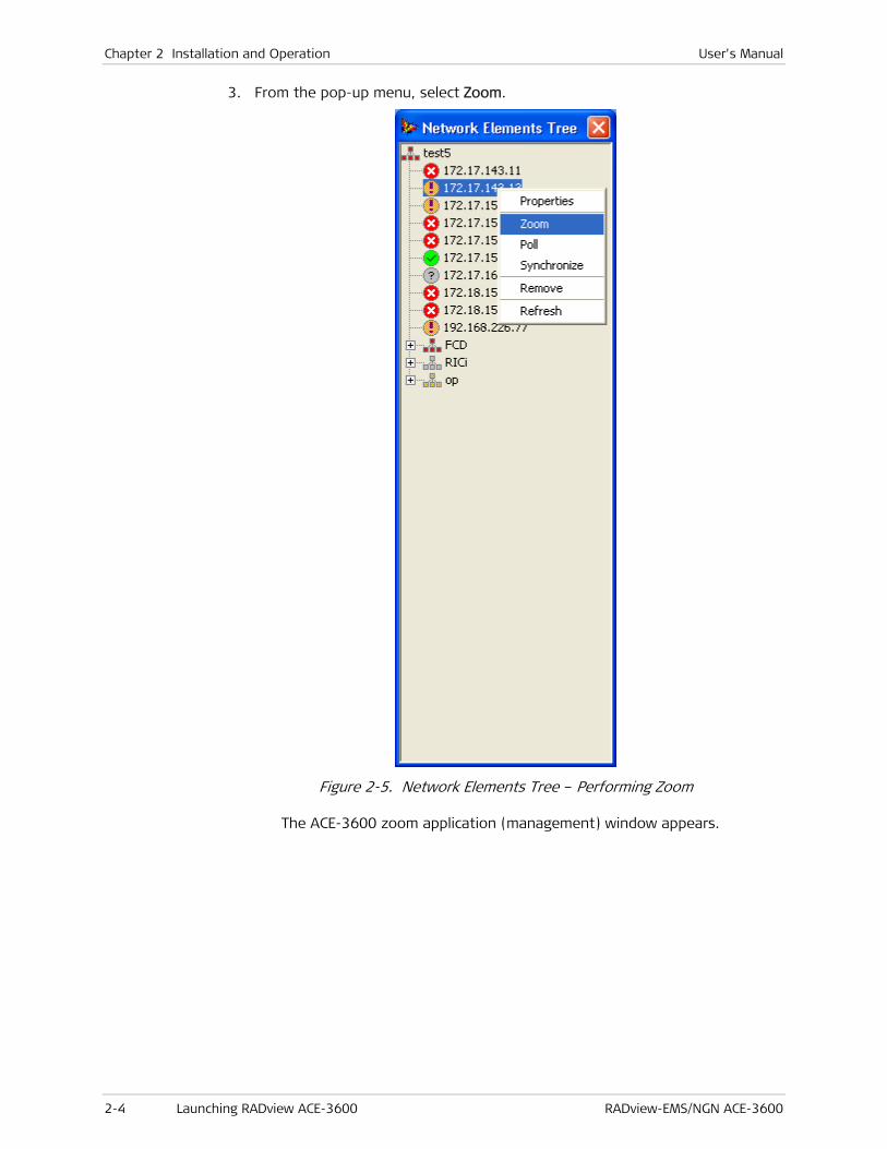
3. From the pop-up menu, select Zoom.
Figure 2-5. Network Elements Tree – Performing Zoom
The ACE-3600 zoom application (management) window appears.
User's Manual Chapter 2 Installation and Operation
RADview-EMS/NGN ACE-3600 Using the Graphical User Interface (GUI) 2-5
2.4 Using the Graphical User Interface (GUI)
You can easily configure and monitor the ACE-3600 device, using the zoom application.
The zoom application’s GUI presents an interactive image of the ACE-3600 front panel, and allows you to configure and monitor ACE-3600 at the system (device) level, or at the individual port level.
The GUI is context-sensitive. Selecting the entire device allows you to perform system-level operations, while drilling down to a specific interface or port allows you to perform port-level operations that relate only to that interface.
Using the Device Level Interface
To access the system-level commands:
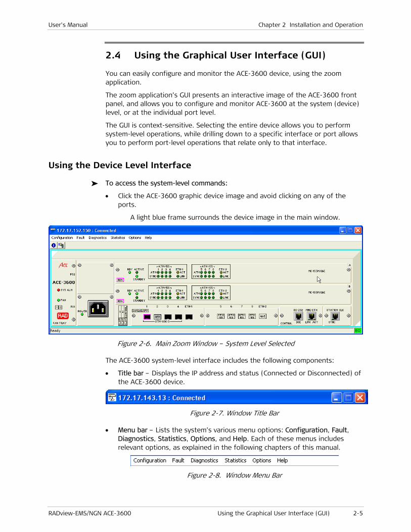
• Click the ACE-3600 graphic device image and avoid clicking on any of the ports.
A light blue frame surrounds the device image in the main window.
Figure 2-6. Main Zoom Window – System Level Selected
The ACE-3600 system-level interface includes the following components:
• Title bar – Displays the IP address and status (Connected or Disconnected) of the ACE-3600 device.
Figure 2-7. Window Title Bar
• Menu bar – Lists the system’s various menu options: Configuration, Fault, Diagnostics, Statistics, Options, and Help. Each of these menus includes relevant options, as explained in the following chapters of this manual.
Figure 2-8. Window Menu Bar

Chapter 2 Installation and Operation User's Manual
2-6 Using the Graphical User Interface (GUI) RADview-EMS/NGN ACE-3600
• Toolbar – Two buttons are available on the toolbar:
System Info –Displays the System Information window, which summarizes the status and general details of the ACE-3600 device.
Poll Agent – When clicked, the NMS polls the SNMP agent.
• Status bar – Displays the system status information via text.
Figure 2-9. Window Status Bar
Using the Port Level Interface
Prior to accessing the port-level commands, the color of each port in the graphic device image indicates the operational status of that port. The displayed status is based on both the polling and interface notifications. The color indicators are:
• No Color – The port is OK and no test is currently running.
• Light Blue – The port is currently testing.
• Magenta – The port has active alarms.
To access the port-level commands:
1. Click the required port in the ACE-3600 graphic device image.
A light blue frame surrounds the selected port in the device image.
2. Click the Zoom In button ( ), located on the toolbar. Alternatively, from the Configuration menu, select Zoom In.
The port window appears and displays a graphic representation of the port.
Figure 2-10. ATM-155 Port-Level Window
User's Manual Chapter 2 Installation and Operation
RADview-EMS/NGN ACE-3600 Using the Graphical User Interface (GUI) 2-7
The port level window includes the following components:
• Menu Bar – Lists the various menu options for the currently selected layer. The available options change when you select a different layer.
• Port layers – Labeled rectangles that represent the different port layers available for configuration in the selected port. Each layer is managed individually.
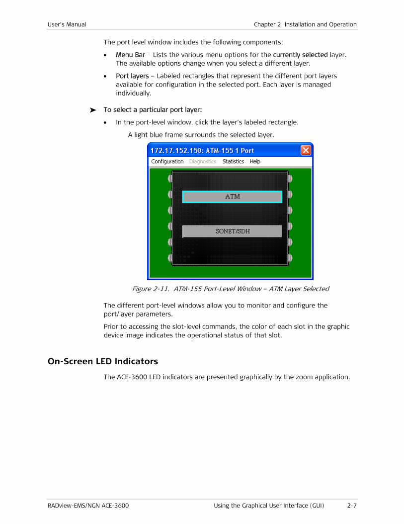
To select a particular port layer:
• In the port-level window, click the layer’s labeled rectangle.
A light blue frame surrounds the selected layer.
Figure 2-11. ATM-155 Port-Level Window – ATM Layer Selected
The different port-level windows allow you to monitor and configure the port/layer parameters.
Prior to accessing the slot-level commands, the color of each slot in the graphic device image indicates the operational status of that slot.
On-Screen LED Indicators
The ACE-3600 LED indicators are presented graphically by the zoom application.

Chapter 2 Installation and Operation User's Manual
2-8 Using the Graphical User Interface (GUI) RADview-EMS/NGN ACE-3600
Figure 2-12. ACE-3600 Graphical Front Panel
The following list summarizes the function of all LED indicators in ACE-3600:
Hot-Swappable Power Supplies
POWER (green/red)
Green: Power supply is OK.
Red: Power supply failure.
Fan Tray SYS ALM (green/red)
Green: No system alarm is detected.
Red: At least one system alarm has been detected.
FAN (green/red)
Green: All fans are working properly.
Red: At least one fan is not working properly.
Main Module RDY (green)
On: Self-test has been completed successfully.
Blinking: Self-test has failed.
ACTIVE (green)
On: This main module is in Active mode.
Off: This main module is not in Active mode.
STANDBY (green)
On: This main module is in Standby mode.
Off: This main module is not in Standby mode.
ATM-155 SYNC 1–4, 5–8 (green)
On: The port's physical layer is synchronized.
Off: The port's physical layer is not synchronized.
Blinking: RDI has been detected.
ATM-155 ATM 1–4, 5–8 (green)
On: ATM cells are being received or transmitted.
Off: ATM cells are not being received or transmitted.
ETH 1/2 LINK (green)
On: Gigabit Ethernet link is detected.
Off: Gigabit Ethernet link is not detected.
User's Manual Chapter 2 Installation and Operation
RADview-EMS/NGN ACE-3600 Using the Graphical User Interface (GUI) 2-9
ETH 1/2 ACT (green)
On: Frames are being received or transmitted.
Off: Frames are not being received or transmitted.
MNG-ETH Control Port
LINK (green)
On: Ethernet link is detected.
Off: Ethernet link is not detected.
ACT (yellow)
On: ETH frames are being received or transmitted.
Off: ETH frames are not being received or transmitted.
Station Clock Port SYNC (green)
On: E1/T1 physical layer is synchronized.
Off: E1/T1 physical layer is not synchronized.

Chapter 2 Installation and Operation User's Manual
2-10 Using the Graphical User Interface (GUI) RADview-EMS/NGN ACE-3600

RADview-EMS/NGN ACE-3600 Setting the System Parameters 3-1
Chapter 3
Configuration Management This chapter describes in detail the following configuration options available for ACE-3600 using the RADview GUI:
a. Setting the System Parameters – which includes:
Entering System Information
Setting the Date and Time
Setting the Syslog Parameters
Defining Managers
Setting the OV Severity
Configuring Access to Web and Telnet.
b. Setting the Operational Parameters– which includes:
Configuring Ports
Setting the Protection Parameters
Defining the Clock Source
Configuring Traffic Descriptors
Configuring OAM
Configuring the ATM Cross-Connect (XC) Parameters
Configuring the Router
Configuring MPLS Parameters
Configuring Multiservice over PSN Parameters.
c. Additional Tasks– which includes:
Polling the Hardware
Resetting the Hardware
Restoring the Default System Configuration
Viewing and Swapping Software Files
Saving/Deleting the Default Configuration File
Downloading Software via a TFTP Server
Downloading a Preset Configuration via a TFTP Server.

Chapter 3 Configuration Management User's Manual
3-2 Setting the System Parameters RADview-EMS/NGN ACE-3600
3.1 Setting the System Parameters
This section describes how to configure general system parameters needed for normal operation of the unit:
• Entering System Information
• Setting the Date and Time
• Setting the Syslog Parameters
• Defining Managers
• Setting the OV Severity
• Configuring Access to Web and Telnet.
Entering System Information
The system information option enables you to view and set general information about the ACE-3600 unit.
The ACE-3600 management software allows you to assign a name to the unit, specify its location to distinguish it from the other devices installed in your system, and assign a contact person.
This feature is available even when there is no communication with the agent.
To view the system information:
1. Click the ACE-3600 graphic device image.
A light blue frame surrounds the device image and the main menu becomes available.
2. From the main menu, select Configuration>System Info.
or
On the main toolbar, click the Info button ( ).
The System Information dialog box appears.
User's Manual Chapter 3 Configuration Management
RADview-EMS/NGN ACE-3600 Setting the System Parameters 3-3
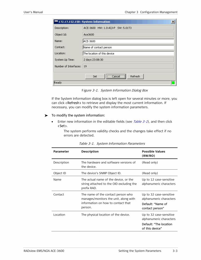
Figure 3-1. System Information Dialog Box
If the System Information dialog box is left open for several minutes or more, you can click <Refresh> to retrieve and display the most current information. If necessary, you can modify the system information parameters.
To modify the system information:
• Enter new information in the editable fields (see Table 3-1), and then click <Set>.
The system performs validity checks and the changes take effect if no errors are detected.
Table 3-1. System Information Parameters
Parameter Description Possible Values (RW/RO)
Description The hardware and software versions of
the device.
(Read only)
Object ID The device’s SNMP Object ID. (Read only)
Name The actual name of the device, or the
string attached to the OID excluding the
prefix RAD.
Up to 12 case-sensitive
alphanumeric characters
Contact The name of the contact person who
manages/monitors the unit, along with
information on how to contact that
person.
Up to 32 case-sensitive
alphanumeric characters
Default: “Name of
contact person”
Location The physical location of the device. Up to 32 case-sensitive
alphanumeric characters
Default: “The location
of this device”

Chapter 3 Configuration Management User's Manual
3-4 Setting the System Parameters RADview-EMS/NGN ACE-3600
Parameter Description Possible Values (RW/RO)
System Up Time The period of time that the system has
been running.
Format: d days
hh:mm:ss (Read only)
Number of
Interfaces
The number of physical and logical
device interfaces.
(Read Only)
Even if there is no communication with the agent, ACE-3600 obtains and saves the following parameters concerning system information:
• Description
• Name
• Contact
• Location
Setting the Date and Time
ACE-3600 allows you to set the date and time of its internal clock. Log events are recorded according to the set date and time. In addition, you can set the unit to automatically retrieve the current date and time from an SNTP server..
To set the date and time:
1. Click the ACE-3600 graphic device image.
A light blue frame surrounds the device image and the main menu becomes available.
2. From the main menu, select Configuration.
The Configuration menu appears.
Figure 3-2. Configuration Menu
3. From the Configuration menu, select Date & Time.
The Date & Time dialog box appears.
Note

User's Manual Chapter 3 Configuration Management
RADview-EMS/NGN ACE-3600 Setting the System Parameters 3-5
Figure 3-3. Date and Time Dialog Box
Table 3-2. Date and Time Parameters
Parameter Description Possible Values (RW/RO)
Date
Actual date.
You can type a different date or select a
different date from the drop-down
calendar (see Changing the Date). The
date is subject to validity checks.
Format: YYYY-MM-DD
Time
Actual time.
You can type a different time. The
entered time is subject to validity checks.
Format: hh:mm:ss
Summer Time
Mode.
Displays the summer time (daylight
saving time) configuration that you set
(see Setting the Summer Time Parameters).
Chapter 3 Configuration Management User's Manual
3-6 Setting the System Parameters RADview-EMS/NGN ACE-3600
Parameter Description Possible Values (RW/RO)
Offset (minutes) The fixed number of minutes that should
be added to the local time during the
daylight saving time period.
Available only when Summer mode is
'recurring" or 'date'.
0 -720
Default: 60
SNTP Mode. Availability and type of the SNTP time
retrieval.
Set the system NTP mode to one of the
following:
• Disable – The SNTP service is
disabled.
• Broadcast client - ACE-3600 works in
SNTP mode as a broadcast client.
• Unicast client - ACE-3600 works in
SNTP mode as a Unicast client.
Disable
Broadcast Client
Unicast Client
Default: Disable
Time Zone Select Greenwich Mean Time (GMT)
offset of the manually entered time.
Available only when SNTP mode is
'Unicast Client'.
GMT –12:00,
GMT –11:00
GMT –1:00,
GMT,
GMT +1:00
GMT +12:00
Server IP Address IP address of the SNTP server.
Available only when SNTP mode is
'Unicast Client'.
IP Address
Update Interval
(min)
The required delay in minutes between
automatic SNTP request initiations.
Available only when SNTP mode is
'Unicast Client'.
1…1440 min
Default: 60
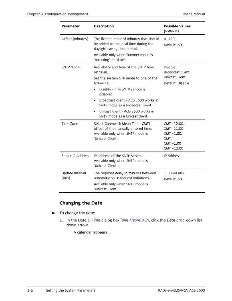
Changing the Date
To change the date:
1. In the Date & Time dialog box (see Figure 3-3), click the Date drop-down list down arrow.
A calendar appears.

User's Manual Chapter 3 Configuration Management
RADview-EMS/NGN ACE-3600 Setting the System Parameters 3-7
Figure 3-4. Drop-Down Calendar
2. In the drop-down calendar, select the year, month, and day.
The selected date is displayed in Date.
Validating the Date and Time
To validate the date and time:
• In the Date & Time dialog box (see Figure 3-3), click <Apply>.
ACE-3600 validates the date and time and SNTP entries:
The day may be 31 only if the month is 1, 3, 5, 7, 8, 10, or 12.
The day cannot be 30 if the month is 2.
The day cannot be 29 if the month is 2, unless the year can be divided by four.
The day cannot be 29 if the month is 2, and the year can be divided by 100 but not by 400.
If the date is found to be invalid, an invalid date error message is displayed in red on the status bar, and the date is not set.
If the combination of day, month, and year is nonexistent, ACE-3600 issues the subsequent valid date in the next month (for example, if you enter 31/9/02, it is automatically converted to 01/10/02).
If the entered time is not valid, an invalid time error message appears in red on the status bar, and the time is not set.
Setting the Summer Time Parameters
The summer time parameters define whether/how the unit should automatically change its internal time when daylight saving time is applied in the geographical region where ACE-3600 is installed. This feature can be disabled, activated on a specific date, or activated to customarily recur every year.
The Summer Time changes are preset to change automatically.

Chapter 3 Configuration Management User's Manual
3-8 Setting the System Parameters RADview-EMS/NGN ACE-3600
You can configure the summer time parameters in one of the following modes:
• Date (see Setting Date Mode Parameters)
• Recurring (see Setting Recurring Mode Parameters)
• Disable (see Disabling the Summer Time Feature).
Setting Date Mode Parameters
Configuring the summer time parameters in "date" mode sets the daylight saving time shifting to occur once on a specific date.
To set the summer time date mode:
1. In the Date & Time dialog box (see Figure 3-3), in the Summer Time section, in Mode, select "Date".
The Summer Time date configuration dialog box is displayed.
Figure 3-5. Summer Time Date Configuration Dialog Box
Table 3-3. Summer Time – Date Mode Parameters
Parameter Description Possible Values (RW/RO)
Mode The summer time mode. (Read only)
Start Date The specific date (year-specific) on
which the daylight saving time begins.
Format: YYYY-MM-DD
Start Time The specific time (hour and minute) at
which the daylight saving time begins, on
the start date.
Format: HH:MM
End Date The specific date (year-specific) on
which the daylight saving time ends. The
end date cannot precede or be the same
as the start date.
Format: YYYY-MM-DD
End Time The specific time (hour and minute) at
which the daylight saving time ends, on
the end date.
Format: HH:MM

User's Manual Chapter 3 Configuration Management
RADview-EMS/NGN ACE-3600 Setting the System Parameters 3-9
2. Enter values for the date parameters, as required, and then click <OK>.
The Date & Time dialog box is updated with the selected values.
Setting Recurring Mode Parameters
Configuring the summer time parameters in "recurring" mode sets the daylight saving time shifting to recur periodically.
To set the summer time recurring mode:
1. In the Date & Time dialog box (see Figure 3-3), in the Summer Time section, in Mode, select "Recurring".
The Summer Time recurring configuration dialog box is displayed.
Figure 3-6. Summer Time Recurring Configuration Dialog Box
Table 3-4. Summer Time – Recurring Mode Parameters
Parameter Description Possible Values (RW/RO)
Mode The summer time mode. (Read only)
Start Week in
Month
The chronological week of the month in
which the daylight saving time should
begin every year.
First
Second
Third
Fourth
Last
Start Weekday The specific day of the week on which
the daylight saving time should begin
every year.
Sunday, Monday,
Tuesday, Wednesday,
Thursday, Friday,
Saturday

Chapter 3 Configuration Management User's Manual
3-10 Setting the System Parameters RADview-EMS/NGN ACE-3600
Parameter Description Possible Values (RW/RO)
Start Month The specific month in which the daylight
saving time should begin every year.
January, February,
March, April, May, June,
July, August, September,
October, Novermber,
December
Start Time The specific time (hour and minute) at
which the daylight saving time should
begin every year.
Format HH:MM.
00:00 – 23:59
End Week in
Month
The chronological week of the month in
which the daylight saving time should
end every year.
First
Second
Third
Fourth
Last
End Weekday The specific day of the week on which
the daylight saving time should end
every year.
Sunday, Monday,
Tuesday, Wednesday,
Thursday, Friday,
Saturday
End Month The specific month in which the daylight
saving time should end every year.
January, February,
March, April, May, June,
July, August, September,
October, Novermber,
December
End Time The specific time (hour and minute) at
which the daylight saving time should
end every year.
Format HH:MM.
00:00 – 23:59
End Month The specific month in which the daylight
saving time should end every year.
January, February,
March, April, May, June,
July, August, September,
October, Novermber,
December
2. Enter values for the recurring parameters, as required, and then click <OK>.
The Date & Time dialog box (see Figure 3-3) is updated with the selected values.
Disabling the Summer Time Feature
To disable the summer time feature:
• In the Date & Time dialog box (see Figure 3-3), in the Summer Time section, in Mode, select "Disable", and then click <OK>.
The Summer Time section does not appear in the Date & Time dialog box.
User's Manual Chapter 3 Configuration Management
RADview-EMS/NGN ACE-3600 Setting the System Parameters 3-11
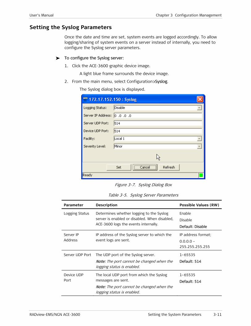
Setting the Syslog Parameters
Once the date and time are set, system events are logged accordingly. To allow logging/sharing of system events on a server instead of internally, you need to configure the Syslog server parameters.
To configure the Syslog server:
1. Click the ACE-3600 graphic device image.
A light blue frame surrounds the device image.
2. From the main menu, select Configuration>Syslog.
The Syslog dialog box is displayed.
Figure 3-7. Syslog Dialog Box
Table 3-5. Syslog Server Parameters
Parameter Description Possible Values (RW)
Logging Status Determines whether logging to the Syslog
server is enabled or disabled. When disabled,
ACE-3600 logs the events internally.
Enable
Disable
Default: Disable
Server IP
Address
IP address of the Syslog server to which the
event logs are sent.
IP address format;
0.0.0.0 –
255.255.255.255
Server UDP Port The UDP port of the Syslog server.
Note: The port cannot be changed when the logging status is enabled.
1–65535
Default: 514
Device UDP
Port
The local UDP port from which the Syslog
messages are sent.
Note: The port cannot be changed when the logging status is enabled.
1–65535
Default: 514

Chapter 3 Configuration Management User's Manual
3-12 Setting the System Parameters RADview-EMS/NGN ACE-3600
Parameter Description Possible Values (RW)
Facility Identifies the software module, task, or
function, from which the Syslog messages are
sent.
Local 1 – Local 7
Default: Local 1
Severity Level.. Only events with severity equal to or
exceeding the selected severity level are sent.
The severity levels are:
• Critical – corresponds to the Emergency
(0) severity level of Syslog
• Major – corresponds to the Alert (1) and
Critical (2) severity levels of Syslog
• Minor – corresponds to the Error (3)
severity level of Syslog
• Warning – corresponds to the Warning (4)
severity level of Syslog
• Event – corresponds to the Notice (5)
severity level of Syslog
• Info – corresponds to the Informational
(6) severity level of Syslog
• Debug – corresponds to the Debug (7)
severity level of Syslog
Note: The severity level can be changed only when the logging status is disabled.
Critical
Major
Minor
Warning
Event
Info
Debug
Default: Minor
3. Enter values for the Syslog parameters, as required, and then click <Set>.
The Syslog server parameters are updated.
Defining Managers
If ACE-3600 is to be managed via a network management station (NMS), it is necessary to define the location of network managers (that is, terminals) that can access the unit via inband or out-of-band management channels.
The Manager List displays the IP addresses of the currently defined managers that can establish SNMP connectivity with the device and control its functions.
In the Manager List dialog box, you can do the following:
• Define a new manager (see Adding Managers).
• Change manager information (see Modifying Manager Mask Traps)
• Remove a manager from the manager list (see Removing Managers).
To display the manager list:
1. Click the ACE-3600 graphic device image.
A light blue frame surrounds the device image.
2. From the main menu, select Options.
User's Manual Chapter 3 Configuration Management
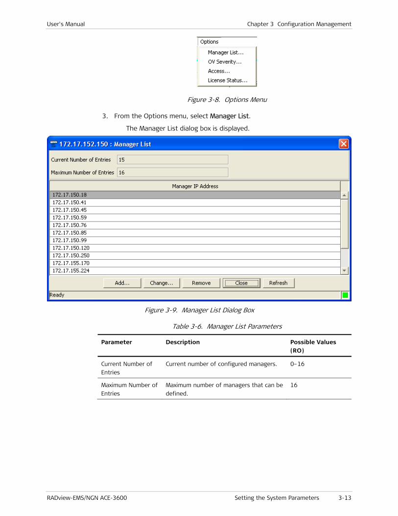
RADview-EMS/NGN ACE-3600 Setting the System Parameters 3-13
Figure 3-8. Options Menu
3. From the Options menu, select Manager List.
The Manager List dialog box is displayed.
Figure 3-9. Manager List Dialog Box
Table 3-6. Manager List Parameters
Parameter Description Possible Values (RO)
Current Number of
Entries
Current number of configured managers. 0–16
Maximum Number of
Entries
Maximum number of managers that can be
defined.
16

Chapter 3 Configuration Management User's Manual
3-14 Setting the System Parameters RADview-EMS/NGN ACE-3600
Parameter Description Possible Values (RO)
Manager IP Address The manager's IP address.
Note:
• The manager's IP address cannot be the same as the subnet of an existing host, unless it is attached to it.
• Multicast, broadcast, all ones, and all zero IPs, are not allowed.
• Address parts that are not subnet cannot be all zeros or all ones.
• The manager's IP address cannot be changed dynamically (on-the-fly)
0.0.0.0 –
255.255.255.255
Adding Managers
The Managers List can have up to 16 managers. If this maximum has not been reached, you can add managers to the list.
The <Add> button is disabled when the table has the maximum number of managers.
To add a manager:
1. In the Manager List dialog box (see Figure 3-9), click <Add>.
The Add Manager dialog box is displayed.
Figure 3-10. Add Manager Dialog Box
Table 3-7. Add Manager Parameter
Parameter Description Possible Values
Manager IP
Address
The IP address of the workstation to be
defined as manager.
0.0.0.0 –
255.255.255.255
2. In Manager IP Address, type the IP address of the workstation to be defined as manager.
3. Click <Mask Traps> to define the mask traps for this manager (see Masking Traps).
The Mask Traps dialog box appears (see Figure 3-12).
Note

User's Manual Chapter 3 Configuration Management
RADview-EMS/NGN ACE-3600 Setting the System Parameters 3-15
4. In the Mask Traps dialog box, select the checkboxes of the parameters to activate the required masks (see Table 3-8), and then click <OK>.
The Add Manager dialog box reappears.
5. Click <Set>.
The system validates the new manager (see System Validation of a New Manager). Once validated, the manager is added to the Manager List (see Figure 3-9).
System Validation of a New Manager
ACE-3600 checks whether:
• The Manager IP Address is valid.
If it is found to be invalid, an error message appears.
• The added manager already exists in the table.
If so, an error message appears.
• The manager's IP address is different than all host IP addresses.
If it is not, an error message appears.
Modifying Manager Mask Traps
You can reconfigure the mask traps of an existing manager.
The <Change> button is disabled until you select an entry.
To reconfigure a manager’s mask traps:
1. In the Manager List dialog box (see Figure 3-9), select the row of a manager that you want to reconfigure, and then click <Change>.
The Change Manager dialog box appears.
Figure 3-11. Change Manager Dialog Box
The Change Manager dialog box has the same parameter – Manager IP Address, that is displayed in the Add Manager dialog box (see Figure 3-10). However, here this parameter is non-editable.
2. Click <Mask Traps> to change the mask traps of the selected manager (see Masking Traps).
The Mask Traps dialog box appears (see Figure 3-12).
Note
Note
Chapter 3 Configuration Management User's Manual
3-16 Setting the System Parameters RADview-EMS/NGN ACE-3600
3. In the Mask Traps dialog box, select the checkboxes of the parameters to activate the required masks (see Table 3-8), and then click <OK>.
The Change Manager dialog box reappears.
4. In the Change Manager dialog box, click <Set>.
The Manager List dialog box (see Figure 3-9) reappears, and the selected manager's mask traps are reconfigured.
Removing Managers
You can delete a manager from the Managers List.
The <Remove> button is disabled until you select an entry.
To remove a manager from the list:
1. In the Manager List dialog box (see Figure 3-9), select the manager you want to remove.
2. Click <Remove>.
The confirmation message “Removing this manager may disconnect NMS” appears.
3. Click <OK>.
The manager is removed from the list.
Masking Traps
Mask traps can be configured for each manager through the Mask Traps dialog box, which is invoked from the Add Manager and Change Manager dialog boxes.
Selecting a parameter in the Mask Traps dialog box (see Figure 3-12), activates the mask. The trap is therefore not sent.
Note

User's Manual Chapter 3 Configuration Management
RADview-EMS/NGN ACE-3600 Setting the System Parameters 3-17
Figure 3-12. Mask Traps Dialog Box
Table 3-8. Mask Traps – Parameters
Parameter Description Possible Values (RW)
Masking Mode
Group of three option buttons:
• All – All the traps are masked.
• None – None of the traps are masked.
• Manual – Traps are enabled or disabled,
manually.
All
None
Manual
Default: Manual
Cold Start The coldStart trap indicates that the Agent
is re-initializing itself in such a way that the
Agent’s configuration may be altered.
Active
Masked
Default: Active

Chapter 3 Configuration Management User's Manual
3-18 Setting the System Parameters RADview-EMS/NGN ACE-3600
Parameter Description Possible Values (RW)
Agent Status The agnStatusChangeTrap is sent whenever
there is a change in the state of the device.
This trap is also used for coloring the Agent
node on the HPOV map.
Active
Masked
Default: Active
TFTP Status The tftpStatusChangeTrap is sent whenever
a TFTP session is opened between the
Agent and the NMS. Masking it faisl the
operation of TFTP applications.
Active
Masked
Default: Active
Authentication
Failure
The authenticationFailureTrap is sent when
an SNMP request is made under a
community name that does not match the
community name in the Agent.
Active
Masked
Default: Masked
Power Failure The agnPowerFailureTrap is sent to indicate
a power failure state.
It is relevant only to a device with two PSUs,
for example, the device cannot send a trap
before one PSU is shut down; only upon a
status change while the other PSU is up.
Active
Masked
Default: Masked
Fan Failure The agnFanFailureTrap is sent to indicate a
fan failure/recovery.
Active
Masked
Default: Masked
Station Clock
Failure
The agnStationClkFailureTrap is sent to
indicate a station clock failure.
Active
Masked
Default: Masked
Module Change The atmAceModuleChangeTrap is sent to
indicate that a card (module) in the unit has
been replaced/changed.
Active
Masked
Default: Masked
Module Mismatch The atmAceModuleMismatchTrap is sent to
indicate that the inserted card (module)
does not match the configured card
(module).
Active
Masked
Default: Masked
Redundancy Status The sysRedundancyStatusTrap indicates the
redundancy status.
Active
Masked
Default: Masked
Redundancy Active
Card
The sysRedundancyActiveCardTrap indicates
which card (module) is currently active.
Active
Masked
Default: Masked
Redundancy Active
Port
The sysRedundancyActivePortTrap indicates
which port is currently active.
Active
Masked
Default: Masked

User's Manual Chapter 3 Configuration Management
RADview-EMS/NGN ACE-3600 Setting the System Parameters 3-19
Parameter Description Possible Values (RW)
APS Active Port The apsActiveChannelTrap indicates the APS
active port.
Active
Masked
Default: Masked
License Update The licenseUpdateTrap indicates that the
license has been updated.
Active
Masked
Default: Masked
Upload Data The agnUploadDataTrap is generated for
completed upload operations.
Active
Masked
Default: Active
Self Test Result The agnSelfTestResultChangeTrap informs
of any change in the unit's self test results.
Active
Masked
Default: Masked
Port Status The prtStatusChangeTrap is sent whenever
the SFP port is removed from or inserted
into the device.
Active
Masked
Default: Masked
Link Up/Down • LinkDown – Indicates that the operation
status of the ETH link is down.
• LinkUp – Indicates that the operation
status of the ETH link is up.
Active
Masked
Default: Masked
LOS The atmAceAlarmLOS trap is sent when
there is a condition indicating that the
receiving equipment has lost the received
signal.
Active
Masked
Default: Masked
LOF The atmAceAlarmLOF trap is sent when
there is a condition indicating that the
receiving equipment has lost frame
delineation.
Active
Masked
Default: Masked
LCD The atmAceAlarmLCD trap is sent to indicate
a Loss of Cell Delineation condition.
Active
Masked
Default: Masked
SLM The atmAceAlarmSLM trap is sent to
indicate a Signal Line Mismatch condition.
Active
Masked
Default: Masked
LOP The atmAceAlarmSLM trap is sent to
indicate a condition that the receiver
equipment has lost the pointer to the start
of cell in the payload.
Active
Masked
Default: Masked

Chapter 3 Configuration Management User's Manual
3-20 Setting the System Parameters RADview-EMS/NGN ACE-3600
Parameter Description Possible Values (RW)
Line AIS The atmAceAlarmLineAIS trap is sent by a
device when it detects an error condition or
receives an error condition from another
unit in the transmission line.
Active
Masked
Default: Masked
Path AIS The atmAceAlarmPathAIS trap is sent by a
device when it detects an error condition or
receives an error condition from another
unit in the transmission path.
Active
Masked
Default: Masked
Line RDI The atmAceAlarmLineRDI trap is sent to
indicate a Remote Line Defect Indication
condition.
Active
Masked
Default: Masked
Path RDI The atmAceAlarmPathRDI trap is sent to
indicate a Remote Path Defect Indication
condition.
Active
Masked
Default: Masked
Section BIP The atmAceAlarmSectionBIP trap is sent to
indicate an error performance of the link at
the Section layer.
Bit Interleaved Parity is a method used at
the Physical layer to monitor the error
performance of the link. A check bit is sent
in the link overhead covering the previous
block or frame.
Active
Masked
Default: Masked
Line BIP The atmAceAlarmLineBIP trap is sent to
indicate an error performance of the link at
the Line layer.
Active
Masked
Default: Masked
Path BIP The atmAceAlarmPathBIP trap is sent to
indicate an error performance of the link at
the Path layer.
Active
Masked
Default: Masked
Line FEBE The atmAceAlarmLineFEBE trap is sent to
indicate that a bit error(s) has been
detected at the Physical layer at the far-end
of the link.
This is used to monitor bit error
performance of the link in the Line layer.
Active
Masked
Default: Masked
Path FEBE The atmAceAlarmPathFEBE trap is sent to
indicate that a bit error(s) has been
detected at the Physical layer at the far-end
of the link.
This is used to monitor bit error
performance of the link in the Path layer.
Active
Masked
Default: Masked

User's Manual Chapter 3 Configuration Management
RADview-EMS/NGN ACE-3600 Setting the System Parameters 3-21
Parameter Description Possible Values (RW)
PW Up/Down The PWDOWN/PWUp trap indicates whether a
pseudowire is up or down.
Active
Masked
Default: Masked
BFD Session
Up/Down
The bfdSessUp/bfdSessDown alarm tap
indicates whether the BFD connectivity
check session is up or down.
Active
Masked
Default: Masked
LDP Session
Up/Down
The plsLdpSessionUp/mplsLdpSessionDown
alarm trap indicates whether the label
distribution protocol session is up or down.
Active
Masked
Default: Masked
VP AIS Reception The AtmAceAlarmVpAISReception trap is
sent to indicate AIS Reception on a VP
Connection.
Active
Masked
Default: Masked
VC AIS Reception The AtmAceAlarmVcAISReception trap is
sent to indicate AIS Reception on a VC
Connection.
Active
Masked
Default: Masked
VP RDI Reception The AtmAceAlarmVpRDIReception trap is
sent to indicate RDI Reception on a VP
Connection.
Active
Masked
Default: Masked
VC RDI Reception The AtmAceAlarmVcRDIReception trap is
sent to indicate RDI Reception on a VC
Connection.
Active
Masked
Default: Masked
VP Continuity Loss The AtmAceAlarmVpContinuityLoss trap is
sent to indicate a Loss of continuity on a VP
Connection.
Active
Masked
Default: Masked
VC Continuity Loss The AtmAceAlarmVcContinuityLoss trap is
sent to indicate a Loss of continuity on a VC
Connection.
Active
Masked
Default: Masked
VP Loopback
Failure
The AtmAceAlarmVpLoopback trap is sent to
indicate an error resulting from an OAM
Loopback failure in the VP layer.
Active
Masked
Default: Masked
VC Loopback
Failure
The AtmAceAlarmVcLoopback trap is sent to
indicate an error resulting from an OAM
Loopback failure in the VC layer.
Active
Masked
Default: Masked

Chapter 3 Configuration Management User's Manual
3-22 Setting the System Parameters RADview-EMS/NGN ACE-3600
Setting the OV Severity
The OV Severity determines whether the openViewSeverity MIB is attached to the relevant traps. This parameter controls the severity and color of a given trap displayed in the HPOV All Alarms Browser.
To select OV Severity mode:
1. Click the ACE-3600 graphic device image.
A light blue frame surrounds the device image.
2. From the main menu, select Options.
Figure 3-13. Options Menu
3. Select OV Severity.
The OV Severity dialog box appears, displaying the current OV severity state.
Figure 3-14. OV Severity Dialog Box
Table 3-9. OV Severity Parameter
Parameter Description Possible Values (RW)
Attach OV Severity
to Traps
Yes – OV Severity is attached.
No – OV Severity is not attached.
Yes, No
4. From the drop-down list, select Yes to enable OV severity, or No to disable OV severity.
5. Click <Set>.
The selected mode takes effect.
Configuring Access to Web and Telnet
ACE-3600 allows you to check the current status of the Telnet and Web access services, and to change the access permission, as required.

User's Manual Chapter 3 Configuration Management
RADview-EMS/NGN ACE-3600 Setting the System Parameters 3-23
To display the current access services status:
1. Click the ACE-3600 graphic device image.
A light blue frame surrounds the device image.
2. From the main menu, select Options.
Figure 3-15. Options Menu
3. Select Access.
The Access dialog box appears.
Figure 3-16. Access Dialog Box
Table 3-10. Access Parameters
Parameter Description Possible Values (RW)
Telnet Access The current Telnet access status, for
Telnet control.
Enable
Disable
Secured Mode Only
Default: Disable
Web Access The current Web access status, for
Web applications.
Enable
Disable
Secured Mode Only
Default: Disable
To change the access service status:
1. In the Access dialog box (see Figure 3-16) select values for the parameters from the drop-down lists, as required (see Table 3-10).
2. Click <Set>.
The selected mode takes effect.

Chapter 3 Configuration Management User's Manual
3-24 Setting the Operational Parameters RADview-EMS/NGN ACE-3600
3.2 Setting the Operational Parameters
This section describes in detail in the following sections, how to configure the parameters needed for normal operation of the unit:
• Configuring Ports
• Setting the Protection Parameters
• Defining the Clock Source
• Configuring Traffic Descriptors
• Configuring OAM
• Configuring the ATM Cross-Connect (XC) Parameters
• Configuring the Router
• Configuring MPLS Parameters
• Configuring Multiservice over PSN Parameters.
Configuring Ports
ACE-3600 has three types of ports: Ethernet, Gigabit Ethernet, and ATM-155.
You can configure these ports, as described in the following sections:
• Configuring the Ethernet Port
• Configuring the Gigabit Ethernet Ports
• Configuring the ATM-155 Ports.
The Ethernet, Gigabit Ethernet, and ATM-155 ports require physical layer configuration, before logical or application level configuration.
Configuring the Ethernet Port
ACE-3600 has one built-in 100BaseT port for out-of-band management (MNG-ETH), which can be configured.
To configure the Ethernet port parameters:
1. Double-click the Ethernet port (MNG-ETH) on the ACE-3600 device image.
The Ethernet dialog box is displayed.
2. Select the ETHERNET layer.
A light blue frame surrounds the ETHERNET layer’s label, and the top menu bar becomes available.
Note
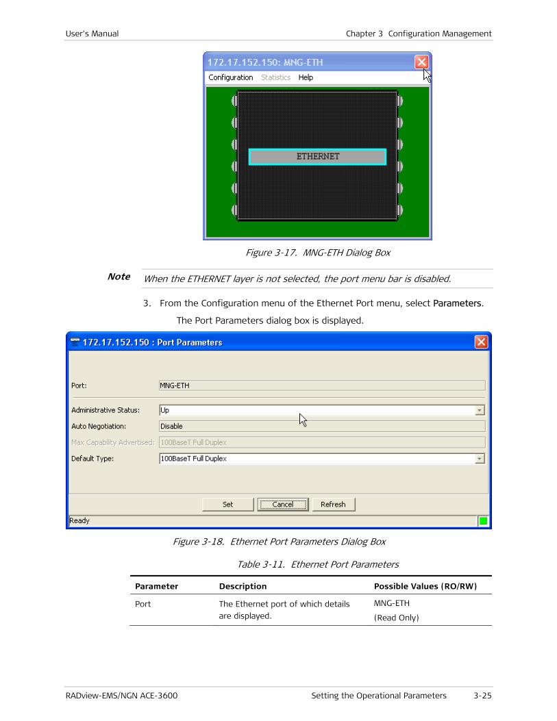
User's Manual Chapter 3 Configuration Management
RADview-EMS/NGN ACE-3600 Setting the Operational Parameters 3-25
Figure 3-17. MNG-ETH Dialog Box
When the ETHERNET layer is not selected, the port menu bar is disabled.
3. From the Configuration menu of the Ethernet Port menu, select Parameters.
The Port Parameters dialog box is displayed.
Figure 3-18. Ethernet Port Parameters Dialog Box
Table 3-11. Ethernet Port Parameters
Parameter Description Possible Values (RO/RW)
Port The Ethernet port of which details
are displayed.
MNG-ETH
(Read Only)
Note

Chapter 3 Configuration Management User's Manual
3-26 Setting the Operational Parameters RADview-EMS/NGN ACE-3600
Parameter Description Possible Values (RO/RW)
Administrative
Status
Up
Down
Default: Up
Auto Negotiation Status of the Auto Negotiation mode
for the selected port.
The Auto Negotiation Mode is
disabled for the out-of-band Ethernet
management port (MNG-ETH), since
it cannot respond in this mode.
Disable
(Read Only)
Max Capability
Advertised
The maximum advertised capability. 1000BaseT Full-Duplex
Default Type The port’s default type. 10BaseT Half-Duplex
10BaseT Full-Duplex
100BaseT Half-Duplex
100BaseT Full-Duplex
Default:
100BaseT Full Duplex.
4. Configure the parameters, as required, for the Ethernet port, and then click <Set>.
The Ethernet port configuration takes effect.
Configuring the Gigabit Ethernet Ports
ACE-3600 includes two electrical or fiber optic Gigabit Ethernet ports (GbE 1 and GbE 2) for user data and inband management. These ports can be configured.
To configure the GbE port parameters:
1. Double-click the Gigabit Ethernet port (Gbe 1 or Gbe 2) on the ACE-3600 device image.
The Gigabit Ethernet Port dialog box is displayed.
2. Select the G-ETHERNET layer.
A light blue frame surrounds the G-ETHERNET layer’s label, and the top menu bar becomes available.

User's Manual Chapter 3 Configuration Management
RADview-EMS/NGN ACE-3600 Setting the Operational Parameters 3-27
Figure 3-19. GbE Port Dialog Box
3. From the Configuration menu of the Gigabit Ethernet Port menu bar, select Parameters.
The Gbe Port Parameters dialog box is displayed.
Figure 3-20. GbE Port Parameters Dialog Box
Table 3-12. GbE Port Parameters
Parameter Description Possible Values (RO/RW)
Port The GbE port of which details are
displayed.
GbE-1, GbE-2
(Read Only)
Administrative
Status
The administrative status of the GbE
port.
Up
Down
Default: Up

Chapter 3 Configuration Management User's Manual
3-28 Setting the Operational Parameters RADview-EMS/NGN ACE-3600
Parameter Description Possible Values (RO/RW)
Auto Negotiation Status of the Auto Negotiation mode
for the selected port. Enable
Disable
Default:
Enable
Max Capability
Advertised
The maximum advertised capability 1000BaseT Full-Duplex
Default Type The port’s default type 10BaseT Half-Duplex
10BaseT Full-Duplex
100BaseT Half-Duplex
100BaseT Full-Duplex
1000BaseT Full Duplex
Default:
1000BaseT Full Duplex
4. Configure the parameters, as required, for the GbE port (see Table 3-12), and then click <Set>.
The GbE port configuration takes effect.
Configuring the ATM-155 Ports
ACE-3600 has up to eight ATM-155 ports that are used for ATM-155 (155 Mbps) fiber optic uplink.
Each ATM-155 port has two layers that can be configured:
• SONET/SDH – the physical layer (see Configuring the SONET/SDH Layer of the ATM-155 Port).
• ATM – the logical layer (see Configuring the ATM Layer of the ATM-155 Port).
Configuring the SONET/SDH Layer of the ATM-155 Port
To configure the SONET/SDH layer of an ATM-155 port:
1. Double-click an ATM-155 port in the ACE-3600 graphic device image.
The ATM-155 Port dialog box appears.

User's Manual Chapter 3 Configuration Management
RADview-EMS/NGN ACE-3600 Setting the Operational Parameters 3-29
Figure 3-21. ATM-155 Port Dialog Box
2. In the ATM-155 Port dialog box, click <SONET/SDH>.
A light blue frame surrounds the SONET/SDH layer.
Figure 3-22. ATM-155 Port – SONET/SDH Layer Selected
3. In the ATM-155 Port menu bar, select Configuration>Parameters.
The ATM-155 port physical layer parameters dialog box appears.
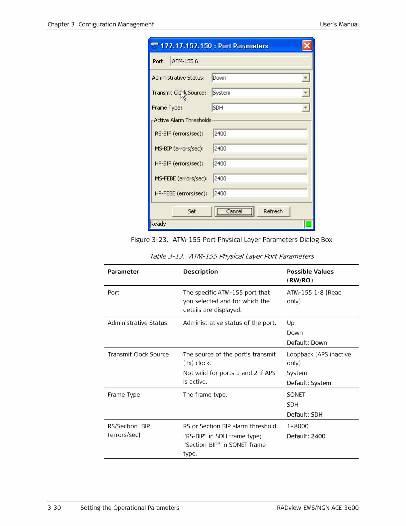
Chapter 3 Configuration Management User's Manual
3-30 Setting the Operational Parameters RADview-EMS/NGN ACE-3600
Figure 3-23. ATM-155 Port Physical Layer Parameters Dialog Box
Table 3-13. ATM-155 Physical Layer Port Parameters
Parameter Description Possible Values (RW/RO)
Port The specific ATM-155 port that
you selected and for which the
details are displayed.
ATM-155 1-8 (Read
only)
Administrative Status Administrative status of the port. Up
Down
Default: Down
Transmit Clock Source The source of the port's transmit
(Tx) clock.
Not valid for ports 1 and 2 if APS
is active.
Loopback (APS inactive
only)
System
Default: System
Frame Type The frame type. SONET
SDH
Default: SDH
RS/Section BIP
(errors/sec)
RS or Section BIP alarm threshold.
“RS-BIP” in SDH frame type;
“Section-BIP” in SONET frame
type.
1–8000
Default: 2400
User's Manual Chapter 3 Configuration Management
RADview-EMS/NGN ACE-3600 Setting the Operational Parameters 3-31
Parameter Description Possible Values (RW/RO)
MS/Line BIP
(errors/sec)
MS or Line BIP alarm threshold.
“MS-BIP” in SDH frame type;
“Line BIP” in SONET frame type
1–8000
Default: 2400
HP/Path BIP (errors/sec) HP or Path BIP alarm threshold.
“HP BIP” in SDH frame type;
“Path BIP” in SONET frame type
1–8000
Default: 2400
MS/Line-FEBE
(errors/sec)
MS or Line FEBE alarm threshold.
“MS FEBE” in SDH frame type;
“Line FEBE” in SONET frame type.
1–8000
Default: 2400
HP/Path FEBE
(errors/sec)
HP or Path FEBE alarm threshold.
“HP FEBE” in SDH frame type;
“Path FEBE” in SONET frame type.
1–8000
Default: 2400
4. Configure the required parameters in the editable fields (see Table 3-13), and then click <Set>.
The system validates the port parameters. Once validated, the changes take effect.
• ACE-3600 checks whether any of the Active Alarm Thresholds are out of range. If so, an error message appears and no change takes effect.
• If Administrative Status is changed to Up and the device is managed through this port, disabling the port disconnects the management.
• When APS is active, the Port Parameters dialog box is for working port 2.
Configuring the ATM Layer of the ATM-155 Port
To configure the ATM layer of an ATM-155 port:
1. Double-click the ATM-155 Port in the ACE-3600 graphic device image.
The ATM-155 Port dialog box appears (see Figure 3-21).
2. In the ATM-155 Port dialog box, click <ATM>.
A light blue frame surrounds the ATM layer.
Note
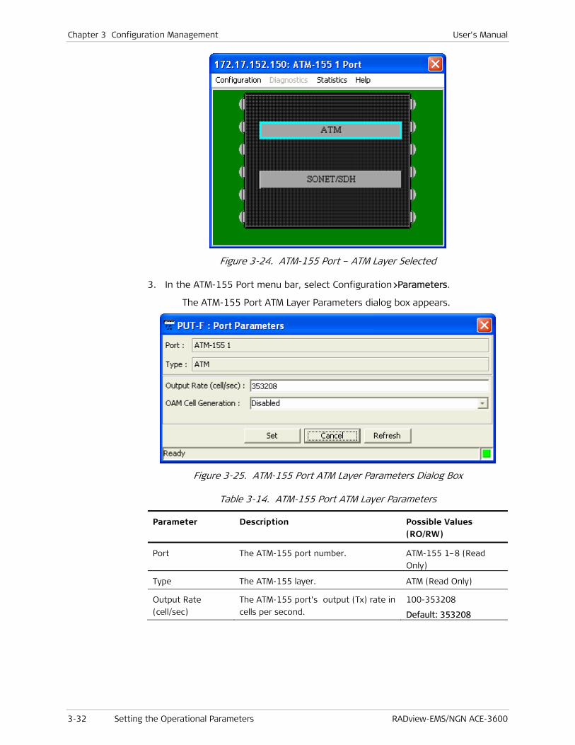
Chapter 3 Configuration Management User's Manual
3-32 Setting the Operational Parameters RADview-EMS/NGN ACE-3600
Figure 3-24. ATM-155 Port – ATM Layer Selected
3. In the ATM-155 Port menu bar, select Configuration>Parameters.
The ATM-155 Port ATM Layer Parameters dialog box appears.
Figure 3-25. ATM-155 Port ATM Layer Parameters Dialog Box
Table 3-14. ATM-155 Port ATM Layer Parameters
Parameter Description Possible Values (RO/RW)
Port The ATM-155 port number. ATM-155 1–8 (Read
Only)
Type The ATM-155 layer. ATM (Read Only)
Output Rate
(cell/sec)
The ATM-155 port’s output (Tx) rate in
cells per second.
100-353208
Default: 353208
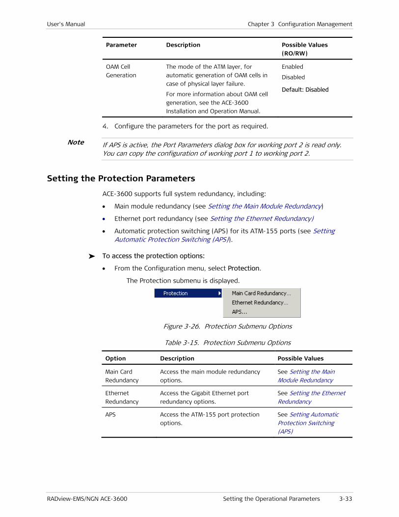
User's Manual Chapter 3 Configuration Management
RADview-EMS/NGN ACE-3600 Setting the Operational Parameters 3-33
Parameter Description Possible Values (RO/RW)
OAM Cell
Generation
The mode of the ATM layer, for
automatic generation of OAM cells in
case of physical layer failure.
For more information about OAM cell
generation, see the ACE-3600
Installation and Operation Manual.
Enabled
Disabled
Default: Disabled
4. Configure the parameters for the port as required.
If APS is active, the Port Parameters dialog box for working port 2 is read only. You can copy the configuration of working port 1 to working port 2.
Setting the Protection Parameters
ACE-3600 supports full system redundancy, including:
• Main module redundancy (see Setting the Main Module Redundancy)
• Ethernet port redundancy (see Setting the Ethernet Redundancy)
• Automatic protection switching (APS) for its ATM-155 ports (see Setting Automatic Protection Switching (APS)).
To access the protection options:
• From the Configuration menu, select Protection.
The Protection submenu is displayed.
Figure 3-26. Protection Submenu Options
Table 3-15. Protection Submenu Options
Option Description Possible Values
Main Card
Redundancy
Access the main module redundancy
options.
See Setting the Main Module Redundancy
Ethernet
Redundancy
Access the Gigabit Ethernet port
redundancy options.
See Setting the Ethernet Redundancy
APS Access the ATM-155 port protection
options.
See Setting Automatic Protection Switching (APS)
Note

Chapter 3 Configuration Management User's Manual
3-34 Setting the Operational Parameters RADview-EMS/NGN ACE-3600
Setting the Main Module Redundancy
ACE-3600 supports the installation of two main modules (main cards) in order to ensure fail-safe operation. If the unit was ordered with two main modules, activate the main module protection feature. Alternatively, if the module protection is disabled, select the main module that the unit should use by default.
Additional features include: setting the WTR time, updating software or configuration, switching between modules, and performing reset. All these functions are available via the Main Card Redundancy dialog box.
To access the Main Card Redundancy menu:
1. From the Protection menu (see Figure 3-26), select Main Card Redundancy.
The Main Card Redundancy dialog box is displayed.
Figure 3-27. Main Card Redundancy Dialog Box
Table 3-16. Main Card Redundancy Options
Parameter Description Possible Values
Active Main Card Indicates which main module (card) is
currently the active one.
Module A (Card A) is located on top of
module B (Card B).
Card A
Card B
Redundancy Status Displays the current redundancy status.
There are four status types:
• OK – Redundancy is up and running
fine.
• Card A/B absent – The specified
module is physically missing.
• Communication loss – The two main
OK
Card A absent
Card B absent
Communication Loss
Hardware Mismatch
Software Mismatch
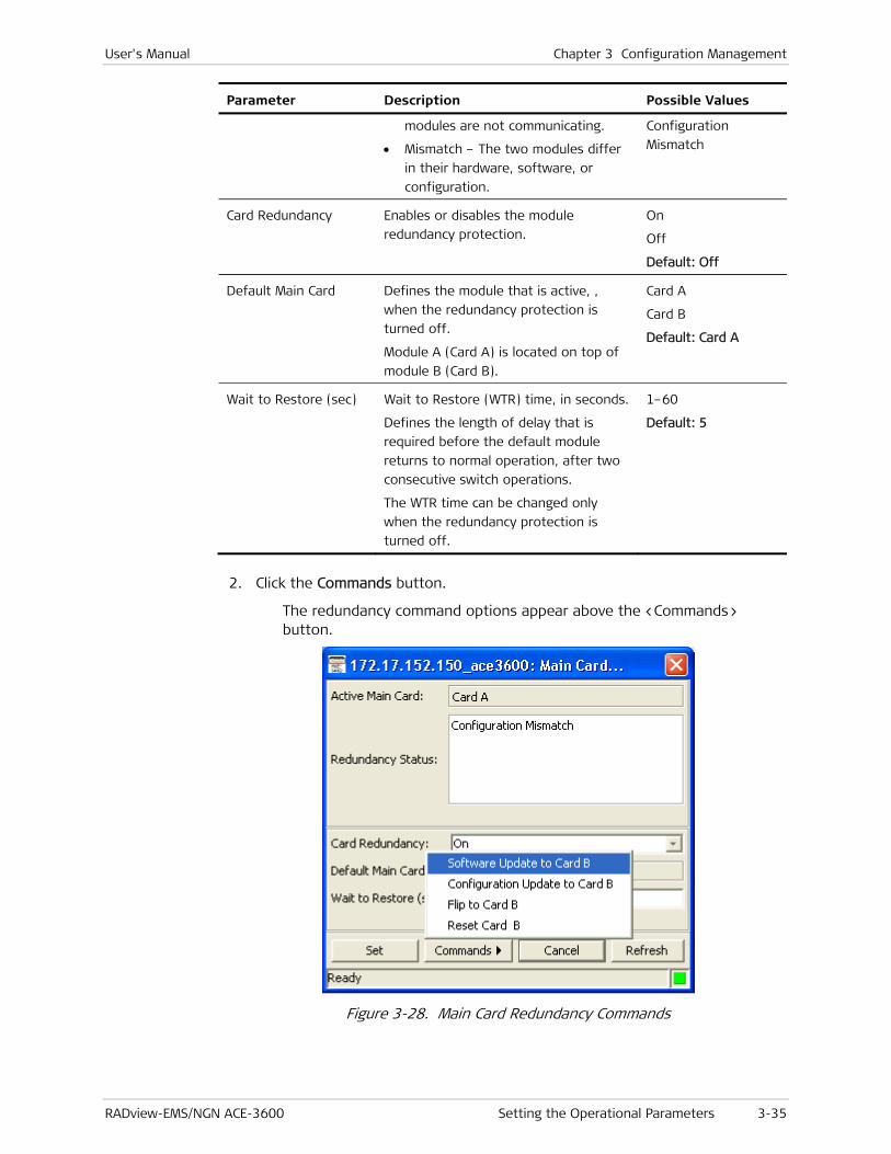
User's Manual Chapter 3 Configuration Management
RADview-EMS/NGN ACE-3600 Setting the Operational Parameters 3-35
Parameter Description Possible Values
modules are not communicating.
• Mismatch – The two modules differ
in their hardware, software, or
configuration.
Configuration
Mismatch
Card Redundancy Enables or disables the module
redundancy protection. On
Off
Default: Off
Default Main Card Defines the module that is active, ,
when the redundancy protection is
turned off.
Module A (Card A) is located on top of
module B (Card B).
Card A
Card B
Default: Card A
Wait to Restore (sec) Wait to Restore (WTR) time, in seconds.
Defines the length of delay that is
required before the default module
returns to normal operation, after two
consecutive switch operations.
The WTR time can be changed only
when the redundancy protection is
turned off.
1–60
Default: 5
2. Click the Commands button.
The redundancy command options appear above the <Commands> button.
Figure 3-28. Main Card Redundancy Commands

Chapter 3 Configuration Management User's Manual
3-36 Setting the Operational Parameters RADview-EMS/NGN ACE-3600
Table 3-17. Main Card Redundancy Commands
Command Description Possible Values
Software Update
to other card
Updates/copies the current software
version (of the active module) onto the
standby module.
Configuration
Update to Card <A or
B> (other card)
Updates/copies the current
configuration (of the active module)
onto the standby module.
Flip to Card <A or B> Switches the control over ACE-3600 to
the other installed main module.
Available only when the redundancy
protection is turned on.
Reset Card <A or B> Resets the standby module (not the
active module).
• Not all redundancy options are applied or activated during the software/configuration update process. A device reset is necessary first.
• The software/configuration update and the switch operations are not available if there is a hardware mismatch (the two modules are not identical), when a module is absent or when the redundancy protection is turned off.
Setting the Ethernet Redundancy
ACE-3600 allows its two Gigabit Ethernet ports (if two are installed) to work in redundancy mode, allowing reliable and uninterrupted service over packet-switched networks. The Gigabit Ethernet ports support the 1:1 and 1+1 automatic protection switching modes according to IEEE 802.3ad.
To access the Ethernet port redundancy options:
• From the Protection menu (see Figure 3-26), select Ethernet Redundancy.
The Ethernet Redundancy Table is displayed.
Note

User's Manual Chapter 3 Configuration Management
RADview-EMS/NGN ACE-3600 Setting the Operational Parameters 3-37
Figure 3-29. Ethernet Redundancy Table Dialog Box
Table 3-18. Ethernet Redundancy Parameters
Parameter Description Possible Values
Group ID ID of the Ethernet redundancy group.
Only one group can be configured.
1
Primary Port The primary (protected) GbE port in the
redundancy group. See Note following
this table.
GbE-1, GbE-2
Default: GbE-1
Secondary Port The secondary (protection) GbE port in
the redundancy group. See Note after
this table.
GbE-1, GbE-2
Default: GbE-2
Mode The method of redundancy. 1+1 (Link aggregation|
1:1
Default:
1:1

Chapter 3 Configuration Management User's Manual
3-38 Setting the Operational Parameters RADview-EMS/NGN ACE-3600
Parameter Description Possible Values
Revertive If 'Revertive' is enabled ('Yes' is
selected), the port protection switching
is reverted back to the primary link as it
was before the link failure, since the
primary link is up again. The revert is
performed once the WTR time is
concluded (see below).
Yes
No
Default: No
Wait to Restore
(sec)
Wait to Restore (WTR) time, in seconds.
WTR is the set delay time required before
the primary port returns to be the active
port, once the port becomes available
after recovering from an error. Relevant
only if 'Revertive' mode is enabled (see
above).
This parameter cannot be changed
dynamically (on-the-fly).
1–720
Default: 300
Adding a new Ethernet Redundancy Group
To add a new Ethernet Redundancy Group
1. In the Ethernet Redundancy Table dialog box (see Figure 3-29, click <Add>.
The Add Ethernet Redundancy Group dialog box is displayed.
Figure 3-30. Add Ethernet Redundancy Group Dialog Box
2. Set the required parameters (see Table 3-18).
3. Click Set.
The new group is added.
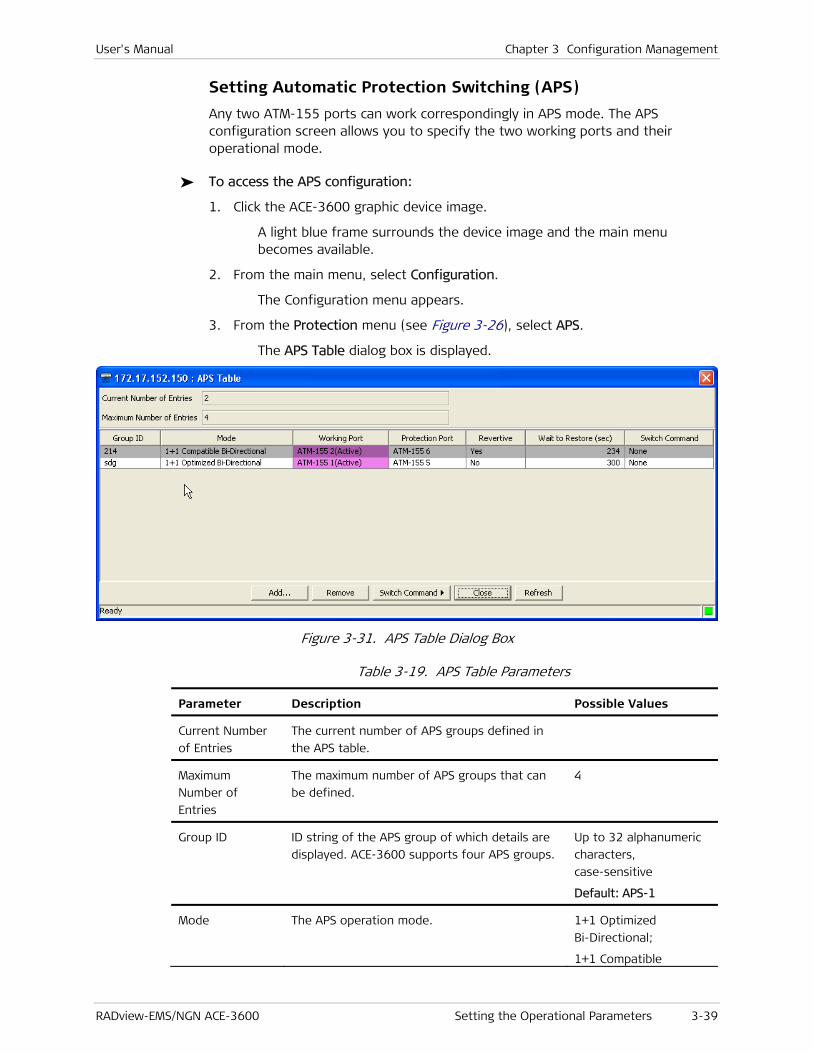
User's Manual Chapter 3 Configuration Management
RADview-EMS/NGN ACE-3600 Setting the Operational Parameters 3-39
Setting Automatic Protection Switching (APS)
Any two ATM-155 ports can work correspondingly in APS mode. The APS configuration screen allows you to specify the two working ports and their operational mode.
To access the APS configuration:
1. Click the ACE-3600 graphic device image.
A light blue frame surrounds the device image and the main menu becomes available.
2. From the main menu, select Configuration.
The Configuration menu appears.
3. From the Protection menu (see Figure 3-26), select APS.
The APS Table dialog box is displayed.
Figure 3-31. APS Table Dialog Box
Table 3-19. APS Table Parameters
Parameter Description Possible Values
Current Number
of Entries
The current number of APS groups defined in
the APS table.
Maximum
Number of
Entries
The maximum number of APS groups that can
be defined.
4
Group ID ID string of the APS group of which details are
displayed. ACE-3600 supports four APS groups.
Up to 32 alphanumeric
characters,
case-sensitive
Default: APS-1
Mode The APS operation mode. 1+1 Optimized
Bi-Directional;
1+1 Compatible

Chapter 3 Configuration Management User's Manual
3-40 Setting the Operational Parameters RADview-EMS/NGN ACE-3600
Parameter Description Possible Values
Bi-Directional
Working Port The APS working port, as well as an indication
that it is active.
ATM-155 1–4 (Active)
Protection Port The APS working port #2. The second port is
automatically selected if APS is enabled on port
#1.
ATM155 5–8
Revertive Indicates whether the Revertive mode is
enabled, i.e. – whether the primary port
returns to normal operation, after a period of
unavailability (if unavailability occurs).
Yes
No
Wait to Restore
(sec)
Wait to Restore time, in seconds.
In APS mode, WTR is the set delay time
required before the primary port returns to
normal operation, once the port becomes
available after recovering from an error.
This parameter cannot be changed dynamically
(on-the-fly).
1–720
Default: 300
Switch
command –
options available
for the 1+1
Optimized Bi-
Directional APS
mode
The APS port switching command. Available
only if the APS mode is enabled (if an APS
group ID exists).
There are four possible switch commands in the
1+1 optimized bi-directional mode:
• None – The initial state, if no command was
applied since the unit's initialization.
• Force Switch – The service is switched from
the primary port to the secondary port. Can
be selected only when No Command or
Clear is the current state.
• Lockout – Freeze the transmitted K-bytes
and the selector's position (the traffic is
taken from the port which is currently
primary) until the lockout is cleared. Lockout
is considered a local request that is not
signaled over the K-bytes. Can be selected
only when No Command or Clear is the
current state.
• Clear – Clear the current command (Force
Switch or Lockout). If the 'Lockout'
command is cleared, the selector and the
transmitted K-bytes return to their previous
state. If the 'Force Switch' command is
cleared, the primary line returns to be the
currently active line, and the local request
for lockout is cleared.
None
Force Switch
Lockout
Clear
Default: None
Switch The APS port switching command. Available None

User's Manual Chapter 3 Configuration Management
RADview-EMS/NGN ACE-3600 Setting the Operational Parameters 3-41
Parameter Description Possible Values
command –
options available
for the 1+1
Compatible Bi-
Directional APS
mode
only if the APS mode is enabled (if an APS
group ID exists).
There are seven possible switch commands in
the 1+1 compatible bi-directional mode:
• None – The initial state, if no command was
applied since the unit's initialization.
• Force Switch to Working – Switches the
normal traffic from the protection port to
the working port, unless an equal or higher
priority request exists. Since a forced switch
has a higher priority than SF or SD on a
working port, this command is carried out
regardless of the current condition of the
working port.
• Force Switch to Protection – Switches the
normal traffic of the working port to the
protection port, unless an equal or higher
priority switch command is in effect, or if an
SF condition exists on the protection port.
• Manual Switch to Working – Switches the
traffic from the protection port back to the
working port, unless an equal or higher
priority request is in effect. Since a manual
switch has lower priority than SF or SD on a
working port, this command is carried out
only if the working port is not in SF or SD
condition.
• Manual Switch to Protection – Switches the
traffic from the working port to the
protection port, unless a failure condition
exists on the protection port or an
equal/higher priority switch command is in
effect. The command is carried out by
issuing a manual switch request for the
normal traffic signal.
• Lockout of Protection – Denies the access
of all normal traffic signals (as well as extra
traffic signals, if applicable) to the
protection port, by issuing a "Lockout of
protection" request, unless an equal
protection switch command is in effect.
• Clear – Clears all externally initiated switch
commands and the WTR time, on the node
to which the command was addressed.
Note:
• Only one command can be applied at a time.
• Issuing a ‘force switch’ or ‘lockout’ is
Clear
Lockout of Protection
Force Switch to
Protection
Manual Switch to
Working
Manual Switch to
Protection
Default: None

Chapter 3 Configuration Management User's Manual
3-42 Setting the Operational Parameters RADview-EMS/NGN ACE-3600
Parameter Description Possible Values
possible only if ‘No Command’ or ‘Clear’ is the current command status.
• ‘No Command’ is only an initial state and cannot be selected as a user command.
• ‘Clear’ is availale only if the current
command value is ‘force switch’ or ‘lockout’
The APS mode cannot be activated if:
• Connections are already configured on the ATM-155 Port 2.
• The transmit (Tx) clock of any port is set on Loopback mode.
• Port activation is disabled.
• The physical layer port configurations of Port 1 and Port 2 are not identical.
You can click <Refresh> to retrieve and display the most current APS information.
Adding APS
In the APS Table dialog box, you can add or remove APS as necessary.
To add an APS :
1. In the APS Table dialog box (see Figure 3-31), click <Add>.
The Add APS Entry dialog box appears.
Figure 3-32. Add APS Entry Dialog Box
The Add button in the APS Table dialog box is disabled when the table is full.
2. Enter the necessary parameters in the editable fields, and then click <Set>.
The system validates the new APS. Once validated, the APS is added to the APS table.
Note
Note
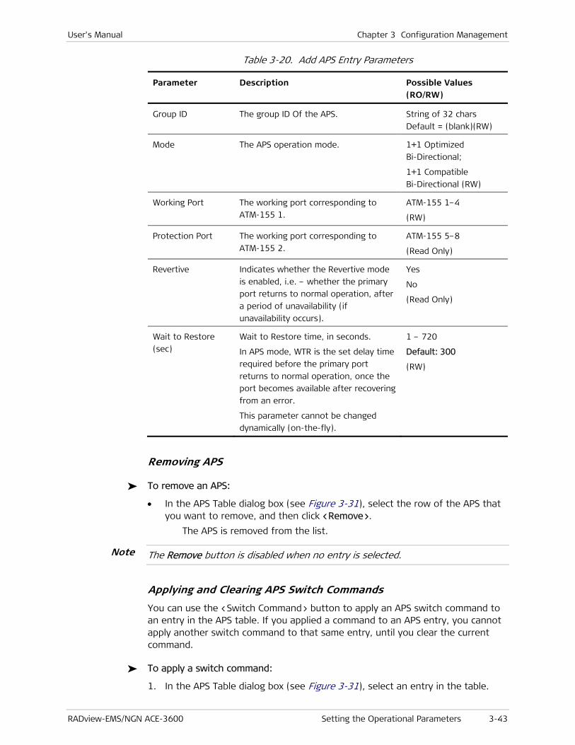
User's Manual Chapter 3 Configuration Management
RADview-EMS/NGN ACE-3600 Setting the Operational Parameters 3-43
Table 3-20. Add APS Entry Parameters
Parameter Description Possible Values (RO/RW)
Group ID The group ID Of the APS. String of 32 chars
Default = (blank)(RW)
Mode The APS operation mode. 1+1 Optimized
Bi-Directional;
1+1 Compatible
Bi-Directional (RW)
Working Port The working port corresponding to
ATM-155 1.
ATM-155 1–4
(RW)
Protection Port The working port corresponding to
ATM-155 2.
ATM-155 5–8
(Read Only)
Revertive Indicates whether the Revertive mode
is enabled, i.e. – whether the primary
port returns to normal operation, after
a period of unavailability (if
unavailability occurs).
Yes
No
(Read Only)
Wait to Restore
(sec)
Wait to Restore time, in seconds.
In APS mode, WTR is the set delay time
required before the primary port
returns to normal operation, once the
port becomes available after recovering
from an error.
This parameter cannot be changed
dynamically (on-the-fly).
1 – 720
Default: 300
(RW)
Removing APS
To remove an APS:
• In the APS Table dialog box (see Figure 3-31), select the row of the APS that you want to remove, and then click <Remove>.
The APS is removed from the list.
The Remove button is disabled when no entry is selected.
Applying and Clearing APS Switch Commands
You can use the <Switch Command> button to apply an APS switch command to an entry in the APS table. If you applied a command to an APS entry, you cannot apply another switch command to that same entry, until you clear the current command.
To apply a switch command:
1. In the APS Table dialog box (see Figure 3-31), select an entry in the table.
Note

Chapter 3 Configuration Management User's Manual
3-44 Setting the Operational Parameters RADview-EMS/NGN ACE-3600
The <Switch Command> button is enabled.
2. Click <Switch Command>.
The available switch commands appear above the <Switch Command> button.
3. Select a command from the Switch Command menu. (See Table 3-21 for a description of the switch commands.)
The switch command is applied.
Table 3-21. Switch Commands
Switch Command Description Mode
Force Switch The switch command transfers service
from the working port to the
protection port, and vice versa.
1+1 Optimized
Bi-Directional;
1+1 Compatible
Bi-Directional
Manual Switch The switch command transfers service
from the working port to the
protection port, and vice versa. Manual
Switch is of lower Priority than a Force
Switch.
1+1 Compatible
Bi-Directional
Lockout Llockout freezes the transmitted K-
bytes and selector position (the traffic
is taken from the port which is
currently primary) until the lockout is
cleared. Lockout is considered a local
request, which is not signaled across
the K-bytes.
1+1 Optimized
Bi-Directional;
1+1 Compatible
Bi-Directional
To clear a command:
1. In the APS Table dialog box (see Figure 3-31), select the entry to which a switch command is currently applied.
The <Switch Command> button is enabled.
2. Select Switch Command>Clear.
The applied command is cleared and the command options “Force Switch”, "Manual Switch", and “Lockout” are enabled.

User's Manual Chapter 3 Configuration Management
RADview-EMS/NGN ACE-3600 Setting the Operational Parameters 3-45
Defining the Clock Source
ACE-3600 requires a distinct clock source and a defined reference clock in order to fulfill its purpose in a given backhauling application.
Accordingly, you have to select the clock source type, as well as the ports of the primary and secondary reference clocks, to be used as the source clocks for all STM-1/OC-3 ports.
The master clock is used as the primary clock source and must be set prior to starting any backhauling service. The master clock can be derived from the RX clock of a specific interface, from the station clock, or from a PSN.
The fallback clock is used as the secondary clock source of ACE-3600 in cases when the master clock is down or unreachable.
To configure the Clock source:
1. Click the ACE-3600 graphic device image.
A light blue frame surrounds the device image and the main menu becomes available.
2. From the Configuration menu, select Clock>Source
The Clock Source dialog box opens.
Figure 3-33. Clock Source Dialog Box

Chapter 3 Configuration Management User's Manual
3-46 Setting the Operational Parameters RADview-EMS/NGN ACE-3600
Table 3-22. Clock Source Parameters
Parameter Description Possible Values
Current Clock
Source
Master
Fallback
Internal
Current Clock
State
Free Run
Rapid Phase Lock
Fine Phase Lock
Holdover
Current Clock
Qualification
Disqualified
Qualified
Source The clock source type.
• Rx Clock – The clock is derived
from the incoming traffic of one
of the unit's ports.
• Station – The clock is provided
from the station clock port.
• None – No port is assigned to be
a reference clock source. This
value is not available for the
primary clock.
Default: Rx Clock
Revertive Indicates whether the
Revertive mode is enabled,
that is, whether the master
clock returns to be the
system clock after a period
of unavailability (if
unavailability occurs).
Yes
No
Default: Yes
Wait to
Restore (sec)
The number of waiting
seconds before the master
clock returns to be the
system clock.
This field is enabled only if
the Revertive mode is
enabled.
1–720
Default: 1
Port Composed of port type and
port number.
Port type – The type of
master clock port. Visible
only if RX Clock was
selected as the clock
source.
Port number – Number of
the port that is used as the
Port type can be:
• ATM-155 – One of the
STM-1/OC-3c ports.
Default: ATM-155
Port Number can be:
• 1–8 for one of the ATM-155
ports.
• 1 (non-selectable) for the station
clock port.

User's Manual Chapter 3 Configuration Management
RADview-EMS/NGN ACE-3600 Setting the Operational Parameters 3-47
Parameter Description Possible Values
master clock.
Note: It is not permitted to set both the master and fallback clocks on the same port number.
Pseudowire channel number must be typed in manually if PSN port type is chosen.
• Pseudowire channel number for
the PSN clock.
Station Clock
Type
(Frequency)
The type of the station
clock's circuit line, if the
station clock was selected
to serve as the system
clock.
E1 (2.048MHz)
T1 (1.544MHz)
Default: E1
3. Enter the parameters, as required, and then click <Set>.
The clock source parameters are defined.
Configuring Traffic Descriptors
The Traffic Descriptor option allows you to view and modify traffic descriptor information, such as service category, mode, and values of shaping parameters, such as PCR and SCR.
You can define a set of traffic types that characterize each VP/VC. The applicable parameters depend on the selected service category.
The following table lists the parameters and types for each service category, and specifies which shaping parameters are relevant for each service category. The traffic descriptor type that appears in the table is not user-configurable, and therefore is always read-only.
Table 3-23. Service Category and Shaping Parameters
Service Category Shaping Parameters
CBR PCR (cells/sec) for CLP=0+1
CDVT (μsec)
CBR CES PCR (cells/sec) for CLP=0+1
CDVT (μsec)
VBR1 PCR (cells/sec) for CLP=0+1
SCR (cells/sec) for CLP=0+1
MBS (cells)
CDVT (μsec)
UBR PCR (cells/sec) for CLP=0+1
CDVT (μsec)
UBR+ PCR (cells/sec) for CLP=0+1
CDVT (μsec)
MDCR (cells/sec)
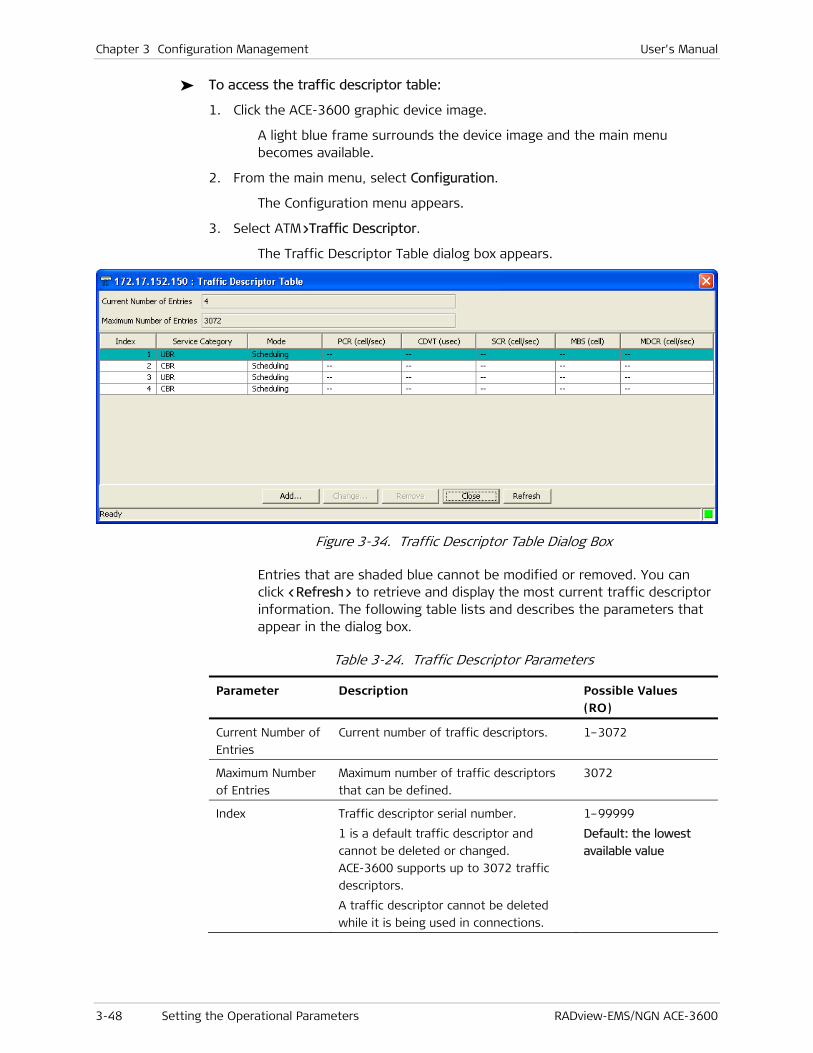
Chapter 3 Configuration Management User's Manual
3-48 Setting the Operational Parameters RADview-EMS/NGN ACE-3600
To access the traffic descriptor table:
1. Click the ACE-3600 graphic device image.
A light blue frame surrounds the device image and the main menu becomes available.
2. From the main menu, select Configuration.
The Configuration menu appears.
3. Select ATM>Traffic Descriptor.
The Traffic Descriptor Table dialog box appears.
Figure 3-34. Traffic Descriptor Table Dialog Box
Entries that are shaded blue cannot be modified or removed. You can click <Refresh> to retrieve and display the most current traffic descriptor information. The following table lists and describes the parameters that appear in the dialog box.
Table 3-24. Traffic Descriptor Parameters
Parameter Description Possible Values (RO)
Current Number of
Entries
Current number of traffic descriptors. 1–3072
Maximum Number
of Entries
Maximum number of traffic descriptors
that can be defined.
3072
Index Traffic descriptor serial number.
1 is a default traffic descriptor and
cannot be deleted or changed.
ACE-3600 supports up to 3072 traffic
descriptors.
A traffic descriptor cannot be deleted
while it is being used in connections.
1–99999
Default: the lowest
available value

User's Manual Chapter 3 Configuration Management
RADview-EMS/NGN ACE-3600 Setting the Operational Parameters 3-49
Parameter Description Possible Values (RO)
Service Category The service category for the currently
configured traffic descriptor.
The service category is selectable only
when creating a traffic descriptor; not
for existing traffic descriptors.
CBR
VBR1
VBR2
VBR3
UBR
UBR1
UBR2
UBR+
Default: UBR
Mode Determines the mode of the traffic
descriptor.
The Policing mode cannot be changed or
configured for UBR service category.
Scheduling mode cannot be configured
for VBR1 and UBR+ service categories.
Scheduling
Scheduling & Shaping
Policing
Default: Scheduling
PCR (cell/sec) Peak Cell Rate in cells per second.
PCR cannot be changed while a VP or VC
XC is using it.
For scheduling mode, this parameter is
set to 0.
100–353208
Default: 100
CDVT (μsec) Cell Delay Variation Tolerance in μsec.
CDVT cannot be changed while VP or VC
XC is using CDVT.
For scheduling mode, this parameter is
set to 0.
1–80000
Default: 1
SCR (cell/sec) Sustainable Cell Rate in cells per second.
SCR cannot be changed while VP or VC
XC is using it.
For scheduling mode, this parameter is
set to 0.
100–353208
Must be smaller than
PCR
Default: 100
MBS (cell) Max Burst Size in cells.
MBS cannot be changed while VP or VC
XC uses PCR.
For scheduling mode, this parameter is
set to 0.
1–8388608
Default: 1
MBS (cell/sec) Max Burst Size in cells.
MBS cannot be changed while VP or VC
XC uses PCR.
For scheduling mode, this parameter is
set to 0.
1–8388608
Default: 1
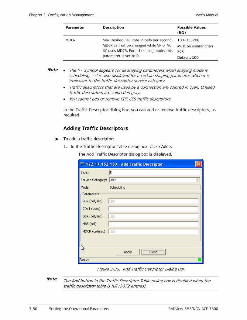
Chapter 3 Configuration Management User's Manual
3-50 Setting the Operational Parameters RADview-EMS/NGN ACE-3600
Parameter Description Possible Values (RO)
MDCR Max Desired Cell Rate in cells per second.
MDCR cannot be changed while VP or VC
XC uses MDCR. For scheduling mode, this
parameter is set to 0.
100–353208
Must be smaller than
PCR
Default: 100
• The ‘--‘ symbol appears for all shaping parameters when shaping mode is scheduling. ‘--‘ is also displayed for a certain shaping parameter when it is irrelevant to the traffic descriptor service category.
• Traffic descriptors that are used by a connection are colored in cyan. Unused traffic descriptors are colored in gray.
• You cannot add or remove CBR CES traffic descriptors.
In the Traffic Descriptor dialog box, you can add or remove traffic descriptors, as required.
Adding Traffic Descriptors
To add a traffic descriptor:
1. In the Traffic Descriptor Table dialog box, click <Add>.
The Add Traffic Descriptor dialog box is displayed.
Figure 3-35. Add Traffic Descriptor Dialog Box
The Add button in the Traffic Descriptor Table dialog box is disabled when the traffic descriptor table is full (3072 entries).
Note
Note

User's Manual Chapter 3 Configuration Management
RADview-EMS/NGN ACE-3600 Setting the Operational Parameters 3-51
2. Enter the required parameters in the editable fields (see Table 3-25), and then click <Apply>.
The system validates the new traffic descriptor (see Traffic Descriptor Validation). Once validated, the traffic descriptor is added to the table.
Table 3-25. Add Traffic Descriptor Parameters
Parameter Description Possible Values (RW)
Index The traffic descriptor serial number.
ACE-3600 supports up to 3072 traffic
descriptors.
1–99999
Default: The lowest
available value
Service Category The service category for the currently
configured traffic descriptor.
CBR
VBR1
VBR2
VBR3
UBR
UBR1
UBR2
UBR+
Default: UBR
Mode Determines the mode of the traffic
descriptor.
The Policing mode cannot be changed
or configured for UBR service category.
Scheduling mode cannot be configured
for VBR1 and UBR+ service categories.
Scheduling
Scheduling & Shaping
Policing
Default: Scheduling
PCR (cell/sec) Peak Cell Rate in cells per second.
For scheduling mode, this parameter is
set to 0.
100–353208
(Read/Write – if a mode
other than Scheduling is
selected)
CVDT (cell/μsec) Cell Delay Variation Tolerance in μsec.
For scheduling mode, this parameter is
set to 0.
1–80000
(Read/Write – if a mode
other than Scheduling is
selected)
SCR (cell/sec) Sustainable Cell Rate in cells per
second.
For scheduling mode, this parameter is
set to 0.
100–353208
Must be smaller than
PCR
(Read/Write – if a mode
other than Scheduling is
selected)
MBS (cell) Max Burst Size in cells.
For scheduling mode, this parameter is
set to 0.
1–8388608
(Read/Write – if a mode
other than Scheduling is
selected)

Chapter 3 Configuration Management User's Manual
3-52 Setting the Operational Parameters RADview-EMS/NGN ACE-3600
Parameter Description Possible Values (RW)
MDCR (cell/sec) Max Desired Cell Rate in cells.
For scheduling mode, this parameter is
set to 0.
100–353208
Must be smaller than
PCR
(Read/Write – if a mode
other than Scheduling is
selected)
Modifying Traffic Descriptors
To modify a traffic descriptor:
1. In the Traffic Descriptor Table dialog box (see Figure 3-34), select a descriptor, and then click <Change>.
The Change Traffic Descriptor dialog box is displayed.
Figure 3-36. Change Traffic Descriptor Dialog Box
2. Modify the parameters as required in the editable fields (see Table 3-24), and then click <Set>.
The system validates the changes (see Traffic Descriptor Validation), and then displays the Traffic Descriptor Table dialog box (see Figure 3-34), with the updated traffic descriptor.

User's Manual Chapter 3 Configuration Management
RADview-EMS/NGN ACE-3600 Setting the Operational Parameters 3-53
Removing a Traffic Descriptor
To remove a traffic descriptor:
• In the Traffic Descriptor Table dialog box (see Figure 3-34), select the row of the descriptor you want to remove, and then click <Remove>.
The descriptor is removed from the list.
• The Remove button is disabled when no entry is selected or when traffic descriptor number 1 is selected.
• A traffic descriptor cannot be deleted if it is being used by a connection.
Traffic Descriptor Validation
ACE-3600 performs the following traffic descriptor validations:
• Index – Checks whether the traffic descriptor value already exists, and whether its edited value is out of range. If so, an error message appears.
• Number of Entries – Checks whether the table is full (3072 entries). If so, an error message appears.
• Parameters – Checks whether any of the parameters is out of range. If so, an error message appears.
• SCR vs. PCR – Checks whether the SCR is equal to or smaller than the PCR. If not, an error message appears.
• PCR vs. MDCR – Checks whether the MDCR is smaller or equal to the PCR. If not, an error message appears.
• MDCR vs. PCR-100 – Checks whether the MDCR value is lower than the PCR-100 value. If not, an error message appears.
Configuring OAM
The OAM configuration consists of:
• Configuring OAM Loopback Parameters
• Configuring OAM Descriptors.
Configuring OAM Loopback Parameters
The OAM loopback function allows ACE-3600 to send OAM loopback cells in case of a link failure. The OAM Parameters dialog box allows you to define the loopback source address and failure threshold.
To configure OAM parameters:
1. Click the ACE-3600 graphic device image.
A light blue frame surrounds the device image and the main menu becomes available.
2. From the main menu, select Configuration.
Note

Chapter 3 Configuration Management User's Manual
3-54 Setting the Operational Parameters RADview-EMS/NGN ACE-3600
The Configuration menu appears.
3. From the Configuration menu, select ATM>OAM Parameters.
The OAM Parameters dialog appears.
Figure 3-37. OAM Parameters Dialog Box
You can click <Refresh> to retrieve and display the most current OAM parameter information. Table 3-26 lists and describes the parameters that appear in the dialog box.
Table 3-26. OAM Parameters
Parameter Description Possible Values (RW)
Loopback Source
Address (hex)
The address of the loopback
source.
00 – FF x 16 (Hex)
Default: 00 00 … 01
Loopback Failure
Threshold
The number of loopback cells which
must be lost, to declare a loopback
failure.
1 – 16
Default: 1
Configuring OAM Descriptors
You can define up to 256 OAM descriptors, which can be set to work in End-to-End, Segment, or Intermediate mode. Each descriptor's continuity check direction can be set accordingly.
The OAM Descriptor Table dialog box allows you to configure OAM descriptors for later use by different connections.
To view the currently defined OAM descriptors:
1. Click the ACE-3600 graphic device image.
A light blue frame surrounds the device image and the main menu becomes available.
2. From the main menu, select Configuration.
The Configuration menu appears.
3. From the Configuration menu, select ATM>OAM Descriptor.
The OAM Descriptor Table dialog box appears.
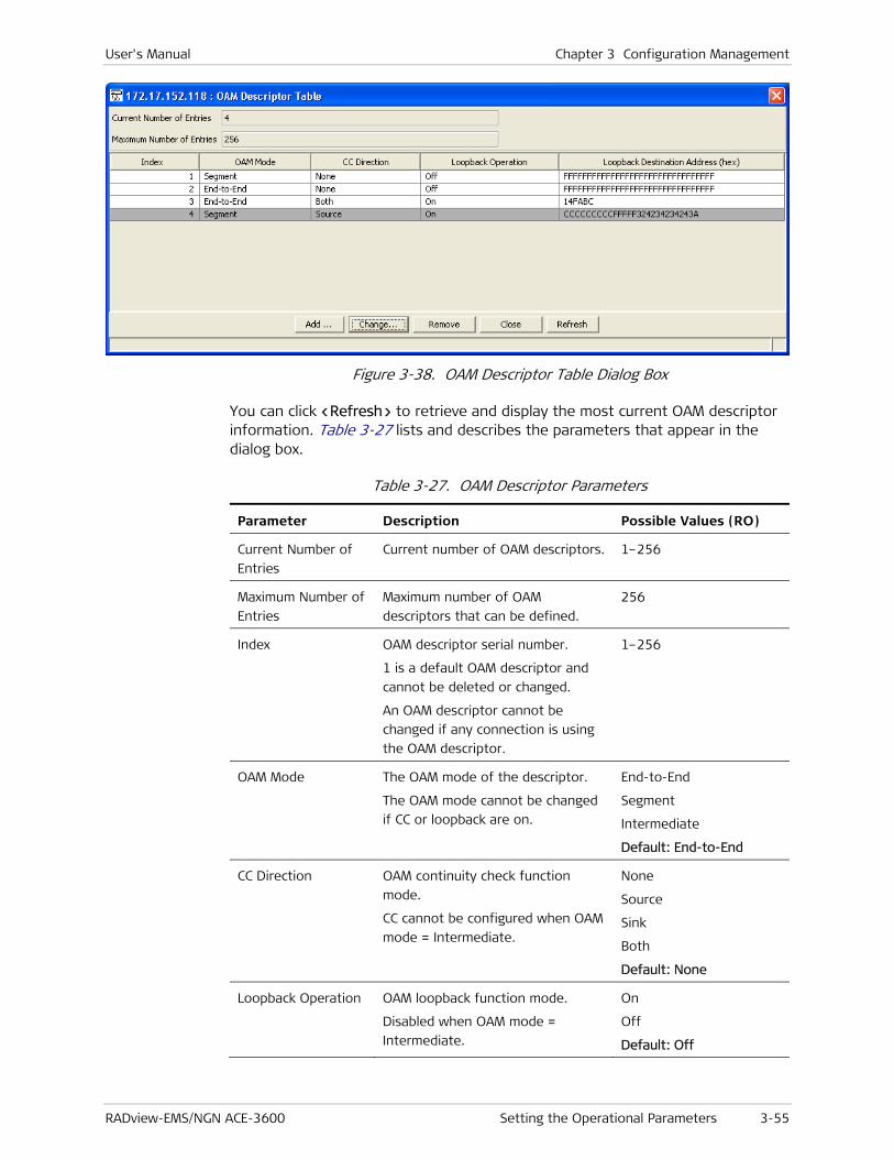
User's Manual Chapter 3 Configuration Management
RADview-EMS/NGN ACE-3600 Setting the Operational Parameters 3-55
Figure 3-38. OAM Descriptor Table Dialog Box
You can click <Refresh> to retrieve and display the most current OAM descriptor information. Table 3-27 lists and describes the parameters that appear in the dialog box.
Table 3-27. OAM Descriptor Parameters
Parameter Description Possible Values (RO)
Current Number of
Entries
Current number of OAM descriptors. 1–256
Maximum Number of
Entries
Maximum number of OAM
descriptors that can be defined.
256
Index
OAM descriptor serial number.
1 is a default OAM descriptor and
cannot be deleted or changed.
An OAM descriptor cannot be
changed if any connection is using
the OAM descriptor.
1–256
OAM Mode The OAM mode of the descriptor.
The OAM mode cannot be changed
if CC or loopback are on.
End-to-End
Segment
Intermediate
Default: End-to-End
CC Direction OAM continuity check function
mode.
CC cannot be configured when OAM
mode = Intermediate.
None
Source
Sink
Both
Default: None
Loopback Operation OAM loopback function mode.
Disabled when OAM mode =
Intermediate.
On
Off
Default: Off

Chapter 3 Configuration Management User's Manual
3-56 Setting the Operational Parameters RADview-EMS/NGN ACE-3600
Parameter Description Possible Values (RO)
Loopback
Destination Address
(hex)
The OAM loopback address that is
transmitted on each OAM loopback
cell.
Enabled only when Loopback
Operation = On.
String of 16 bytes, Hex
Default: FF FF … FF
• OAM descriptors that are used by a connection are colored in cyan. Unused descriptors are colored in gray.
• An OAM descriptor cannot be modified or removed when it is being used by connections.
Adding an OAM Descriptor
You can add or remove OAM descriptors from the OAM Descriptor Table, as required.
To add an OAM descriptor:
1. In the OAM Descriptor Table dialog box (see Figure 3-38), click <Add>.
The Add OAM Descriptor dialog box appears.
Figure 3-39. Add OAM Descriptor Dialog Box
The Add button in the OAM Descriptor Table dialog box is disabled when the OAM Descriptor Table is full (256 entries).
2. Enter the required parameters in the editable fields (see Table 3-28), and then click <Apply>.
The system validates the new OAM descriptor (see OAM Descriptor Validation). Once validated, it is added to the table.
Note
Note
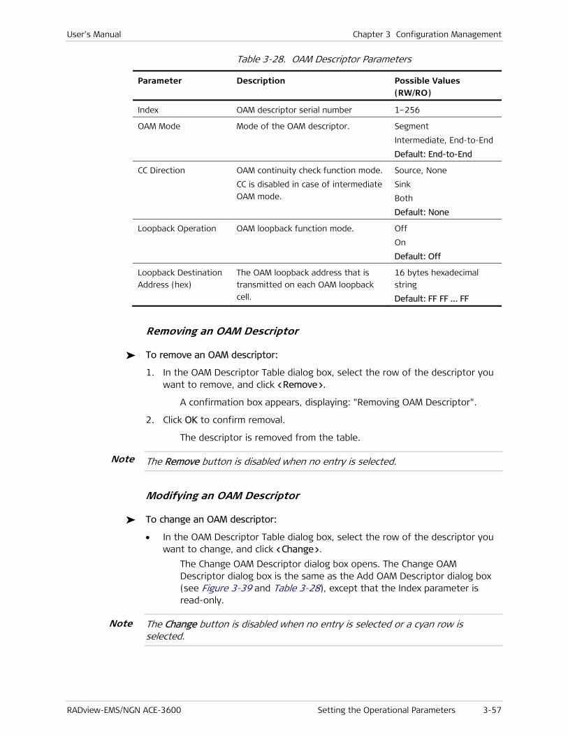
User's Manual Chapter 3 Configuration Management
RADview-EMS/NGN ACE-3600 Setting the Operational Parameters 3-57
Table 3-28. OAM Descriptor Parameters
Parameter Description Possible Values (RW/RO)
Index OAM descriptor serial number 1–256
OAM Mode Mode of the OAM descriptor.
Segment
Intermediate, End-to-End
Default: End-to-End
CC Direction OAM continuity check function mode.
CC is disabled in case of intermediate
OAM mode.
Source, None
Sink
Both
Default: None
Loopback Operation OAM loopback function mode. Off
On
Default: Off
Loopback Destination
Address (hex)
The OAM loopback address that is
transmitted on each OAM loopback
cell.
16 bytes hexadecimal
string
Default: FF FF … FF
Removing an OAM Descriptor
To remove an OAM descriptor:
1. In the OAM Descriptor Table dialog box, select the row of the descriptor you want to remove, and click <Remove>.
A confirmation box appears, displaying: "Removing OAM Descriptor".
2. Click OK to confirm removal.
The descriptor is removed from the table.
The Remove button is disabled when no entry is selected.
Modifying an OAM Descriptor
To change an OAM descriptor:
• In the OAM Descriptor Table dialog box, select the row of the descriptor you want to change, and click <Change>.
The Change OAM Descriptor dialog box opens. The Change OAM Descriptor dialog box is the same as the Add OAM Descriptor dialog box (see Figure 3-39 and Table 3-28), except that the Index parameter is read-only.
The Change button is disabled when no entry is selected or a cyan row is selected.
Note
Note
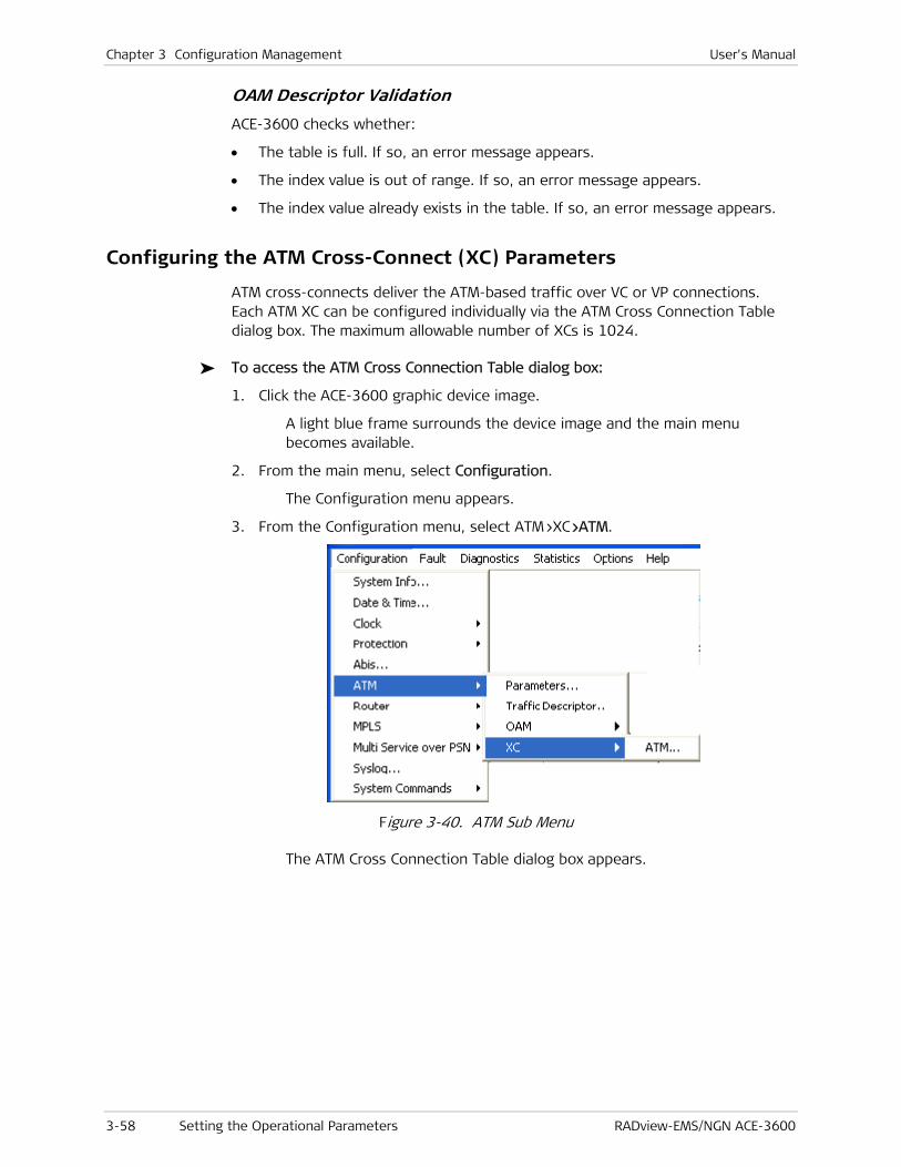
Chapter 3 Configuration Management User's Manual
3-58 Setting the Operational Parameters RADview-EMS/NGN ACE-3600
OAM Descriptor Validation
ACE-3600 checks whether:
• The table is full. If so, an error message appears.
• The index value is out of range. If so, an error message appears.
• The index value already exists in the table. If so, an error message appears.
Configuring the ATM Cross-Connect (XC) Parameters
ATM cross-connects deliver the ATM-based traffic over VC or VP connections. Each ATM XC can be configured individually via the ATM Cross Connection Table dialog box. The maximum allowable number of XCs is 1024.
To access the ATM Cross Connection Table dialog box:
1. Click the ACE-3600 graphic device image.
A light blue frame surrounds the device image and the main menu becomes available.
2. From the main menu, select Configuration.
The Configuration menu appears.
3. From the Configuration menu, select ATM>XC>ATM.
Figure 3-40. ATM Sub Menu
The ATM Cross Connection Table dialog box appears.

User's Manual Chapter 3 Configuration Management
RADview-EMS/NGN ACE-3600 Setting the Operational Parameters 3-59
Figure 3-41. ATM Cross Connection Table Dialog Box
Table 3-29. ATM Cross Connection Table Parameters
Parameter Description Possible Values (RO)
Current Number of
Connections
Current number of defined XCs. 0–1024
Maximum Number of
Connections
Maximum number of XCs that can be
defined.
1024
XC ID
Unique string that identifies the XC. Up to 9 alphanumeric
characters, case-
sensitive
Default: blank
EP-1 Port The endpoint’s (1) port type and mode. ATM-155 1–4
EP-1 VPI The endpoint’s (1) VPI.
The VP/VC XC configuration should
comply with the following rules:
• Two VP XCs with the same VPI cannot
be configured on the same port.
• Two VC XCs with the same VPI/VCI
cannot be configured on the same
port.
• VPI/VCI cannot be changed on-the-fly
(dynamically).
0–255
EP-1 VCI The endpoint’s (1) VCI for VC XC.
The field is disabled when
XC Type = “VP”.
The VC XC configuration should comply
with the same rules defined above for
the EP-1 VPI.
32–65535
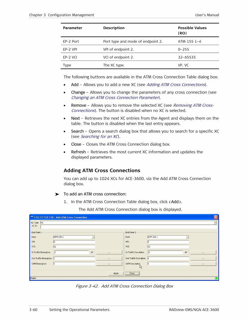
Chapter 3 Configuration Management User's Manual
3-60 Setting the Operational Parameters RADview-EMS/NGN ACE-3600
Parameter Description Possible Values (RO)
EP-2 Port Port type and mode of endpoint 2. ATM-155 1–4
EP-2 VPI VPI of endpoint 2. 0–255
EP-2 VCI VCI of endpoint 2. 32–65535
Type The XC type. VP, VC
The following buttons are available in the ATM Cross Connection Table dialog box:
• Add – Allows you to add a new XC (see Adding ATM Cross Connections).
• Change – Allows you to change the parameters of any cross connection (see Changing an ATM Cross Connection Parameter).
• Remove – Allows you to remove the selected XC (see Removing ATM Cross-Connections). The button is disabled when no XC is selected.
• Next – Retrieves the next XC entries from the Agent and displays them on the table. The button is disabled when the last entry appears.
• Search – Opens a search dialog box that allows you to search for a specific XC (see Searching for an XC).
• Close – Closes the ATM Cross Connection dialog box.
• Refresh – Retrieves the most current XC information and updates the displayed parameters.
Adding ATM Cross Connections
You can add up to 1024 XCs for ACE-3600, via the Add ATM Cross Connection dialog box.
To add an ATM cross connection:
1. In the ATM Cross Connection Table dialog box, click <Add>.
The Add ATM Cross Connection dialog box is displayed.
Figure 3-42. Add ATM Cross Connection Dialog Box
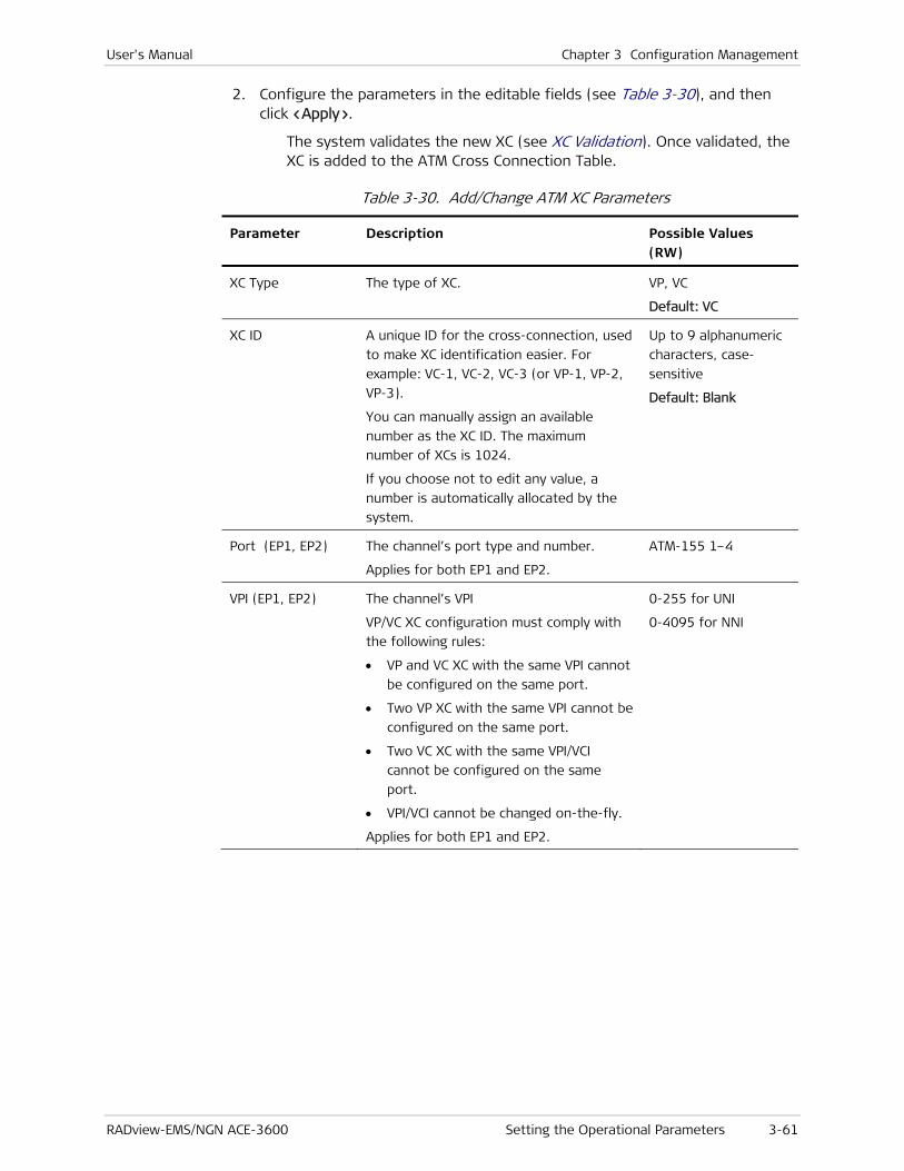
User's Manual Chapter 3 Configuration Management
RADview-EMS/NGN ACE-3600 Setting the Operational Parameters 3-61
2. Configure the parameters in the editable fields (see Table 3-30), and then click <Apply>.
The system validates the new XC (see XC Validation). Once validated, the XC is added to the ATM Cross Connection Table.
Table 3-30. Add/Change ATM XC Parameters
Parameter Description Possible Values (RW)
XC Type The type of XC. VP, VC
Default: VC
XC ID
A unique ID for the cross-connection, used
to make XC identification easier. For
example: VC-1, VC-2, VC-3 (or VP-1, VP-2,
VP-3).
You can manually assign an available
number as the XC ID. The maximum
number of XCs is 1024.
If you choose not to edit any value, a
number is automatically allocated by the
system.
Up to 9 alphanumeric
characters, case-
sensitive
Default: Blank
Port (EP1, EP2) The channel’s port type and number.
Applies for both EP1 and EP2.
ATM-155 1–4
VPI (EP1, EP2)
The channel’s VPI
VP/VC XC configuration must comply with
the following rules:
• VP and VC XC with the same VPI cannot
be configured on the same port.
• Two VP XC with the same VPI cannot be
configured on the same port.
• Two VC XC with the same VPI/VCI
cannot be configured on the same
port.
• VPI/VCI cannot be changed on-the-fly.
Applies for both EP1 and EP2.
0-255 for UNI
0-4095 for NNI

Chapter 3 Configuration Management User's Manual
3-62 Setting the Operational Parameters RADview-EMS/NGN ACE-3600
Parameter Description Possible Values (RW)
VCI (EP1, EP2) The channel’s VCI for VC XC.
Field is disabled when the selected
XC Type = “VP”.
VC XC configuration must comply with the
same rules defined above for the VPI, with
the addition of the following rule:
• When a VP/VC XC configuration uses an
existing VPL/VCL that is not part of a
VP/VC XC, the VPL/VCL should be
modified respectively.
Applies for both EP1 and EP2.
32–65535
In Traffic
Descriptor
(EP1, EP2)
The channel's policing descriptor.
Clicking the […] button opens the Traffic Descriptor Table Dialog Box, enabling
traffic descriptor index selection.
The traffic descriptor must comply with
the following rules:
• It must be created in advance.
• It can be changed after the XC is
created, provided that the XC is of the
same service category and mode.
• When the TD is set to 0 (i.e. In
Checkbox is cleared), the policing for
the selected ATM channel is stopped.
0–99999
Default: 1
In Checkbox When the checkbox is cleared, the In
Traffic Descriptor value is set to 0, and the
policing for the selected ATM channel is
stopped.
Cleared
Selected
Default: Selected
Out Traffic
Descriptor
(EP1, EP2)
The channel's policing descriptor.
Clicking the […] button opens the Traffic
Descriptor dialog box (see Figure 3-34),
enabling traffic descriptor index selection.
The traffic descriptor must comply with
the following rules:
• It must be created in advance.
• It can be changed after the XC is
created, provided that the XC is of the
same service category and mode.
• A CBR-CES category TD cannot be used.
1–99999
Default: 1
User's Manual Chapter 3 Configuration Management
RADview-EMS/NGN ACE-3600 Setting the Operational Parameters 3-63
Parameter Description Possible Values (RW)
OAM Descriptor
(EP1, EP2)
The channel’s OAM descriptor.
Clicking the […] button opens the OAM
Descriptor Table dialog box (see Figure 3-38) enabling OAM Descriptor index
selection.
The OAM descriptor must comply with the
following rules:
• It must be created in advance.
• Its mode cannot be set to end-to-end.
• The maximum number of endpoints
(VCL/VPL) with an OAM descriptor and
OAM Loopback is 128.
1–256 (max XC * 2)
Default: 1
The maximum number of VPI/VCIs with Loopback Operation set to On is 128.
XC Validation
ACE-3600 checks whether:
• The table is full. If so, the Apply button is disabled and no XC can be added.
• The ranges of the VPI, VCI, In/Out traffic descriptors, and OAM descriptors (for both EP1 and EP2) are within the acceptable range. If a parameter is found to be out of range, an appropriate error message appears.
• The XC ID has a unique value. If not, an error message appears.
• The Port value of both endpoints is different. If not, an error message appears.
• There are VCLs with the same VPI. If so, an error message appears.
• There are VCLs with the same VPI/VCI. If so, an error message appears.
• Traffic descriptors are defined for both endpoints. If not, an error message appears.
• An OAM descriptor exists for both endpoints. If an OAM descriptor is missing, an error message appears.
Changing an ATM Cross Connection Parameter
You can change any cross connection parameter, via the ATM Cross Connection Parameters dialog box.
To change the ATM XC parameters:
1. In the ATM Cross Connection Table dialog box (see Figure 3-41), select the row of the XC for which you want to display details, and then click <Change>.
The Change ATM Cross Connection Parameters dialog box appears.
Note

Chapter 3 Configuration Management User's Manual
3-64 Setting the Operational Parameters RADview-EMS/NGN ACE-3600
2. Modify the parameters in the editable fields (see Table 3-30), as required, and then click <Apply>.
The system validates the new XC (see XC Validation). Once validated, the XC is updated and displayed in the ATM Cross Connection Table.
Removing ATM Cross-Connections
To remove an ATM cross connection:
1. In the ATM Cross Connection Table dialog box (see Figure 3-41), select the cross connection you want to remove.
2. Click <Remove>.
A confirmation-box appears, displaying: “Removing ATM XC.”
3. Click <OK> to confirm removal.
The cross connection is removed.
Searching for an XC
To search for an ATM cross connection:
1. In the ATM Cross Connection Table dialog box (see Figure 3-41), click <Search>.
The Search XCs dialog box is displayed.
Figure 3-43. Search XCs Dialog Box
2. In Start From XC ID, type the ID of the XC that you want to display at the top of the ATM Cross Connection table, and then click <Set>.
The ATM Cross Connection table appears, with entries starting from the selected XC ID.
Configuring the Router
The router functionality allows ACE-3600 to establish an IP link with the management station(s), and also allows management traffic to be carried transparently through the unit towards specified targets, over pseudowire connections or other channels.
The router configuration includes three stages:
• Configuring the Router Parameters

User's Manual Chapter 3 Configuration Management
RADview-EMS/NGN ACE-3600 Setting the Operational Parameters 3-65
• Configuring the Router Interface
• Setting the Static Route Parameters.
Configuring the Router Parameters
To set the router parameters:
1. From the Configurations menu, select Router>Parameters.
The Router Parameters dialog box is displayed.
Figure 3-44. Router Parameters Dialog Box
Table 3-31. Router Parameters
Parameter Description Possible Values (RO/RW)
System Address The unique IP address that represents this
ACE-3600 unit (does not represent an IP
subnet).
Note:
• This IP address cannot be included in the subnet of one of the interfaces.
• This field cannot be changed (i.e. is read only) when its value is other than 0.0.0.0 AND is the same as the LDP ID address (see LDP Parameters).
0.0.0.0 –
255.255.255.255 (any
valid IP address)
Default Gateway: The default gateway input is enabled only
when the Router Interface is Ethernet.
Router Interface Select from predefined router interfaces
(see Configuring the Router Interface).

Chapter 3 Configuration Management User's Manual
3-66 Setting the Operational Parameters RADview-EMS/NGN ACE-3600
Parameter Description Possible Values (RO/RW)
IP Address The unique IP address that represents this
ACE-3600 unit (does not represent an IP
subnet).
Note:
• This IP address cannot be included in the subnet of one of the interfaces.
• This field cannot be changed (i.e. is read only) when its value is other than 0.0.0.0 AND is the same as the LDP ID address.
0.0.0.0 –
255.255.255.255 (any
legal IP address)
ARP Aging Time The period in seconds that must pass
before ARP entries are discarded.
300–100000
Default: 1200
2. Modify the parameters in the editable fields as required, and then click <Set>.
The router parameters are assigned the given values.
Configuring the Router Interface
Each required router interface is configured individually and includes various parameters as described below.
To configure the router interface:
1. From the main menu, select <Configuration>.
The Configuration menu appears.
.
Figure 3-45. Configuration Menu
2. From the Configuration menu, select Router>Interface.
The Router Interfaces Table dialog box is displayed.

User's Manual Chapter 3 Configuration Management
RADview-EMS/NGN ACE-3600 Setting the Operational Parameters 3-67
Figure 3-46. Router Interfaces Table Dialog Box
Table 3-32. Router Interfaces Table Parameters
Parameter Description Possible Values
Current Number
of Entries
Current number of router interfaces defined
in the table.
0 – 1024
Maximum
Number of
Entries
Maximum number of router interfaces that
can be defined.
1024
Number Unique ID number of the router interface
which has its details displayed.
1–1024
Name An optional name that describes this
interface (does not have to be a unique
name).
Up to 32 alphanumeric
characters;
case-sensitive
IP Address IP address of the router interface. 0.0.0.0 –
255.255.255.255 (any
Chapter 3 Configuration Management User's Manual
3-68 Setting the Operational Parameters RADview-EMS/NGN ACE-3600
Parameter Description Possible Values
Note:
• For PPPoE interface type (see below), 0.0.0.0 must be used to indicate that the IP is allocated dynamically by the PPP session.
• The IP address cannot be included in the subnet of one of the configured interfaces.
legal IP address)
Default: 0.0.0.0
IP Mask Subnet mask of the router interface.
Note: The IP mask address should always be a sequence of all ones. It cannot include gaps or zeros in between.
0.0.0.0 –
255.255.255.255 (any
legal IP mask)
Bound To
The router interface type and the number of
the specific port or PW that is used for the
router interface.
GbE1, GbE2 (for port
type Gigabit Ethernet)
MNG-ETH (for port
type Ethernet)
ETH Rdn Group <Port>
(example: ETH Rdn
Group 1)
ATM-155 1-4
(<VPI>/<VCI>)
VCL Interface
<Port>(<VPI>/<VCI>)
PW <PW number>
PPPoE<PPPoE ID)
(example: PPPoE 2)
GRE
Default: GbE 1
Management
Access
Enable or disable management access (SNMP,
Telnet, SSH, Web, SSL) via this router
interface.
Enable
Disable
Default: Enable
Adding a Router Interface
To add a router interface:
• In the Router Interfaces Table dialog box (see Figure 3-46), click <Add>.
The Add Router Interface dialog box appears.

User's Manual Chapter 3 Configuration Management
RADview-EMS/NGN ACE-3600 Setting the Operational Parameters 3-69
Figure 3-47. Add Router Interface Dialog Box
Table 3-33. Add Router Interface Parameters
Parameter Description Possible Values
Number Unique ID number of the router interface
which has its details displayed.
1–1024
Name An optional name that describes this
interface (does not have to be a unique
name).
Up to 32 alphanumeric
characters;
case-sensitive
Bound To Type The router interface type. Port
Port ETH
Port ETH Rdn Group
VCL Interface
PW
PPPoE
GRE
Default: Port
Bound To Port The number of the specific port or PW that is
used for the router interface, according to
the selected Bound To Type (see above).
ATM-155 1-4
<Port ETH number>
<Port ETH Rdn Group

Chapter 3 Configuration Management User's Manual
3-70 Setting the Operational Parameters RADview-EMS/NGN ACE-3600
Parameter Description Possible Values
Note:
• The PW interface type is available only if the PSN license is installed and a PW connection with an appropriate type exists.
• An Ethernet group is available only if it was previously created.
• If the router interface is bounded to an ATM VC, check whether the maximum number of XCs has been reached.
• Only PW of type AAL5-SDU with router termination type can be selected (must be previously defined).
• The Ethernet port cannot be selected when it belongs to a redundancy group.
• This field is enabled only if Bound to Type
is "Port".
number>
GbE 1, GbE 2
MNG-ETH
GRE
Default: GbE 1
Bound To VPI VPI of the PVC connected to the host
interface.
Not available if Ethernet port type was
selected.
Enabled only when Port is enabled with value
other than “ETH” or “ETH Rdn Group”.
Note: A router interface with the same VPI as an existing VP XC on the same port, cannot be configured.
0–255 for UNI
(max VPI bits is 8)
0–4095 for NNI
(max VPI bits is 12)
Default: 0
Bound To VCI VCI of the PVC connected to the router
interface.
Not available for Ethernet, Ethernet group,
and PW interface types.
Enabled only when Port is enabled with value
other than “ETH” or “ETH Rdn Group”.
Note: A router interface with the same VPI/VCI as an existing VC XC on the same port, cannot be configured.
32–65535
Default: 32
Bound To PW Parameter is enabled only when selected
Type = “PW”. When it is enabled, you can
click … to display the PW Table dialog box.
IP Address IP address of the router interface. Parameter
is disabled when selected Type = “PPPoE”.
Note:
• The IP address cannot be included in the subnet of one of the configured
0.0.0.0 –
255.255.255.255 (any
legal IP address)
Default: 0.0.0.0
User's Manual Chapter 3 Configuration Management
RADview-EMS/NGN ACE-3600 Setting the Operational Parameters 3-71
Parameter Description Possible Values
interfaces.
IP Mask Subnet mask of the router interface. The
parameter is disabled when selected Type =
“PPPoE”.
Note: The IP mask address should always be a sequence of all ones. It cannot include gaps or zeros in between.
0.0.0.0 –
255.255.255.255 (any
legal IP mask)
Out Traffic
Descriptor
Traffic descriptor of the PVC connected to the
router interface.
Enabled only when Port is enabled with value
other than “ETH” or “ETH Rdn Group”.
The Out Traffic Descriptor is disabled when
selected Type = “VCL Interface".
When it is enabled, you can click … to display
the Out Traffic Descriptor dialog box.
Note:
• A traffic descriptor (TD) must be configured before it can appear on the menu.
• The descriptor's rate cannot be higher than the port's output rate.
• A TD with the CBR-CES service category cannot be used.
1–99999
Default: 1
OAM Descriptor
OAM descriptor of the PVC connected to the
host interface.
Enabled only when Port is enabled with value
other than “ETH” or “ETH Rdn Group”.
The OAM Descriptor is disabled when
selected Type = “VCL Interface".
When it is enabled, you can click … to display
the OAM Descriptor dialog box.
Note: An OAM descriptor (OD) must be configured before it can appear on the menu and it must be defined as end-to-end or segment.
1–256
Default: 2
LLC/SNAP
Encapsulation
The LLC SNAP encapsulation type.
The LLC/SNAP Encapsulation is disabled when:
• Type = “Port” AND Port = “ETH” or “ETH
Rdn Group”
• Type = “PW” or “PPPoE”.
When enabled, the displayed value of
LLC/SNAP Encapsulation is:
• “Bridged PDU”, if Type = “VCL Interface”.
Bridged PDU
Routed PDU
Default: Routed PDU

Chapter 3 Configuration Management User's Manual
3-72 Setting the Operational Parameters RADview-EMS/NGN ACE-3600
Parameter Description Possible Values
• “Routed PDU”, for all other types.
VLAN Tagging Indicates whether a VLAN tag is to be
inserted into the TX (receive) frames. This parameter is enabled, only when Port is enabled with a value of “ETH” or “ETH Rdn Group” or “VCL Interface”.
Enable
Disable
Default: Disable
VLAN ID Identifies the VLAN that is carried on the
VLAN tag. Available only if VLAN tagging is
enabled (see above).
0–4094
Default: 0
VLAN Priority Indicates the priority bit value of the VLAN
that is carried on the VLAN tag. Available only
if VLAN tagging is enabled (see above).
0–7
Default: 0
Tunnel Source IP
Address
The source IP address of the IP header on
which the GRE is running.
Note:
• The IP address must either be a system address or one of the configured router interfaces. Otherwise, an error message is returned.
• This parameter only appears, if the
interface type is set to GRE.
A valid IP address.
Default: 0.0.0.0
Tunnel
Destination IP
Address
The destination IP address of the layer on
which the GRE is running.
Note:
• The IP address must be associated with a known route. Otherwise, an error message is returned.
• This parameter only appears if the interface type is set to GRE.
A valid IP address.
Default: 0.0.0.0
Management
Access
Enable or disable management access (SNMP,
Telnet, SSH, Web, SSL) via this router
interface.
Enable
Disable
Default: Enable
• All router interface parameters, with the exception of 'Management Access', cannot be changed dynamically (on-the-fly).
• The number of router interfaces is limited to 20.
• The maximum number of PW type router interfaces is 2.
Setting the Static Route Parameters
For remote manager IPs and peers that are located in a subnet different than that of the router interface, you need to assign static route parameters.
Note

User's Manual Chapter 3 Configuration Management
RADview-EMS/NGN ACE-3600 Setting the Operational Parameters 3-73
To access the static route parameters:
• From the Configuration menu, select Router>Routing.
The Routing Table dialog box is displayed.
Figure 3-48. Routing Table Dialog Box
Adding a Static Route
To add a static route to the Routing table:
1. In the Routing Table dialog box, click <Add Static>.
The Add Static Entry dialog box is displayed.

Chapter 3 Configuration Management User's Manual
3-74 Setting the Operational Parameters RADview-EMS/NGN ACE-3600
Figure 3-49. Add Static Entry Dialog Box
2. Configure the parameters as required, and then click <Apply>.
The newly created static entry is added to the Routing table (see Figure 3-48).
Table 3-34. Add Static Entry Parameters
Parameter Description Possible Values
IP Address IP address of the static route subnet or
station.
It is possible to enter a multicast address
to support multicast clock distribution.
0.0.0.0 –
255.255.255.255
(any legal IP address)
IP Mask IP mask of the static route subnet. 0.0.0.0 –
255.255.255.255
(any legal IP mask)
Next Hop
IP Address
IP address of the next hop. Must belong to
the router interface subnet.
Note:
• Multicast, broadcast, or all ones address is not allowed.
• All zeros cannot be assigned to an address part that is not the router interface's subnet.
• If 0.0.0.0 is used, it indicates that the routing is based on the next hop interface number. This kind of setting is useful when the router interface is of an ATM VC or PW.
0.0.0.0 –
255.255.255.255
Default: 0.0.0.0
Next Hop Router
Interface Number
ID number of the router interface towards
which the destination subnet should be
routed.
Available only if the next hop is 0.0.0.0.
A number of a
previously configured
router interface.
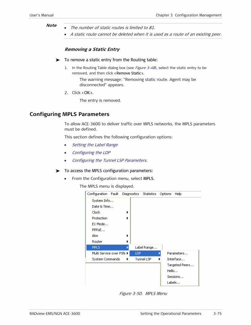
User's Manual Chapter 3 Configuration Management
RADview-EMS/NGN ACE-3600 Setting the Operational Parameters 3-75
• The number of static routes is limited to 81.
• A static route cannot be deleted when it is used as a route of an existing peer.
Removing a Static Entry
To remove a static entry from the Routing table:
1. In the Routing Table dialog box (see Figure 3-48), select the static entry to be
removed, and then click <Remove Static>.
The warning message: "Removing static route. Agent may be disconnected" appears.
2. Click <OK>.
The entry is removed.
Configuring MPLS Parameters
To allow ACE-3600 to deliver traffic over MPLS networks, the MPLS parameters must be defined.
This section defines the following configuration options:
• Setting the Label Range
• Configuring the LDP
• Configuring the Tunnel LSP Parameters.
To access the MPLS configuration parameters:
• From the Configuration menu, select MPLS.
The MPLS menu is displayed.
Figure 3-50. MPLS Menu
Note

Chapter 3 Configuration Management User's Manual
3-76 Setting the Operational Parameters RADview-EMS/NGN ACE-3600
Setting the Label Range
You can configure the range of local labels available for use on packet interfaces. The label range that you set is used by all MPLS applications that allocate local labels for dynamic label switching, MPLS traffic engineering, MPLS VPNs, and so on.
If you set a new label range that does not overlap the range currently in use, the new range does not take effect until the router is reloaded again
To set the label range:
1. From the Configuration menu, select MPLS>Label Range.
The MPLS Parameters dialog box opens.
Figure 3-51. MPLS Parameters Dialog Box
Table 3-35. MPLS Parameters
Parameter Description Possible Values
Dynamic Range Indicates whether the label range is dynamic. Checkbox selected
Checkbox cleared
Default: Checkbox
selected
Lowest Label,
Highest Label
Range of the MPLS ,label. Relevant only for
the incoming direction and has no effect on
the outgoing direction.
Note:
• Cannot be changed when the LDP signaling protocol is enabled.
• The range setting is rejected if there are static PW connections or tunnels configured with labels that are included in the dynamic range.
10000–14095
16–65534 for
dynamic labels only
0–0 when the
dynamic range is not
set
Default:
10000–14095
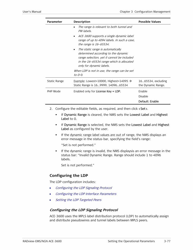
User's Manual Chapter 3 Configuration Management
RADview-EMS/NGN ACE-3600 Setting the Operational Parameters 3-77
Parameter Description Possible Values
• The range is relevant to both tunnel and PW labels.
• ACE-3600 supports a single dynamic label range of up to 4094 labels. In such a case, the range is 16–65534.
• The static range is automatically determined according to the dynamic range selection, yet it cannot be included in the 16–65534 range which is allocated only for dynamic labels.
When LDP is not in use, the range can be set to 0–0
Static Range Example: Lowest=10000, Highest=14095
Static Range is 16…9999, 14096…65534
16…65534, excluding
the Dynamic Range.
PHP Mode Enabled only for License Key = LDP. Enable
Disable
Default: Enable
2. Configure the editable fields, as required, and then click <Set>.
If Dynamic Range is cleared, the NMS sets the Lowest Label and Highest Label to 0.
If Dynamic Range is selected, the NMS sets the Lowest Label and Highest Label as configured by the user.
If the dynamic range label values are out of range, the NMS displays an error-message in the status-bar, specifying the field’s range:
“Set is not performed.”
If the dynamic range is invalid, the NMS displaysis an error message in the status bar: “Invalid Dynamic Range. Range should include 1 to 4096 labels.
Set is not performed.”
Configuring the LDP
The LDP configuration includes:
• Configuring the LDP Signaling Protocol
• Configuring the LDP Interface Parameters
• Setting the LDP Targeted Peers
Configuring the LDP Signaling Protocol
ACE-3600 uses the MPLS label distribution protocol (LDP) to automatically assign and distribute pseudowires and tunnel labels between MPLS peers.

Chapter 3 Configuration Management User's Manual
3-78 Setting the Operational Parameters RADview-EMS/NGN ACE-3600
LDP functionality is available only with a SW license.
To configure the LDP parameters:
1. From the MPLS menu (see Figure 3-50), select LDP>Parameters.
The LDP Parameters dialog box is displayed.
Figure 3-52. LDP Parameters dialog box
Table 3-36. LDP Parameters
Parameter Description Possible Values
LDP ID LDP ID of the local unit.
Can only be changed while Mode is
"disable".
You can select a different LDP ID, as follows:
1. Click the […] button that is adjacent to
the LDP ID field, to display the Router
Interface table.
2. Select an IP address from the Router
Interface table, and then click <Select>.
3. From the Select button sub-menu: select
>Router Interface to display the selected
IP address from the Router Interface
table in the LDP ID field. Or, select
>System Address to display the IP
address of the system address in the
LDP ID field.
IP address format
0.0.0.0 –
255.255.255.255
Mode Indicates whether all LDP operations
performed by the unit are enabled or
disabled.
'Enable' can be selected only if an LDP ID
is defined.
Enable
Disable
Default: Enable
Hello Timer
(sec)
The required interval in seconds between
two consecutive Hello messages. LDP hello
messages enable LDP nodes to discover one
1–65534
Default: 45
Note

User's Manual Chapter 3 Configuration Management
RADview-EMS/NGN ACE-3600 Setting the Operational Parameters 3-79
Parameter Description Possible Values
another and to detect the failure of a
neighbor or of the link to the neighbor.
Hello messages are sent periodically on all
interfaces where LDP is enabled.
The Hello timer cannot be modified while
Mode is "enable", or when LDP interfaces or
targeted peers are defined.
Keep Alive Timer
(sec)
For cases of inactivity, define the time in
seconds after which a Keep Alive message is
sent.
Cannot be modified while Mode is "enable",
or when LDP interfaces or targeted peers
are defined.
1–65534
Default: 40
2. Configure the editable fields, as required (see Table 3-36), and then click <Set>.
If you changed Mode to “Disable”, the NMS displays a confirmation-box: “Changing LDP Mode to ‘Disable’ will close all sessions”, with [OK] and [Cancel] buttons. Click [OK] to continue the Set process.
Set is performed and the parameters have new values.
Set is not performed in the following cases:
• If you entered in LDP ID, an LDP ID that is out of range.
• An error-message is displayed in the status-bar, specifying the field’s range.
• If the value that you selected for LDP ID is not the IP Address of a System Address OR of a Router Interface.
• If another value is selected, the NMS displays an error-message in the status-bar: “LDP ID must be IP Address of the System Address or a Router Interface”.
• If LDP ID or any of the timers were changed while the LDP Mode value is "Disable".
• An error message is displayed: "LDP ID or Timers can be changed only while LDP Mode is ‘Disable'".
Configuring the LDP Interface Parameters
The LDP interface can be referenced to one of the existing router interfaces.
To configure the LDP interface parameters:
1. From the MPLS menu (see Figure 3-50), select LDP>Interface.
The LDP Interface Table dialog box is displayed.
Note
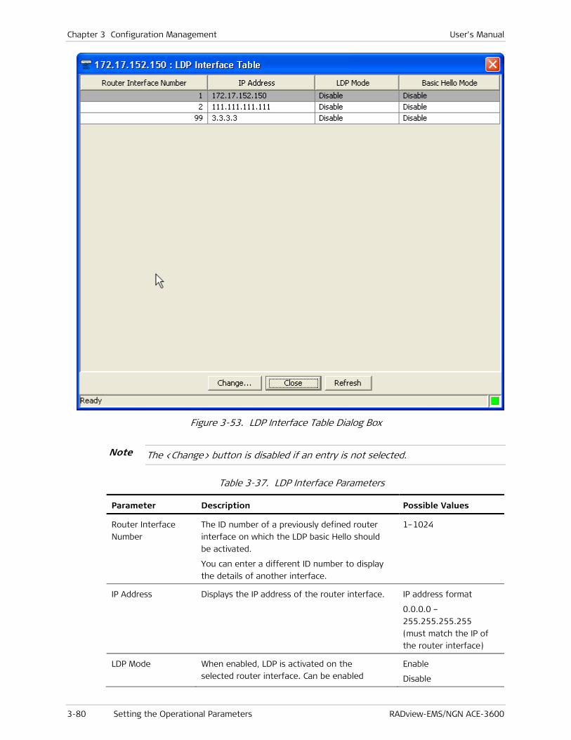
Chapter 3 Configuration Management User's Manual
3-80 Setting the Operational Parameters RADview-EMS/NGN ACE-3600
Figure 3-53. LDP Interface Table Dialog Box
The <Change> button is disabled if an entry is not selected.
Table 3-37. LDP Interface Parameters
Parameter Description Possible Values
Router Interface
Number
The ID number of a previously defined router
interface on which the LDP basic Hello should
be activated.
You can enter a different ID number to display
the details of another interface.
1–1024
IP Address Displays the IP address of the router interface. IP address format
0.0.0.0 –
255.255.255.255
(must match the IP of
the router interface)
LDP Mode When enabled, LDP is activated on the
selected router interface. Can be enabled
Enable
Disable
Note

User's Manual Chapter 3 Configuration Management
RADview-EMS/NGN ACE-3600 Setting the Operational Parameters 3-81
Parameter Description Possible Values
only for Ethernet interfaces.
Basic Hello Mode • Indicates whether basic Hello is activated on
the router interface.
Enable
Disable
2. Select an LDP interface from the table, and then click <Change>.
The Change LDP Interface dialog box is displayed.
Figure 3-54. Change LDP Interface Dialog Box
Table 3-38. Change LDP Interface Parameters
Parameter Description Possible Values
Router Interface
Number
ID number of a previously defined router
interface on which the LDP basic Hello should
be activated.
1–1024 (RO)
IP Address Displays the IP address of the router interface. IP address format
0.0.0.0 –
255.255.255.255
(must match the IP of
the router interface)
LDP Mode When enabled, LDP is activated on the
selected router interface. Can be enabled
only for Ethernet interfaces.
Cannot be changed when the general LDP mode
is disabled.
Enable
Disable
Default: Disable
Basic Hello Mode Select whether basic Hello should be activated
on the router interface. Visible only when LDP
mode is enabled (see above).
Note:
• Should be enabled for every router interface on which LDP basic discovery is enabled.
• There can be only one router interface supporting basic Hello over a single physical
Enable
Disable
Default: Disable
RO when LDP mode is
disabled.

Chapter 3 Configuration Management User's Manual
3-82 Setting the Operational Parameters RADview-EMS/NGN ACE-3600
Parameter Description Possible Values
port.
• Cannot be changed when the general LDP mode is enabled.
3. Configure the editable fields, and then click <Set>.
LDP interface parameters are configured with the new values, unless:
The LDP Mode is changed from “Disable” (to “Enable”) AND the current Router Interface is Bound To “ETH” or “ETH Rdn Group”.
In such a case, the NMS displays an error-message in the status-bar: “LDP Mode cannot be changed while Router Interface is bound to ETH or ETH Rdn Group”.
If the LDP Mode is changed from “Enable” to “Disable”.
A message is displayed: “Failed (possible reason: Targeted Peer is configured on this Router).”
If the Basic Hello Mode is changed from “Disable” to “Enable”.
A message is displayed: “Failed (possible reason: Basic Hello is already enabled on this physical port)".
Setting the LDP Targeted Peers
You can define targeted remote peers with which ACE-3600 should attempt establishing LDP sessions.
To set the targeted peers:
1. From the MPLS menu (see Figure 3-50), select LDP>Targeted Peers.
The LDP Targeted Peer table is displayed.
Figure 3-55. LDP Targeted Peer Table Dialog Box

User's Manual Chapter 3 Configuration Management
RADview-EMS/NGN ACE-3600 Setting the Operational Parameters 3-83
Table 3-39. LDP Targeted Peer Parameters
Parameter Description Possible Values
Current Number of
Entries
Current number of targeted peers defined
in the table.
0 – 1024
Maximum Number
of Entries
Maximum number of targeted peers that
can be defined.
1024
Peer Number ID number of an existing (previously
defined) remote targeted peer. You can
enter a different number to display details
of another peer.
1 - 1024
Peer Name Displays (read only) the name of the
remote targeted peer.
(RO)
IP Address Displays (read-only) the IP address of the
remote targeted peer.
0.0.0.0 –
255.255.255.255
(must match the IP of
the remote peer)
Targeted Mode The targeted peer's functionality. When
enabled, ACE-3600 attempts to create a
targeted LDP session with the peer.
Enable
Disable
Default: Disable
2. Select a peer, and then click <Set Targeted Mode>..
A submenu opens above the button, displaying the options for the targeted mode.
Figure 3-56. Set Targeted Mode Submenu
The <Set Targeted Mode> button is disabled if an entry is not selected.
3. Select 'Enable' or 'Disable'.
A confirmation box displays: “Changing Targeted Mode of selected Peer(s) to <selected value>”.
4. In the confirmation box, click <OK>.
The targeted peer mode is updated in the LDP Targeted Peer table (see Figure 3-55).
Note

Chapter 3 Configuration Management User's Manual
3-84 Setting the Operational Parameters RADview-EMS/NGN ACE-3600
If Mode is changed from “Enable” to “Disable”, and NMS receives an error-msg from the Agent, NMS displays in the status-bar: “Failed (possible reason: Peer is currently used by a LDP PW)". The mode does not change.
Configuring the Tunnel LSP Parameters
LSP tunnels are configured separately in the ingress and egress directions.
Configuring the Ingress Tunnel LSP Parameters
To access the Ingress LSP tunnel parameters:
• From the MPLS menu, select Tunnel LSP> Ingress.
The Ingress LSP Tunnel Table is displayed.
Figure 3-57. Ingress LSP Tunnel Table Dialog Box
To add a new Ingress LSP tunnel:
1. In the Ingress LSP Tunnel Table dialog box, click <Add>.
The Add Ingress LSP Tunnel dialog box is displayed.
Figure 3-58. Add Ingress LSP Tunnel Dialog Box
Note

User's Manual Chapter 3 Configuration Management
RADview-EMS/NGN ACE-3600 Setting the Operational Parameters 3-85
Table 3-40. Ingress LSP Tunnel Parameters
Parameter Description Possible Values
Index ID number of the ingress tunnel. 1–512
Name Name of the ingress tunnel. Up to 32 characters
Default: Tunnel-in
Provisioning
mode
Indicates whether the tunnel assignment
method is manual or LDP assigned.
The provisioning mode cannot be changed
dynamically (on-the-fly).
Manual
LDP
Default: Manual
Label ID of the label. Visible only if the
provisioning mode is set to Manual.
A value within the
static label range
(16–65534)
• When the provisioning mode is set to LDP, a label-binding message with the LDP address is published towards all LDP sessions created locally.
• The label binding message is not published over an LDP session created with targeted peers, meaning that tunnel labels are never created with targeted peers.
• Only one ingress tunnel created by LDP (not manual) is possible.
2. Configure the editable fields, as required, and then click <Apply>.
The new ingress LSP tunnel is added to the Ingress LSP Tunnel table (see Figure 3-57), unless:
The Ingress LSP Tunnel table is full.
Index and Label are out of range. An error-message is displayed in the status-bar, specifying the field’s range.
If the index already exists in the table. An error message is displayed: "Index already exists in Ingress LSP Tunnel Table”.
To change the name and/or label of an Ingress LSP tunnel:
1. In the Ingress LSP Tunnel table (see Figure 3-57), select a tunnel, and then click <Change>.
The Change Ingress LSP Tunnel dialog box is displayed.
Note

Chapter 3 Configuration Management User's Manual
3-86 Setting the Operational Parameters RADview-EMS/NGN ACE-3600
Figure 3-59. Change Ingress LSP Tunnel Dialog Box
2. Change the name and label of the tunnel, as required, and then click <Set>.
The Ingress LSP Tunnel table is updated with these changes.
To remove an Ingress LSP tunnel from the table:
1. In the Ingress LSP Tunnel table (see Figure 3-57), select a tunnel, and then click <Remove>.
A confirmation box appears with the message: “Removing Ingress LSP Tunnel.”
2. Click <OK> to confirm removal.
The tunnel is removed from the Ingress LSP Tunnel table.
Configuring the Egress Tunnel LSP Parameters
To access the egress LSP tunnel parameters:
• From the MPLS menu, select Tunnel LSP> Egress.
The Egress Tunnel LSP table is displayed.
Figure 3-60. Egress LSP Tunnel Table

User's Manual Chapter 3 Configuration Management
RADview-EMS/NGN ACE-3600 Setting the Operational Parameters 3-87
Table 3-41. Egress LSP Tunnel Parameters
Parameter Description Possible Values
Index ID number of the egress tunnel. 1–1024
Name Name of the egress tunnel. Up to 32 characters
Default: Tunnel-out
Provisioning
Mode
Indicates whether the tunnel assignment
method is manual or LDP-assigned.
The provisioning mode cannot be changed
dynamically (on-the-fly).
Manual
LDP
Default: Manual
Peer Number ID number of the remote peer for which
this egress tunnel is created. Visible only if
the provisioning mode is LDP.
An existing peer
number
Label ID of the label. Visible only if the
provisioning mode is set to Manual.
A value within the
static label range
(16–65534)
EXP Bits Mode Indicates how the EXP bits of the tunnel
label are set. If copied from the PW
connection, the EXP bits are copied from
the PSN parameters of the specific PW.
If set as static, the EXP value is set manually
below.
The EXP bits mode cannot be changed
dynamically.
Copy from PW
Static
Default: Copy from PW
EXP Bits The required value for the EXP bits. Visible
only if the EXP bits mode is set to Static.
0–7
To add a new egress LSP tunnel:
1. Click <Add>.
The Add Egress LSP Tunnel dialog box is displayed.

Chapter 3 Configuration Management User's Manual
3-88 Setting the Operational Parameters RADview-EMS/NGN ACE-3600
Figure 3-61. Add Egress LSP Tunnel Dialog Box
2. Configure the editable fields, as required, and then click <Apply>.
The new egress LSP tunnel is added to the egress LSP Tunnel table (see Figure 3-60), unless:
The egress LSP Tunnel table is full.
Index and Label are out of range. An error-message is displayed in the status-bar, specifying the field’s range.
If the index already exists in the table. An error message is displayed: "Index already exists in Egress LSP Tunnel Table”.
To change the name and/or label of an Egress LSP tunnel:
1. In the Egress LSP Tunnel table (see Figure 3-60), select a tunnel, and then click <Change>.
The Change Egress LSP Tunnel dialog box is displayed.

User's Manual Chapter 3 Configuration Management
RADview-EMS/NGN ACE-3600 Setting the Operational Parameters 3-89
Figure 3-62. Change Egress LSP Tunnel Dialog Box
2. Change the name and label of the tunnel, as required, and then click <Set>.
The Egress LSP Tunnel table is updated with these changes.
To remove an Egress LSP tunnel from the table:
1. In the Egress LSP Tunnel table (see Figure 3-60), select a tunnel, and then click <Remove>.
A confirmation box appears with the message: “Removing Egress LSP Tunnel.”
2. Click <OK> to confirm removal.
The tunnel is removed from the Egress LSP Tunnel table.
Configuring Multiservice over PSN Parameters
ACE-3600 is equipped with a Gigabit Ethernet interface for ATM over PSN traffic concentration. Ethernet tunneling parameters are configured via the Multiservice over PSN menu, which provides access to the following tasks:
• Configuring General Multiservice over PSN Parameters
• Defining PSN Peers
• Configuring Pseudowire Connections
To access the Multiservice over PSN options:
• From the Configuration menu, select Multi Service over PSN.
The Multi Service over PSN menu is displayed.

Chapter 3 Configuration Management User's Manual
3-90 Setting the Operational Parameters RADview-EMS/NGN ACE-3600
Figure 3-63. Multi Service over PSN Menu Options
Table 3-42. Multi Service over PSN Menu Options
Menu Option Description Refer to
General Accesses the general Multiservice over PSN
parameters configuration.
Configuring General Multiservice over PSN Parameters
Peer Accesses the peer configuration. Defining PSN Peers
PW Accesses the pseudowire configuration Configuring Pseudowire Connections
View All
Attachment
Circuits
Displays the details of any existing PW
connection.
Configuring the ATM Attachment Circuit Parameters for the PW
Configuring General Multiservice over PSN Parameters
The general parameters include packet misordering and reordering instructions for ATM over PSN traffic.
To configure the ATM parameters:
1. From the Multi Service over PSN menu, select General>ATM.
The ATM Parameters dialog box is displayed.

User's Manual Chapter 3 Configuration Management
RADview-EMS/NGN ACE-3600 Setting the Operational Parameters 3-91
Figure 3-64. Multiservice over PSN - ATM Parameters Dialog Box
2. Configure the editable fields, and then click <Set>.
The ATM parameters are configured.
Table 3-43. ATM Parameters
Parameter Description Possible Values
Misorder Window
Size (packets)
In packet-switched traffic, some packets are not
received according to their predefined sequence
number. This condition is defined as misorder.
Accordingly, this parameter defines the number of
packet windows, in which ACE-3600 tries to fix the
packet sequence misorder errors.
Cannot be changed when PWs exist.
0, 1, 2, 4, 8, 16, 32
Default: 4
Reordering To allow proper de-capsulation of ATM traffic,
ACE-3600 has a mechanism that fixes misorders by
correctly reordering the received packets.
You can enable or disable the reordering
mechanism.
Cannot be changed when PWs exist.
Enable
Disable
Default: Disable
Defining PSN Peers
In a packet-switched network application, ACE-3600 operates opposite remote peer devices, each of which must be defined individually on the Peer menu.
An Ethernet router interface and a default gateway must be configured prior to configuring PSN peers.
To access the Peer menu:
• From the Multi Service over PSN menu, select Peer.
The Peer Table dialog box is displayed.
Note

Chapter 3 Configuration Management User's Manual
3-92 Setting the Operational Parameters RADview-EMS/NGN ACE-3600
Figure 3-65. Peer Table Dialog Box
Table 3-44. Peer Parameters
Parameter Description Possible Values
Current Number
of Entries
The number of peers that are defined in the
table.
0–1024
Maximum
Number of
Entries
Maximum number of peers that can be
defined.
1024
Peer Number A logical number representing a peer device. 1–1024
Default: Next available
peer number
Peer Name Name of the peer. Up to 32 characters
Default: Peer-1
Peer IP Address IP address of the peer device.
Note:
• All routing definitions (IP and static routes) must be configured before entering the IP address of the peer device.
• Peer IP address cannot be the same as the router IP address.
• The address part that is not the subnet cannot be all zeros or all ones.
• Broadcast, all ones, and all zeros are not allowed.
• Multicast is allowed between 224.0.0.0 to 239.255.255.255.
• Peer IP address cannot be changed dynamically (on-the-fly).
0.0.0.0 –
255.255.255.255
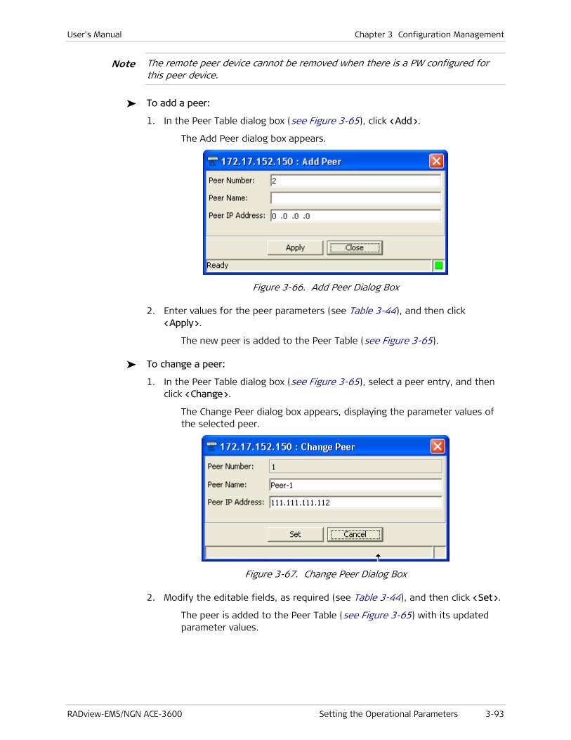
User's Manual Chapter 3 Configuration Management
RADview-EMS/NGN ACE-3600 Setting the Operational Parameters 3-93
The remote peer device cannot be removed when there is a PW configured for this peer device.
To add a peer:
1. In the Peer Table dialog box (see Figure 3-65), click <Add>.
The Add Peer dialog box appears.
Figure 3-66. Add Peer Dialog Box
2. Enter values for the peer parameters (see Table 3-44), and then click <Apply>.
The new peer is added to the Peer Table (see Figure 3-65).
To change a peer:
1. In the Peer Table dialog box (see Figure 3-65), select a peer entry, and then click <Change>.
The Change Peer dialog box appears, displaying the parameter values of the selected peer.
Figure 3-67. Change Peer Dialog Box
2. Modify the editable fields, as required (see Table 3-44), and then click <Set>.
The peer is added to the Peer Table (see Figure 3-65) with its updated parameter values.
Note
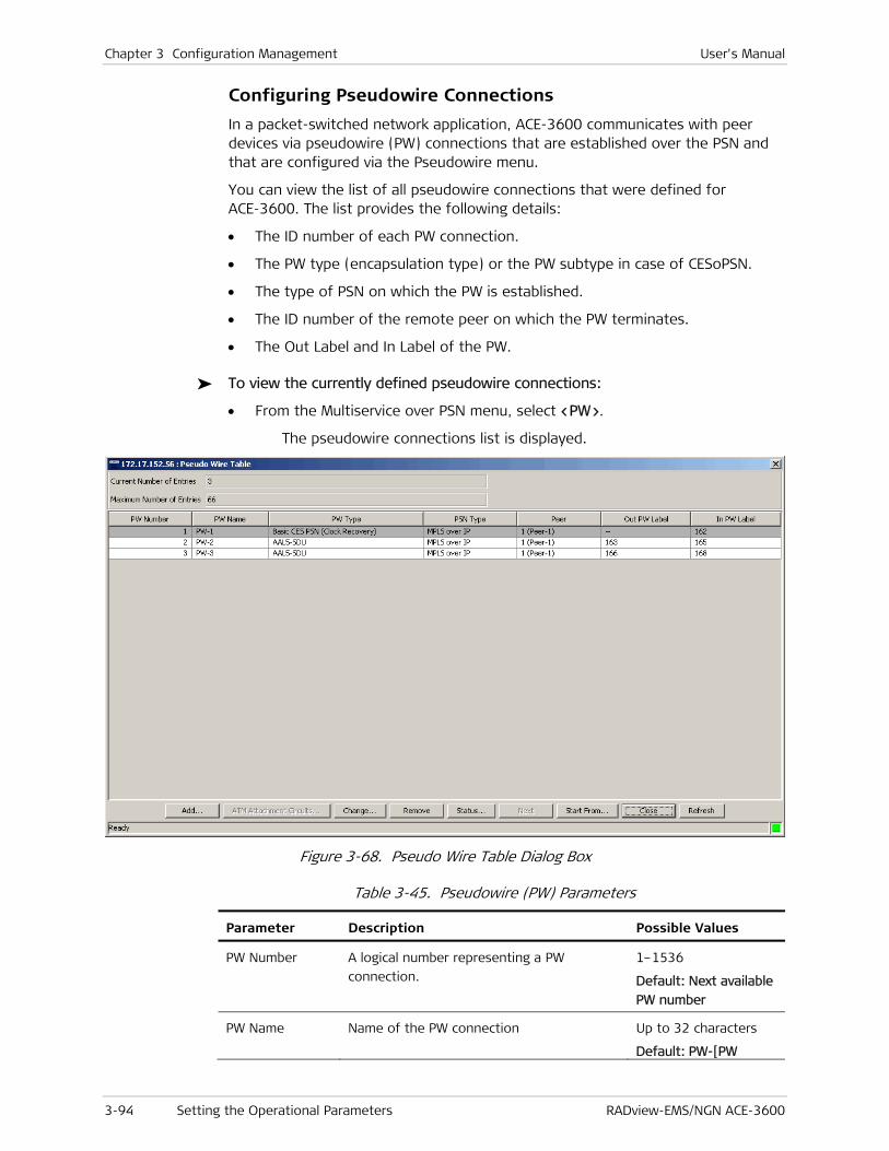
Chapter 3 Configuration Management User's Manual
3-94 Setting the Operational Parameters RADview-EMS/NGN ACE-3600
Configuring Pseudowire Connections
In a packet-switched network application, ACE-3600 communicates with peer devices via pseudowire (PW) connections that are established over the PSN and that are configured via the Pseudowire menu.
You can view the list of all pseudowire connections that were defined for ACE-3600. The list provides the following details:
• The ID number of each PW connection.
• The PW type (encapsulation type) or the PW subtype in case of CESoPSN.
• The type of PSN on which the PW is established.
• The ID number of the remote peer on which the PW terminates.
• The Out Label and In Label of the PW.
To view the currently defined pseudowire connections:
• From the Multiservice over PSN menu, select <PW>.
The pseudowire connections list is displayed.
Figure 3-68. Pseudo Wire Table Dialog Box
Table 3-45. Pseudowire (PW) Parameters
Parameter Description Possible Values
PW Number A logical number representing a PW
connection.
1–1536
Default: Next available
PW number
PW Name Name of the PW connection Up to 32 characters
Default: PW-[PW
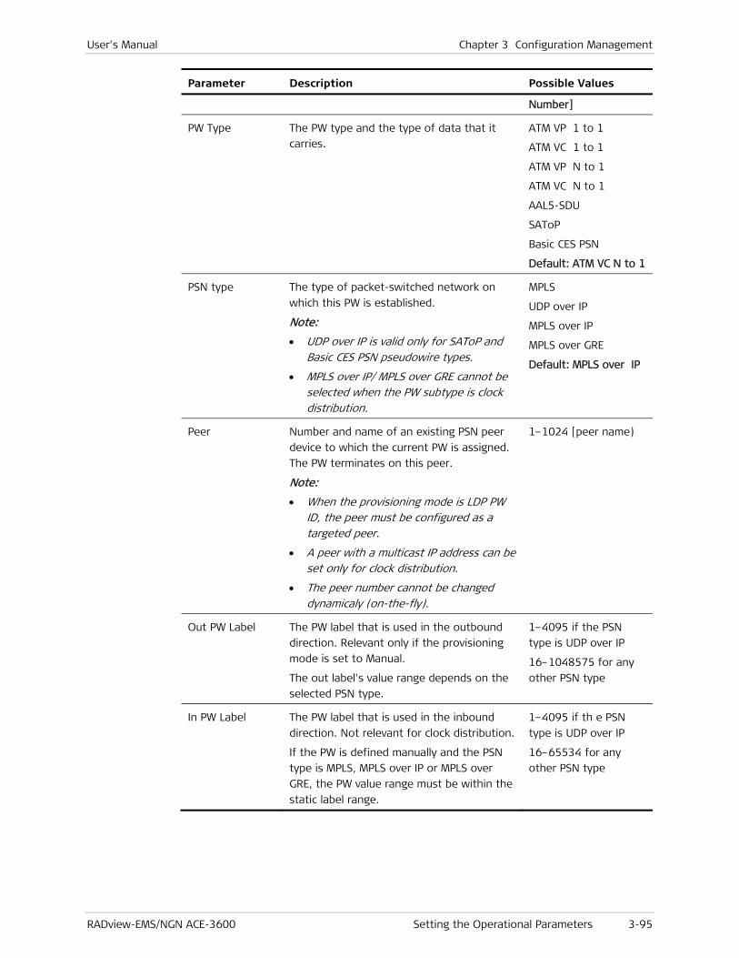
User's Manual Chapter 3 Configuration Management
RADview-EMS/NGN ACE-3600 Setting the Operational Parameters 3-95
Parameter Description Possible Values
Number]
PW Type
The PW type and the type of data that it
carries.
ATM VP 1 to 1
ATM VC 1 to 1
ATM VP N to 1
ATM VC N to 1
AAL5-SDU
SAToP
Basic CES PSN
Default: ATM VC N to 1
PSN type The type of packet-switched network on
which this PW is established.
Note:
• UDP over IP is valid only for SAToP and Basic CES PSN pseudowire types.
• MPLS over IP/ MPLS over GRE cannot be selected when the PW subtype is clock distribution.
MPLS
UDP over IP
MPLS over IP
MPLS over GRE
Default: MPLS over IP
Peer Number and name of an existing PSN peer
device to which the current PW is assigned.
The PW terminates on this peer.
Note:
• When the provisioning mode is LDP PW ID, the peer must be configured as a targeted peer.
• A peer with a multicast IP address can be set only for clock distribution.
• The peer number cannot be changed dynamicaly (on-the-fly).
1–1024 [peer name)
Out PW Label The PW label that is used in the outbound
direction. Relevant only if the provisioning
mode is set to Manual.
The out label's value range depends on the
selected PSN type.
1–4095 if the PSN
type is UDP over IP
16–1048575 for any
other PSN type
In PW Label The PW label that is used in the inbound
direction. Not relevant for clock distribution.
If the PW is defined manually and the PSN
type is MPLS, MPLS over IP or MPLS over
GRE, the PW value range must be within the
static label range.
1–4095 if th e PSN
type is UDP over IP
16–65534 for any
other PSN type

Chapter 3 Configuration Management User's Manual
3-96 Setting the Operational Parameters RADview-EMS/NGN ACE-3600
Creating a New PW
You can create and configure a new Pseudowire by following the steps in the following four stages:
• Creating a PW
• Configuring the General Parameters for the PW Connection
• Configuring the PSN Parameters for the PW Connection
• Configuring the ATM Service Parameters for the PW.
Creating a PW
To create a PW:
• In the Pseudowire Table dialog box (see Figure 3-68), click <Add>.
The Add Pseudowire – General Parameters dialog box appears (see Figure 3-69).
Configuring the General Parameters for the PW Connection
Each pseudowire connection has general parameters that must be defined separately.

User's Manual Chapter 3 Configuration Management
RADview-EMS/NGN ACE-3600 Setting the Operational Parameters 3-97
Figure 3-69. Add Pseudowire General Parameters Dialog Box
Table 3-46. Pseudowire General Parameters
Parameter Description Possible Values
PW Number The PW number of the new PW. 1 – 1536
Default: The next
available PW number.
PW Name A name for the PW connection. Up to 32 characters
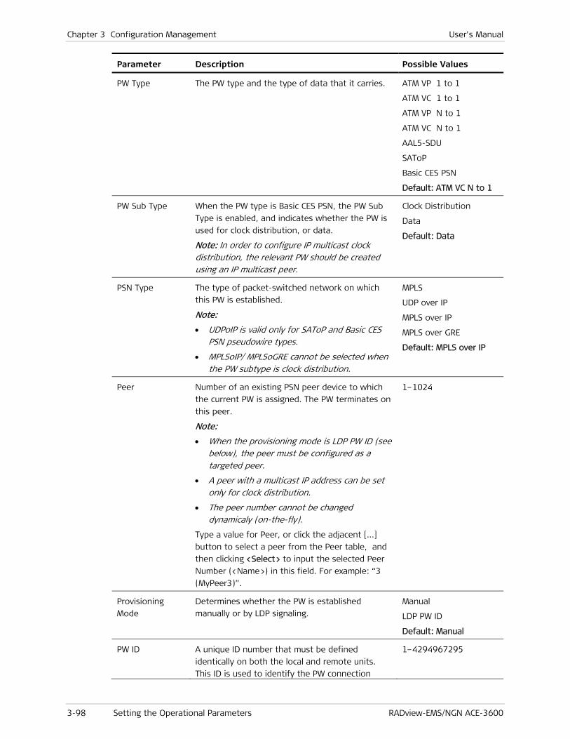
Chapter 3 Configuration Management User's Manual
3-98 Setting the Operational Parameters RADview-EMS/NGN ACE-3600
Parameter Description Possible Values
PW Type
The PW type and the type of data that it carries.
ATM VP 1 to 1
ATM VC 1 to 1
ATM VP N to 1
ATM VC N to 1
AAL5-SDU
SAToP
Basic CES PSN
Default: ATM VC N to 1
PW Sub Type When the PW type is Basic CES PSN, the PW Sub
Type is enabled, and indicates whether the PW is
used for clock distribution, or data.
Note: In order to configure IP multicast clock distribution, the relevant PW should be created using an IP multicast peer.
Clock Distribution
Data
Default: Data
PSN Type The type of packet-switched network on which
this PW is established.
Note:
• UDPoIP is valid only for SAToP and Basic CES PSN pseudowire types.
• MPLSoIP/ MPLSoGRE cannot be selected when the PW subtype is clock distribution.
MPLS
UDP over IP
MPLS over IP
MPLS over GRE
Default: MPLS over IP
Peer Number of an existing PSN peer device to which
the current PW is assigned. The PW terminates on
this peer.
Note:
• When the provisioning mode is LDP PW ID (see below), the peer must be configured as a targeted peer.
• A peer with a multicast IP address can be set only for clock distribution.
• The peer number cannot be changed dynamicaly (on-the-fly).
Type a value for Peer, or click the adjacent […]
button to select a peer from the Peer table, and
then clicking <Select> to input the selected Peer
Number (<Name>) in this field. For example: “3
(MyPeer3)”.
1–1024
Provisioning
Mode
Determines whether the PW is established
manually or by LDP signaling.
Manual
LDP PW ID
Default: Manual
PW ID A unique ID number that must be defined
identically on both the local and remote units.
This ID is used to identify the PW connection
1–4294967295
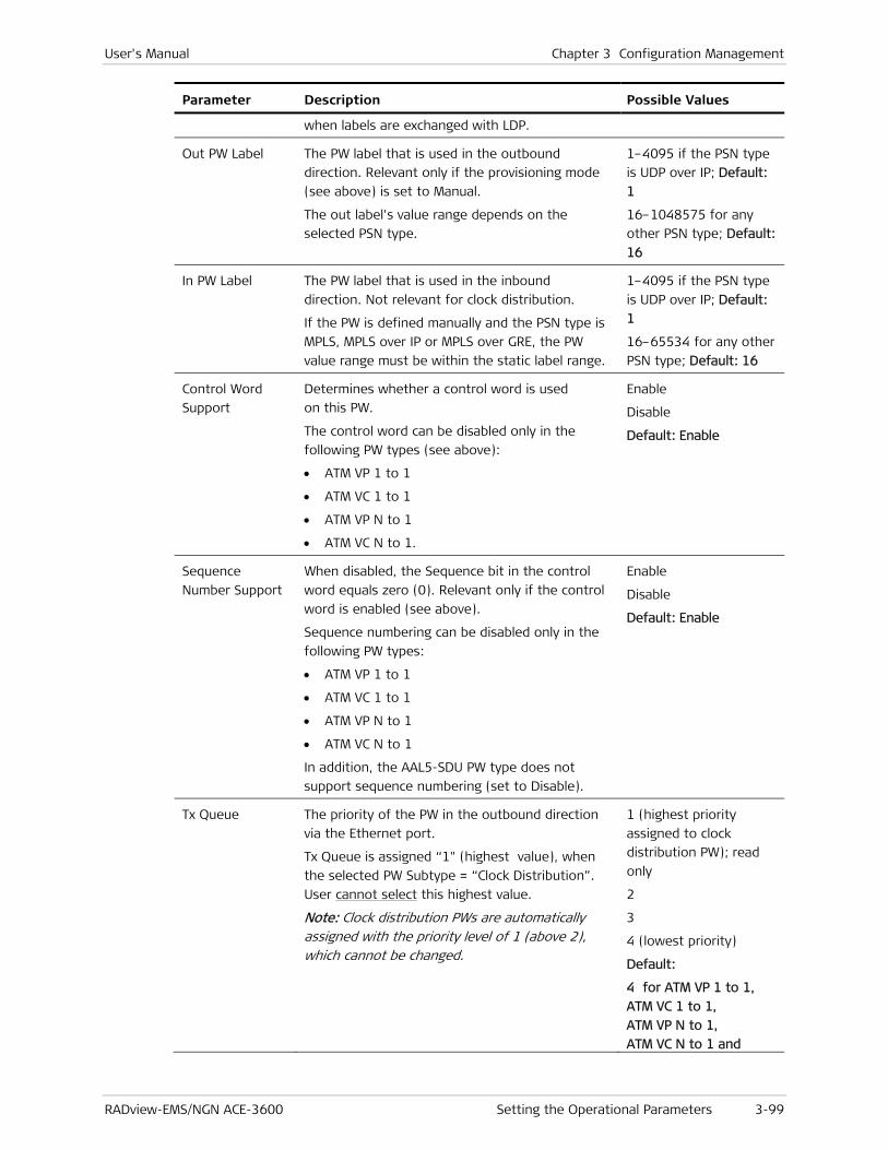
User's Manual Chapter 3 Configuration Management
RADview-EMS/NGN ACE-3600 Setting the Operational Parameters 3-99
Parameter Description Possible Values
when labels are exchanged with LDP.
Out PW Label The PW label that is used in the outbound
direction. Relevant only if the provisioning mode
(see above) is set to Manual.
The out label's value range depends on the
selected PSN type.
1–4095 if the PSN type
is UDP over IP; Default:
1
16–1048575 for any
other PSN type; Default:
16
In PW Label The PW label that is used in the inbound
direction. Not relevant for clock distribution.
If the PW is defined manually and the PSN type is
MPLS, MPLS over IP or MPLS over GRE, the PW
value range must be within the static label range.
1–4095 if the PSN type
is UDP over IP; Default:
1
16–65534 for any other
PSN type; Default: 16
Control Word
Support
Determines whether a control word is used
on this PW.
The control word can be disabled only in the
following PW types (see above):
• ATM VP 1 to 1
• ATM VC 1 to 1
• ATM VP N to 1
• ATM VC N to 1.
Enable
Disable
Default: Enable
Sequence
Number Support
When disabled, the Sequence bit in the control
word equals zero (0). Relevant only if the control
word is enabled (see above).
Sequence numbering can be disabled only in the
following PW types:
• ATM VP 1 to 1
• ATM VC 1 to 1
• ATM VP N to 1
• ATM VC N to 1
In addition, the AAL5-SDU PW type does not
support sequence numbering (set to Disable).
Enable
Disable
Default: Enable
Tx Queue The priority of the PW in the outbound direction
via the Ethernet port.
Tx Queue is assigned “1" (highest value), when
the selected PW Subtype = “Clock Distribution”.
User cannot select this highest value.
Note: Clock distribution PWs are automatically assigned with the priority level of 1 (above 2), which cannot be changed.
1 (highest priority
assigned to clock
distribution PW); read
only
2
3
4 (lowest priority)
Default:
4 for ATM VP 1 to 1,
ATM VC 1 to 1,
ATM VP N to 1,
ATM VC N to 1 and

Chapter 3 Configuration Management User's Manual
3-100 Setting the Operational Parameters RADview-EMS/NGN ACE-3600
Parameter Description Possible Values
AAL5-SDU
2 for SAT over P and
Basic CES PSN
OAM mode Determines whether the OAM feature (using
VCCV-BFD messages) is enabled for this PW.
Not relevant if the PW type is SAToP, Basic
CES PSN, or AAL5-SDU. Field has the value led
with “Disable” when selected Control Word
Support = “Disable
Disable
VCCV-BFD
Default: Disabled
Min Tx interval
(μsec)
The minimum time interval in microseconds that
the system uses between transmitted BFD control
packets. Relevant only if the OAM mode
(see above) is set to VCCV-BFD.
1000000–4294967295
Default: 100000
Mix Rx interval
(μsec)
The minimum time interval in microseconds that
the system uses between received BFD control
packets. Relevant only if the OAM mode
(see above) is set to VCCV-BFD.
1000000–4294967295
Default: 100000
Detection
Multiplier
The negotiated transmit interval, multiplied by
this value, provides the detection time for the
transmitting system. Relevant only if the OAM
mode (see above) is set to VCCV-BFD.
2–60
Default: 5
The general PW parameters cannot be changed dynamically (on-the-fly).
To configure the PW general parameters:
• In the Add General Parameters dialog box (see Figure 3-69), enter values for the parameters, as required (see Table 3-46), and then click <Next>.
The Add Pseudowire - PSN Parameters dialog box is displayed (see Figure 3-70).
Configuring the PSN Parameters for the PW Connection
Each configured PW connection requires specific definitions for the selected packet-switched network on which it is configured.
Note

User's Manual Chapter 3 Configuration Management
RADview-EMS/NGN ACE-3600 Setting the Operational Parameters 3-101
Figure 3-70. Add Pseudowire PSN Parameters Dialog Box
Table 3-47. Pseudowire PSN Parameters
Parameter Description Possible Values
PW Number Displays the PW number that you defined in the
PW general parameters (read-only).
See Table 3-46
PW Name Displays the PW name that you defined in the PW
general parameters (read-only).
See Table 3-46
PW Type Displays the PW type that you defined in the PW
general parameters (read only).
See Table 3-46
PW Sub Type Displays the PW subtype that you defined in the
PW general parameters, only if it was defined as
enabled.
See Table 3-46

Chapter 3 Configuration Management User's Manual
3-102 Setting the Operational Parameters RADview-EMS/NGN ACE-3600
Parameter Description Possible Values
PSN Type Displays the PSN type that you defined in the PW
general parameters (read only).
See Table 3-46
TOS Value of the TOS byte that is used on outbound
traffic. Relevant only when the PSN type is UDP
over IP, MPLS over IP, or MPLS over GRE.
0–255
Default: 0
Ingress Tunnel
Checkbox + RO-
box
Relevant only for MPLS-based PSNs, and not
displayed for clock distribution.
When the checkbox is selected, the /…/ button
adjacent to the Ingress Tunnel parameter
becomes enabled.
Select an ingress tunnel as follows:
1. Click the /…/ button to open the Ingress LSP
Tunnel dialog box.
2. Select an LSP tunnel, and then click <Select>.
The RO-box is filled with Index (<Name>). For
example, “4 (MyInTunnel4)”.
Note:
• The ingress tunnel's traffic descriptor must be configured in advance.
• The ingress tunnel provisioning mode (manual or LDP-driven) must be the same as the egress tunnel provisioning mode.
Cleared
Selected
Default: Cleared
Egress Tunnel
Checkbox + RO-
box
Relevant only for MPLS-based PSNs and only if
the PW subtype is data or clock distribution.
When the checkbox is selected, the /…/ button
adjacent to the Egress Tunnel parameter becomes
enabled.
Select an egress tunnel as follows:
1. Click the /…/ button to open the Egress LSP
Tunnel dialog box.
2. Select an LSP tunnel, and then click <Select>.
The RO-box is filled with Index (<Name>). For
example, “4 (MyInTunnel4)”.
Note:
• The egress tunnel's traffic descriptor must be configured in advance.
• The egress tunnel provisioning mode (manual or LDP-driven) must be the same as the ingress tunnel provisioning mode.
• If the provisioning mode is LDP-driven, the peer number of the Egress Tunnel menu must be the same as the peer number in the PW General Parameters menu.
Cleared
Selected
Default: Cleared
EXP Bits The required value for the EXP bits to be used on 0–7
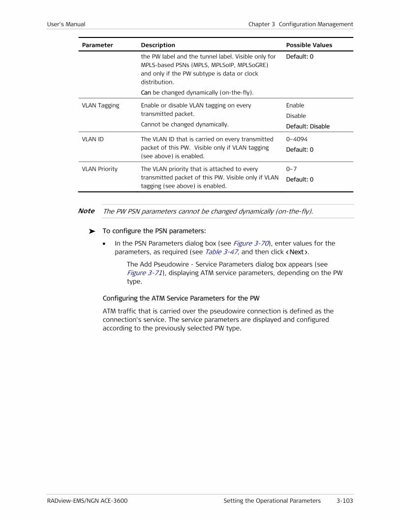
User's Manual Chapter 3 Configuration Management
RADview-EMS/NGN ACE-3600 Setting the Operational Parameters 3-103
Parameter Description Possible Values
the PW label and the tunnel label. Visible only for
MPLS-based PSNs (MPLS, MPLSoIP, MPLSoGRE)
and only if the PW subtype is data or clock
distribution.
Can be changed dynamically (on-the-fly).
Default: 0
VLAN Tagging Enable or disable VLAN tagging on every
transmitted packet.
Cannot be changed dynamically.
Enable
Disable
Default: Disable
VLAN ID The VLAN ID that is carried on every transmitted
packet of this PW. Visible only if VLAN tagging
(see above) is enabled.
0–4094
Default: 0
VLAN Priority The VLAN priority that is attached to every
transmitted packet of this PW. Visible only if VLAN
tagging (see above) is enabled.
0–7
Default: 0
The PW PSN parameters cannot be changed dynamically (on-the-fly).
To configure the PSN parameters:
• In the PSN Parameters dialog box (see Figure 3-70), enter values for the parameters, as required (see Table 3-47, and then click <Next>.
The Add Pseudowire - Service Parameters dialog box appears (see Figure 3-71), displaying ATM service parameters, depending on the PW type.
Configuring the ATM Service Parameters for the PW
ATM traffic that is carried over the pseudowire connection is defined as the connection's service. The service parameters are displayed and configured according to the previously selected PW type.
Note
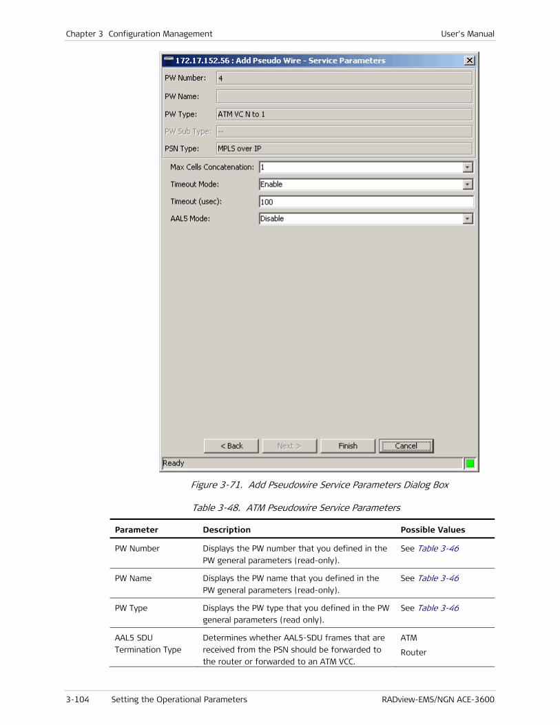
Chapter 3 Configuration Management User's Manual
3-104 Setting the Operational Parameters RADview-EMS/NGN ACE-3600
Figure 3-71. Add Pseudowire Service Parameters Dialog Box
Table 3-48. ATM Pseudowire Service Parameters
Parameter Description Possible Values
PW Number Displays the PW number that you defined in the
PW general parameters (read-only).
See Table 3-46
PW Name Displays the PW name that you defined in the
PW general parameters (read-only).
See Table 3-46
PW Type Displays the PW type that you defined in the PW
general parameters (read only).
See Table 3-46
AAL5 SDU
Termination Type
Determines whether AAL5-SDU frames that are
received from the PSN should be forwarded to
the router or forwarded to an ATM VCC.
ATM
Router
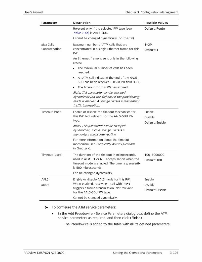
User's Manual Chapter 3 Configuration Management
RADview-EMS/NGN ACE-3600 Setting the Operational Parameters 3-105
Parameter Description Possible Values
Relevant only if the selected PW type (see
Table 3-46) is AAL5-SDU.
Cannot be changed dynamically (on-the-fly).
Default: Router
Max Cells
Concatenation
Maximum number of ATM cells that are
concentrated in a single Ethernet frame for this
PW.
An Ethernet frame is sent only in the following
cases:
• The maximum number of cells has been
reached.
• An ATM cell indicating the end of the AAL5-
SDU has been received (LBS in PTI field is 1).
• The timeout for this PW has expired.
Note: This parameter can be changed dynamically (on-the-fly) only if the provisioning mode is manual. A change causes a momentary traffic interruption.
1–29
Default: 1
Timeout Mode Enable or disable the timeout mechanism for
this PW. Not relevant for the AAL5-SDU PW
type.
Note: This parameter can be changed dynamically; such a change causes a momentary traffic interruption.
For more information about the timeout
mechanism, see Frequently Asked Questions
in Chapter 6.
Enable
Disable
Default: Enable
Timeout (μsec)
The duration of the timeout in microseconds,
used in ATM 1:1 or N:1 encapsulation when the
timeout mode is enabled. The timer's granularity
is 500 microseconds.
Can be changed dynamically.
100–5000000
Default: 100
AAL5
Mode
Enable or disable AAL5 mode for this PW.
When enabled, receiving a cell with PTI=1
triggers a frame transmission. Not relevant
for the AAL5-SDU PW type.
Cannot be changed dynamically.
Enable
Disable
Default: Disable
To configure the ATM service parameters:
• In the Add Pseudowire - Service Parameters dialog box, define the ATM service parameters as required, and then click <Finish>.
The Pseudowire is added to the table with all its defined parameters.

Chapter 3 Configuration Management User's Manual
3-106 Setting the Operational Parameters RADview-EMS/NGN ACE-3600
Configuring the ATM Attachment Circuit Parameters for the PW
To access the ATM attachment circuit parameters:
• From the Pseudowire Table dialog box (see Figure 3-68), click <ATM Attachment Circuits>.
The ATM Attachment Circuits Table dialog box appears, displaying attachment circuit parameters for ATM PW.
Figure 3-72. ATM Attachment Circuits Table Dialog Box
Table 3-49. Attachment Circuit Parameters for ATM PW
Parameter Description Possible Values
PW Number Displays the PW number that you defined in the
PW general parameters (read-only).
See Table 3-46
PW Name Displays the PW name that you defined in the PW
general parameters (read-only).
See Table 3-46
PW Type Displays the PW type that you defined in the PW
general parameters (read only).
See Table 3-46
PSN Type Displays the PSN type that you defined in the PW
general parameters (read only).
See Table 3-46
PW Current
Number of
Attachment
Number of attachment circuits defined in the
table.
0–32

User's Manual Chapter 3 Configuration Management
RADview-EMS/NGN ACE-3600 Setting the Operational Parameters 3-107
Parameter Description Possible Values
Circuits
PW Maximum
Number of
Attachment
Circuits
Maximum number of attachment circuits that can
be defined in the table.
32
Port Type and number of the port from which the PW
traffic originated.
ATM-155 1–8
VPI The virtual path identifier of the originating
traffic.
The VPI parameter cannot be used here if it is in
use by another VP XC, or if the VPI/VCI is in use by
another ATM PW or ATM VC.
0–4095
VCI The virtual channel identifier of the originating
traffic. Visible only if the PW type is VC 1:1 or
VC N:1.
The VPI parameter cannot be used here if it is in
use by another VP XC, or if the VPI/VCI is in use by
another VC XC.
32–65535
VPI to PSN The virtual path identifier that should be carried
toward the PSN by this N:1 PW. Visible only for
the N:1 VC and N:1 VP PW types.
This parameter is automatically filled according to
the VPI value (see above).
0–4095
VCI to PSN The virtual channel identifier that should be
carried over the PSN by this N:1 PW. Visible only
for the N:1 VC PW type.
This parameter is automatically filled according to
the VPI value (see above).
32–65535
VPI from PSN The virtual path identifier that is expected from
the PSN side on this N:1 PW. Visible only for the
N:1 VC and N:1 VP PW types.
This parameter is automatically filled according to
the VPI value (see above). You can set another
value as long as it is unique for this PW.
0–4095
VCI from PSN The virtual channel identifier that is expected
from the PSN on this N:1 PW. Visible only for the
N:1 VC PW type.
This parameter is automatically filled according to
the VPI value (see above). You can set another
value as long as it is unique for this PW.
32–65535
In Traffic
Descriptor
ID number of a previously defined policing
traffic descriptor (In direction), relevant for this
PW.
For N:1 encapsulation, the Traffic Descriptor
0–99999
Default: 0

Chapter 3 Configuration Management User's Manual
3-108 Setting the Operational Parameters RADview-EMS/NGN ACE-3600
Parameter Description Possible Values
setting is applied on all the VCs/VPCs connected
to the PW (policing is performed at the PW level).
Note:
• The traffic descriptor of all the VCs attached to the same N:1 PW must be the same.
• When the TD is set to 0, the policing for the selected ATM channel is stopped.
• Can be changed dynamically (on-the-fly) as long as it has the same service category and mode.
Out Traffic
Descriptor
ID number of a previously defined
traffic descriptor (Out direction), relevant for this
PW.
For N:1 encapsulation, the TD setting is applied
on all the VCs/VPCs connected to the PW (shaping
is performed at the PW level).
Note:
• The traffic descriptor of all the VCs attached to the same N:1 PW must be the same.
• A TD that is automatically created for a CES connection cannot be used.
• Can be changed dynamically (on-the-fly) as long as it has the same service category and mode.
1–99999
Default: 1
OAM Descriptor ID number of a previously defined OAM descriptor
that is relevant to this PW. The OAM descriptor
type must be Intermediate.
1–256
Default: 1
• All attachment circuit parameters except Traffic Descriptor cannot be changed dynamically (on-the-fly).
• The Save (S) and Remove (R) menu functions appear on this submenu to allow addition/removal of any VCC/VPC connected to the N:1 PW.
To add an ATM attachment circuit to the table:
1. In the ATM Attachment Circuit dialog box (see Figure 3-72), click <Add>.
The Add ATM Attachment Circuit dialog box is displayed.
Note
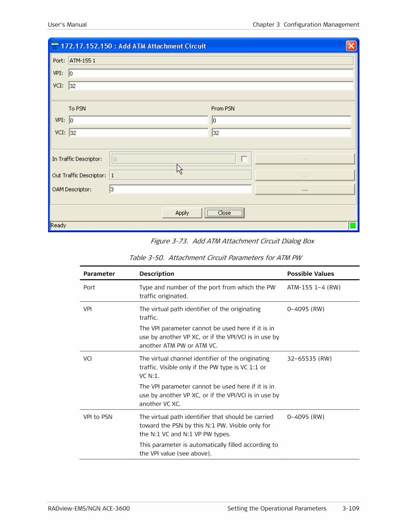
User's Manual Chapter 3 Configuration Management
RADview-EMS/NGN ACE-3600 Setting the Operational Parameters 3-109
Figure 3-73. Add ATM Attachment Circuit Dialog Box
Table 3-50. Attachment Circuit Parameters for ATM PW
Parameter Description Possible Values
Port Type and number of the port from which the PW
traffic originated.
ATM-155 1–4 (RW)
VPI The virtual path identifier of the originating
traffic.
The VPI parameter cannot be used here if it is in
use by another VP XC, or if the VPI/VCI is in use by
another ATM PW or ATM VC.
0–4095 (RW)
VCI The virtual channel identifier of the originating
traffic. Visible only if the PW type is VC 1:1 or
VC N:1.
The VPI parameter cannot be used here if it is in
use by another VP XC, or if the VPI/VCI is in use by
another VC XC.
32–65535 (RW)
VPI to PSN The virtual path identifier that should be carried
toward the PSN by this N:1 PW. Visible only for
the N:1 VC and N:1 VP PW types.
This parameter is automatically filled according to
the VPI value (see above).
0–4095 (RW)
Chapter 3 Configuration Management User's Manual
3-110 Setting the Operational Parameters RADview-EMS/NGN ACE-3600
Parameter Description Possible Values
VCI to PSN The virtual channel identifier that should be
carried over the PSN by this N:1 PW. Visible only
for the N:1 VC PW type.
This parameter is automatically filled according to
the VPI value (see above).
32–65535 (RW)
VPI from PSN The virtual path identifier that is expected from
the PSN side on this N:1 PW. Visible only for the
N:1 VC and N:1 VP PW types.
This parameter is automatically filled according to
the VPI value (see above). You can set another
value as long as it is unique for this PW.
0–4095 (RW)
VCI from PSN The virtual channel identifier that is expected
from the PSN on this N:1 PW. Visible only for the
N:1 VC PW type.
This parameter is automatically filled according to
the VPI value (see above). You can set another
value as long as it is unique for this PW.
32–65535 (RW)
In Traffic
Descriptor
Checkbox + RO
box
When the “In Traffic Descriptor” check-box is
cleared, the RO-box is disabled.
When the “In Traffic Descriptor” check-box is
selected, the RO-box is enabled, and you can
enter an ID number of a previously defined
policing traffic descriptor (In direction), relevant
for this PW, by either:
• Typing the ID number into the RO box
Or by
• Clicking the […] button to display the Traffic
Descriptor table, selecting a traffic descriptor,
and then clicking <Select> to place the
selected traffic descriptor in this field.
For N:1 encapsulation, the Traffic Descriptor
setting is applied on all the VCs/VPCs connected
to the PW (policing is performed at the PW level).
Note:
• The traffic descriptor of all the VCs attached to the same N:1 PW must be the same.
• When the TD is set to 0, the policing for the selected ATM channel is stopped.
• Can be changed dynamically (on-the-fly) as long as it has the same service category and mode.
Checkbox:
Selected, Cleared
Default: Selected
RO box:
0–99999
Default: 0
Out Traffic
Descriptor
ID number of a previously defined
traffic descriptor (Out direction), relevant for this
PW.
You can click the […] button to display the Traffic
1–99999
Default: 1

User's Manual Chapter 3 Configuration Management
RADview-EMS/NGN ACE-3600 Setting the Operational Parameters 3-111
Parameter Description Possible Values
Descriptor table, select a traffic descriptor, and
then click <Select> to place the selected traffic
descriptor in this field.
For N:1 encapsulation, the TD setting is applied
on all the VCs/VPCs connected to the PW (shaping
is performed at the PW level).
Note:
• The traffic descriptor of all the VCs attached to the same N:1 PW must be the same.
• A TD that is automatically created for a CES connection cannot be used.
• Can be changed dynamically (on-the-fly) as long as it has the same service category and mode.
OAM Descriptor ID number of a previously defined OAM descriptor
that is relevant to this PW.
You can click the […] button to display the OAM
Descriptor table, select an OAM descriptor, and
then click <Select> to place the selected OAM
descriptor in this field.
The OAM descriptor type must be Intermediate.
1–256
Default: 1
2. Enter values for the parameters, as required, and then click <Apply>.
The parameter is added to the ATM Attachment Circuit table (see Figure 3-72).
To change an ATM attachment circuit:
1. In the ATM Attachment Circuit dialog box (see Figure 3-72), select an entry, and then click <Change>.
The Change ATM Attachment Circuit dialog box is displayed.

Chapter 3 Configuration Management User's Manual
3-112 Setting the Operational Parameters RADview-EMS/NGN ACE-3600
Figure 3-74. Change ATM Attachment Circuit Dialog Box
2. Change the ATM attachment circuit parameters as required (see Table 3-50), and then click <Set>.
The ATM attachment circuit is updated with these new values (see Figure 3-72).
To remove an ATM attachment circuit from the table:
1. In the ATM Attachment Circuit dialog box (see Figure 3-72), select an entry, and then click <Remove>.
A confirmation box displays "Removing Attachment Circuit".
2. Click <OK> to confirm removal.
The selected attachment circuit is removed from the table.
Changing Pseudowire Parameters
You can change the general, PSN, and/or service parameters of any PW.
To change Pseudowire parameters:
1. To change pseudowire general parameters, in the Pseudowire Table (see Figure 3-68), select an entry, and then click <Change>.
The Change Pseudowire – General Parameters dialog box is displayed.

User's Manual Chapter 3 Configuration Management
RADview-EMS/NGN ACE-3600 Setting the Operational Parameters 3-113
Figure 3-75. Change Pseudowire General Parameters Dialog Box
2. Change the general parameters, as required (see Table 3-46), and then click <Next>.
The general parameters are changed, and the Change Pseudowire - PSN Parameters dialog box appears.

Chapter 3 Configuration Management User's Manual
3-114 Setting the Operational Parameters RADview-EMS/NGN ACE-3600
Figure 3-76. Change Pseudowire PSN Parameters
3. Change the PSN parameters, as required (see Table 3-47), and then click <Next>.
The PSN parameters are changed, and the Change Pseudowire - Service Parameters dialog appears.
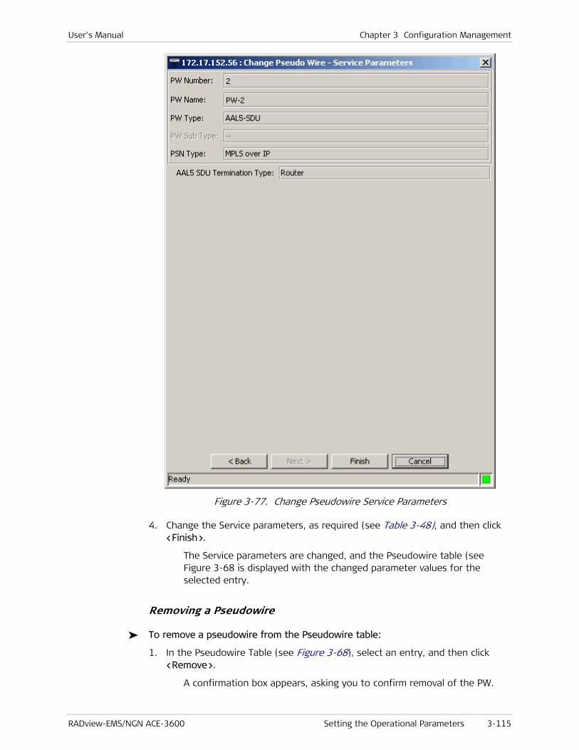
User's Manual Chapter 3 Configuration Management
RADview-EMS/NGN ACE-3600 Setting the Operational Parameters 3-115
Figure 3-77. Change Pseudowire Service Parameters
4. Change the Service parameters, as required (see Table 3-48), and then click <Finish>.
The Service parameters are changed, and the Pseudowire table (see Figure 3-68 is displayed with the changed parameter values for the selected entry.
Removing a Pseudowire
To remove a pseudowire from the Pseudowire table:
1. In the Pseudowire Table (see Figure 3-68), select an entry, and then click <Remove>.
A confirmation box appears, asking you to confirm removal of the PW.
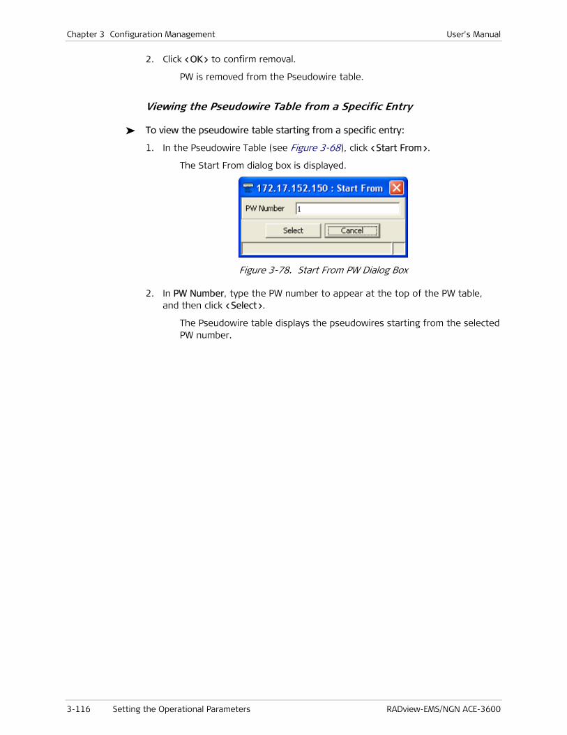
Chapter 3 Configuration Management User's Manual
3-116 Setting the Operational Parameters RADview-EMS/NGN ACE-3600
2. Click <OK> to confirm removal.
PW is removed from the Pseudowire table.
Viewing the Pseudowire Table from a Specific Entry
To view the pseudowire table starting from a specific entry:
1. In the Pseudowire Table (see Figure 3-68), click <Start From>.
The Start From dialog box is displayed.
Figure 3-78. Start From PW Dialog Box
2. In PW Number, type the PW number to appear at the top of the PW table, and then click <Select>.
The Pseudowire table displays the pseudowires starting from the selected PW number.

User's Manual Chapter 3 Configuration Management
RADview-EMS/NGN ACE-3600 Additional Tasks 3-117
3.3 Additional Tasks
You can perform additional tasks from time to time, as required or if helpful, as described in this section:
• Polling the Hardware
• Resetting the Hardware
• Restoring the Default System Configuration
• Viewing and Swapping Software Files
• Saving/Deleting the Default Configuration File
• Downloading Software via a TFTP Server
• Downloading a Preset Configuration via a TFTP Server.
Polling the Hardware
You can instruct ACE-3600 to immediately poll data from the Agent and update the polling information as necessary.
To poll the agent:
• From the Configuration menu, select System Commands>Poll Agent.
The system immediately polls the agent and updates the displayed information.
Table 3-51. Polled MIB Objects
No. Parameter/MIB Object Description
1 3418.sysObjectID Detects whether the device has been
changed between polling sessions.
2 rad.atmNteCardType Displays the modules.
3 rad.atmNteProgCardType Detects the module status together with
rad.atmNteCardType.
4 Rad.modlParamLeds Displays the module LEDs, their colors, and
their status.
5 2863.ifOperStatus and
2863.ifAdminStatus of each
existing physical interface
Displays the existing ports and their status.
6 Rad.prtParamAlarmIndication (of
each existing physical interface)
Displays existing ports and their status
(aggregation of all ports’ levels).
7 Rad.physicalConnector Displays the correct connector of existing
ports.
9 rad.systemPsType Displays the correct type of power
supply(s).
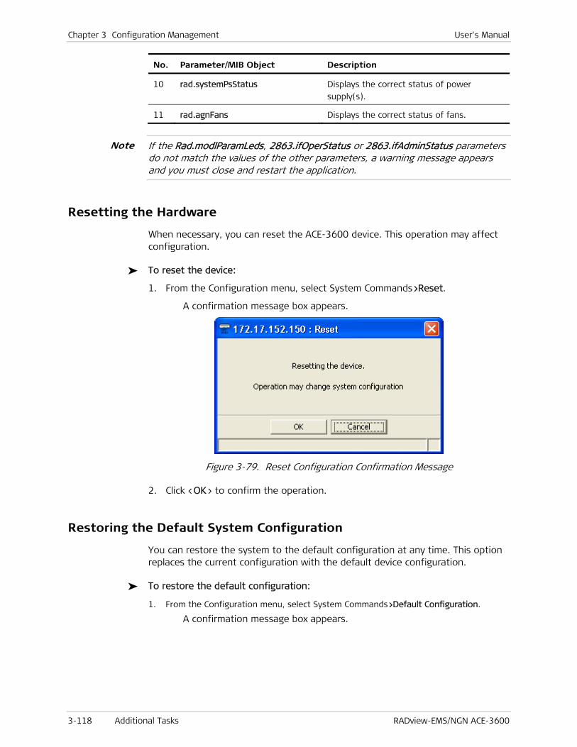
Chapter 3 Configuration Management User's Manual
3-118 Additional Tasks RADview-EMS/NGN ACE-3600
No. Parameter/MIB Object Description
10 rad.systemPsStatus Displays the correct status of power
supply(s).
11 rad.agnFans Displays the correct status of fans.
If the Rad.modlParamLeds, 2863.ifOperStatus or 2863.ifAdminStatus parameters do not match the values of the other parameters, a warning message appears and you must close and restart the application.
Resetting the Hardware
When necessary, you can reset the ACE-3600 device. This operation may affect configuration.
To reset the device:
1. From the Configuration menu, select System Commands>Reset.
A confirmation message box appears.
Figure 3-79. Reset Configuration Confirmation Message
2. Click <OK> to confirm the operation.
Restoring the Default System Configuration
You can restore the system to the default configuration at any time. This option replaces the current configuration with the default device configuration.
To restore the default configuration:
1. From the Configuration menu, select System Commands>Default Configuration.
A confirmation message box appears.
Note
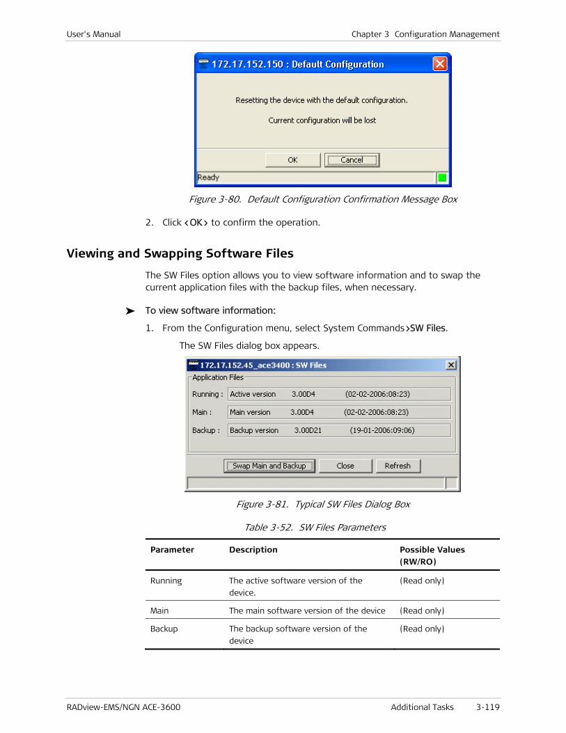
User's Manual Chapter 3 Configuration Management
RADview-EMS/NGN ACE-3600 Additional Tasks 3-119
Figure 3-80. Default Configuration Confirmation Message Box
2. Click <OK> to confirm the operation.
Viewing and Swapping Software Files
The SW Files option allows you to view software information and to swap the current application files with the backup files, when necessary.
To view software information:
1. From the Configuration menu, select System Commands>SW Files.
The SW Files dialog box appears.
Figure 3-81. Typical SW Files Dialog Box
Table 3-52. SW Files Parameters
Parameter Description Possible Values (RW/RO)
Running The active software version of the
device.
(Read only)
Main The main software version of the device (Read only)
Backup The backup software version of the
device
(Read only)

Chapter 3 Configuration Management User's Manual
3-120 Additional Tasks RADview-EMS/NGN ACE-3600
To swap between the main and backup software files:
1. In the SW Files dialog box (see Figure 3-81), click <Swap Main and Backup>.
A confirmation dialog box appears.
Figure 3-82. Swapping Confirmation Dialog Box
2. Click the type of swap you require (see Table 3-53).
Table 3-53. Swapping Confirmation Buttons
Button Description
<Swap Only> Swaps the main and backup software files of
the device.
<Swap and
Reset>
Swaps the main and backup software files of
the device and activates the new software.
<Cancel> Closes the swapping confirmation dialog box
without making any changes.
To refresh the SW Files parameter values:
• Click <Refresh>.
The most current software file information is retrieved and displayed.
To close the SW Files dialog box:
• Click <Close>.
The SW Files dialog box closes.
Saving/Deleting the Default Configuration File
The current configuration of ACE-3600, including the entire set of parameters defined through the management menus, can be saved as the default configuration, meaning that any configuration reset operation returns the unit to that saved default configuration. If there is no configuration saved as default, the factory-default settings are used on the reset operation.
To save the current configuration as default:
1. From the Configuration menu, select System Commands>Save Active Configuration of Default File.
The Save Active Configuration dialog box appears.

User's Manual Chapter 3 Configuration Management
RADview-EMS/NGN ACE-3600 Additional Tasks 3-121
Figure 3-83. Save Active Configuration Dialog Box
2. Click <OK>.
The current device configuration is saved internally as the default configuration using the *.cfg file extension.
To delete the default configuration file:
• In the Save Active Configuration dialog box (see Figure 3-83), click <OK>.
The default configuration file is deleted and the factory-default configuration is used instead.
Downloading Software via a TFTP Server
Unlike a standalone unit that does not have two main processor modules, ACE-3600 requires a special procedure for updating the software files of its two main modules that work in redundancy mode.
The software can be downloaded to the ACE-3600 main modules using one of the following procedures:
• Single traffic switch – The active main module is reset only once and traffic is affected only once.
• Double traffic switch – The active main module is reset twice and the traffic is affected twice.
To perform a single traffic switch procedure:
1. From the Start menu, select Programs>Network Managers>General>TFTP File Transfer.
The TFTP File Transfer dialog box is displayed.

Chapter 3 Configuration Management User's Manual
3-122 Additional Tasks RADview-EMS/NGN ACE-3600
Figure 3-84. TFTP File Transfer Dialog Box
2. Click <All Nodes Operation>.
The All Nodes Operation dialog box is displayed, with the default operation.
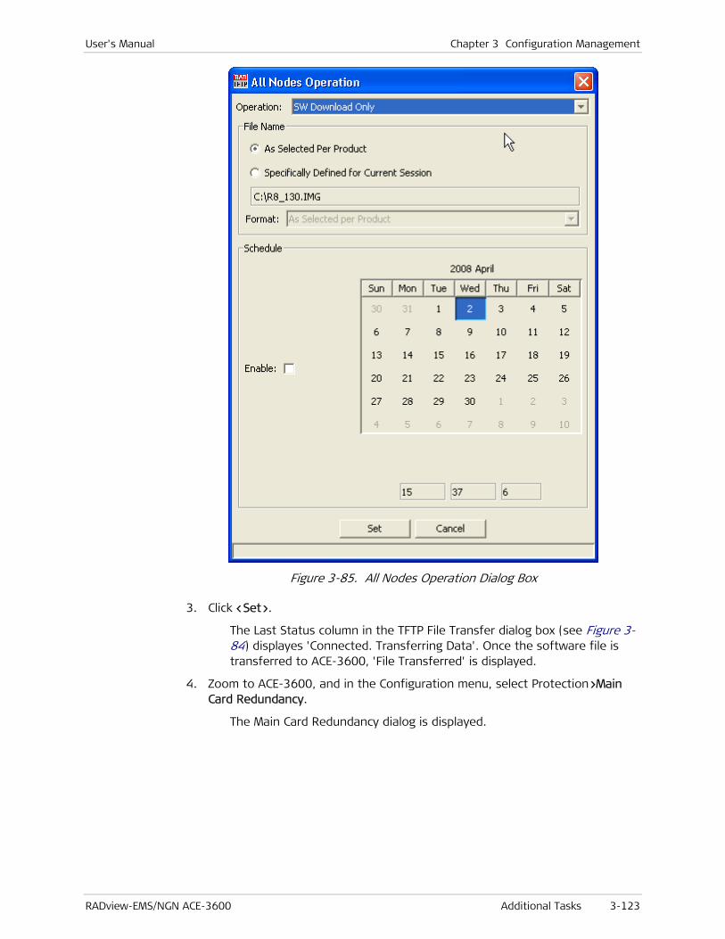
User's Manual Chapter 3 Configuration Management
RADview-EMS/NGN ACE-3600 Additional Tasks 3-123
Figure 3-85. All Nodes Operation Dialog Box
3. Click <Set>.
The Last Status column in the TFTP File Transfer dialog box (see Figure 3-84) displayes 'Connected. Transferring Data'. Once the software file is transferred to ACE-3600, 'File Transferred' is displayed.
4. Zoom to ACE-3600, and in the Configuration menu, select Protection>Main Card Redundancy.
The Main Card Redundancy dialog is displayed.

Chapter 3 Configuration Management User's Manual
3-124 Additional Tasks RADview-EMS/NGN ACE-3600
Figure 3-86. Main Card Redundancy Dialog Box
5. Click <Commands> to display a list of commands, and select the command Software Update to Card B, to update the downloaded files on Main Card B.
Figure 3-87. Main Card Redundancy Commands
6. Click <Set>.
The Software is updated to Card B.
During the software update procedure, the “Software Update operation is in progress” message is displayed at the bottom of the Main Card Redundancy window.

User's Manual Chapter 3 Configuration Management
RADview-EMS/NGN ACE-3600 Additional Tasks 3-125
When the update procedure completes, the “Ready” message is displayed at the bottom of the window.
If the redundancy status does not allow updating the downloaded files on Main Card B, an error message: "Redundancy Status does not allow performing…" is displayed in red on the status line.
7. From the Configuration menu, select Protection> Main Card Redundancy (see Figure 3-86), and then select the Reset Card B command (see Figure 3-87) to perform a reset to Main Card B.
A message box appears asking you to confirm the reset.
8. Click <OK>.
Card B is reset, and during the reset:
Redundancy Status shows a "Communication loss".
Main Card B starts with the updated software version.
Redundancy Status shows "Software Mismatch".
9. From the Configuration menu, select System Commands> Reset, to reset the active main module (Main Card A).
The Reset confirmation box is displayed.
Figure 3-88. Reset Confirmation Dialog Box
10. Click <OK>.
The device is reset:
Main Card B becomes the active main module, causing the traffic to switch to it.
Redundancy Status shows "Communication loss".
Main Card A is updated with the new software version.
Redundancy Status shows "OK" indication when the process finishes.
You can switch back to Main Card A manually, using 'Switch to other card'. However, this would affect the traffic again.
Note
Note

Chapter 3 Configuration Management User's Manual
3-126 Additional Tasks RADview-EMS/NGN ACE-3600
To perform a double traffic switch procedure:
1. From the Start menu, select Programs>Network Managers>General>TFTP File Transfer.
The TFTP File Transfer dialog box is displayed (see Figure 3-84).
2. Click <All Nodes Operation>.
The All Nodes Operation dialog box is displayed (see Figure 3-85).
3. In Operation, click the down arrow.
The Operation options are displayed in the drop-down list.
Figure 3-89. Operation Options
4. In Operation, select SW Download & Reboot, to initiate the Software Download & Reboot command.
5. Click <Set>.
The Last Status column in the TFTP File Transfer dialog box (see Figure 3-84) displays 'Connected. Transferring Data'. Once the software file is transferred to ACE-3600, 'File Transferred' is displayed and the unit performs an automatic restart (reboot).
During the restart:
Main Card B becomes the active main module, causing the traffic to switch to it.
Redundancy Status shows "Communication loss".
Main Card A is updated with the new software version.
Redundancy Status shows "Software Mismatch".
6. Repeat the Software Download & Reboot procedure for Main Card B, which is the active main module.
The same restart process is performed on Main Card B. Main Card A becomes the active main module, causing the traffic to switch back to it.
Downloading a Preset Configuration via a TFTP Server
The timesaving alternative to the manual window-by-window configuration is loading a full preset configuration file to the unit, provided that such configuration is available.

User's Manual Chapter 3 Configuration Management
RADview-EMS/NGN ACE-3600 Additional Tasks 3-127
To load a preset configuration to ACE-3600:
1. From the Start menu, select Programs>Network Managers>General>TFTP File Transfer.
The TFTP File Transfer dialog box is displayed (see Figure 3-84).
2. Click <All Nodes Operation>.
The All Nodes Operation dialog box is displayed (see Figure 3-85).
3. In Operation, click the down arrow.
The Operation options are displayed in the drop-down list (see Figure 3-89).
4. In Operation, select Config. Download & Reboot, to initiate the Configuration Download & Reboot command.
5. Click <Set>.
The download is performed to the active main module (Main Card A). During the download, the Last Status column in the TFTP File Transfer dialog box (see Figure 3-84) displays 'Connected, Transferring data'. Once the software file is transferred to ACE-3600, 'File Transferred' is displayed.
Once the download is complete, the unit automatically reboots itself. During the reset (reboot):
Main Card B becomes the active main module, causing the traffic to switch to it.
Redundancy Status display 'Communication loss', and then at the end of the process displays 'Configuration mismatch'.
6. Repeat the Configuration Download & Reboot command for Main Card B, which is the currently active main module.
Once the download is complete, the unit automatically reboots itself. During the reset:
Main Card A becomes the active main module again, causing the traffic to switch back to it.
Redundancy Status displays 'Communication loss' and then at the end of the process displays 'OK'.

Chapter 3 Configuration Management User's Manual
3-128 Additional Tasks RADview-EMS/NGN ACE-3600

RADview-EMS/NGN ACE-3600 3G Services over PSN 4-1
Chapter 4
Configuring a Typical Application This chapter describes the configuration of ACE-3600 in a typical application, and provides practical configuration examples for implementing it.
The following sections describe:
• 3G Services over PSN
• Configuring the ACE-3600 Unit.
4.1 3G Services over PSN
In a typical ATM over PSN application (see Figure 4-1), 3G cellular traffic (ATM) is transmitted over the PSN by the remote peers (ACE-3100 and ACE-3200) using pseudowires that comprise uniquely formatted Ethernet packets. ACE-3600 receives the Ethernet packets via its Gigabit Ethernet interface, and converts it back to ATM-155 traffic, carried by up to four STM-1/OC-3c links towards the RNC. In such an application, ACE-3600 can serve as the clock distributor for the remote peers.
Figure 4-1. Emulated ATM Services over PSN
In the typical application illustrated in the above figure (see Figure 4-1):

Chapter 4 Configuring a Typical Application User's Manual
4-2 Configuring the ACE-3600 Unit RADview-EMS/NGN ACE-3600
• Two 3G Node B units are connected to the ACE-3100 and ACE-3200 units, which serve as the remote gateways.
• Node B (1) is connected to ACE-3100 via an STM-1/OC-3 link, and Node B (2) is connected to ACE-3200 via an E1/T1/J1 IMA link.
• On the central site side, a 3G RNC is connected to ACE-3600, which serves as the central gateway. The RNC is connected to ACE-3600 via multiple STM-1/OC-3 links, using automatic protection switching (APS; optional).
• On the ACE-3600 side, one VP connection and one VC connection are configured for each remote gateway unit that interconnects with a 3G Node B unit.
• The 3G RNC provides the timing reference to ACE-3600, and the clock/timing is then distributed by ACE-3600 over the PSN towards ACE-3100 and ACE-3200 (that are able to recover the clock).
A network management station connected to the PSN can manage all units over an IP-based format.
4.2 Configuring the ACE-3600 Unit
The ACE-3600 configuration stages are:
a. Configuring the Physical Layer Parameters – which includes:
Configuring the ATM-155 Ports
Configuring the GbE Ports
Configuring the Ethernet Port
b. Setting the Protection Parameters– which includes:
Setting System Redundancy
Setting Ethernet Redundancy
Setting ATM-155 Port Protection
c. Configuring the Application Parameters– which includes:
Configuring the Router Parameters
Configuring the Traffic Descriptors
Configuring the General Multiservice PW over PSN Parameters
Configuring the Remote Peer Parameters
Configuring the Pseudowire Parameters
d. Setting the Clock Source
e. Defining the Manager IP Address
Please see the ACE-3100, ACE-3200 Installation and Operation Manual for instructions regarding the ACE-3100 and ACE-3200 unit in this typical application.
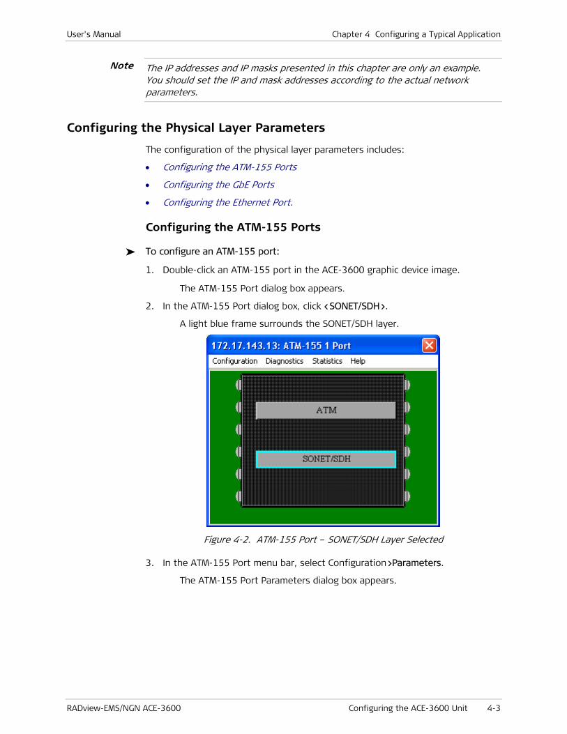
User's Manual Chapter 4 Configuring a Typical Application
RADview-EMS/NGN ACE-3600 Configuring the ACE-3600 Unit 4-3
The IP addresses and IP masks presented in this chapter are only an example. You should set the IP and mask addresses according to the actual network parameters.
Configuring the Physical Layer Parameters
The configuration of the physical layer parameters includes:
• Configuring the ATM-155 Ports
• Configuring the GbE Ports
• Configuring the Ethernet Port.
Configuring the ATM-155 Ports
To configure an ATM-155 port:
1. Double-click an ATM-155 port in the ACE-3600 graphic device image.
The ATM-155 Port dialog box appears.
2. In the ATM-155 Port dialog box, click <SONET/SDH>.
A light blue frame surrounds the SONET/SDH layer.
Figure 4-2. ATM-155 Port – SONET/SDH Layer Selected
3. In the ATM-155 Port menu bar, select Configuration>Parameters.
The ATM-155 Port Parameters dialog box appears.
Note
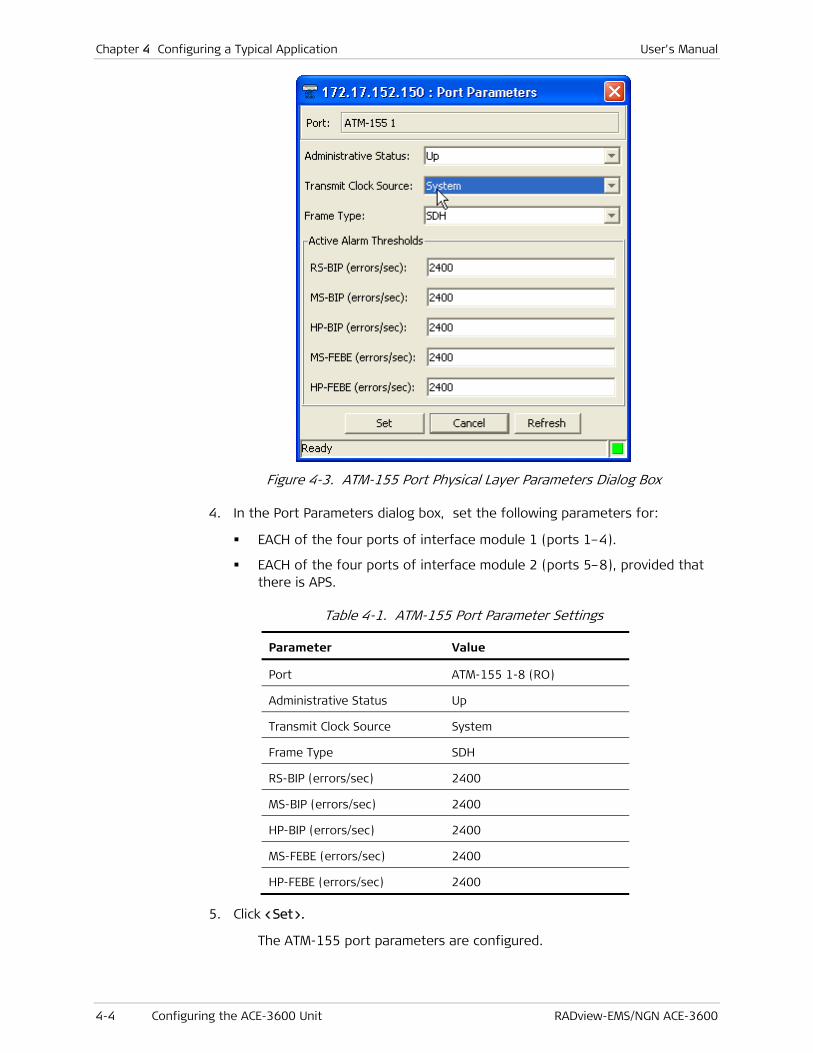
Chapter 4 Configuring a Typical Application User's Manual
4-4 Configuring the ACE-3600 Unit RADview-EMS/NGN ACE-3600
Figure 4-3. ATM-155 Port Physical Layer Parameters Dialog Box
4. In the Port Parameters dialog box, set the following parameters for:
EACH of the four ports of interface module 1 (ports 1–4).
EACH of the four ports of interface module 2 (ports 5–8), provided that there is APS.
Table 4-1. ATM-155 Port Parameter Settings
Parameter Value
Port ATM-155 1-8 (RO)
Administrative Status Up
Transmit Clock Source System
Frame Type SDH
RS-BIP (errors/sec) 2400
MS-BIP (errors/sec) 2400
HP-BIP (errors/sec) 2400
MS-FEBE (errors/sec) 2400
HP-FEBE (errors/sec) 2400
5. Click <Set>.
The ATM-155 port parameters are configured.

User's Manual Chapter 4 Configuring a Typical Application
RADview-EMS/NGN ACE-3600 Configuring the ACE-3600 Unit 4-5
Configuring the GbE Ports
To configure the Gigabit Ethernet parameters:
1. Double-click the Gigabit Ethernet port (Gbe 1 or Gbe 2) on the ACE-3600 device image.
The Gigabit Ethernet Port dialog box is displayed.
2. In the Gigabit Ethernet Port dialog box, click the G-ETHERNET layer.
A light blue frame surrounds the G-ETHERNET layer’s label, and the top menu bar becomes available.
Figure 4-4. GbE Port Dialog Box
3. In the GbE Port menu bar, select Configuration>Parameters.
The Gbe Port Parameters dialog box appears.
Figure 4-5. GbE Port Parameters Dialog Box
4. In the Port Parameters dialog box, set the following parameters for:

Chapter 4 Configuring a Typical Application User's Manual
4-6 Configuring the ACE-3600 Unit RADview-EMS/NGN ACE-3600
GbE 1
GbE 2, for redundancy protection (if required)
Table 4-2. GbE Port Parameter Settings
Parameter Value
Port GbE 1, GbE 2 (RO)
Administrative Status Up
Auto Negotiation Enable
Max Capability Advertised 1000BaseT Full Duplex
Output Rate Limit No Limit
5. Click <Set>.
The GbE port parameters are configured.
Configuring the Ethernet Port
To configure the Ethernet parameters:
1. Double-click the Ethernet port (MNG-ETH) on the ACE-3600 device image.
The Ethernet dialog box is displayed.
2. In the Ethernet dialog box, click the ETHERNET layer.
A light blue frame surrounds the ETHERNET layer’s label, and the top menu bar becomes available.
Figure 4-6. MNG-ETH Dialog Box
3. In the Ethernet Port menu bar, select Configuration>Parameters.
The Ethernet Port Parameters dialog box appears.

User's Manual Chapter 4 Configuring a Typical Application
RADview-EMS/NGN ACE-3600 Configuring the ACE-3600 Unit 4-7
Figure 4-7. Ethernet Port Parameters Dialog Box
4. In the Ethernet Port Parameters dialog box, set the following parameters for the MNG-ETH port.
Table 4-3. Ethernet Port Parameter Settings
Parameter Value
Port MNG-ETH (RO)
Administrative Status Up
Auto Negotiation Enable
Default Type 1000BaseT Full Duplex
5. Click <Set>.
The Ethernet port parameters are configured.
Setting the Protection Parameters
The setting of the protection parameters includes:
• Setting System Redundancy
• Setting Ethernet Redundancy
• Setting ATM-155 Port Protection.
Setting System Redundancy
You can set the two main modules (if two are installed) to work in redundancy protection mode (optional).
To set the system redundancy parameters:
1. Click the ACE-3600 graphic device image.

Chapter 4 Configuring a Typical Application User's Manual
4-8 Configuring the ACE-3600 Unit RADview-EMS/NGN ACE-3600
A light blue frame surrounds the device image and the main menu becomes available.
2. From the Configuration menu, select Protection>Main Card Redundancy.
The Main Card Redundancy dialog box is displayed.
Figure 4-8. Main Card Redundancy Dialog Box
3. In the Main Card Redundancy dialog box, set the following parameters:
Table 4-4. Main Card Redundancy Settings
Parameter Value
Card Redundancy On
Default Main Card Card A
Wait to Restore (sec) 5
4. Click <Set>.
The system redundancy is set.
Setting Ethernet Redundancy
You can set a redundancy mode for the Gigabit Ethernet link between ACE-3600 and the PSN equipment (optional).
To configure the Ethernet redundancy:
1. Click the ACE-3600 graphic device image.
A light blue frame surrounds the device image and the main menu becomes available.
2. From the Configuration menu, select Protection>Ethernet Redundancy.
The Ethernet Redundancy table is displayed.
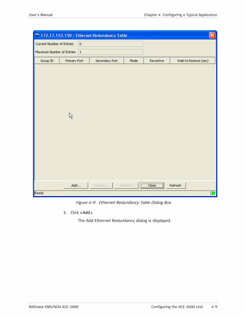
User's Manual Chapter 4 Configuring a Typical Application
RADview-EMS/NGN ACE-3600 Configuring the ACE-3600 Unit 4-9
Figure 4-9. Ethernet Redundancy Table Dialog Box
3. Click <Add>.
The Add Ethernet Redundancy dialog is displayed.

Chapter 4 Configuring a Typical Application User's Manual
4-10 Configuring the ACE-3600 Unit RADview-EMS/NGN ACE-3600
Figure 4-10. Add Ethernet Redundancy Dialog Box
4. In the Add Ethernet Redundancy dialog box, set the following parameters:
Table 4-5. Ethernet Redundancy Parameter Settings
Parameter Value
Group ID 1 (RO)
Primary Port Gbe 1
Secondary Port GbE 2
Mode 1:1
Revertive No
5. Click <Set>.
The Ethernet redundancy is configured.
Setting ATM-155 Port Protection
You can set a protection mode for the STM-1/OC-3c link between ACE-3600 and the RNC (optional).
To configure the APS parameters:
1. Click the ACE-3600 graphic device image.
A light blue frame surrounds the device image and the main menu becomes available.
2. From the Configuration menu, select Protection>APS.
The APS Table dialog box is displayed.

User's Manual Chapter 4 Configuring a Typical Application
RADview-EMS/NGN ACE-3600 Configuring the ACE-3600 Unit 4-11
Figure 4-11. APS Table Dialog Box
3. In the APS Table dialog box, click <Add>.
The Add APS Entry dialog box appears.
Figure 4-12. Add APS Entry Dialog Box
4. In the Add APS Entry dialog box, set the following parameters:
Table 4-6. APS Parameter Settings
Parameter Value
Group ID APS-1
Mode 1+1 Optimized Bi-Directional
Working Port ATM-155 1-4
Protection Port ATM-155 5-8 (in
correspondence to the
working port) (RO)
Wait to Restore (sec) 300

Chapter 4 Configuring a Typical Application User's Manual
4-12 Configuring the ACE-3600 Unit RADview-EMS/NGN ACE-3600
5. Click <Set>.
The APS parameters are configured.
Configuring the Application Parameters
The ACE-3600 application configuration includes:
• Configuring the Router Parameters
• Configuring the Traffic Descriptors
• Configuring the General Multiservice PW over PSN Parameters
• Configuring the Remote Peer Parameters
• Configuring the Pseudowire Parameters.
Configuring the Router Parameters
To configure the router parameters:
1. Click the ACE-3600 graphic device image.
A light blue frame surrounds the device image and the main menu becomes available.
2. From the Configuration menu, select Router>Interface.
The Router Interfaces Table is displayed.

User's Manual Chapter 4 Configuring a Typical Application
RADview-EMS/NGN ACE-3600 Configuring the ACE-3600 Unit 4-13
Figure 4-13. Router Interfaces Table Dialog Box
3. In the Router Interfaces Table dialog box, click <Add>.
The Add Router Interface dialog box appears.
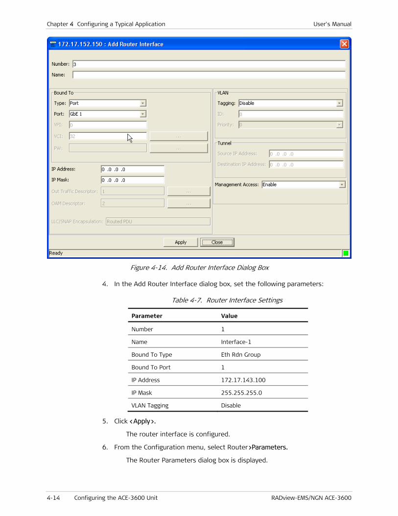
Chapter 4 Configuring a Typical Application User's Manual
4-14 Configuring the ACE-3600 Unit RADview-EMS/NGN ACE-3600
Figure 4-14. Add Router Interface Dialog Box
4. In the Add Router Interface dialog box, set the following parameters:
Table 4-7. Router Interface Settings
Parameter Value
Number 1
Name Interface-1
Bound To Type Eth Rdn Group
Bound To Port 1
IP Address 172.17.143.100
IP Mask 255.255.255.0
VLAN Tagging Disable
5. Click <Apply>.
The router interface is configured.
6. From the Configuration menu, select Router>Parameters.
The Router Parameters dialog box is displayed.

User's Manual Chapter 4 Configuring a Typical Application
RADview-EMS/NGN ACE-3600 Configuring the ACE-3600 Unit 4-15
Figure 4-15. Router Parameters Dialog Box
7. In the Router Parameters dialog box, set the following Default Gateway parameters:
Table 4-8. Default Gateway Settings
Parameter Value
Router Interface 1
IP address 172.17.143.1
8. Click <Set>.
The Router Default Gateway parameters are configured.
Configuring the Traffic Descriptors
To configure the traffic descriptors:
1. Click the ACE-3600 graphic device image.
A light blue frame surrounds the device image and the main menu becomes available.
2. From the Configuration menu, select ATM>Traffic Descriptor.
The Traffic Descriptor table appears.

Chapter 4 Configuring a Typical Application User's Manual
4-16 Configuring the ACE-3600 Unit RADview-EMS/NGN ACE-3600
Figure 4-16. Traffic Descriptor Table Dialog Box
3. In the Traffic Descriptor Table dialog box, click <Add>.
The Add Traffic Descriptor dialog box is displayed.
Figure 4-17. Add Traffic Descriptor Dialog Box
4. In the Add Traffic Descriptor dialog box, set the following VPoPSN parameters:
Table 4-9. VPoPSN Traffic Descriptor Settings
Parameter Value
Index 2
Service category CBR

User's Manual Chapter 4 Configuring a Typical Application
RADview-EMS/NGN ACE-3600 Configuring the ACE-3600 Unit 4-17
Parameter Value
Mode Scheduling
PCR (cell/sec) 3000
CDVT (μsec) 1
5. Click <Apply>.
The VPoPSN traffic descriptor parameters are saved.
6. In the Add Traffic Descriptor dialog box, set the following VCoPSN parameters:
Table 4-10. VCoPSN Traffic Descriptor Settings
Parameter Value
Index 3
Service Category CBR
Mode Scheduling
PCR (cell/sec) 6000
CDVT (μsec) 1
7. Click <Apply>.
The VCoPSN traffic descriptor parameters are saved.
Configuring the Multiservice over PSN Parameters
To configure the multiservice over PSN parameters:
1. Click the ACE-3600 graphic device image.
A light blue frame surrounds the device image and the main menu becomes available.
2. From the Configuration menu, select Multi Service over PSN>General>ATM.
The ATM Parameters dialog box is displayed.
Figure 4-18. Multiservice over PSN Dialog Box
3. In the ATM Parameters dialog box, set the following parameters:

Chapter 4 Configuring a Typical Application User's Manual
4-18 Configuring the ACE-3600 Unit RADview-EMS/NGN ACE-3600
Table 4-11. ATM Multiservice over PSN Settings
Parameter Value
Misorder Window Size
(packets)
8
Reordering Enable
4. Click <Set>.
The general multiservice over PSN parameters are configured.
Configuring the Remote Peer Parameters
To configure the peer parameters for the remote ACE-3600:
1. Click the ACE-3600 graphic device image.
A light blue frame surrounds the device image and the main menu becomes available.
2. From the Configuration menu, select Multi Service over PSN>Peer.
The Peer Table is displayed.
Figure 4-19. Peer Table Dialog Box
3. In the Peer Table dialog box, click <Add>.
The Add Peer dialog box appears.
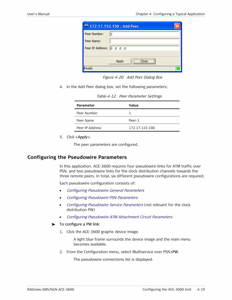
User's Manual Chapter 4 Configuring a Typical Application
RADview-EMS/NGN ACE-3600 Configuring the ACE-3600 Unit 4-19
Figure 4-20. Add Peer Dialog Box
4. In the Add Peer dialog box, set the following parameters:
Table 4-12. Peer Parameter Settings
Parameter Value
Peer Number 1
Peer Name Peer-1
Peer IP Address 172.17.143.100
5. Click <Apply>.
The peer parameters are configured.
Configuring the Pseudowire Parameters
In this application, ACE-3600 requires four pseudowire links for ATM traffic over PSN, and two pseudowire links for the clock distribution channels towards the three remote peers. In total, six different pseudowire configurations are required.
Each pseudowire configuration consists of:
• Configuring Pseudowire General Parameters
• Configuring Pseudowire PSN Parameters
• Configuring Pseudowire Service Parameters (not relevant for the clock distribution PW)
• Configuring Pseudowire ATM Attachment Circuit Parameters.
To configure a PW link:
1. Click the ACE-3600 graphic device image.
A light blue frame surrounds the device image and the main menu becomes available.
2. From the Configuration menu, select Multiservice over PSN>PW.
The pseudowire connections list is displayed.

Chapter 4 Configuring a Typical Application User's Manual
4-20 Configuring the ACE-3600 Unit RADview-EMS/NGN ACE-3600
Figure 4-21. Pseudo Wire Table Dialog Box
Configuring Pseudowire General Parameters
To configure the PW general parameters:
1. In the Pseudowire Table dialog box (see Figure 4-21), click <Add>.
The Add Pseudowire – General Parameters dialog box appears.

User's Manual Chapter 4 Configuring a Typical Application
RADview-EMS/NGN ACE-3600 Configuring the ACE-3600 Unit 4-21
Figure 4-22. Add Pseudowire General Parameters Dialog Box
2. In the Add Pseudowire General Parameters dialog box, set the general parameters for each PW link, according to the tables below.
Configuring Pseudowire PSN Parameters
To configure the PW PSN parameters:
1. In the Add Pseudowire General Parameters dialog box, click <Next>.
The Add Pseudowire PSN Parameters dialog box is displayed.

Chapter 4 Configuring a Typical Application User's Manual
4-22 Configuring the ACE-3600 Unit RADview-EMS/NGN ACE-3600
Figure 4-23. Add Pseudowire PSN Parameters Dialog Box
2. In the Add Pseudowire PSN Parameters dialog box, set the PSN parameters for each PW link, according to the tables below.
Configuring Pseudowire Service Parameters
To configure the PW Service parameters:
1. In the Add Pseudowire PSN Parameters dialog box, click <Next>.
The Add Pseudowire Service Parameters dialog box is displayed, displaying ATM service parameters, depending on the PW type.

User's Manual Chapter 4 Configuring a Typical Application
RADview-EMS/NGN ACE-3600 Configuring the ACE-3600 Unit 4-23
Figure 4-24. Add Pseudowire Service Parameters Dialog Box
2. In the Add Pseudowire Service Parameters dialog box, set the service parameters for each PW link, according to the tables below.
3. Click <Finish>.
The pseudowire general, PSN, and service parameters are saved.
For an ATM PW, save the parameters before you enter the attachment circuit parameters (next step). The attachment circuit parameters can then be saved separately.
Note

Chapter 4 Configuring a Typical Application User's Manual
4-24 Configuring the ACE-3600 Unit RADview-EMS/NGN ACE-3600
Configuring ATM Attachment Circuit Parameters
To configure the PW ATM attachment circuit parameters:
1. In the Pseudowire Table dialog box (see Figure 4-21), click <ATM Attachment Circuits>.
The ATM Attachment Circuits Table dialog box appears, displaying attachment circuit parameters for ATM PW.
Figure 4-25. ATM Attachment Circuits Table Dialog Box
2. In the ATM Attachment Circuit dialog box (see Figure 4-25), click <Add>.
The Add ATM Attachment Circuit dialog box is displayed.
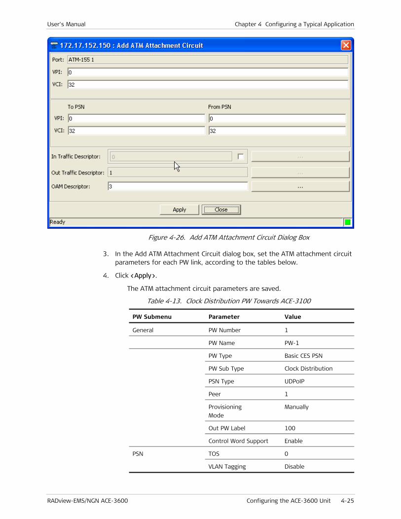
User's Manual Chapter 4 Configuring a Typical Application
RADview-EMS/NGN ACE-3600 Configuring the ACE-3600 Unit 4-25
Figure 4-26. Add ATM Attachment Circuit Dialog Box
3. In the Add ATM Attachment Circuit dialog box, set the ATM attachment circuit parameters for each PW link, according to the tables below.
4. Click <Apply>.
The ATM attachment circuit parameters are saved.
Table 4-13. Clock Distribution PW Towards ACE-3100
PW Submenu Parameter Value
General PW Number 1
PW Name PW-1
PW Type Basic CES PSN
PW Sub Type Clock Distribution
PSN Type UDPoIP
Peer 1
Provisioning
Mode
Manually
Out PW Label 100
Control Word Support Enable
PSN TOS 0
VLAN Tagging Disable

Chapter 4 Configuring a Typical Application User's Manual
4-26 Configuring the ACE-3600 Unit RADview-EMS/NGN ACE-3600
Table 4-14. Data PW for VP (100)
PW Submenu Parameter Value
General PW Number 2
PW Name PW-2
PW Type ATM VP N to 1
PSN Type MPLSoIP
Peer 1
Provisioning
Mode
Manually
Out PW Label 101
In PW Label 101
Control Word Support Enable
Sequence Number
Support
Enable
TX Queue 4 (Low)
OAM Mode Enable
PSN TOS 0
EXP Bits 0
VLAN Tagging Disable
Service Max cells Concatenation 5
Timeout Mode Enable
Timeout (μsec) 100
AAL5 Mode Disable
Attachment circuit Port ATM-155 1
VPI 100
VPI to PSN 100
VPI from PSN 100
Traffic Descriptor 2
OAM Descriptor 3
Table 4-15. Data PW for VC (0/100)
PW Submenu Parameter Value
General PW Number 3
PW Name PW-3
PW Type ATM VC N to 1
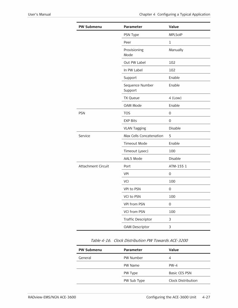
User's Manual Chapter 4 Configuring a Typical Application
RADview-EMS/NGN ACE-3600 Configuring the ACE-3600 Unit 4-27
PW Submenu Parameter Value
PSN Type MPLSoIP
Peer 1
Provisioning
Mode
Manually
Out PW Label 102
In PW Label 102
Support Enable
Sequence Number
Support
Enable
TX Queue 4 (Low)
OAM Mode Enable
PSN TOS 0
EXP Bits 0
VLAN Tagging Disable
Service Max Cells Concatenation 5
Timeout Mode Enable
Timeout (μsec) 100
AAL5 Mode Disable
Attachment Circuit Port ATM-155 1
VPI 0
VCI 100
VPI to PSN 0
VCI to PSN 100
VPI from PSN 0
VCI from PSN 100
Traffic Descriptor 3
OAM Descriptor 3
Table 4-16. Clock Distribution PW Towards ACE-3200
PW Submenu Parameter Value
General PW Number 4
PW Name PW-4
PW Type Basic CES PSN
PW Sub Type Clock Distribution

Chapter 4 Configuring a Typical Application User's Manual
4-28 Configuring the ACE-3600 Unit RADview-EMS/NGN ACE-3600
PW Submenu Parameter Value
PSN Type UDPoIP
Peer 2
Provisioning
Mode
Manually
Out PW Label 100
Control Word Support Enable
PSN TOS 0
VLAN Tagging Disable
Table 4-17. Data PW for VP (200)
PW Submenu Parameter Value
General PW Number 5
PW Name PW-5
PW Type ATM VP N to 1
PSN Type MPLSoIP
Peer 2
Provisioning
Mode
Manually
Out PW Label 201
In PW Label 201
Support Enable
Sequence Number
Support
Enable
TX Queue 4 (Low)
OAM Mode Enable
PSN TOS 0
EXP Bits 0
VLAN Tagging Disable
Service Max Cells Concatenation 5
Timeout Mode Enable
Timeout (μsec) 100
AAL5 Mode Disable
Attachment Circuit Port ATM-155 1
VPI 200
VPI to PSN 200

User's Manual Chapter 4 Configuring a Typical Application
RADview-EMS/NGN ACE-3600 Configuring the ACE-3600 Unit 4-29
PW Submenu Parameter Value
VPI from PSN 200
Traffic Descriptor 2
OAM Descriptor 3
Table 4-18. Data PW for VC (0/200)
PW Submenu Parameter Value
General PW Number 6
PW Name PW-6
PW Type ATM VC N to 1
PSN Type MPLSoIP
Peer 2
Provisioning
Mode
Manually
Out PW Label 202
In PW Label 202
Control Word Support Enable
Sequence Number
Support
Enable
TX Queue 4 (Low)
OAM Mode Enable
PSN TOS 0
EXP Bits 0
VLAN Tagging Disable
Service Max Cells Concatenation 5
Timeout Mode Enable
Timeout (μsec) 100
AAL5 Mode Disable
Attachment Circuit Port ATM-155 1
VPI 0
VCI 200
VPI to PSN 0
VCI to PSN 200
VPI from PSN 0
VCI from PSN 200
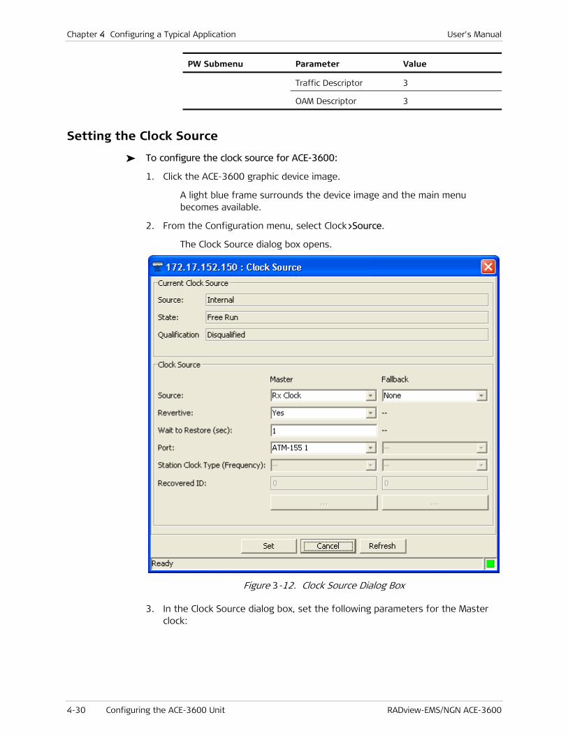
Chapter 4 Configuring a Typical Application User's Manual
4-30 Configuring the ACE-3600 Unit RADview-EMS/NGN ACE-3600
PW Submenu Parameter Value
Traffic Descriptor 3
OAM Descriptor 3
Setting the Clock Source
To configure the clock source for ACE-3600:
1. Click the ACE-3600 graphic device image.
A light blue frame surrounds the device image and the main menu becomes available.
2. From the Configuration menu, select Clock>Source.
The Clock Source dialog box opens.
Figure 3-12. Clock Source Dialog Box
3. In the Clock Source dialog box, set the following parameters for the Master clock:

User's Manual Chapter 4 Configuring a Typical Application
RADview-EMS/NGN ACE-3600 Configuring the ACE-3600 Unit 4-31
Table 4-19. Setting Master Clock Parameters
Parameter Value
Source RX Clock
Port ATM-155 1
4. In the Clock Source dialog box, set the following parameters for the Fallback clock:
Table 4-20. Setting Fallback Clock Parameters
Parameter Value
Source RX Clock
Port ATM-155 5
5. Click <Set>.
The clock source parameters are configured.
Defining the Manager IP Address
To define the manager IP address:
1. Click the ACE-3600 graphic device image.
A light blue frame surrounds the device image.
2. From the main menu, select Options>Manager List.
The Manager List dialog box is displayed.
Figure 4-27. Manager List Dialog Box
3. In the Manager List dialog box, click <Add>.

Chapter 4 Configuring a Typical Application User's Manual
4-32 Configuring the ACE-3600 Unit RADview-EMS/NGN ACE-3600
The Add Manager dialog box is displayed.
Figure 4-28. Add Manager Dialog Box
4. In the Add Manager dialog box, set the following parameter:
Table 4-21. Setting Manager IP Address
Parameter Value
Manager IP address 172.17.143.50
5. Click <Mask Traps> to define the mask traps for this manager.
The Mask Traps dialog box appears.
Figure 4-29. Mask Traps Dialog Box

User's Manual Chapter 4 Configuring a Typical Application
RADview-EMS/NGN ACE-3600 Configuring the ACE-3600 Unit 4-33
6. In the Mask Traps dialog box, set the following parameter:
Table 4-22. Setting Manager Masking Mode
Parameter Value
Masking Mode Manual
7. Click <OK>.
The Add Manager dialog box returns.
8. In the Add Manager dialog box, click <Set>.
The manager parameters are configured.

Chapter 4 Configuring a Typical Application User's Manual
4-34 Configuring the ACE-3600 Unit RADview-EMS/NGN ACE-3600

RADview-EMS/NGN ACE-3600 Introduction 5-1
Chapter 5
Performance Management This chapter describes the various options for monitoring the performance of ACE-3600. The chapter first discusses the ways of viewing the statistics, and then the details of the statistics that can be viewed.
This chapter includes the following sections:
• Introduction
• Viewing APS Statistics
• Viewing ATM XC Statistics
• Viewing the ATM-155 Port Physical Layer Statistics
• Viewing the ATM-155 Port Logical Layer Statistics
• Monitoring the Gigabit Ethernet (GbE) Port
• Monitoring the Ethernet Port
• Monitoring Multiservice over PSN Traffic
• Monitoring LDP
• Viewing the Installed License Status
• Viewing the Syslog Statistics.
5.1 Introduction
This section provides an introduction to:
• Statistical Tables and Graphs
• Graph Characteristics
• Setting the Polling Interval.
Statistical Tables and Graphs
The statistics dialog boxes display both visual and numerical information, in graphs and tables.
RADview ACE-3600 provides two types of statistics:
• Current statistics – Statistical information regarding the current interval.
• Intervals statistics – Statistical information regarding the last six hours (24 intervals of 15 minutes each).
These two types of statistics are displayed in dialog boxes that include:

Chapter 5 Performance Management User's Manual
5-2 Introduction RADview-EMS/NGN ACE-3600
• Title bar – Displays the host selection name and address, graph name, and the current date and time (Agent time).
• Object/parameter fields – The objects and parameters for which the statistical information appears.
• Graph – Customizable colored graph that represents the statistical information, including an explanatory legend of the graph colors.
• Numerical data – Displayed in a table that summarizes the parameter values of the statistical report.
• Common buttons:
Poll – When clicked, ACE-3600 retrieves the most current information and refreshes the displayed statistics accordingly. The button is available only for the current dialog box, and is useful when the interval polling is long. When the polling takes place, the button is temporarily disabled.
Close – Closes the statistics dialog box.
• Status Bar – Indicates the SNMP status in the format: "<x> sec. to next polling", where x is the number of seconds remaining until the next polling.
Graph Characteristics
The graph characteristics described in this section are:
• Vertical Axis Scale
• Horizontal Axis
• Interval Date and Time
• Number of Displayed Polls
• Customizing the Appearance of Graph Lines
• Numerical Value Tooltip.
Vertical Axis Scale
The vertical axis is dynamic and displays the highest value of the displayed parameters. When you hide some parameters, both the scale and the highest value change accordingly.
Horizontal Axis
• Current graph – For the current graph, the horizontal axis represents the time elapsed. When you open the graph, the horizontal axis range of values is the minimum time elapsed in seconds. You can select a different polling interval value to refresh the graph automatically at every interval, as required. The default polling interval value is 10 seconds.
• Intervals graph – The graph displays the interval. The most recent interval appears on the right side of the horizontal axis, while the earliest interval appears at the origin (left side) of the horizontal axis.

User's Manual Chapter 5 Performance Management
RADview-EMS/NGN ACE-3600 Introduction 5-3
.
• The value at the start point of the horizontal axis is not displayed.
• If there is not enough space for displaying time labels for each interval, only some of the intervals are designated with the time label, while the others are only designated with dots.
Interval Date and Time
For interval statistics, the start time is set according to the NMS (Network Management Station) clock. If the NMS and Agent clocks are not synchronized, it can result in different interval start times in the ASCII terminal and the NMS.
You can synchronize the NMS and Agent clocks by using either the Net Date and Time or the Date and Time auto-mode shell application. The time synchronization takes effect only after the current interval period is concluded.
Number of Displayed Polls
You can define the number of displayed polls as a function of the polling interval. The number (n) of displayed polls is calculated as follows:
(n) = 900 / polls per second + 1 + 30 optional manual polls
If you perform more than 30 manual polls, the earliest polls are discarded.
Customizing the Appearance of Graph Lines
ACE-3600 allows you to customize the appearance of lines that appear in the graph.
To display or hide a specific line in the graph:
• Click the line’s legend parameter.
If the selected parameter is the only one in the legend, its graph line cannot be hidden.
To modify the appearance of a graph legend" line:
1. Right-click the line’s legend parameter.
The line appearance options pop-up menu appears.
2. From the pop-up menu, select the appearance option that you want to implement on the parameter’s graph line (see Table 5-1).
Note
Note
Note

Chapter 5 Performance Management User's Manual
5-4 Introduction RADview-EMS/NGN ACE-3600
Table 5-1. Graph Line Appearance Options
Option Description Remark
Bold Turns the graph line of the selected legend
parameter to a bold line.
Only one bold line can appear in the graph at a
time. Therefore, when a newly selected
parameter’s line becomes bold, the previously bold
line becomes regular.
Selecting Bold also causes an invisible graph line to
become visible in bold.
This option is disabled for
a parameter that is
already bold.
Normal Turns the graph line of the selected parameter to
regular (if it was bold).
Normal also causes an invisible parameter to
become visible in regular fonts.
This option is disabled for
a parameter that is
already normal.
Invisible Turns the graph line to invisible. This option is disabled if
the selected parameter is
already invisible, or if it is
the only visible parameter
in the legend list.
Hide Others Turns all the parameters except for the selected
one, to invisible.
If after this operation you select Normal or Bold
for another parameter, both parameters will be
displayed while all the others will remain invisible.
This option is disabled if
the selected parameter is
invisible or if it is the only
one visible.
Show All Causes all the graph lines to be displayed.
This option is useful when some parameters are
hidden and you want to make them all visible.
Numerical Value Tooltip
When the mouse pointer is placed over the dots representing a certain sample, or when it is very close to it, a tooltip appears on the top-left side of the sample point, displaying the point’s vertical axis numerical value.
Setting the Polling Interval
Use the polling interval option to specify the frequency by which the statistics data is refreshed.
To set the polling interval:
1. Click the ACE-3600 graphic device image.
A light blue frame surrounds the device image.
2. From the Statistics menu, select Polling Interval.

User's Manual Chapter 5 Performance Management
RADview-EMS/NGN ACE-3600 Introduction 5-5
Figure 5-1. Statistics Menu
The Polling Interval dialog box appears.
Figure 5-2. Polling Interval Dialog Box
3. Enter the required polling interval, either by typing a value or by using the arrows, and then click <Set>.
Table 5-2. Polling Interval Parameters
Parameter Description Possible Values (RW)
Polling Interval (sec)
The amount of time that
passes between two
sequential polls.
5–60, in increments of 5
Default: 10
• Changing the polling interval affects all current statistics dialog boxes, for all levels and ports.
• The new polling interval takes effect only after the next automatic polling occurs, or after you click <Refresh> in a statistics dialog box.
• The NMS checks if you typed a polling interval that is out of range, and if so, displays an error-message in the status-bar: “Polling Interval: value range is 5…60 in steps of 5.”. Set won’t be performed.
Note
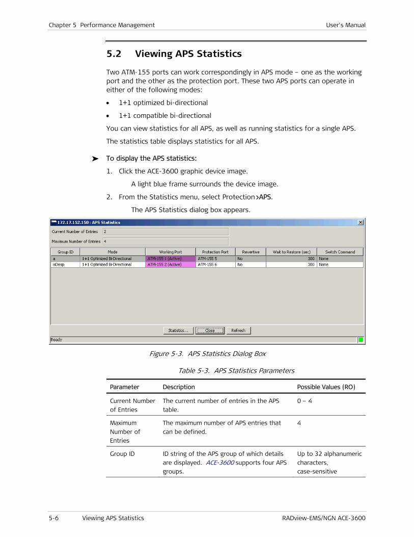
Chapter 5 Performance Management User's Manual
5-6 Viewing APS Statistics RADview-EMS/NGN ACE-3600
5.2 Viewing APS Statistics
Two ATM-155 ports can work correspondingly in APS mode – one as the working port and the other as the protection port. These two APS ports can operate in either of the following modes:
• 1+1 optimized bi-directional
• 1+1 compatible bi-directional
You can view statistics for all APS, as well as running statistics for a single APS.
The statistics table displays statistics for all APS.
To display the APS statistics:
1. Click the ACE-3600 graphic device image.
A light blue frame surrounds the device image.
2. From the Statistics menu, select Protection>APS.
The APS Statistics dialog box appears.
Figure 5-3. APS Statistics Dialog Box
Table 5-3. APS Statistics Parameters
Parameter Description Possible Values (RO)
Current Number
of Entries
The current number of entries in the APS
table.
0 – 4
Maximum
Number of
Entries
The maximum number of APS entries that
can be defined.
4
Group ID ID string of the APS group of which details
are displayed. ACE-3600 supports four APS
groups.
Up to 32 alphanumeric
characters,
case-sensitive
User's Manual Chapter 5 Performance Management
RADview-EMS/NGN ACE-3600 Viewing APS Statistics 5-7
Parameter Description Possible Values (RO)
Mode The APS operation mode. 1+1 Optimized
Bidirectional
1+1 Compatible Bi-
Directional
Working Port The APS working port ATM-155 1-4 (Active)
Protection Port The APS protection port. This port is
automatically selected if APS is enabled on
the working port.
ATM-155 5-8
Revertive If 'Revertive' is enabled ('Yes' is selected),
the port protection switching is reverted
back to the primary link as it was before the
link failure, since the primary link is up
again. The reverting is performed once the
WTR time is concluded (see below).
Yes
No
Default: No
Wait to Restore
(sec)
In APS mode, Wait to Restore (WTR) is the
set delay time required before the primary
port returns to normal operation, once the
port becomes available after recovering
from an error.
This parameter cannot be changed
dynamically (on-the-fly)..
1 – 720
Default: 300

Chapter 5 Performance Management User's Manual
5-8 Viewing APS Statistics RADview-EMS/NGN ACE-3600
Parameter Description Possible Values (RO)
Switch
Command –
options
available for
the 1+1
Optimized
Bi-Directional
APS mode
The APS port switching command. Available
only if the APS mode is enabled (if an APS
group ID exists).
There are four possible switch commands in
the 1+1 optimized bi-directional mode:
• None – the initial state, if no command
was applied since the unit's initialization.
• Force Switch – the service is switched
from the primary port to the secondary
port. Can be selected only when None or
Clear is the current state.
• Lockout –freezes the transmitted K-
bytes and the selector's position (the
traffic is taken from the port which is
currently primary) until the lockout is
cleared. Lockout is considered a local
request that is not signaled over the K-
bytes. Can be selected only when None
or Clear is the current state.
• Clear – clears the current command
(Force Switch or Lockout). If the
'Lockout' command is cleared, the
selector and the transmitted K-bytes
return to their previous state. If the
'Force Switch' command is cleared, the
primary line returns to be the currently
active line, and the local request for
lockout is cleared.
None
Force Switch
Lockout
Clear
Default: None

User's Manual Chapter 5 Performance Management
RADview-EMS/NGN ACE-3600 Viewing APS Statistics 5-9
Parameter Description Possible Values (RO)
Switch
Command –
options
available for
the 1+1
Compatible
Bi-Directional
APS mode
The APS port switching command. Available
only if the APS mode is enabled (if an APS
group ID exists).
There are four possible switch commands in
the 1+1 compatible bi-directional mode:
• None – the initial state, if no command
was applied since the unit's initialization.
• Force Switch to Working – switches the
normal traffic from the protection port
to the working port, unless an equal or
higher priority request exists. Since a
forced switch has a higher priority than
SF or SD on a working port, this
command is carried out regardless of the
current condition of the working port.
• Force Switch to Protection – switches
the normal traffic of the working port to
the protection port, unless an equal or
higher priority switch command is in
effect, or if an SF condition exists on the
protection port.
• Manual Switch to Working – switches the
traffic from the protection port back to
the working port, unless an equal or
higher priority request is in effect. Since
a manual switch has lower priority than
SF or SD on a working port, this
command is carried out only if the
working port is not in SF or SD condition.
• Manual Switch to Protection – switches
the traffic from the working port to the
protection port, unless a failure
condition exists on the protection port
or an equal/higher priority switch
command is in effect. The command is
carried out by issuing a manual switch
request for the normal traffic signal.
• Lockout of Protection – denies the
access of all normal traffic signals (as
well as extra traffic signals, if applicable)
to the protection port by issuing a
"Lockout of Protection" request, unless
an equal protection switch command is
in effect.
• Clear – clears all externally initiated
switch commands and the WTR time, on
the node to which the command was
addressed.
Force Switch to
Working
Force Switch to
Protection
Manual Switch to
Working
Manual Switch to
Protection
Lockout of Protection
Clear
Default: None

Chapter 5 Performance Management User's Manual
5-10 Viewing APS Statistics RADview-EMS/NGN ACE-3600
Viewing the APS Running Statistics
The APS Running Statistics displays the statistics for a single APS.
To display the APS running statistics:
• In the APS Statistics dialog box (see Figure 5-3), select an entry, and then click <Statistics>.
The APS Running Statistics dialog box appears.
Figure 5-4. APS Running Statistics Dialog Box
User's Manual Chapter 5 Performance Management
RADview-EMS/NGN ACE-3600 Viewing APS Statistics 5-11
Table 5-4. APS Running Statistics Parameters
Parameter Description Possible Values (RO)
APS Group ID The unique identifier of the configured APS
group.
Only one APS group can be configured.
User selection
Rx K1 K2 Byte
(hex)
The contents of the received K1K2 bytes,
which are exchanged on APS ports.
Hex value
Tx K1 K2 Byte
(hex)
The contents of the transmitted K1K2
bytes, which are exchanged on APS ports.
Hex value
Signal Failures
(SF)
Status: Indicates the existence of signal
failures.
Total Counters: Indicates the number of
signal failures.
Status: On, Off
Total Counters:
number
Signal
Degraded (SD)
Status: Indicates the existence of signal
degradation.
Total Counters: Indicates the number of
signal degradation occurrences.
Status: On, Off
Total Counters:
number
The <Statistics> button is disabled if an entry is not selected.
To close the APS Running Statistics dialog box:
• In the APS Running Statistics dialog box (see Figure 5-4), click <Close>.
The APS Running Statistics dialog box closes.
Closing the APS Statistics Table
To close the APS statistics table:
• In the APS Statistics dialog box (see Figure 5-3), click <Close>.
The APS Statistics dialog box closes.
Refreshing the APS Statistics Table
To update the APS statistics table with current data:
• In the APS Statistics dialog box (see Figure 5-3), click <Refresh>.
The APS statistics table is updated.
Note

Chapter 5 Performance Management User's Manual
5-12 Viewing ATM XC Statistics RADview-EMS/NGN ACE-3600
5.3 Viewing ATM XC Statistics
The ATM Cross Connection (XC) operation statistics consists of three information categories:
• User statistics (see Viewing VC User Statistics)
• OAM statistics (see Viewing VC OAM Statistics)
• OAM loopback statistics (see Viewing VC OAM Loopback Statistics)
In addition, you can search for VC entries and focus the view on endpoint 1 or endpoint 2.
To display the currently defined ATM XCs:
1. Click the ACE-3600 graphic device image.
A light blue frame surrounds the device image.
2. From the Statistics menu, select ATM>XC>ATM.
The ATM Cross Connection Statistics dialog box appears.
Figure 5-5. ATM Cross Connection Statistics Dialog Box
Table 5-5. ATM XC Statistics Parameters
Parameter Description Possible Values
Current Number of
Connections
Number of currently defined cross-connections. 0–1024
Maximum Number of
Connections
Maximum number of possible cross-connections. 1024

User's Manual Chapter 5 Performance Management
RADview-EMS/NGN ACE-3600 Viewing ATM XC Statistics 5-13
Parameter Description Possible Values
Current
Three options are available on this row:
• User – Select this option to display the VC user
current statistics.
• OAM – Select this option to display the VC OAM
current statistics.
• OAM Loopback – Select this option to display
the VS OAM Loopback current statistics.
User
OAM
OAM Loopback
Intervals
Three options are available on this row:
• User – Select this option to display the VC user
interval statistics.
• OAM – Select this option to display the VC OAM
interval statistics.
• OAM Loopback – Select this option to display
the VS OAM Loopback interval statistics.
User
OAM
OAM Loopback
XC ID Unique ID string for the XC. Up to nine
alphanumeric
characters,
case-sensitive
EP-1 Port The channel’s port type and mode. ATM-155 1–8
EP-1 VPI The channel’s VPI (Virtual Path Identifier). 0–255
EP-1 VCI The channel’s VCI (Virtual Channel Identifier). 32–65535
EP-2 Port The channel’s port. ATM-155 1–8
EP-2 VPI Same as for EP1 VPI. Same as for EP1 VPI
EP-2 VCI Same as for EP1 VCI. Same as for EP1 VCI
Type The connection type. VP
VC
• You can click <Next> to display the next XC entries, if available.
• To search for an XC entry, click <Search>.
Viewing VC User Statistics
Two types of statistical information options are available for VC users:
• Current statistics (see Viewing VC User Current Statistics)
• Interval statistics (see Viewing VC User Intervals Statistics)
Viewing VC User Current Statistics
The VC User Current Statistics dialog box displays information on Rx, Tx, and discarded cells. The information appears for endpoint 1 or endpoint 2, according to your selection.
Note
Chapter 5 Performance Management User's Manual
5-14 Viewing ATM XC Statistics RADview-EMS/NGN ACE-3600
To view the VC user current statistics:
1. In the ATM Cross Connection Statistics dialog box (see Figure 5-5), select the VC for which you want to display the current statistics.
2. On the Current row (see Table 5-5), select User.
3. Click <EP1 Statistics> to display the statistics for endpoint 1, or click <EP2 Statistics> to display the statistics for endpoint 2.
The VC User Current Statistics dialog box is displayed.

User's Manual Chapter 5 Performance Management
RADview-EMS/NGN ACE-3600 Viewing ATM XC Statistics 5-15
Figure 5-6. VC User Current Statistics Dialog Box
Table 5-6. VP/VC User Current Statistics Parameters
Parameter Description Possible Values (RO)
Port EP-X port in the selected XC. ATM-155 1–8
VPI EP-X VPI in the selected XC. 0–255
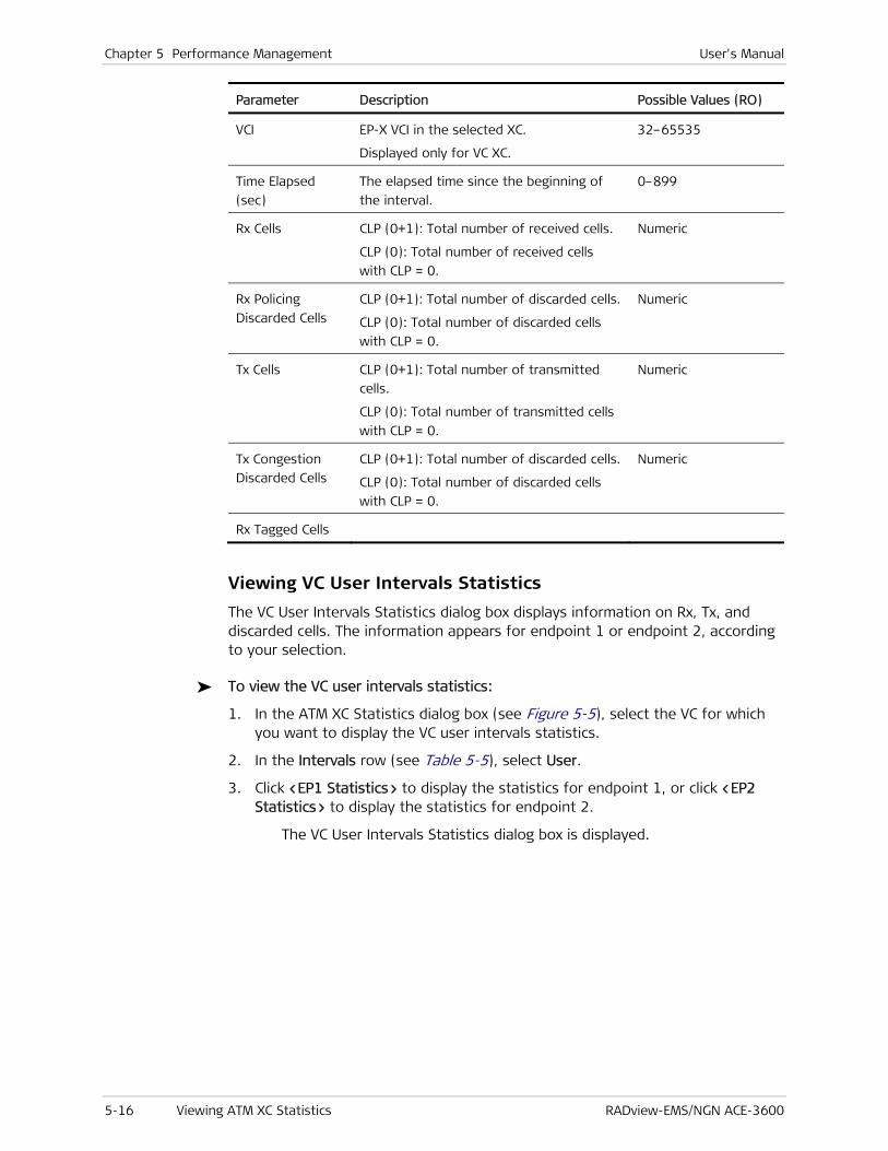
Chapter 5 Performance Management User's Manual
5-16 Viewing ATM XC Statistics RADview-EMS/NGN ACE-3600
Parameter Description Possible Values (RO)
VCI EP-X VCI in the selected XC.
Displayed only for VC XC.
32–65535
Time Elapsed
(sec)
The elapsed time since the beginning of
the interval.
0–899
Rx Cells CLP (0+1): Total number of received cells.
CLP (0): Total number of received cells
with CLP = 0.
Numeric
Rx Policing
Discarded Cells
CLP (0+1): Total number of discarded cells.
CLP (0): Total number of discarded cells
with CLP = 0.
Numeric
Tx Cells CLP (0+1): Total number of transmitted
cells.
CLP (0): Total number of transmitted cells
with CLP = 0.
Numeric
Tx Congestion
Discarded Cells
CLP (0+1): Total number of discarded cells.
CLP (0): Total number of discarded cells
with CLP = 0.
Numeric
Rx Tagged Cells
Viewing VC User Intervals Statistics
The VC User Intervals Statistics dialog box displays information on Rx, Tx, and discarded cells. The information appears for endpoint 1 or endpoint 2, according to your selection.
To view the VC user intervals statistics:
1. In the ATM XC Statistics dialog box (see Figure 5-5), select the VC for which you want to display the VC user intervals statistics.
2. In the Intervals row (see Table 5-5), select User.
3. Click <EP1 Statistics> to display the statistics for endpoint 1, or click <EP2 Statistics> to display the statistics for endpoint 2.
The VC User Intervals Statistics dialog box is displayed.

User's Manual Chapter 5 Performance Management
RADview-EMS/NGN ACE-3600 Viewing ATM XC Statistics 5-17
Figure 5-7. VC User Intervals Statistics Dialog Box
Table 5-7. VC User Intervals Statistics Parameters
Parameter Description Possible Values
Port EP-X port of the selected XC. ATM-155 1–8
VPI EP-X VPI of the selected XC. 0–255
VCI EP-X VPI of the selected XC.
Displayed only for VC XC.
32–65535
Number of Intervals Number of displayed intervals. 0–24
Inv. No. Interval number. 1–24
From (hh:mm) Time at which the interval began. hh:mm
To (hh:mm) Time at which the interval ended. hh:mm
Rx Cells (CLP 0+1) Total number of received cells during the
interval.
Numeric
Rx Cells (CLP 0) Total number of received cells with
CLP=0 during the interval.
Numeric
Rx Policing Discarded
Cells (CLP 0+1)
Total number of discarded cells received
during the interval.
Numeric

Chapter 5 Performance Management User's Manual
5-18 Viewing ATM XC Statistics RADview-EMS/NGN ACE-3600
Parameter Description Possible Values
Rx Policing Discarded
Cells (CLP 0)
Total number of discarded cells with
CLP=0, received during the interval.
Numeric
Rx Tagged Cells Numeric
Tx Cells (CLP 0+1) Total number of transmitted cells during
the interval.
Numeric
Tx Cells (CLP 0) Total number of transmitted cells with
CLP=0 during the interval.
Numeric
Discarded Cells (CLP
0+1)
Total number of discarded cells during
the interval.
Numeric
Discarded Cells
(CLP 0)
Total number of discarded cells with
CLP=0 during the interval.
Numeric
Viewing VC OAM Statistics
Two types of statistical information options are available for VC OAM:
• Current statistics (see Viewing VC OAM Current Statistics)
• Interval statistics (see Viewing VC OAM Intervals Statistics).
Viewing VC OAM Current Statistics
The VC OAM Current Statistics dialog box displays information on the OAM cells current statistics. The information appears for endpoint 1 or endpoint 2, according to your selection.
To view the VC OAM current statistics:
1. In the ATM XC Statistics dialog box (see Figure 5-5), select the VC for which you want to display the current statistics.
2. In the Current row (see Table 5-5), select OAM.
3. Click <EP1 Statistics> to display the statistics for endpoint 1, or click <EP2 Statistics> to display the statistics for endpoint 2.
The VC OAM Current Statistics dialog box is displayed.
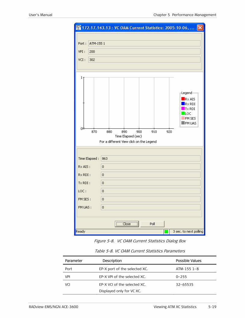
User's Manual Chapter 5 Performance Management
RADview-EMS/NGN ACE-3600 Viewing ATM XC Statistics 5-19
Figure 5-8. VC OAM Current Statistics Dialog Box
Table 5-8. VC OAM Current Statistics Parameters
Parameter Description Possible Values
Port EP-X port of the selected XC. ATM-155 1–8
VPI EP-X VPI of the selected XC. 0–255
VCI EP-X VCI of the selected XC.
Displayed only for VC XC.
32–65535
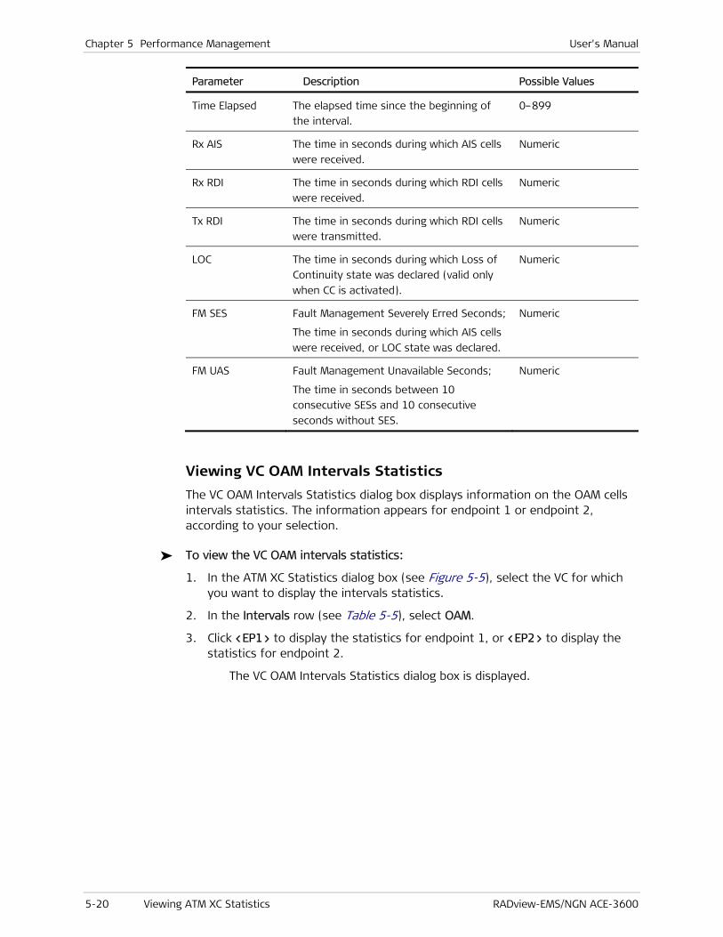
Chapter 5 Performance Management User's Manual
5-20 Viewing ATM XC Statistics RADview-EMS/NGN ACE-3600
Parameter Description Possible Values
Time Elapsed The elapsed time since the beginning of
the interval.
0–899
Rx AIS The time in seconds during which AIS cells
were received.
Numeric
Rx RDI The time in seconds during which RDI cells
were received.
Numeric
Tx RDI The time in seconds during which RDI cells
were transmitted.
Numeric
LOC The time in seconds during which Loss of
Continuity state was declared (valid only
when CC is activated).
Numeric
FM SES Fault Management Severely Erred Seconds;
The time in seconds during which AIS cells
were received, or LOC state was declared.
Numeric
FM UAS Fault Management Unavailable Seconds;
The time in seconds between 10
consecutive SESs and 10 consecutive
seconds without SES.
Numeric
Viewing VC OAM Intervals Statistics
The VC OAM Intervals Statistics dialog box displays information on the OAM cells intervals statistics. The information appears for endpoint 1 or endpoint 2, according to your selection.
To view the VC OAM intervals statistics:
1. In the ATM XC Statistics dialog box (see Figure 5-5), select the VC for which you want to display the intervals statistics.
2. In the Intervals row (see Table 5-5), select OAM.
3. Click <EP1> to display the statistics for endpoint 1, or <EP2> to display the statistics for endpoint 2.
The VC OAM Intervals Statistics dialog box is displayed.

User's Manual Chapter 5 Performance Management
RADview-EMS/NGN ACE-3600 Viewing ATM XC Statistics 5-21
Figure 5-9. VC OAM Intervals Statistics
Table 5-9. VC OAM Intervals Statistics Parameters
Parameter Description Possible Values
Port EP-X port of the selected XC. ATM-155 1–8
VPI EP-X VPI of the selected XC. 0–255
VCI EP-X VCI of the selected XC.
Displayed only for VC XC.
32–65535
Number of Intervals The number of intervals displayed. 0–24
Inv. No. Interval number. 1–24
From The time at which the interval began. Time entry in the
hh:mm format
To The time at which the interval ended. Time entry in the
hh:mm format
Rx AIS The time in seconds during which AIS
cells were received.
Numeric
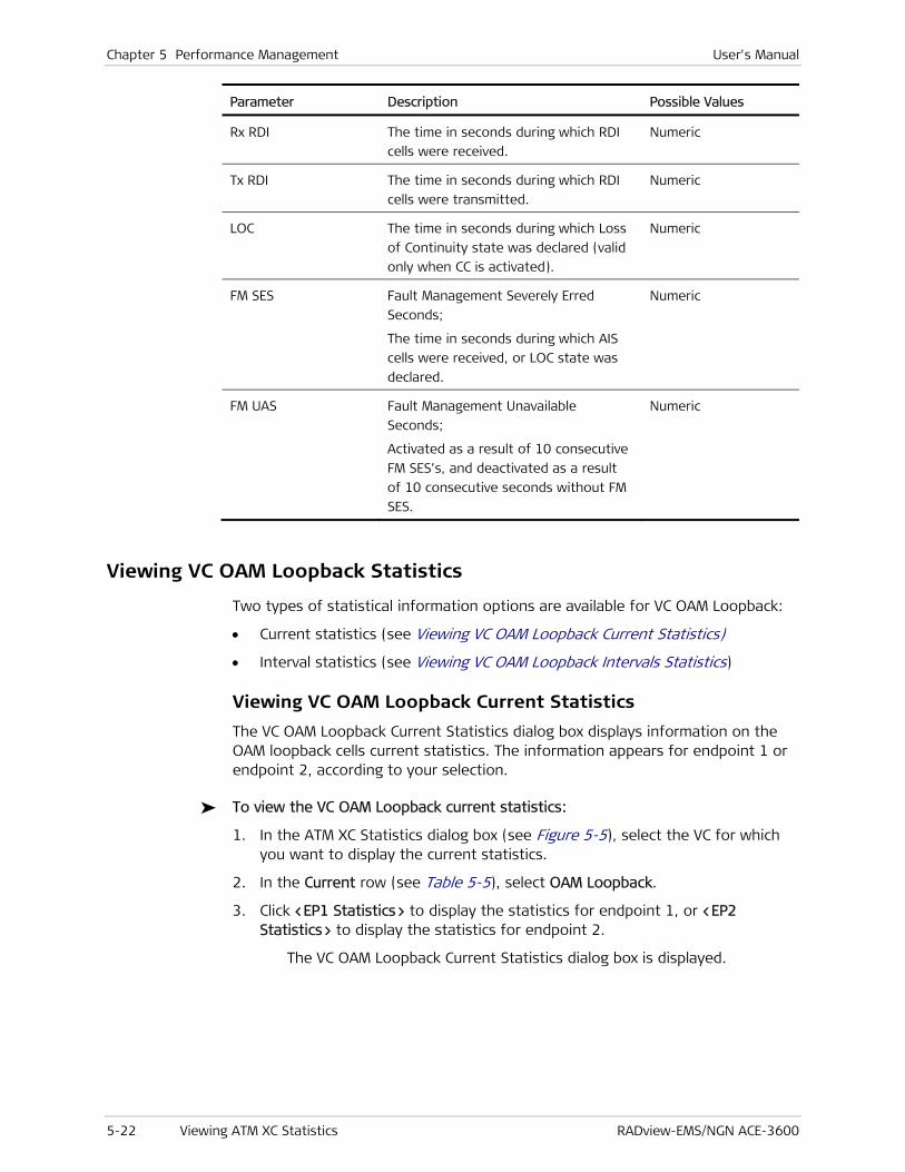
Chapter 5 Performance Management User's Manual
5-22 Viewing ATM XC Statistics RADview-EMS/NGN ACE-3600
Parameter Description Possible Values
Rx RDI The time in seconds during which RDI
cells were received.
Numeric
Tx RDI The time in seconds during which RDI
cells were transmitted.
Numeric
LOC The time in seconds during which Loss
of Continuity state was declared (valid
only when CC is activated).
Numeric
FM SES Fault Management Severely Erred
Seconds;
The time in seconds during which AIS
cells were received, or LOC state was
declared.
Numeric
FM UAS Fault Management Unavailable
Seconds;
Activated as a result of 10 consecutive
FM SES’s, and deactivated as a result
of 10 consecutive seconds without FM
SES.
Numeric
Viewing VC OAM Loopback Statistics
Two types of statistical information options are available for VC OAM Loopback:
• Current statistics (see Viewing VC OAM Loopback Current Statistics)
• Interval statistics (see Viewing VC OAM Loopback Intervals Statistics)
Viewing VC OAM Loopback Current Statistics
The VC OAM Loopback Current Statistics dialog box displays information on the OAM loopback cells current statistics. The information appears for endpoint 1 or endpoint 2, according to your selection.
To view the VC OAM Loopback current statistics:
1. In the ATM XC Statistics dialog box (see Figure 5-5), select the VC for which you want to display the current statistics.
2. In the Current row (see Table 5-5), select OAM Loopback.
3. Click <EP1 Statistics> to display the statistics for endpoint 1, or <EP2 Statistics> to display the statistics for endpoint 2.
The VC OAM Loopback Current Statistics dialog box is displayed.
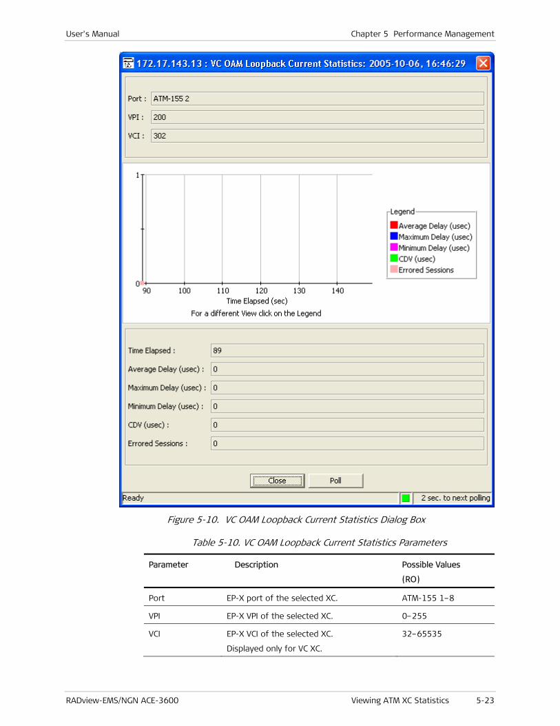
User's Manual Chapter 5 Performance Management
RADview-EMS/NGN ACE-3600 Viewing ATM XC Statistics 5-23
Figure 5-10. VC OAM Loopback Current Statistics Dialog Box
Table 5-10. VC OAM Loopback Current Statistics Parameters
Parameter Description Possible Values
(RO)
Port EP-X port of the selected XC. ATM-155 1–8
VPI EP-X VPI of the selected XC. 0–255
VCI EP-X VCI of the selected XC.
Displayed only for VC XC.
32–65535

Chapter 5 Performance Management User's Manual
5-24 Viewing ATM XC Statistics RADview-EMS/NGN ACE-3600
Parameter Description Possible Values
(RO)
Time Elapsed The elapsed time since the beginning of
the interval.
0–899
Average Delay
(μsec)
The average round-trip delay of the
connection.
Number
Maximum Delay
(μsec)
The maximum round trip delay of the
connection.
Number
Minimum Delay
(μsec)
The minimum round trip delay of the
connection.
Number
CDV (μsec) The cell delay variation measured for the
connection. This parameter is calculated as
the standard deviation of the delay
measurements.
Number
Errored Sessions Number of failed loopback sessions.
A loopback session in which a cell is not
received within five seconds is considered
to have failed.
Number
Viewing VC OAM Loopback Intervals Statistics
The VC OAM Loopback Intervals Statistics dialog box displays information on the OAM loopback cells interval statistics. The information appears for endpoint 1 or endpoint 2, according to your selection.
To view the VC OAM Loopback intervals statistics:
1. In the ATM XC Statistics dialog box (see Figure 5-5), select the VC for which you want to display the intervals statistics.
2. In the Intervals row (see Table 5-5), select OAM Loopback.
3. Click <EP1 Statistics> to display the statistics of endpoint 1, or <EP2 Statistics> to display the statistics of endpoint 2.
The VC OAM Loopback Intervals Statistic dialog box is displayed.
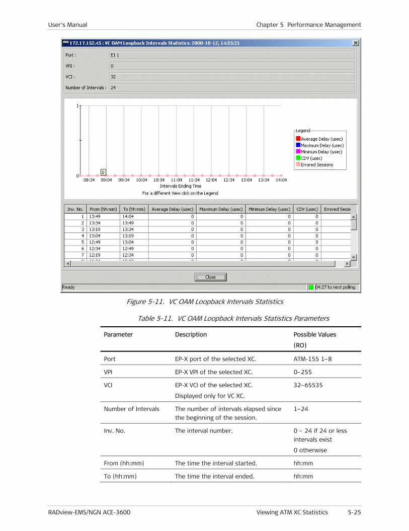
User's Manual Chapter 5 Performance Management
RADview-EMS/NGN ACE-3600 Viewing ATM XC Statistics 5-25
Figure 5-11. VC OAM Loopback Intervals Statistics
Table 5-11. VC OAM Loopback Intervals Statistics Parameters
Parameter Description Possible Values
(RO)
Port EP-X port of the selected XC. ATM-155 1–8
VPI EP-X VPI of the selected XC. 0–255
VCI EP-X VCI of the selected XC.
Displayed only for VC XC.
32–65535
Number of Intervals The number of intervals elapsed since
the beginning of the session.
1–24
Inv. No. The interval number. 0 – 24 if 24 or less
intervals exist
0 otherwise
From (hh:mm) The time the interval started. hh:mm
To (hh:mm) The time the interval ended. hh:mm

Chapter 5 Performance Management User's Manual
5-26 Viewing the ATM-155 Port Physical Layer Statistics RADview-EMS/NGN ACE-3600
Parameter Description Possible Values
(RO)
Average Delay (μsec) The average round trip delay of the
connection.
Number
Maximum Delay (μsec) The maximum round trip delay of the
connection.
Number
Minimum Delay (μsec) The minimum round trip delay of the
connection.
Number
CDV (μsec) The cell delay variation measured for
the connection. This parameter is
calculated as the standard deviation of
the delay measurements.
Number
Errored Sessions The number of failed loopback
sessions.
A loopback session in which a cell is
not received within five seconds is
considered to have failed.
Number
5.4 Viewing the ATM-155 Port Physical Layer Statistics
Two types of statistical information options are available for the physical layer (SONET/SDH) of an ATM-155 port:
• Current statistics (see Viewing the ATM-155 Port Physical Layer Current Statistics)
• Interval statistics (see Viewing the ATM-155 Port Physical Layer Intervals Statistics).
Viewing the ATM-155 Port Physical Layer Current Statistics
To view the ATM-155 port current statistics for the physical layer:
1. Double-click an ATM-155 port in the ACE-3600 graphic device image.
The ATM-155 Port dialog box is displayed.
2. In the ATM-155 Port dialog box, click the SONET/SDH layer rectangle.
A light blue frame surrounds the layer.

User's Manual Chapter 5 Performance Management
RADview-EMS/NGN ACE-3600 Viewing the ATM-155 Port Physical Layer Statistics 5-27
Figure 5-12. ATM-155 Physical Layer Selected
3. From the Statistics menu, select Current.
The Port Current Statistics dialog box is displayed for the SONET/SDH layer.
Figure 5-13. Port Current Statistics – Physical Layer Dialog Box
Table 5-12. Port Current Statistics – Physical Layer Parameters
Parameter Description Possible Values (RO)
Port The port type and number. ATM-155 1–8
Type The port’s frame type. SDH
SONET
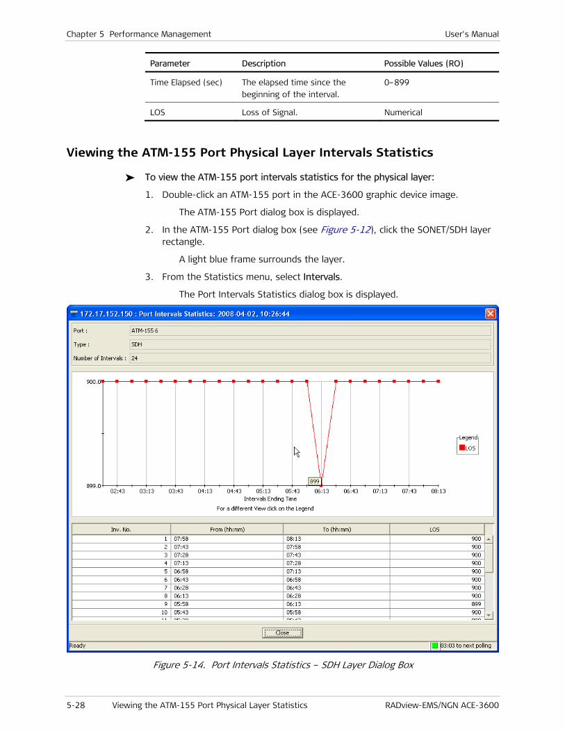
Chapter 5 Performance Management User's Manual
5-28 Viewing the ATM-155 Port Physical Layer Statistics RADview-EMS/NGN ACE-3600
Parameter Description Possible Values (RO)
Time Elapsed (sec) The elapsed time since the
beginning of the interval.
0–899
LOS Loss of Signal. Numerical
Viewing the ATM-155 Port Physical Layer Intervals Statistics
To view the ATM-155 port intervals statistics for the physical layer:
1. Double-click an ATM-155 port in the ACE-3600 graphic device image.
The ATM-155 Port dialog box is displayed.
2. In the ATM-155 Port dialog box (see Figure 5-12), click the SONET/SDH layer rectangle.
A light blue frame surrounds the layer.
3. From the Statistics menu, select Intervals.
The Port Intervals Statistics dialog box is displayed.
Figure 5-14. Port Intervals Statistics – SDH Layer Dialog Box
User's Manual Chapter 5 Performance Management
RADview-EMS/NGN ACE-3600 Viewing the ATM-155 Port Logical Layer Statistics 5-29
Table 5-13. Port Intervals Statistics – SDH Layer Parameters
Parameter Description Possible Values (RO)
Port The port type and number. ATM-155 1–8
Type The port’s frame type. SDH
SONET
Number of
Intervals
Number of recorded intervals. 0–24
Inv. No. Interval number. 1–24
From (hh:mm) Time at which the interval began. Time entry in the
hh:mm format
To (hh:mm) Time at which the interval ended. Time entry in the
hh:mm format
LOS Loss of Signal. Numerical
5.5 Viewing the ATM-155 Port Logical Layer Statistics
Two types of statistical information options are available for the ATM-155 ports’ logical (ATM) layer:
• Current statistics (see Viewing the ATM Layer Current Statistics)
• Interval statistics (see Viewing the ATM Layer Intervals Statistics).
Viewing the ATM Layer Current Statistics
To view the ATM layer current statistics:
1. Double-click an ATM-155 port in the ACE-3600 graphic device image.
The ATM-155 Port dialog box is displayed.
2. In the ATM-155 Port dialog box, click the ATM layer rectangle.
A light blue frame surrounds the layer.

Chapter 5 Performance Management User's Manual
5-30 Viewing the ATM-155 Port Logical Layer Statistics RADview-EMS/NGN ACE-3600
Figure 5-15. ATM-155 Port – ATM Layer Selected
3. From the Statistics menu, select Current.
The Port Current Statistics dialog box appears.

User's Manual Chapter 5 Performance Management
RADview-EMS/NGN ACE-3600 Viewing the ATM-155 Port Logical Layer Statistics 5-31
Figure 5-16. Port Current Statistics - ATM Layer Dialog Box
Table 5-14. Port Current Statistics - ATM Layer Parameters
Parameter Description Possible Values (RO)
Port The port type and number. ATM-155 1–8
Type The port’s frame type. ATM
Time Elapsed
(sec)
The time elapsed since the beginning of the
current interval.
0–899
Tx Cells The number of cells transmitted on the port. Numerical
Rx Cells The number of cells received without HEC Numerical
Chapter 5 Performance Management User's Manual
5-32 Viewing the ATM-155 Port Logical Layer Statistics RADview-EMS/NGN ACE-3600
Parameter Description Possible Values (RO)
error.
Corrected HEC
Cells
The number of frames received with an
erroneous HEC, corrected (single error), and
placed into the device.
Numerical
Uncorrected HEC
Cells
The number of frames received with an
uncorrected HEC error (two or more errors),
and therefore dropped.
Numerical
Viewing the ATM Layer Intervals Statistics
To view the ATM layer intervals statistics:
1. Double-click an ATM-155 port in the ACE-3600 graphic device image.
The ATM-155 Port dialog box is displayed.
2. In the ATM-155 Port dialog box (see Figure 5-15), click the ATM layer rectangle.
A light blue frame surrounds the layer.
3. From the Statistics menu, select Intervals.
The Port Intervals Statistics dialog box is displayed.

User's Manual Chapter 5 Performance Management
RADview-EMS/NGN ACE-3600 Viewing the ATM-155 Port Logical Layer Statistics 5-33
Figure 5-17. Port Intervals Statistics - ATM Layer Dialog Box
Table 5-15. Port Intervals Statistics - ATM Layer Parameters
Parameter Description Possible Values (RO)
Port The port type and number. ATM-155 1–8
Type The port’s frame type. ATM
Number of
Intervals
Number of recorded intervals. 0–24
Inv. No. Interval number. 1–24
From (hh:mm) Time at which the interval began. Time entry in the
hh:mm format
To (hh:mm) Time at which the interval ended. Time entry in the
hh:mm format
Tx Cells Number of cells transmitted on the port. Numerical
Rx Cells Number of cells received without HEC
error.
Numerical

Chapter 5 Performance Management User's Manual
5-34 Monitoring the Gigabit Ethernet (GbE) Ports RADview-EMS/NGN ACE-3600
Parameter Description Possible Values (RO)
Corrected HEC Cells The number of frames received with an
erroneous HEC, corrected (single error),
and returned to the device.
Numerical
Uncorrected HEC
Cells
The number of cells received with an
uncorrected HEC error (two or more
errors), and therefore dropped.
Numerical
5.6 Monitoring the Gigabit Ethernet (GbE) Ports
You can monitor the two GbE ports by:
• Viewing the GbE Port Information
• Viewing the GbE Port Statistics.
Viewing the GbE Port Information
To view the Gigabit Ethernet port information:
1. Double-click the Gigabit Ethernet port (Gbe 1 or Gbe 2) on the ACE-3600 device image.
The Gigabit Ethernet Port dialog box is displayed.
2. Select the G-ETHERNET layer.
A light blue frame surrounds the G-ETHERNET layer’s label, and the top menu bar becomes available.
Figure 5-18. GbE Port Dialog Box
3. From the Configuration menu of the Gigabit Ethernet Port menu bar, select Port Status (see Figure 5-26).
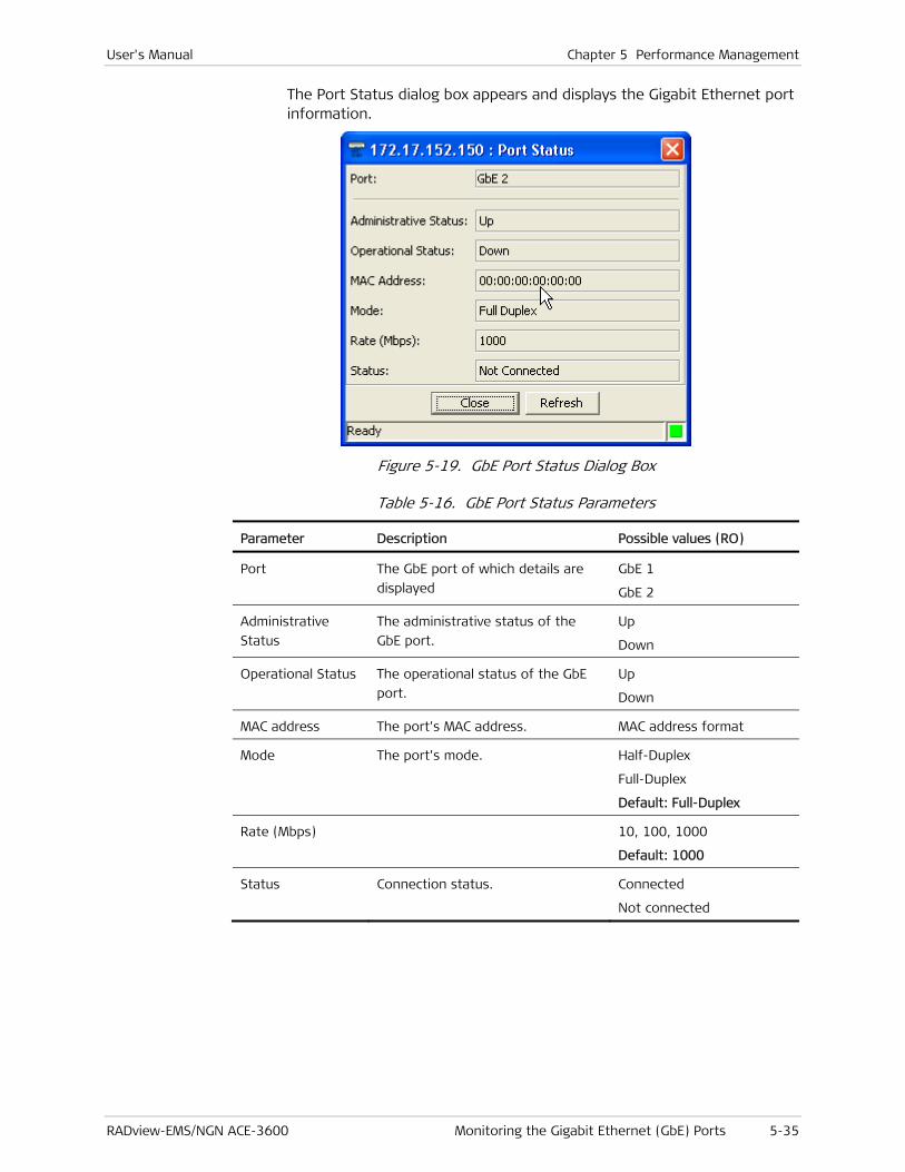
User's Manual Chapter 5 Performance Management
RADview-EMS/NGN ACE-3600 Monitoring the Gigabit Ethernet (GbE) Ports 5-35
The Port Status dialog box appears and displays the Gigabit Ethernet port information.
Figure 5-19. GbE Port Status Dialog Box
Table 5-16. GbE Port Status Parameters
Parameter Description Possible values (RO)
Port The GbE port of which details are
displayed
GbE 1
GbE 2
Administrative
Status
The administrative status of the
GbE port.
Up
Down
Operational Status The operational status of the GbE
port.
Up
Down
MAC address The port’s MAC address. MAC address format
Mode The port’s mode. Half-Duplex
Full-Duplex
Default: Full-Duplex
Rate (Mbps) 10, 100, 1000
Default: 1000
Status Connection status. Connected
Not connected

Chapter 5 Performance Management User's Manual
5-36 Monitoring the Gigabit Ethernet (GbE) Ports RADview-EMS/NGN ACE-3600
Viewing the GbE Port Statistics
You can view the current and interval GbE port statistics, in both the Rx and Tx directions, as described in the following sections:
• Viewing the GbE Current Statistics in the Rx Direction
• Viewing the GbE Current Statistics in the Tx Direction
• Viewing the GbE Intervals Statistics in the Rx Direction
• Viewing the GbE Intervals Statistics in the Tx Direction.
Viewing the GbE Current Statistics in the Rx Direction
To view the GbE current statistics in the Rx direction:
1. Double-click a GbE port in the ACE-3600 graphic device image.
The Gbe Port dialog box is displayed.
2. In the GbE Port dialog box, click the G-Ethernet layer rectangle.
A light blue frame surrounds the layer.
Figure 5-20. GbE Port Selected
3. From the Statistics menu, select Current and then Rx.
The current Rx statistics are displayed

User's Manual Chapter 5 Performance Management
RADview-EMS/NGN ACE-3600 Monitoring the Gigabit Ethernet (GbE) Ports 5-37
Figure 5-21. GbE Port Current RX Statistics
Table 5-17. GbE Current Rx Statistics Parameters
Parameter Description Possible Values
(RO)
Port The name of the GbE port. GbE 1-2
Time Elapsed (sec) Elapsed time (in seconds) since the
beginning of the current interval.
0–899
Correct Frames Number of successfully received frames. Numerical
Correct Bytes Number of successfully received bytes. Numerical
FCS Error Frames Number of received frames that did not
pass the FCS check.
Numerical
Congestion Dropped
Frames
Number of frames that were dropped due
to lack of buffers.
This may be caused by attempting to send
traffic towards the Ethernet connection at
a rate higher than the ATM transmission
Numerical
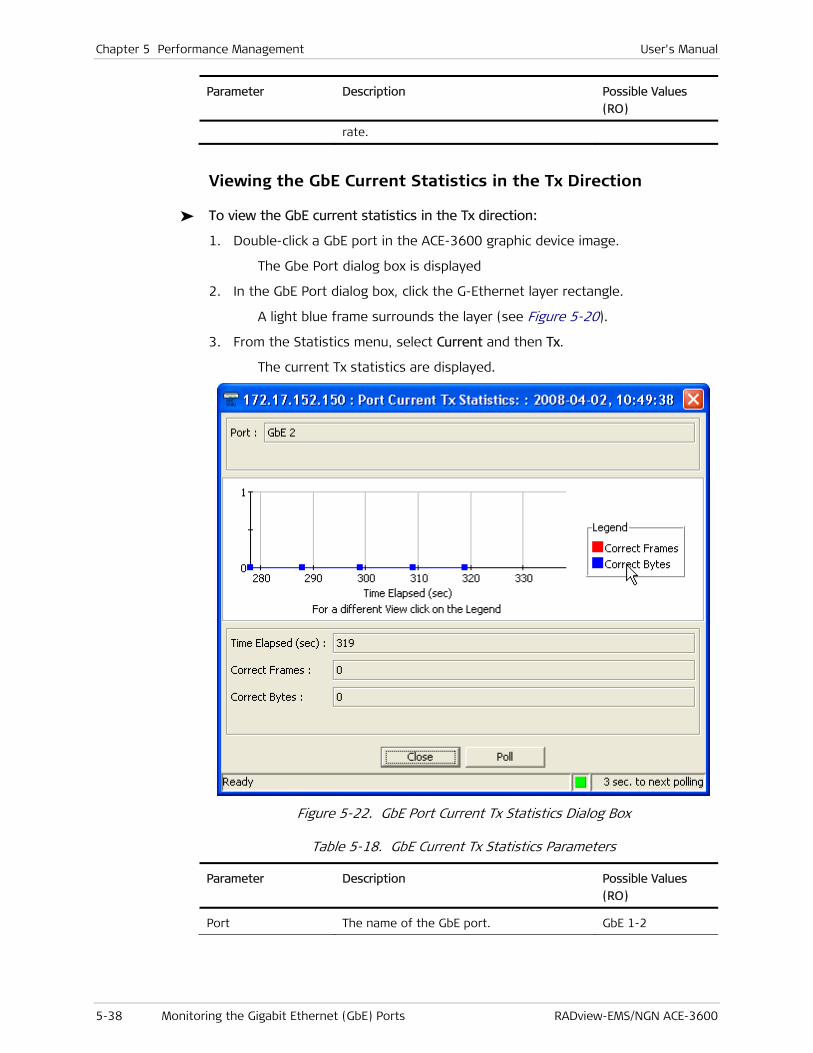
Chapter 5 Performance Management User's Manual
5-38 Monitoring the Gigabit Ethernet (GbE) Ports RADview-EMS/NGN ACE-3600
Parameter Description Possible Values
(RO)
rate.
Viewing the GbE Current Statistics in the Tx Direction
To view the GbE current statistics in the Tx direction:
1. Double-click a GbE port in the ACE-3600 graphic device image.
The Gbe Port dialog box is displayed
2. In the GbE Port dialog box, click the G-Ethernet layer rectangle.
A light blue frame surrounds the layer (see Figure 5-20).
3. From the Statistics menu, select Current and then Tx.
The current Tx statistics are displayed.
Figure 5-22. GbE Port Current Tx Statistics Dialog Box
Table 5-18. GbE Current Tx Statistics Parameters
Parameter Description Possible Values
(RO)
Port The name of the GbE port. GbE 1-2
User's Manual Chapter 5 Performance Management
RADview-EMS/NGN ACE-3600 Monitoring the Gigabit Ethernet (GbE) Ports 5-39
Parameter Description Possible Values
(RO)
Port The name of the GbE port. GbE 1-2
Time Elapsed (sec)
Elapsed time (in seconds) since the
beginning of the current interval.
0–899
Correct Frames Number of successfully transmitted frames. Numerical
Correct Bytes Number of successfully transmitted bytes. Numerical
Viewing the GbE Intervals Statistics in the Rx Direction
To view the GbE intervals statistics in the Rx direction:
1. Double-click a GbE port in the ACE-3600 graphic device image.
The Gbe Port dialog box is displayed (see Figure 5-20).
2. In the GbE Port dialog box, click the G-Ethernet layer rectangle.
A light blue frame surrounds the layer (see Figure 5-20).
3. From the Statistics menu, select Interval and then Rx.
The interval Rx statistics are displayed.

Chapter 5 Performance Management User's Manual
5-40 Monitoring the Gigabit Ethernet (GbE) Ports RADview-EMS/NGN ACE-3600
Figure 5-23. GbE Intervals RX Statistics Dialog Box
Table 5-19. GbE Intervals Rx Statistics Parameters
Parameter Description Possible Values
(RO)
Port The name of the GbE port. GbE 1-2
Number of Intervals Number of recorded intervals. 0–24
Inv. No. Interval number. 1–24
From (hh:mm) Time at which the interval began. Time entry in the
hh:mm format
To (hh:mm) Time at which the interval ended. Time entry in the
hh:mm format
Correct Frames Number of successfully received frames. Numerical
Correct Bytes Number of successfully received bytes. Numerical
FCS Error Frames Number of received frames that did not
pass the FCS check.
Numerical
Congestion Dropped Number of frames that were dropped due Numerical
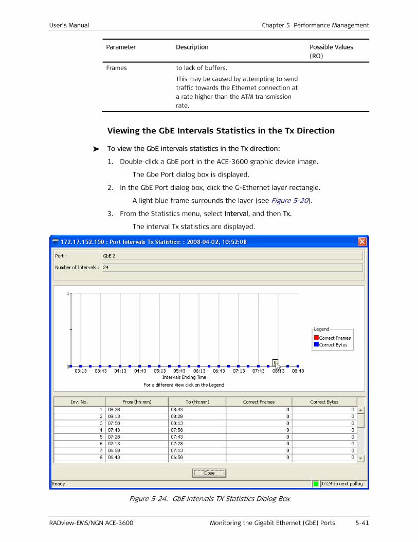
User's Manual Chapter 5 Performance Management
RADview-EMS/NGN ACE-3600 Monitoring the Gigabit Ethernet (GbE) Ports 5-41
Parameter Description Possible Values
(RO)
Frames to lack of buffers.
This may be caused by attempting to send
traffic towards the Ethernet connection at
a rate higher than the ATM transmission
rate.
Viewing the GbE Intervals Statistics in the Tx Direction
To view the GbE intervals statistics in the Tx direction:
1. Double-click a GbE port in the ACE-3600 graphic device image.
The Gbe Port dialog box is displayed.
2. In the GbE Port dialog box, click the G-Ethernet layer rectangle.
A light blue frame surrounds the layer (see Figure 5-20).
3. From the Statistics menu, select Interval, and then Tx.
The interval Tx statistics are displayed.
Figure 5-24. GbE Intervals TX Statistics Dialog Box

Chapter 5 Performance Management User's Manual
5-42 Monitoring the Ethernet Port RADview-EMS/NGN ACE-3600
Table 5-20. GbE Intervals Tx Statistics Parameters
Parameter Description Possible Values
(RO)
Port The name of the GbE port. GbE 1-2
Number of Intervals Number of recorded intervals. 0–24
Inv. No. Interval number. 1–24
From (hh:mm) Time at which the interval began. Time entry in the
hh:mm format
To (hh:mm) Time at which the interval ended. Time entry in the
hh:mm format
Correct Frames Number of successfully received frames. Numerical
Correct Bytes Number of successfully received bytes. Numerical
5.7 Monitoring the Ethernet Port
To view the Ethernet port information:
1. Double-click the Ethernet port (MNG-ETH) on the ACE-3600 device image.
The Ethernet dialog box is displayed.
2. Select the ETHERNET layer.
A light blue frame surrounds the ETHERNET layer’s label, and the top menu bar becomes available.
Figure 5-25. MNG-ETH Dialog Box
When the ETHERNET layer is not selected, the port menu bar is disabled.
Note

User's Manual Chapter 5 Performance Management
RADview-EMS/NGN ACE-3600 Monitoring the Ethernet Port 5-43
3. From the Configuration menu of the Ethernet port menu bar, select Port Status.
Figure 5-26. Port Configuration Menu
The Port Status dialog box appears, displaying the Ethernet port information.
Figure 5-27. Ethernet Port Status Dialog Box
Table 5-21. Ethernet Port Status Parameters
Parameter Description Possible values (RO)
Port The Ethernet port of which details
are displayed.
MNG-ETH
Administrative
Status
The port's administrative status. Up
Down
Operational Status The port's operational status. Up
Down
MAC Address The port’s MAC address. MAC address format
Mode The port’s mode. Half-Duplex
Full-Duplex
Default: Full-Duplex
Rate (Mbps) 10, 100, 1000
Default: 100
Status Connection status Connected
Not connected

Chapter 5 Performance Management User's Manual
5-44 Monitoring Multiservice over PSN Traffic RADview-EMS/NGN ACE-3600
5.8 Monitoring Multiservice over PSN Traffic
ACE-3600 provides detailed information regarding all pseudowire traffic from and to the unit. This includes:
• Viewing the Pseudowire Connection Status
• Viewing the Pseudowire Connection Statistics
• Viewing all Attachment Circuits.
Viewing the Pseudowire Connection Status
The pseudowire connection status includes the PW type, its operational status, and its labels.
To view the pseudowire connection status:
1. From the Configuration menu, select Multiservice over PSN>PW.
The Pseudowire Table Dialog box appears.
Figure 5-28. Pseudowire Table Dialog Box
2. Select a PW, and then click <Status>.
The Pseudowire Status dialog box appears.

User's Manual Chapter 5 Performance Management
RADview-EMS/NGN ACE-3600 Monitoring Multiservice over PSN Traffic 5-45
Figure 5-29. Pseudowire Status Dialog Box
Table 5-22. Pseudowire Status Parameters
Parameter Description Possible Values (RO)
PW Number ID number of the PW connection you
selected, with details displayed here.
1-1536
PW Name Name of pseudowire connection.
PW Type Type of pseudowire connection.
Defines the PW type and the type of data
it carries.
ATM VP 1 to 1
ATM VC 1 to 1
ATM VP N to 1
ATM VC N to 1
AAL5-SDU
SAToP
Basic CES PSN
PSN Type The type of packet-switched network on
which this PW is established. "o" stands
for over.
MPLS
UDPoIP
MPLSoIP

Chapter 5 Performance Management User's Manual
5-46 Monitoring Multiservice over PSN Traffic RADview-EMS/NGN ACE-3600
Parameter Description Possible Values (RO)
Note:
• UDPoIP is valid only for SAToP and Basic CES PSN pseudowire types.
• MPLSoIP cannot be selected when the PW subtype is clock distribution.
MPLSoGRE
Operational
Status
Indicates the current status of the
PW connection:
• Up – The connection is up and running.
• Down – The connection is down.
• Not present – A configuration is
missing.
• Lower Layer Down – The underlying
layer (MAC, tunnel) is down.
Up
Down
Lower Layer Down
Local Status Forwarding
Not Forwarding Fault
Attachment Circuit Rx
Fault
Attachment Circuit Tx
Fault
PSN Rx Fault
PSN Tx Fault
Remote Status Forwarding
Not Forwarding Fault
Attachment Circuit Rx
Fault
Attachment Circuit Tx
Fault
PSN Rx Fault
PSN Tx Fault
VCCV-BFD Status Current status of the VCCV-BFD verification
mechanism:
• Init – the mechanism in initializing
• Up – the mechanism is working and
detecting connection faults
• Down/control - detection-time-expired.
• Down/neighbour - signaled-session-
down.
Note: In case OAM Mode is other than “VCCV-BFD”,“--” is displayed here.
Init
Up
Down
Out PW Label The PW label that is used in the outbound
direction. Relevant only if the PW subtype
is clock recovery and if the provisioning
1–4095 if the PSN
type is UDPoIP
16–1048575 for any
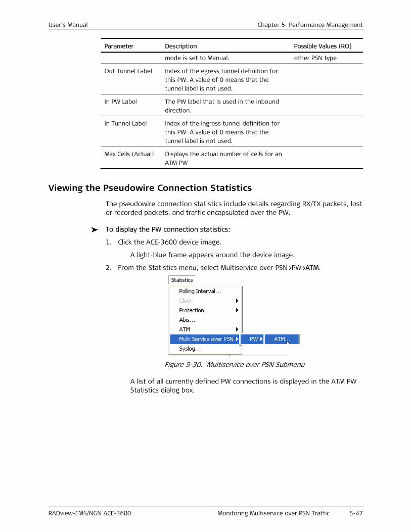
User's Manual Chapter 5 Performance Management
RADview-EMS/NGN ACE-3600 Monitoring Multiservice over PSN Traffic 5-47
Parameter Description Possible Values (RO)
mode is set to Manual. other PSN type
Out Tunnel Label Index of the egress tunnel definition for
this PW. A value of 0 means that the
tunnel label is not used.
In PW Label The PW label that is used in the inbound
direction.
In Tunnel Label Index of the ingress tunnel definition for
this PW. A value of 0 means that the
tunnel label is not used.
Max Cells (Actual) Displays the actual number of cells for an
ATM PW
Viewing the Pseudowire Connection Statistics
The pseudowire connection statistics include details regarding RX/TX packets, lost or recorded packets, and traffic encapsulated over the PW.
To display the PW connection statistics:
1. Click the ACE-3600 device image.
A light-blue frame appears around the device image.
2. From the Statistics menu, select Multiservice over PSN>PW>ATM.
Figure 5-30. Multiservice over PSN Submenu
A list of all currently defined PW connections is displayed in the ATM PW Statistics dialog box.

Chapter 5 Performance Management User's Manual
5-48 Monitoring Multiservice over PSN Traffic RADview-EMS/NGN ACE-3600
Figure 5-31. ATM PW Statistics Dialog Box
Table 5-23. ATM PW Statistics Parameters
Parameter Description Possible Values
(RO)
Current Number of
Entries
The current number of entries in the ATM PW
Statistics table.
0 – 1536
Maximum Number
of Entries
The maximum number of ATM PW entries that
can be defined.
1536
PW Number ID number of an existing PW connection. 1–1536
PW Name Name of pseudowire connection.
PW Type Type of pseudowire connection.
Defines the PW type and the type of data it
carries.
ATM VP 1 to 1
ATM VC 1 to 1
ATM VP N to 1
ATM VC N to 1
AAL5-SDU

User's Manual Chapter 5 Performance Management
RADview-EMS/NGN ACE-3600 Monitoring Multiservice over PSN Traffic 5-49
Parameter Description Possible Values
(RO)
SAToP
Basic CES PSN
PSN Type The type of packet-switched network on
which this PW is established. "o" stands for
over.
Note:
• UDPoIP is valid only for SAToP and Basic CES PSN pseudowire types.
• MPLSoIP cannot be selected when the PW subtype is clock distribution.
MPLS
UDPoIP
MPLSoIP
MPLSoGRE
Out PW Label The PW label that is used in the outbound
direction. Relevant only if the PW subtype is
clock recovery and if the provisioning mode is
set to Manual.
1–4095 if the PSN
type is UDPoIP
16–1048575 for
any other PSN type
In PW Label The PW label that is used in the inbound
direction. Not relevant for clock distribution.
If the PW is defined manually and the PSN
type is MPLS, MPLSoIP, or MPLSoGRE, the PW
value range must be within the static label
range.
1–4095 if the PSN
type is UDPoIP
16–65534 for any
other PSN type
Peer ID number and name of an existing
(previously defined) remote targeted peer.
Peer ID number: 1–
512
Displaying the Statistics from a Specific PW
To display the PW statistics from a specific PW:
1. In the ATM PW Statistics dialog box (see Figure 5-31), click <Start From>
The Start From dialog box appears.
.
Figure 5-32. Start From Dialog Box
2. In PW Number, type the number of the first PW to appear on the list, and then click <Select>.
The ATM PW Statistics dialog box displays the PWs beginning from the selected PW number.

Chapter 5 Performance Management User's Manual
5-50 Monitoring Multiservice over PSN Traffic RADview-EMS/NGN ACE-3600
Viewing the Pseudowire Current Cells Statistics
To view the current cells statistics of a specific PW:
1. In the ATM PW Statistics dialog box (see Figure 5-31), select (highlight) the PW row.
2. Select the top-left radio button corresponding to Current Cells.
3. Click <Statistics>.
The ATM PW current cells statistics are displayed in a separate dialog box.
Figure 5-33. ATM PW Current Cells Statistic
Table 5-24. ATM PW Current Cells Statistics Parameters
Parameter Description Possible Values
(RO)
PW Number ID number of an existing (previously defined)
PW connection for which the details are
displayed above. You can enter a different
PW number to view its connection status, or
1–1536

User's Manual Chapter 5 Performance Management
RADview-EMS/NGN ACE-3600 Monitoring Multiservice over PSN Traffic 5-51
Parameter Description Possible Values
(RO)
press F to view the next PW.
PW Name Name of pseudowire connection.
PW Type Type of pseudowire connection.
Defines the PW type and the type of data it
carries.
ATM VP 1 to 1
ATM VC 1 to 1
ATM VP N to 1
ATM VC N to 1
AAL5-SDU
SAToP
Basic CES PSN
PSN Type The type of packet-switched network on
which this PW is established. "o" stands for
over.
Note:
• UDPoIP is valid only for SAToP and Basic CES PSN pseudowire types.
• MPLSoIP cannot be selected when the PW subtype is clock distribution.
MPLS
UDPoIP
MPLSoIP
MPLSoGRE
Time Elapsed (sec) The period in seconds since the beginning of
the current interval.
0–899
Unknown VP/VC
Cells
Number of cells that were received from the
PSN with an unknown VPI/VCI value. Relevant
only for N:1 VC/VP PW types.
Numerical
ATM Rx cells Number of complete cells received on the
specified VC/VP from the ATM side.
Numerical
Rx Policing
Discarded Cells
CLP (0+1)
Total number of discarded cells. Numerical
--
Rx Policing
Discarded Cells
CLP (0)
Total number of discarded cells with CLP = 0. Numerical
--
Rx Tagged Cells
ATM Tx cells Number of cells transmitted on the specified
VC/VP toward the ATM side.
Numerical
To close the PW current cells statistics table:
• Click <Close>.
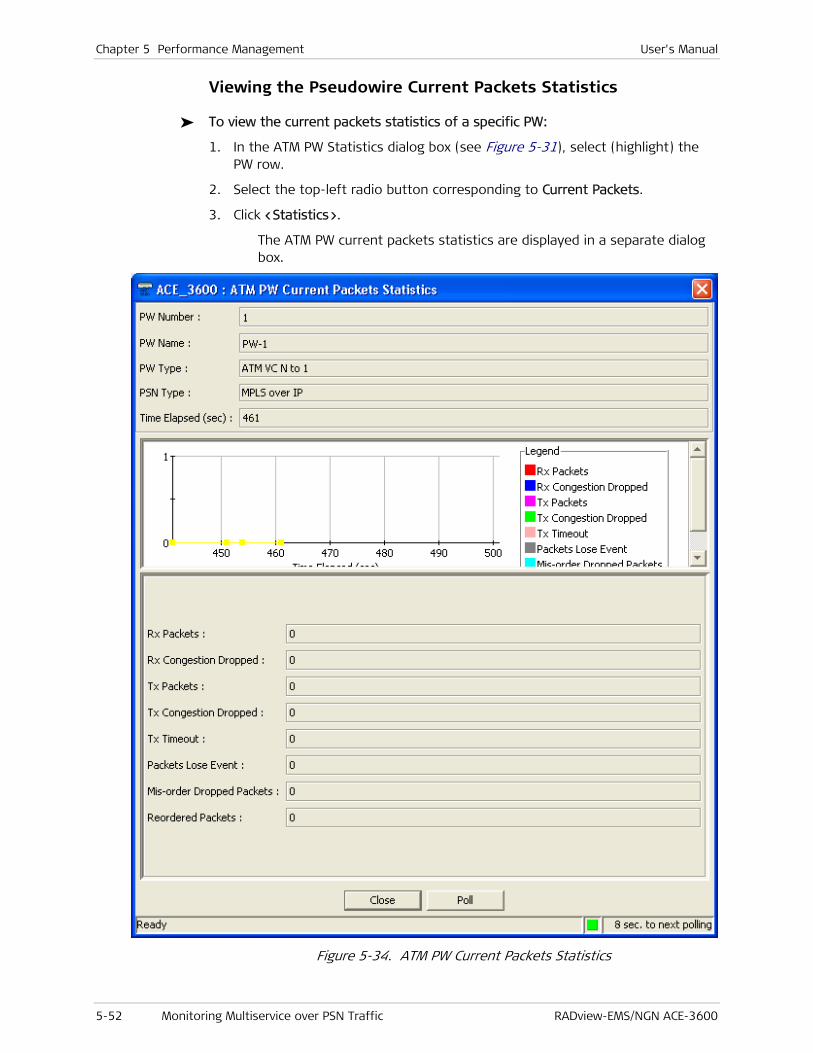
Chapter 5 Performance Management User's Manual
5-52 Monitoring Multiservice over PSN Traffic RADview-EMS/NGN ACE-3600
Viewing the Pseudowire Current Packets Statistics
To view the current packets statistics of a specific PW:
1. In the ATM PW Statistics dialog box (see Figure 5-31), select (highlight) the PW row.
2. Select the top-left radio button corresponding to Current Packets.
3. Click <Statistics>.
The ATM PW current packets statistics are displayed in a separate dialog box.
Figure 5-34. ATM PW Current Packets Statistics
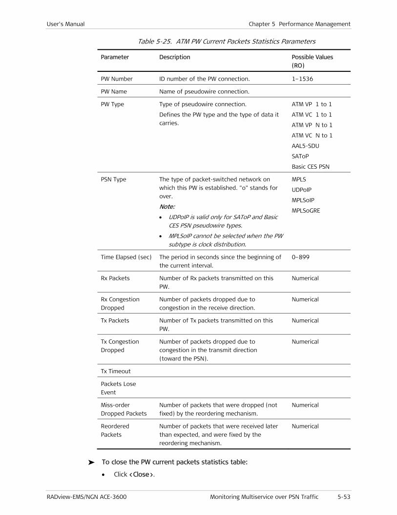
User's Manual Chapter 5 Performance Management
RADview-EMS/NGN ACE-3600 Monitoring Multiservice over PSN Traffic 5-53
Table 5-25. ATM PW Current Packets Statistics Parameters
Parameter Description Possible Values
(RO)
PW Number ID number of the PW connection. 1–1536
PW Name Name of pseudowire connection.
PW Type Type of pseudowire connection.
Defines the PW type and the type of data it
carries.
ATM VP 1 to 1
ATM VC 1 to 1
ATM VP N to 1
ATM VC N to 1
AAL5-SDU
SAToP
Basic CES PSN
PSN Type The type of packet-switched network on
which this PW is established. "o" stands for
over.
Note:
• UDPoIP is valid only for SAToP and Basic CES PSN pseudowire types.
• MPLSoIP cannot be selected when the PW subtype is clock distribution.
MPLS
UDPoIP
MPLSoIP
MPLSoGRE
Time Elapsed (sec) The period in seconds since the beginning of
the current interval.
0–899
Rx Packets Number of Rx packets transmitted on this
PW.
Numerical
Rx Congestion
Dropped
Number of packets dropped due to
congestion in the receive direction.
Numerical
Tx Packets Number of Tx packets transmitted on this
PW.
Numerical
Tx Congestion
Dropped
Number of packets dropped due to
congestion in the transmit direction
(toward the PSN).
Numerical
Tx Timeout
Packets Lose
Event
Miss-order
Dropped Packets
Number of packets that were dropped (not
fixed) by the reordering mechanism.
Numerical
Reordered
Packets
Number of packets that were received later
than expected, and were fixed by the
reordering mechanism.
Numerical
To close the PW current packets statistics table:
• Click <Close>.
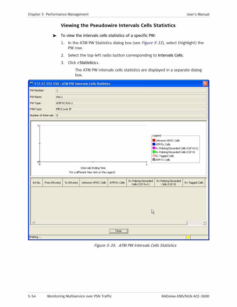
Chapter 5 Performance Management User's Manual
5-54 Monitoring Multiservice over PSN Traffic RADview-EMS/NGN ACE-3600
Viewing the Pseudowire Intervals Cells Statistics
To view the intervals cells statistics of a specific PW:
1. In the ATM PW Statistics dialog box (see Figure 5-31), select (highlight) the PW row.
2. Select the top-left radio button corresponding to Intervals Cells.
3. Click <Statistics>.
The ATM PW intervals cells statistics are displayed in a separate dialog box.
Figure 5-35. ATM PW Intervals Cells Statistics

User's Manual Chapter 5 Performance Management
RADview-EMS/NGN ACE-3600 Monitoring Multiservice over PSN Traffic 5-55
Table 5-26. ATM PW Intervals Cells Statistics Parameters
Parameter Description Possible Values
(RO)
PW Number ID number of an existing (previously defined)
PW connection for which the details are
displayed above. You can enter a different
PW number to view its connection status, or
press F to view the next PW.
1–1536
PW Name Name of pseudowire connection.
PW Type Type of pseudowire connection.
Defines the PW type and the type of data it
carries.
ATM VP 1 to 1
ATM VC 1 to 1
ATM VP N to 1
ATM VC N to 1
AAL5-SDU
SAToP
Basic CES PSN
PSN Type The type of packet-switched network on
which this PW is established. "o" stands for
over.
Note:
• UDPoIP is valid only for SAToP and Basic CES PSN pseudowire types.
• MPLSoIP cannot be selected when the PW subtype is clock distribution.
MPLS
UDPoIP
MPLSoIP
MPLSoGRE
Number of
Intervals
The number of intervals that are saved. 0–24
Int No. Number of the displayed interval. 0–24, or 0 to last
existing interval
From (hh:mm) The time that the interval started. 00:00 to 23:59
To (hh:mm) The time that the interval ended. 00:00 to 23:59
Unknown VP/VC
Cells
Number of cells that were received from the
PSN with an unknown VPI/VCI value. Relevant
only for N:1 VC/VP PW types.
Numerical
ATM Rx cells Number of complete cells received on the
specified VC/VP from the ATM side.
Numerical
Rx Policing
Discarded Cells
CLP (0+1)
Total number of discarded cells. 0 to 2^32-1
--
Rx Policing
Discarded Cells
CLP (0)
Total number of discarded cells with CLP = 0. 0 to 2^32-1
--
Rx Tagged Cells

Chapter 5 Performance Management User's Manual
5-56 Monitoring Multiservice over PSN Traffic RADview-EMS/NGN ACE-3600
Parameter Description Possible Values
(RO)
ATM Tx Cells Number of cells transmitted on the specified
VC/VP toward the ATM side.
Numerical
To close the PW intervals cells statistics table:
• Click <Close>.
Viewing the Pseudowire Intervals Packets Statistics
To view the intervals packets statistics of a specific PW:
1. In the ATM PW Statistics dialog box (see Figure 5-31), select (highlight) the PW row.
2. Select the top-left radio button corresponding to Packets Cells.
3. Click <Statistics>.
The ATM PW intervals packets statistics are displayed in a separate dialog box.

User's Manual Chapter 5 Performance Management
RADview-EMS/NGN ACE-3600 Monitoring Multiservice over PSN Traffic 5-57
Figure 5-36. ATM PW Intervals Packets Statistics
Table 5-27. ATM PW Intervals Packets Statistics Parameters
Parameter Description Possible Values
PW Number ID number of the PW connection. 1–1536
PW Name Name of pseudowire connection.
Type Type of pseudowire connection.
Defines the PW type and the type of data it
carries.
ATM VP 1 to 1
ATM VC 1 to 1
ATM VP N to 1
ATM VC N to 1
AAL5-SDU
SAToP
Basic CES PSN
PSN Type The type of packet-switched network on
which this PW is established. "o" stands for
over.
MPLS
UDPoIP

Chapter 5 Performance Management User's Manual
5-58 Monitoring Multiservice over PSN Traffic RADview-EMS/NGN ACE-3600
Parameter Description Possible Values
Note:
• UDPoIP is valid only for SAToP and Basic CES PSN pseudowire types.
• MPLSoIP cannot be selected when the PW subtype is clock distribution.
MPLSoIP
MPLSoGRE
Number of
Intervals
The number of intervals that are saved. 0–24
Int. No. Number of the displayed interval.
You can enter a different number of press
^F to view the next interval.
0–24, or 0 to last
existing interval
From (hh:mm) The interval start time. 00:00 to 23:59
To (hh:mm) The interval end time. 00:00 to 23:59
Rx Packets Number of packets received on this PW. Numerical
Rx Congestion
Dropped
Number of packets dropped due to
congestion in the receive direction.
Numerical
Tx Packets Number of packets transmitted on this PW. Numerical
Tx Congestion
Dropped
Number of packets dropped due to
congestion in the transmit direction
(toward the PSN).
Numerical
Tx Timeout Number of packets transmitted to the
Ethernet port due to timeout expiration.
Numerical
Packets Lose
Event
Number of losses of frame(s), which was
identified by a gap in the sequence number
and not classified as a miss-order.
Numerical
Miss-order
Dropped Packets
Number of packets that were dropped (not
fixed) by the reordering mechanism.
Numerical
Reordered
Packets
Number of packets that were received later
than expected, and were fixed by the
reordering mechanism.
Numerical
To close the PW intervals packet statistics table:
• Click <Close>.
Closing the PW Statistics Table
To close the PW statistics table:
• In the ATM PW Statistics dialog box (see Figure 5-31), click <Close>.
The ATM PW Statistics dialog box closes.

User's Manual Chapter 5 Performance Management
RADview-EMS/NGN ACE-3600 Monitoring Multiservice over PSN Traffic 5-59
Refreshing the PW Statistics Table
To update the PW statistics table with current data:
• In the ATM PW Statistics dialog box (see Figure 5-31), click <Refresh>.
The ATM PW statistics table is updated.
Viewing all Attachment Circuits
To view all ATM attachment circuits:
• From the Configuration menus, select Multiservice over PSN>View All Attachment Circuits>ATM.
The table of ATM attachment circuits is displayed.
Figure 5-37. View all ATM Attachment Circuits Dialog Box
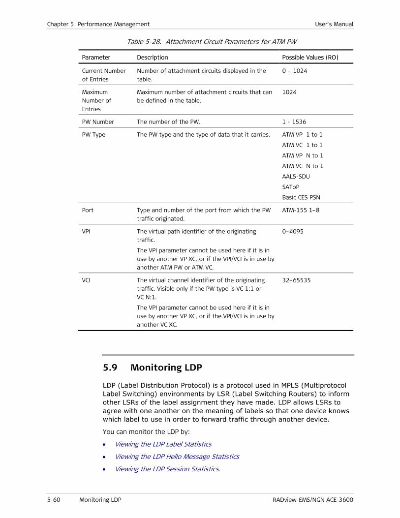
Chapter 5 Performance Management User's Manual
5-60 Monitoring LDP RADview-EMS/NGN ACE-3600
Table 5-28. Attachment Circuit Parameters for ATM PW
Parameter Description Possible Values (RO)
Current Number
of Entries
Number of attachment circuits displayed in the
table.
0 – 1024
Maximum
Number of
Entries
Maximum number of attachment circuits that can
be defined in the table.
1024
PW Number The number of the PW. 1 - 1536
PW Type
The PW type and the type of data that it carries.
ATM VP 1 to 1
ATM VC 1 to 1
ATM VP N to 1
ATM VC N to 1
AAL5-SDU
SAToP
Basic CES PSN
Port Type and number of the port from which the PW
traffic originated.
ATM-155 1–8
VPI The virtual path identifier of the originating
traffic.
The VPI parameter cannot be used here if it is in
use by another VP XC, or if the VPI/VCI is in use by
another ATM PW or ATM VC.
0–4095
VCI The virtual channel identifier of the originating
traffic. Visible only if the PW type is VC 1:1 or
VC N:1.
The VPI parameter cannot be used here if it is in
use by another VP XC, or if the VPI/VCI is in use by
another VC XC.
32–65535
5.9 Monitoring LDP
LDP (Label Distribution Protocol) is a protocol used in MPLS (Multiprotocol Label Switching) environments by LSR (Label Switching Routers) to inform other LSRs of the label assignment they have made. LDP allows LSRs to agree with one another on the meaning of labels so that one device knows which label to use in order to forward traffic through another device.
You can monitor the LDP by:
• Viewing the LDP Label Statistics
• Viewing the LDP Hello Message Statistics
• Viewing the LDP Session Statistics.

User's Manual Chapter 5 Performance Management
RADview-EMS/NGN ACE-3600 Monitoring LDP 5-61
Viewing the LDP Label Statistics
To view the LDP labels:
• From the Configuration menu, select MPLS>LDP>Labels.
The LDP Labels Table dialog box is displayed.
Figure 5-38. LDP Labels Table Dialog Box
Table 5-29. LDP Labels Table Parameters
Parameter Description Possible Values (RO)
LDP ID The LDP identifier to be used in all LDP
sessions established with the unit.
Note:
• The LDP ID must be identical to one of the interface IP addresses or system addresses.
• The LDP ID cannot be changed when LDP is enabled.
• If the LDP ID is not yet configured and a
IP address format
0.0.0.0 –
255.255.255.255
Default: 0.0.0.0

Chapter 5 Performance Management User's Manual
5-62 Monitoring LDP RADview-EMS/NGN ACE-3600
Parameter Description Possible Values (RO)
system address is defined, the system address is automatically displayed by default, and you only need to save this setting (press S).
Entity Index
Peer LDP ID The LDP ID of the peer.
See description of LDP ID in this table.
IP address format
0.0.0.0 –
255.255.255.255
Default: 0.0.0.0
Viewing the Statistics of a Single Label
To view the statistics of a single label:
• In the LDP Labels Table dialog box, select a label, and then click <Show Labels>.
The LDP Labels dialog box is displayed.
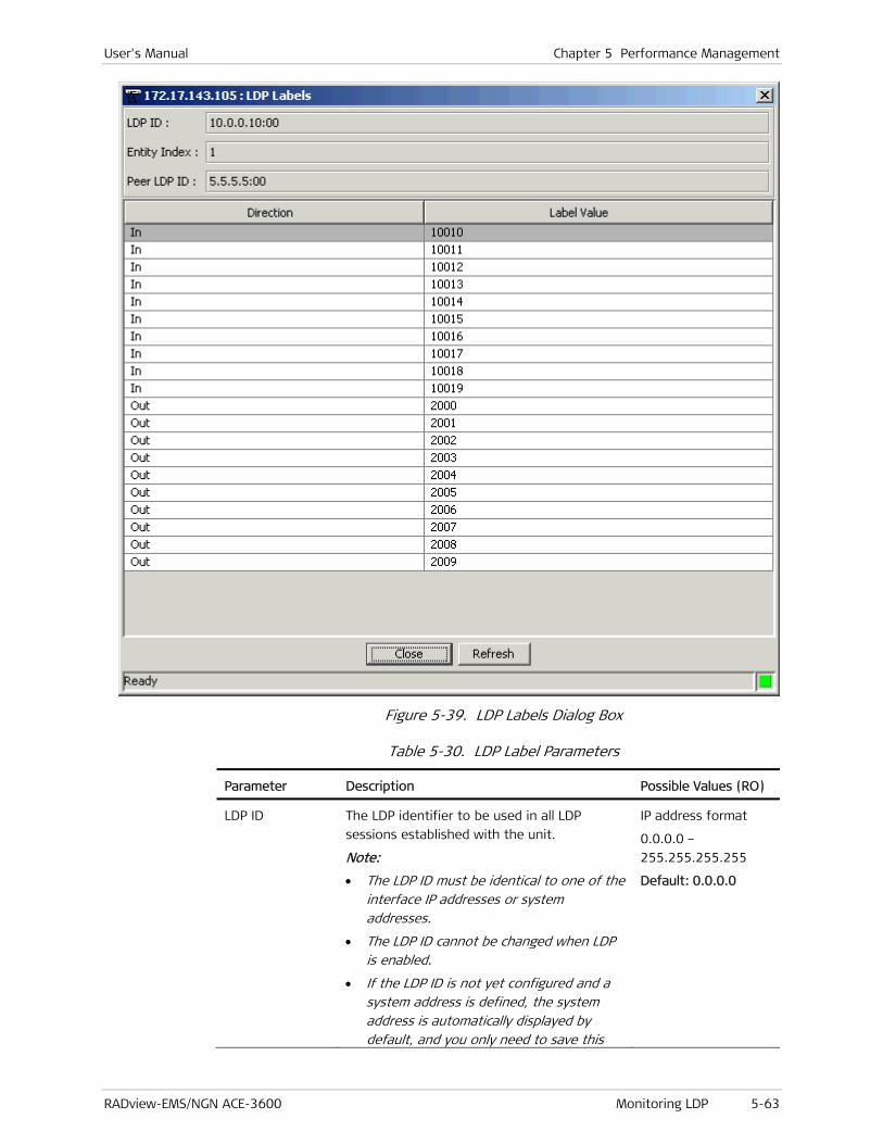
User's Manual Chapter 5 Performance Management
RADview-EMS/NGN ACE-3600 Monitoring LDP 5-63
Figure 5-39. LDP Labels Dialog Box
Table 5-30. LDP Label Parameters
Parameter Description Possible Values (RO)
LDP ID The LDP identifier to be used in all LDP
sessions established with the unit.
Note:
• The LDP ID must be identical to one of the interface IP addresses or system addresses.
• The LDP ID cannot be changed when LDP is enabled.
• If the LDP ID is not yet configured and a system address is defined, the system address is automatically displayed by default, and you only need to save this
IP address format
0.0.0.0 –
255.255.255.255
Default: 0.0.0.0

Chapter 5 Performance Management User's Manual
5-64 Monitoring LDP RADview-EMS/NGN ACE-3600
Parameter Description Possible Values (RO)
setting (press S).
Entity Index
Peer LDP ID The LDP ID of the peer.
See description of LDP ID in this table.
IP address format
0.0.0.0 –
255.255.255.255
Default: 0.0.0.0
Direction Direction of the label. In
Out
Label Value Value of the label. Numeric
Viewing the LDP Hello Message Statistics
LDP Hello messages enable LDP nodes to discover one another and to detect the failure of a neighbor or the failure of a link to a neighbor. Hello messages are sent periodically on all interfaces where LDP is enabled.
To view the LDP Hello message statistics:
• From the Configuration menu, select MPLS>LDP>Hello.
The LDP Hello Table dialog box is displayed.

User's Manual Chapter 5 Performance Management
RADview-EMS/NGN ACE-3600 Monitoring LDP 5-65
Figure 5-40. LDP Hello Table Dialog Box
Table 5-31. LDP Hello Table Parameters
Parameter Description Possible Values (RO)
LDP ID LDP ID of the local unit. IP address format
0.0.0.0 –
255.255.255.255
Peer LDP ID LDP ID of the remote peer. IP address format
0.0.0.0 –
255.255.255.255
Type The type of Hello adjacency:
• Link – The adjacencies are established
with basic discovery.
• Targeted – The adjacencies are
established with extended discovery.
Link
Targeted
Interval (sec) The frequentness of sending Hello
messages by the local unit

Chapter 5 Performance Management User's Manual
5-66 Monitoring LDP RADview-EMS/NGN ACE-3600
Parameter Description Possible Values (RO)
Time left (sec) The time in seconds during which the local
unit waits for the peer to send a Hello
message
Viewing the LDP Session Statistics
To view the LDP session statistics:
• From the Configuration menu, select MPLS>LDP>Sessions.
The LDP Sessions Table dialog box is displayed.
Figure 5-41. LDP Sessions Table Dialog Box
Table 5-32. LDP Sessions Statistics Parameters
Parameter Description Possible Values (RO)
LDP ID LDP ID of the local unit.
Peer LDP ID LDP ID of the remote peer.
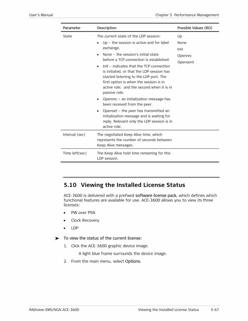
User's Manual Chapter 5 Performance Management
RADview-EMS/NGN ACE-3600 Viewing the Installed License Status 5-67
Parameter Description Possible Values (RO)
State The current state of the LDP session:
• Up – the session is active and for label
exchange.
• None – the session's initial state
before a TCP connection is established.
• Init – indicates that the TCP connection
is initiated, or that the LDP session has
started listening to the LDP port. The
first option is when the session is in
active role, and the second when it is in
passive role.
• Openrec – an initialization message has
been received from the peer.
• Openset – the peer has transmitted an
initialization message and is waiting for
reply. Relevant only the LDP session is in
active role.
Up
None
Init
Openrec
Opensent
Interval (sec) The negotiated Keep Alive time, which
represents the number of seconds between
Keep Alive messages.
Time left(sec) The Keep Alive hold time remaining for this
LDP session.
5.10 Viewing the Installed License Status
ACE-3600 is delivered with a prefixed software license pack, which defines which functional features are available for use. ACE-3600 allows you to view its three licenses:
• PW over PSN
• Clock Recovery
• LDP
To view the status of the current license:
1. Click the ACE-3600 graphic device image.
A light blue frame surrounds the device image.
2. From the main menu, select Options.

Chapter 5 Performance Management User's Manual
5-68 Viewing the Installed License Status RADview-EMS/NGN ACE-3600
Figure 5-42. Options Menu
3. From the Options menu, select License Status.
The License Status dialog box is displayed.
Figure 5-43. License Status Dialog Box
Table 5-33. License Status Parameters
Parameter Description Possible Values (RO)
PW over PSN A license that when enabled, provides all
the multiservice over PSN capabilities of
the ACE-3600.
Installed
Not Installed
Clock Recovery A license that when enabled, provides all
the adaptive clock recovery capabilities
over PSN.
Installed
Not Installed
LDP A license that when enabled, provides
LDP signaling capabilities for PW
establishment.
Installed
Not Installed

User's Manual Chapter 5 Performance Management
RADview-EMS/NGN ACE-3600 Viewing the Syslog Statistics 5-69
5.11 Viewing the Syslog Statistics
If ACE-3600 was set to log events on a Syslog server, you can display the statistics of these events.
To display the Syslog statistics:
• From the Statistics menu, select Syslog.
The Syslog Statistics dialog box is displayed.
Figure 5-44. Syslog Statistics Dialog Box
Table 5-34. Syslog Statistics Parameters
Parameter Description Possible Values
Total TX
Messages
Number of messages transmitted by the
Syslog server.
Numerical integer
Unqueued
Dropped
Messages
Number of messages that could not be
queued for transmission by the Syslog
server.
Numerical integer
To poll the Syslog statistics:
• In the Syslog Statistics dialog box (see Figure 5-44), click <Poll>.
To close the Syslog statistics:
• In the Syslog Statistics dialog box (see Figure 5-44), click <Close>.
The Syslog Statistics dialog box closes.

Chapter 5 Performance Management User's Manual
5-70 Viewing the Syslog Statistics RADview-EMS/NGN ACE-3600

RADview-EMS/NGN ACE-3600 Changing Usernames 6-1
Chapter 6
Security Management RADview-EMS/NGN ACE-3600 provides for secure access at the menu, dialog box, and function (add, change, delete, and view) levels.
Security management includes:
• Adding Users
• Changing Usernames
• Changing Passwords
• Setting Management Access Authorization
• Enabling SNMPv3.
6.1 Adding Users
Part of security management is creating and adding users in the system. Each user has to have a username and a password to be identified when logging in. Each user is normally assigned a set of permissions, as follows:
• Administrator – Unlimited access to all operations including User Administration.
• Operator – Full write mode and access to all operations, except for User/System Administration (read only).
• Technician – Limited access to configuration operations, and read-only mode for Event Browser.
• Monitor – Read-only mode for configuration operations, and no access to other applications.
For details about how to add users, see the RADview-EMS/NGN (PC/Unix) system manual.
6.2 Changing Usernames
A unique username identifies the user when accessing a multi-user system. A username is assigned to the user and can later be changed.
For details on how to change a username, see the RADview-EMS/NGN (PC/Unix) system manual.
Chapter 6 Security Management User's Manual
6-2 Setting Management Access Authorization RADview-EMS/NGN ACE-3600
6.3 Changing Passwords
You require a password together with a corresponding username, in order to gain access to the system. You can personalize and change your login password to easily remember it. In order to change to a new password, you must enter the old password, for verification purposes. Only letters and numbers are valid password characters.
For details on how to change passwords in RADview-EMS/NGN ACE-3600, see the RADview-EMS/NGN (PC/Unix) system manual.
6.4 Setting Management Access Authorization
This section includes information on:
• Using the EMS Security Console
• Setting a Security Profile
• Setting Permissions.
Using the EMS Security Console
The EMS Admin Console hosts the EMS administration tools, which are called consoles. The EMS Security Console is a tool that enables users with security administrative rights to do the following:
• View and manage the EMS Security profiles in a graphical interface.
• Create and edit security profiles.
• Manage user accounts.
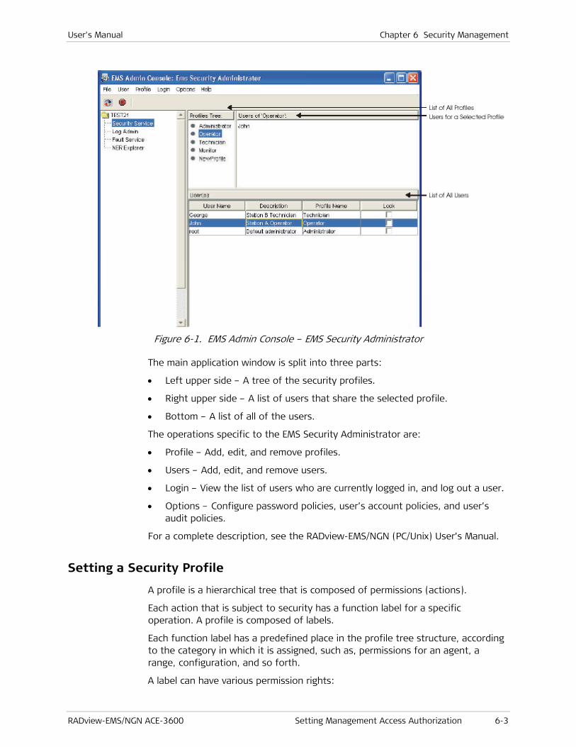
User's Manual Chapter 6 Security Management
RADview-EMS/NGN ACE-3600 Setting Management Access Authorization 6-3
Figure 6-1. EMS Admin Console – EMS Security Administrator
The main application window is split into three parts:
• Left upper side – A tree of the security profiles.
• Right upper side – A list of users that share the selected profile.
• Bottom – A list of all of the users.
The operations specific to the EMS Security Administrator are:
• Profile – Add, edit, and remove profiles.
• Users – Add, edit, and remove users.
• Login – View the list of users who are currently logged in, and log out a user.
• Options – Configure password policies, user’s account policies, and user’s audit policies.
For a complete description, see the RADview-EMS/NGN (PC/Unix) User’s Manual.
Setting a Security Profile
A profile is a hierarchical tree that is composed of permissions (actions).
Each action that is subject to security has a function label for a specific operation. A profile is composed of labels.
Each function label has a predefined place in the profile tree structure, according to the category in which it is assigned, such as, permissions for an agent, a range, configuration, and so forth.
A label can have various permission rights:

Chapter 6 Security Management User's Manual
6-4 Setting Management Access Authorization RADview-EMS/NGN ACE-3600
• Write (which includes Read)
• Read
• Not Available
Setting Permissions
Figure 6-2 shows the available permissions on the right pane and the individual permissions that have been assigned to a profile on the left pane.
The types of profiles are:
• Mandatory – Administrator, Operator, Technician, and Monitor.
Mandatory profiles cannot be edited or deleted.
• User-defined – Created from scratch or derived from an existing profile.
A user is assigned only one role (profile). However, a role (profile) can be assigned to many users.
Figure 6-2. Permission Hierarchy
The hierarchical permission tree shows:
• Available permissions that have been loaded (on the right pane).
• Group permissions.
• Individual permissions that have been assigned (and can be modified) for the new profile (on the left pane).
Note
User's Manual Chapter 6 Security Management
RADview-EMS/NGN ACE-3600 Enabling SNMPv3 6-5
• Permissions that have been modified for a range of IP addresses (on the left pane).
• Permissions that have been modified for a specific slot or port instance (on the left pane).
6.5 Enabling SNMPv3
ACE-3600 supports SNMP version 3, providing secure access to the device by authenticating and encrypting packets transmitted over the network.
Enabling SNMPv3 is recommended for greater management access and security.
For a detailed explanation on enabling the SNMPv3, refer to the RADview-EMS/NGN system manual, or to the ACE-3600 Installation and Operation Manual (hardware manual).

Chapter 6 Security Management User's Manual
6-6 Enabling SNMPv3 RADview-EMS/NGN ACE-3600
RADview-EMS/NGN ACE-3600 Monitoring Object Status 7-1
Chapter 7
Fault Management This chapter describes the following RADview ACE-3600 fault management options:
• Monitoring Object Status
• Performing Diagnostic Tests
• Troubleshooting
• Frequently Asked Questions
• Technical Support.
7.1 Monitoring Object Status
The object status monitoring includes the following:
• Interpreting the Map Icon Colors
• Viewing the Active Alarms
• Viewing the History Log
• Clearing the History Log.
Interpreting the Map Icon Colors
The color of the ACE-3600 icon on the SNMPc map is based on polling and SNMP events, and indicates the following:
• Green icon – The SNMP connectivity between the Agent and the NMS is good.
• Red icon – A timeout or a failed interaction with the agent occurred.
• Magenta icon – Traps were received.
• Yellow frame – A minor alarm is present.
• Green frame – Alarms are not present.
• Red frame – A major alarm is present.
• Dark blue frame – A warning alarm is present.
• Orange frame – A major alarm is present.
The color of the ACE-3600 icon on the HPOV map is based on polling and SNMP events, as followsis:
• Yellow – A minor alarm is present.

Chapter 7 Fault Management User's Manual
7-2 Monitoring Object Status RADview-EMS/NGN ACE-3600
• Green – Alarms are not present.
• Red – A timeout or a failed interaction with the agent occurred.
• Cyan – A warning alarm is present.
• Orange – A major alarm is present.
Viewing the Active Alarms
The Active Alarms information indicates any current alarm that requires your attention.
To view the active alarms:
1. Click the ACE-3600 graphic device image.
A light blue frame surrounds the device image.
2. From the Fault menu, select All Active Alarms.
Figure 7-1. System Level Fault Menu
The All Active Alarm List dialog box appears.
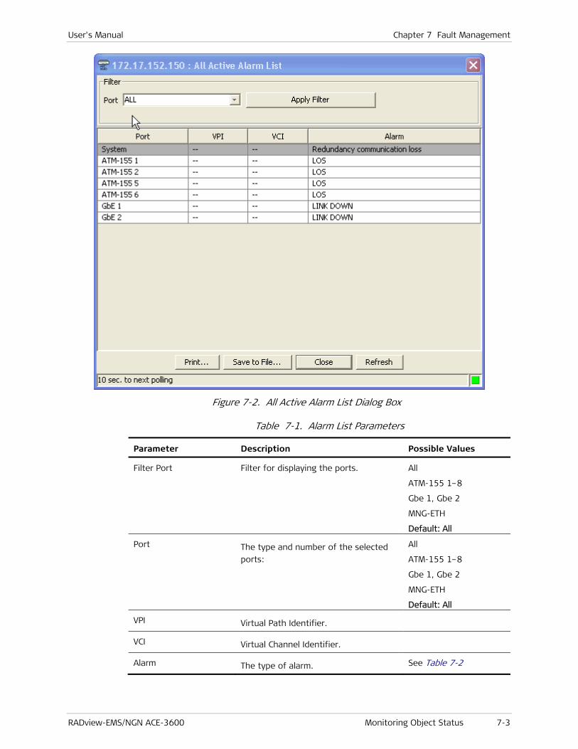
User's Manual Chapter 7 Fault Management
RADview-EMS/NGN ACE-3600 Monitoring Object Status 7-3
Figure 7-2. All Active Alarm List Dialog Box
Table 7-1. Alarm List Parameters
Parameter Description Possible Values
Filter Port Filter for displaying the ports. All
ATM-155 1–8
Gbe 1, Gbe 2
MNG-ETH
Default: All
Port The type and number of the selected
ports:
All
ATM-155 1–8
Gbe 1, Gbe 2
MNG-ETH
Default: All
VPI Virtual Path Identifier.
VCI Virtual Channel Identifier.
Alarm The type of alarm. See Table 7-2

Chapter 7 Fault Management User's Manual
7-4 Monitoring Object Status RADview-EMS/NGN ACE-3600
Table 7-2. Alarm Types
Type of Alarm Description Possible Values
System alarm System-level alarms. Currently there is no
alarm indication at the
system level.
ETH alarm Alarm indication for ETH1 and ETH2.
The operating or administrative
status of the ETH link is down.
Link Down
ATM-155 physical alarm
Physical alarm indication for all the
device ports.
STM-1:
LOS, LOF, Line AIS, Line
RDI, and Line FEBE.
STM-1 only:
LOP, Path AIS, SLM, LCD,
Path RDI, Section BIP,
Line BIP, Path BIP, and
Path FEBE.
VP alarm Virtual Path Alarms.
VP AIS, VP LOSS of
Continuity, VP RDI
Reception, and VP
Loopback Failure.
Port alarm
Type and number of
active port
ATM-155 1–8
VPI Alarm Virtual Path Identifier.
When irrelevant, the value in this field
is ‘—’.
0–255
VCI Alarm Virtual Channel Identifier.
When irrelevant, the value in this field
is ‘—’.
32–65535
VC Alarm VC AIS, VC LOSS of
Continuity, VC RDI
Reception, and VC
Loopback Failure.
Filtering the All Active Alarm List
You can filter the All Active Alarm list to display relevant alarms according to a specific filter configuration.
To display alarms for a specific port:
• In the All Active Alarm List dialog box (see Figure 7-2), select the required port, and then click <Apply Filter>.
User's Manual Chapter 7 Fault Management
RADview-EMS/NGN ACE-3600 Monitoring Object Status 7-5
The All Active Alarm list displays only those alarms that are relevant to the selected port.
Printing the All Active Alarm List
To print the All Active Alarm list:
1. In the All Active Alarm List dialog box (see Figure 7-2), click <Print>.
The Print dialog box appears.
2. In the Print dialog box, select the required print features, and then click <OK>.
The All Active Alarm list is printed.
Saving the All Active Alarm List
You can save the All Active Alarm List in a file.
To save the All Active Alarm list:
1. In the All Active Alarm List dialog box (see Figure 7-2), click <Save to File>.
The Save dialog box appears.
2. In the Save dialog box, specify the destination name and directory, and then click <Save>.
The All Active Alarm list is saved.
Closing the All Active Alarm List
To close the All Active Alarm list:
• In the All Active Alarm List dialog box (see Figure 7-2), click <Close>.
The All Active Alarm list dialog box closes.
Refreshing the All Active Alarm List
To update the All Active Alarm list with current data:
• In the All Active Alarm List dialog box (see Figure 7-2), click <Refresh>.
The All Active Alarm list is updated.
Viewing the History Log
The history log records the details of all system events. The System Log Buffer dialog box displays 100 log entries per page, and the buffer itself can hold up to 2048 log entries.
Setting the ACE-3600 device to its default configuration does not affect the history log. The history log entries are kept even after a device reset operation, and can only be deleted manually.
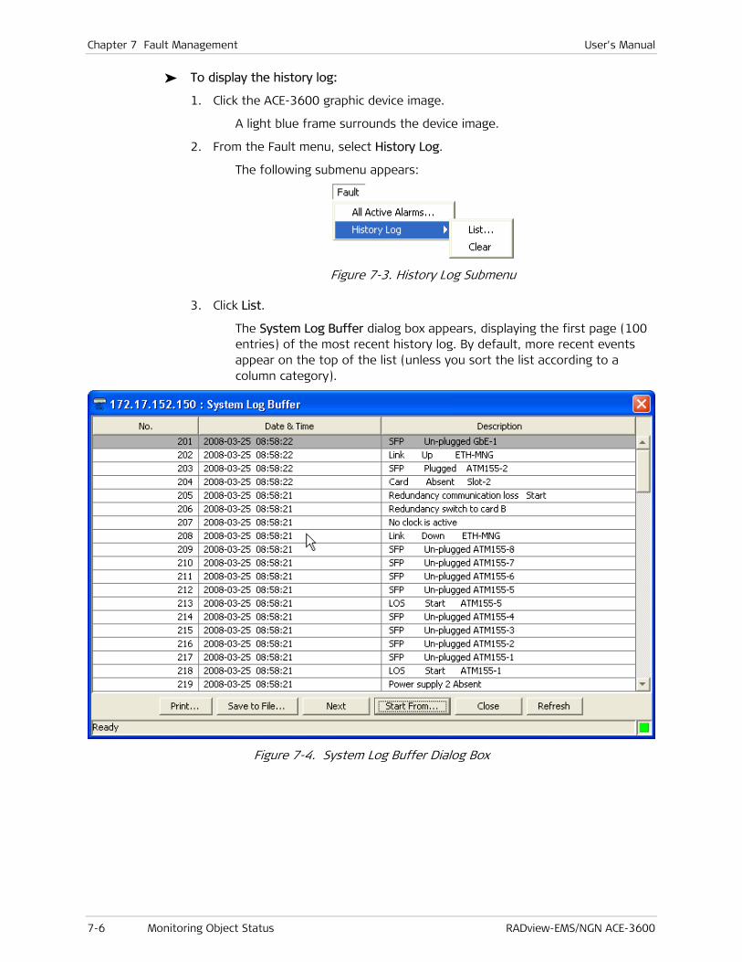
Chapter 7 Fault Management User's Manual
7-6 Monitoring Object Status RADview-EMS/NGN ACE-3600
To display the history log:
1. Click the ACE-3600 graphic device image.
A light blue frame surrounds the device image.
2. From the Fault menu, select History Log.
The following submenu appears:
Figure 7-3. History Log Submenu
3. Click List.
The System Log Buffer dialog box appears, displaying the first page (100 entries) of the most recent history log. By default, more recent events appear on the top of the list (unless you sort the list according to a column category).
Figure 7-4. System Log Buffer Dialog Box

User's Manual Chapter 7 Fault Management
RADview-EMS/NGN ACE-3600 Monitoring Object Status 7-7
The displayed Date & Time of each log entry is of the Agent date and time. If the NMS station and the Agent clock are not synchronized, events in the log file may have a certain date and time, while the same event in the interval statistics is displayed under the local station’s date and time.
Therefore, it is recommended to synchronize the NMS clock with the Agent clock using the Net Date & Time shell application (for more information, refer to the RADview-EMS/NGN system manual).
Table 7-3. System Log Buffer Parameters
Parameter Description Possible Values
No. Sequential number of each log entry. The most
recent entry is 1.
The log buffer can hold up to 2048 entries. When
the log buffer is full and a new event is recorded,
the oldest event is dropped.
1–2048
Date & Time The date and time that the event was received,
where date is in the format YYY-MM-DD and time
is in the format HH-MM-SS.
2000-01-01 00-00-
00 to 2099-12-31
23-59-59
Description The description of the received event
Printing the History Log
To print the history log:
1. In the System Log Buffer dialog box (see Figure 7-4), click <Print>.
The Print dialog box appears.
2. In the Print dialog box, select the required print features, and then click <OK>.
The history log is printed.
Saving the History Log
You can save the history log in a file.
To save the history log:
1. In the System Log Buffer dialog box (see Figure 7-4), click <Save to File>.
The Save dialog box appears.
2. In the Save dialog box, specify the destination name and directory, and then click <Save>.
The history log is saved.
Note

Chapter 7 Fault Management User's Manual
7-8 Monitoring Object Status RADview-EMS/NGN ACE-3600
Viewing the Next Page of the History Log
To display the next page of the history log:
• In the System Log Buffer dialog box (see Figure 7-4), click <Next>.
The next page of 100 entries is displayed.
The <Next> button is disabled after NMS has displayed the last page.
Viewing the History Log from a Specific Entry
To display the history log beginning at a specific entry:
1. In the System Log Buffer dialog box (see Figure 7-4), click <Start From>.
The Start From dialog box opens.
Figure 7-5. Start From Dialog Box
2. In No., type the required log entry number, and then click <Select>.
The history log is displayed beginning at the selected entry.
You can click the <Next> button to display the next entries.
Closing the History Log
To close the history log:
• In the System Log Buffer dialog box (see Figure 7-4), click <Close>.
The System Log Buffer dialog box closes.
Refreshing the History Log
To update the history log with current data:
• In the System Log Buffer dialog box (see Figure 7-4), click <Refresh>.
The history log display is updated.
Clearing the History Log
To clear the history log:
1. From the History Log submenu (see Figure 7-3), select Clear.
Note
Note

User's Manual Chapter 7 Fault Management
RADview-EMS/NGN ACE-3600 Performing Diagnostic Tests 7-9
A confirmation dialog box appears.
Figure 7-6. History Log Clear Confirmation Dialog Box
2. Click <OK> to clear all the entries from the log buffer.
Once deleted, log entries cannot be restored. It is therefore recommended to save the current history log to a file (using <Save to File> in the System Log Buffer dialog box) prior to the deletion. Clicking <Cancel> on the confirmation message cancels the deletion.
7.2 Performing Diagnostic Tests
You can perform various diagnostic tests, as described in the following sections:
• Viewing the Self Test Results
• Setting the Loopback Timeout
• Viewing and Performing Diagnostics on an ATM-155 Port
• Performing a Cell Test.
The system level diagnostic features include the options to suspend loopbacks for a defined period, and to perform cell transmission tests.
Viewing the Self Test Results
ACE-3600 performs a self test upon power-up, and its results can be displayed in the Self Test Results dialog box.
To access the Self Test Results screen:
1. Click the ACE-3600 graphic device image.
A light blue frame surrounds the device image.
2. On the main menu, click Diagnostics.
The Diagnostics menu appears.
Note

Chapter 7 Fault Management User's Manual
7-10 Performing Diagnostic Tests RADview-EMS/NGN ACE-3600
Figure 7-7. System Level Diagnostics Menu
3. From the Diagnostics menu, select Self Test Results.
The self test results are displayed.
Figure 7-8. Self Test Results Dialog Box
Table 7-4. Self Test Results Parameters
Parameter Description Possible Values (R/O)
Module The system module that underwent a self test.
Result The result of the self test:
• "Passed" - The test has passed successfully (no
error/malfunction has been found).
Passed
Failed

User's Manual Chapter 7 Fault Management
RADview-EMS/NGN ACE-3600 Performing Diagnostic Tests 7-11
Parameter Description Possible Values (R/O)
• "Failed" - The test has failed (an
error/malfunction has been found).
To close the Self Test Results dialog box:
• In the Self Test Results dialog box (see Figure 7-8), click <Close>.
The Self Test Results dialog box closes.
To update the self test results with current data:
• In the Self Test Results dialog box (see Figure 7-8), click <Refresh>.
The self test results display is updated.
Setting the Loopback Timeout
The system level diagnostic features include the option to suspend loopbacks for a defined period.
A loopback test is a diagnostic procedure during which a signal is transmitted towards the network and then returned to the initiating device.
The objective of the loopback test is to determine whether the initiating device has any internal faults, or to identify a failing node in a network.
This Loopback menu entry is available even when there is no communication with the Agent. If the test causes a disconnection, you can terminate it at any time.
To set the loopback operation timeout:
1. Click the ACE-3600 graphic device image.
A light blue frame surrounds the device image.
2. On the main menu, click Diagnostics.
The Diagnostics menu appears (see Figure 7-7).
3. From the Diagnostics menu, select Loopback Timeout.
The Loopback Timeout dialog box appears.
Figure 7-9. Loopback Timeout Dialog Box
4. In Loopback Timeout, type the required minutes value (see Table 7-5), and then click <Set>.

Chapter 7 Fault Management User's Manual
7-12 Performing Diagnostic Tests RADview-EMS/NGN ACE-3600
RADview validates the entered value and sets the timeout as defined.
If the entered timeout value is not within the acceptable range, an error message is displayed and the previous value is kept.
Table 7-5. Loopback Timeout Parameters
Parameter Description Possible Values (RW)
Loopback Timeout
(min.)
Typer the number of minutes after which
the loopback should be disabled.
The loopback timeout is applicable for
both external and internal loops.
0–300
Default: 5
Viewing and Performing Diagnostics on an ATM-155 Port
To perform a loopback diagnostics test:
1. In the ACE-3600 graphic device image, double-click an ATM-155 port.
The ATM-155 Port dialog box appears.
Figure 7-10. ATM-155 Port Dialog Box
2. In the port’s graphic image dialog box, select the physical layer rectangle (SONET/SDH).
A light blue frame surrounds the physical layer, and the Diagnostics menu becomes enabled.
3. From the Diagnostics menu, select Loopback.
Figure 7-11. Diagnostics Menu
Note

User's Manual Chapter 7 Fault Management
RADview-EMS/NGN ACE-3600 Performing Diagnostic Tests 7-13
The Port Loopback State dialog box appears.
Figure 7-12. Port Loopback State Dialog Box
4. In New Loopback, select the required loopback state (see Table 7-6), and then click <Set>.
The system returns to the ATM-155 Port dialog box.
Table 7-6. Port Loopback State Parameters
Parameter Description Possible Values (RO/RW)
Port Type and number of the diagnosed port. ATM-155 1–8
(Read Only)
Type The port’s operating mode SDH
(Read Only)
Current Loopback Indicates the currently running state of the
loopback test:
• Disabled – The loopback mode is
disabled.
• Internal – Sometimes referred to as local
loop. All transmitted data is also looped
back toward the receive port.
• External – Sometimes referred as remote
or line loop. The received data and clock
are also looped back toward the transmit
port.
Disabled
Internal
External
(Read Only)
New Loopback Select the required loopback mode.
This field does not appear if APS is active.
Disabled
Internal
External
(Read/Write)

Chapter 7 Fault Management User's Manual
7-14 Performing Diagnostic Tests RADview-EMS/NGN ACE-3600
While the loopback is being performed on the Agent:
• The Agent does not respond to Get requests.
• In the case of External Loopback, the Agent responds to Set requests. Therefore, you can open this dialog box (even if the Agent is disconnected from the NMS) and stop or change the loopback state.
• In the case of Internal Loopback, the Agent is disconnected from the NMS. Therefore, you have to wait until the current loopback ends.
Performing a Cell Test
In a cell test, either a predefined user cell or an OAM cell is sent towards the user’s side or the network side.
To perform a cell test:
1. Click the ACE-3600 graphic device image.
A light blue frame surrounds the device image.
2. From the Diagnostics menu (see Figure 7-11), select Cell Test.
The Cell Test dialog box appears.
Figure 7-13. Cell Test Dialog Box
3. Enter the required values in the editable fields (see Table 7-7), and then click <Send Cell>.
RADview validates the cell parameters. Once validated, the cell test is carried out according to the defined parameters.

User's Manual Chapter 7 Fault Management
RADview-EMS/NGN ACE-3600 Performing Diagnostic Tests 7-15
Table 7-7. Cell Test Parameters
Parameter Description Possible Values (RW)
Port The port for which the cell test is
performed.
ATM-155 1–8
Default: ATM-155 1
VPI The cell test's VPI (Virtual Path
Identifier).
0-255 UNI
0-4095 NNI
VCI The cell test's VCI (Virtual Channel
Identifier).
0–65535
Default:32
PTI The cell test's PTI (Payload Type
Identifier).
Valid only for F5 OAM cells.
User Cell
OAM Segment
OAM End-to-End
Default: User Cell
CLP The cell test's CLP (Cell Loss Priority). CLP 0
CLP 1
Default: CLP 0
OAM Function The OAM function of the cell test.
Note: This field is enabled only when PTI has been defined as either OAM Segment or OAM End-to-End.
AIS
RDI
CC
Payload (hex) Payload content of the ATM cell.
Note: This field is enabled only when PTI
has been defined as User Cell.
00–FF Hex
Default: 00
Number of Cells Number of individual cells to be sent in
this test.
1-10000
Default: 1
RADview performs the following cell test validations:
• If the VCI value is 3 or 4, the following message is displayed: "PTI is irrelevant when VCI value is 3 or 4". In addition, the Payload parameter cannot be configured when the VCI value is 3 or 4.
• Checks whether the VPI, VCI, Payload, and Number of Cells values are out of range. If any of these parameters is out of range, an appropriate error message that specifies the proper range is displayed in the status bar.
• When <Send Cell> is clicked, if the APS is active and the selected port for the Cell Test is currently used as Working Port #2, an appropriate error message is displayed, stating that the selected port cannot be used for a Cell Test when the APS is active.
To close the Cell Test dialog box:
• In the Cell Test dialog box (see Figure 7-13), click <Close>.
The Cell Test dialog box closes.

Chapter 7 Fault Management User's Manual
7-16 Troubleshooting RADview-EMS/NGN ACE-3600
7.3 Troubleshooting
Checking the On-Screen LEDs
The graphic device image in the ACE-3600 window displays the LED indicators and their status in complete synchronization with the physical device LEDs.
Figure 7-14. LED indicators
The ACE-3600 LED indicators are listed and explained in Chapter 2.
Corrective Measures
The following troubleshooting chart is based on LED indications or other inputs.
Use this chart to identify the cause of a problem that may arise during operation.
To correct the reported problem, perform the suggested remedy actions. If a problem cannot be resolved by performing the suggested action, please contact RAD technical support (see Technical Support).
Fault/Problem Probable Cause Remedy Action
The unit is “dead”
(POWER LED is off)
No power Check that both ends of the power
cable are properly connected.
The unit is “dead”
(POWER LED is off)
Blown fuse Disconnect the power cable from
both ends and replace the fuse with
another fuse of proper rating.
SYSTEM RDY LED
blinks
Self test failed Access the Self Test Result screen to
locate the failure and then send the
unit for repair. If the screen is not
accessible, send the unit for repair.
SDH/SONET SYNC
LED is off
SONET/SDH Rx
path failure
• Check the SONET/SDH statistics.
• (SONET/SDH) Upon AIS, check
remote unit status.
• Check the fiber or cable and Rx
levels, as well as the remote unit

User's Manual Chapter 7 Fault Management
RADview-EMS/NGN ACE-3600 Frequently Asked Questions 7-17
Fault/Problem Probable Cause Remedy Action
Tx level.
SDH/SONET SYNC
LED blinks
SONET/SDH Tx
path failure
• Check the SONET/SDH to verify
RDI received.
• Check the Tx optical power to see
whether it is in range. If out of
range, send it for repair.
• Check the fiber optic
connections.
Ethernet LINK LED
is off
Ethernet cable problem • Check the Ethernet cable to see
whether a cross or straight cable
is needed.
• Check/replace Ethernet cable.
• Check range to be within limits.
• Check the port by connecting to a
different port switch at the
remote end.
• Send the device for repair.
ATM service
problems
Physical layer problems • Check SONET/SDH statistics.
• Follow remedial action described
in SONET/SDH SYNC LED is off
and ONET/SDH SYNC LED blinks.
ATM service
problems
ATM layer problems • Check the ATM OAM statistics. If
AIS or RDI is received, check ATM
network modes.
• Use CC to check ATM connection
integrity.
Echo in voice • Check the network delay and try
to decrease the delay.
• Try to decrease the CDVT buffer
setting.
7.4 Frequently Asked Questions
Q Does ACE-3600 support ATM over PSN and ATM switching at the same time?
A Yes, both function types are supported by the unit and can be utilized simultaneously.
Q What kinds of AAL types does ACE-3600 support over a packet-switched network?
A ACE-3600 supports all AAL types (AAL1, AAL2, and AAL5), and transfers them via the PSN transparently.
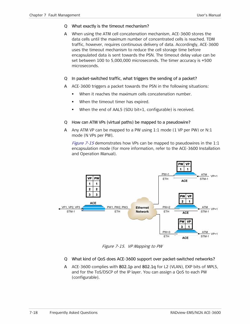
Chapter 7 Fault Management User's Manual
7-18 Frequently Asked Questions RADview-EMS/NGN ACE-3600
Q What exactly is the timeout mechanism?
A When using the ATM cell concatenation mechanism, ACE-3600 stores the data cells until the maximum number of concentrated cells is reached. TDM traffic, however, requires continuous delivery of data. Accordingly, ACE-3600 uses the timeout mechanism to reduce the cell storage time before encapsulated data is sent towards the PSN. The timeout delay value can be set between 100 to 5,000,000 microseconds. The timer accuracy is +500 microseconds.
Q In packet-switched traffic, what triggers the sending of a packet?
A ACE-3600 triggers a packet towards the PSN in the following situations:
When it reaches the maximum cells concatenation number.
When the timeout timer has expired.
When the end of AAL5 (SDU bit=1, configurable) is received.
Q How can ATM VPs (virtual paths) be mapped to a pseudowire?
A Any ATM VP can be mapped to a PW using 1:1 mode (1 VP per PW) or N:1 mode (N VPs per PW).
Figure 7-15 demonstrates how VPs can be mapped to pseudowires in the 1:1 encapsulation mode (for more information, refer to the ACE-3600 Installation and Operation Manual).
ACEPW1, PW2, PW3
ETHVP1, VP2, VP3
STM-1
33
22
11
PWVP
33
22
11
PWVPACE
ACE
PW=2ETH
ATMSTM-1
VP=1
12
VPPW
12
VPPW
ATMSTM-1
VP=1
11VPPW11
VPPW
ACE
ATMSTM-1
VP=1
13
VPPW
13
VPPW
PW=1
ETH
PW=3ETH
EthernetNetwork
Figure 7-15. VP Mapping to PW
Q What kind of QoS does ACE-3600 support over packet-switched networks?
A ACE-3600 complies with 802.1p and 802.1q for L2 (VLAN), EXP bits of MPLS, and for the ToS/DSCP of the IP layer. You can assign a QoS to each PW (configurable).

User's Manual Chapter 7 Fault Management
RADview-EMS/NGN ACE-3600 Technical Support 7-19
Q How can one calculate the required Ethernet bandwidth for a PW based on the ATM parameters?
A Bandwidth utilization depends on the ATM connection rate, mapping methods (VPoPSN or VCoPSN), network type (L2/MPLS or IP), VLAN existence, and number of concatenated cells. You can obtain from Technical Support, a calculator that calculates the bandwidth based on these parameters.
Q How can End-to-End OAM be maintained over a packet-switched network?
A ACE-3600 transfers transparent End-to-End OAM over the PSN. You can set the Intermediate mode for the OAM Descriptor, in order to instruct ACE-3600 to transparently forward the ATM OAM cells as user data over the PSN. For more information, refer to the ACE-3600 Installation and Operation Manual.
Q How does the pseudowire connectivity check (VCCV-BFD) work?
A BFD control messages are generated by both the local and remote ACE units, in both directions of the pseudowire. When the local ACE unit does not receive control messages from the remote ACE unit during a number of transmission intervals, it declares that the PW is down in its receive (RX) direction. The PW then enters a defect forwarding state on the local ACE unit. In addition, the local ACE generates "control-detection-time-expired" packets towards the remote ACE, and the remote ACE replies with "neighbor-signal-session-down" packets. For more information, refer to the ACE-3600 Installation and Operation Manual.
Q What is "Misorder" in the context of packet-switched traffic?
A In packet-switched traffic, some packets are not received according to their predefined sequence number. This condition is defined as misorder. Accordingly, to allow proper de-capsulation of ATM/TDM traffic, ACE-3600 has a mechanism that fixes this condition by reordering the received packets correctly.
You can enable or disable the ordering mechanism, and can also set the 'number of packets' window (0, 1, 2, 4, 8, 16 or 32 packets) in which ACE-3600 tries to fix erroneous packet sequences (misorders). For more information, refer to the ACE-3600 Installation and Operation Manual.
7.5 Technical Support
You can obtain technical support for ACE-3600 from the local distributor from whom it was purchased.
For further information, please contact the RAD distributor nearest you or one of the RAD offices worldwide. You can find this information at the RAD Web site: http://www.rad.com/. For office locations, click About RAD > Worldwide Offices; for distributor locations, click Where to Buy > End Users.

Chapter 7 Fault Management User's Manual
7-20 Technical Support RADview-EMS/NGN ACE-3600

RADview-EMS/NGN ACE-3600 I-1
Index
—1—
1-to-1 configuration, 3-95, 3-98, 4-25, 4-26, 4-27, 4-
28, 4-29, 5-60
—A—
AAL types, 7-17 ACE-3600
EMS HPOV window, 2-3 launching, 2-3 network elements tree window, 2-3 overview, 1-1 preconfiguration, 2-1
Active main module, 3-34 Agent, polling the, 3-117 Alarms
filtering, 7-4 list
closing, 7-5 refreshing, 7-5 saving, 7-5
list of, 7-2 parameters, 7-3 printing, 7-5 system, VP, VC, 7-4 types, 7-4 viewing all active, 7-2
Application level configuration, 1-5 monitoring, 1-8
Application parameter configuration, 4-12 APS
add, 3-42, 4-11 closing table, 5-11 configuration, 3-39, 5-6 details and statistics, 5-6 parameters, 4-10 port switch command, 3-40, 3-41 refreshing statistics, 5-11 remove, 3-43 running statistics, 5-10 settings, 4-11 switch command, 3-43
ATM cross-connect parameters, 3-58 ATM cross-connection
adding, 3-60 configuration, 3-58 removing, 3-64 searching, 3-64 validation, 3-63
ATM cross-connection parameters,changing, 3-63 ATM multiservice over PSN,settings, 4-18 ATM over PSN,application figure, 4-1
ATM PW current cells statistics, 5-50
ATM-155 port protection, 4-10 ATM-155 ports
ATM layer configuring, 3-31 statistics, 5-13, 5-18, 5-22, 5-26
configuration, 4-3 settings, 4-4 SONET/SDH layer, configuration, 3-28
Attachment circuits monitoring, 5-59
Auto Negotiation, 3-28 Automatic protection switching. See APS Autonegotiation, 3-26
—B—
BFD control messages, 7-19
—C—
CC direction, 3-57 CDVT, 3-49, 4-17 Cell test, 7-14
close, 7-15 parameters, 7-15
Central gateway, 4-2 Chassis, 1-1 Clock configuration, 3-45 Clock source configuration, 4-30 Commands, accessing
port level, 2-6 system level, 2-5
Configuration application, 4-12 application level, 1-5 APS, 3-39 APS parameters, 4-10 ATM attachment circuit, 4-24 ATM cross-connection, 3-58 ATM-155 port protection, 4-10 ATM-155 ports, 3-28, 4-3 clock source, 4-30 date and time, 3-4 device information, 3-2 device level, 1-3 Ethernet port, 3-24, 4-6 Ethernet redundancy, 3-36, 4-8 GbE ports, 3-26, 4-5 general multiservice PW over PSN, 4-17 label range, 3-76 LDP, 3-77
interface, 3-79 targeted peers, 3-82

Index User’s Manual
I-2 RADview-EMS/NGN ACE-3600
LSP tunnel egress, 3-86 ingress, 3-84
main card redundancy, 3-34 manager, 4-31 MPLS parameters, 3-75 multiservice over PSN, 3-89 OAM, 3-53 OAM loopback parameters, 3-53 operational parameters, 3-24 OV severity, 3-22 peer, 4-18 physical layer, 4-3 port level, 1-5 protection parameters, 3-33, 4-7 pseudowire, 4-19
general, 4-20 PSN, 4-21 service, 4-22
PW connections, 3-94 router, 3-64
interface, 3-66 parameters, 3-65
router interface, 4-12 stages, 4-2 static route, 3-72 STM-1/OC-3c, 4-10 summer time, 3-8 syslog server, 3-11 system information, 3-2 system level, 1-3 system parameters, 3-2 system redundancy, 4-7 traffic descriptors, 4-15
Congestion dropped, 5-37, 5-41 Control word,enable/disable, 3-99, 4-25, 4-26, 4-
27, 4-28, 4-29 Control-detection-time-expired packets, 7-19 Correct bytes, 5-37, 5-40, 5-42 Cross connections,ATM, 3-58 Current statistics, general description, 5-1
—D—
Date and time configuration, 3-4 Net, 5-3 parameters, 3-5 synchronization, 5-3 validation, 3-7
Daylight saving time, 3-5 Default configuration,restoring, 3-118 Default gateway,settings, 4-15 Default main card, 4-8 Default main card, 3-35 Defect forwarding state, 7-19 Device image,LED indicators, 7-16 Device information, configuration, 3-2 Device level
configuration, 1-3 fault detection, 1-9 monitoring, 1-7
Diagnostic tests, 7-9, 7-11, 7-12 loopback test, 7-11, 7-12
dialog box, 7-13
self test, 7-9
—E—
Elapsed time, 5-51, 5-53, 5-55, 5-58 EMS admin console, 6-2 EMS admin console,EMS security administrator, 6-3 EMS security administrator, 6-3 EMS security console, 6-2 End-to-End OAM, 7-19 Ethernet redundancy
add, 4-10 configuration, 4-8
Ethernet bandwidth, 7-19 Ethernet port
configuration, 3-24, 4-6 configuring parameters, 3-25 monitoring, 5-42 settings, 4-7 viewing information, 5-43
Ethernet redundancy add, 3-38 configuration, 3-36, 4-8
—F—
Fallback clock, 3-45 settings, 4-31
Fault detection device level, 1-9 port level, 1-10 system level, 1-9
Fault management, 7-1 object status monitoring, 7-1
FCAPS, 1-3 FCS errors, 5-37, 5-40 FM SES, 5-22 FM UAS, 5-22 Frequently asked questions, 7-17
—G—
Gateway central, 4-2 remote, 4-2
GbE ports configuration, 3-26, 4-5 configuring parameters, 3-27 current Rx statistics, 5-36 current Tx statistics, 5-38 intervals Rx statistics, 5-39 intervals Tx statistics, 5-41 monitoring, 5-34 settings, 4-6 statistics, 5-36 viewing information, 5-34
General multiservice PW over PSN configuration, 4-17
Getting started, 2-3 Gigabit Ethernet 1, 1-2 Graph
appearance, 5-3 customization, 5-3 horizontal axis
current, 5-2 intervals, 5-2
User’s Manual Index
RADview-EMS/NGN ACE-3600 I-3
time elapsed, 5-2 tooltips, 5-4 vertical axis, 5-2
Graph hidden parameters, 5-4
Graph line bold display all, 5-4 invisible, 5-4 options, 5-4 regular, 5-4
Graphs legend, 5-3
GUI port level, 2-6, 2-7
menu bar, 2-7 port layers, 2-7 window, 2-6 zoom In button, 2-6
system level, 2-5 device image, 2-5 menu bar, 2-5 poll agent button, 2-6 status bar, 2-6 system info button, 2-6 title bar, 2-5 toolbar, 2-6
using the, 2-5
—H—
Hardware options, 1-1 Hello message statistics, 5-64 History log
clearing, 7-8 closing, 7-8 printing, 7-7 refreshing, 7-8 saving, 7-7 viewing, 7-5 viewing from specific entry, 7-8 viewing next page, 7-8
HPOV map icon colors, 7-1
—I—
Icons device, 2-3 element tree, 2-3 zoom, 2-3
Interface module, types, 1-2 Interface, using, 2-5 Intermediate mode, 7-19 Intervals statistics, general description, 5-1 IP address,peers, 3-92 IP mask, 3-68, 3-71
—L—
Label range,configuration, 3-76 LDP
configuration, 3-77 hello message statistics, 5-64 interface
configuration, 3-79 label statistics, 5-61
monitoring, 5-60 session statistics, 5-66 single label statistics, 5-62 targeted peers
configuration, 3-82 LED indicators, 2-8, 7-16
fan tray, 2-8 hot-swappable power supplies, 2-8 main module, 2-8 MNG-ETH control port, 2-9 station clock port, 2-9
License packs, 1-3 License status, 5-67 LOC, 5-22 Log buffer. See System log buffer Loopback
external, 7-14 internal, 7-14
loopback test, 7-11 Loopback test
loopback timeout, 7-11 port level
parameters, 7-13 Loopback timeout, 7-11
dialog box, 7-11 parameters, 7-12
LSP tunnel egress
add, 3-87 change, 3-88 configuration, 3-86 remove, 3-89
ingress add, 3-84 change, 3-85 configuration, 3-84 remove, 3-86
LSR, 5-60
—M—
Main card options see Main module
options, 1-2 Main card redundancy
configuration, 3-34 configuration, 4-8 settings, 4-8
Main module default, 3-35, 4-8 name and type, 1-2 options, 1-2 resetting the standby, 3-36 software update, 3-36
Management via ATM port, 2-2 via LAN, 2-1 via packet-switched network, 2-2
Management station connecting to, 2-1
Manager adding, 3-14, 4-31 IP, 3-14 IP address, 4-31 list, 3-12

Index User’s Manual
I-4 RADview-EMS/NGN ACE-3600
mask traps, 4-32 validation, 3-15
Map icon colors, 7-1 HPOV, 7-1 SNMPc, 7-1
Mask traps, 4-32 Masking traps, 3-16
parameters, 3-17 Master clock, 3-45
settings, 4-31 MBS, 3-49 MC-155-4/GBE, 1-2 MDCR, 3-50 Menu bar
port level, 2-7 system level, 2-5
Misorder definition, 7-19
Misorder, 3-91 Misorder setting, 3-91 Modules
interface options, 1-2 main, 1-2
Monitoring application level, 1-8 device level, 1-7 port level, 1-7 system level, 1-7
MPLS, 5-60 configuration, 3-75
Multiservice over PSN configuration, 3-89
Multiservice over PSN traffic monitoring, 5-44
—N—
Neighbor-signal-session-down packets, 7-19 NMS,connecting to, 2-1 N-to-1
configuration, 3-95, 3-98, 4-25, 4-26, 4-27, 4-28, 4-29, 5-60
Number of packets window, 7-19
—O—
OAM configuration, 3-53 descriptor
changing, 3-57 removing, 3-57 vallidation, 3-58
descriptors adding, 3-56 parameters, 3-55 table, 3-54 viewing, 3-54
loopback parameters configuration, 3-53
parameters, 3-54 viewing, 3-54
OAM descriptor, 3-71 Object status monitoring, 7-1
active alarms, 7-2 map icon colors, 7-1
Operational parameters,configuration, 3-24
OV severity, configuration, 3-22
—P—
Packet sending, 7-18 Password,changing, 6-2 PCR, 4-17 Peak cell rate, 3-49 Peer
add, 3-93, 4-18 change, 3-93 configuration, 4-18 settings, 4-19
Peers, 3-91 Performance monitoring, 5-1 Performance monitoring operations, 1-7 Permission
hierarchical tree, 6-4 hierarchy, 6-4 setting, 6-4
Physical layer, configuring, 3-24 Poll button, 5-2 Polling interval, setting, 5-4 Polling the agent, 3-117 Polls,formula for calculating number of, 5-3 Port layer, selecting, 2-7 Port level
configuration, 1-5 fault detection, 1-10 monitoring, 1-7 windowr, 2-6
Port level commands, accessing, 2-6 Port level diagnostics, 7-12
loopback test, 7-12 dialog box, 7-13
Port status Ethernet, 5-43 GbE, 5-34
Port type, 3-46 Power supplies, 1-2 Product
options, 1-1 overview, 1-1
Protection parameters configuration, 3-33, 4-7
Pseudowire ATM attachment circuit configuration, 4-24 configuration, 4-19 connection statistics, 5-47 connection status, 5-44 current cells statistics, 5-50 current packets statistics, 5-52 general configuration, 4-20 intervals cells statistics, 5-54 intervals packets statistics, 5-56 links, 4-19 mapping, 7-18 PSN configuration, 4-21 service configuration, 4-22 status, 5-44 table, 4-20
PSN parameters general, 3-90 peers, 3-91
PSN parameters, 3-89

User’s Manual Index
RADview-EMS/NGN ACE-3600 I-5
PW add, 3-96 ATM attachment circuit parameters, 3-106 ATM service parameters, 3-103 attachment circuit
add, 3-108 change, 3-111 remove, 3-112
clock distribution ACE-3100, 4-25 clock distribution ACE-3200, 4-27 configuration. See Pseudowire:configuration connections configuration, 3-94 data for VC (0/100), 4-26 data for VC (0/200), 4-29 data for VP (100), 4-26 data for VP (200), 4-28 general parameters, 3-96 number, 3-97, 3-101, 3-104, 3-106 PSN parameters, 3-100 type, 3-95, 3-98, 4-25, 4-26, 4-27, 4-28, 4-29,
5-60
—Q—
QoS, 7-18
—R—
RAD distributor locations, 7-19 office locations, 7-19 Web site, 7-19
Redundancy statuses, 3-34 Remote gateway, 4-2 Reset procedure, 3-118 Restore configuration, 3-118 Router
configuration, 3-64 interface
add, 3-68 configuration, 3-66
parameters configuration, 3-65
Router interface add, 4-14 configuration, 4-12 settings, 4-14 table, 4-13
Router interface parameters, 3-69 Rx
RDI, 5-22 RX
Ethernet statistics, 5-37, 5-40, 5-42
—S—
SCR, 3-49 Security management, 6-1 Security profile
definition, 6-3 setting, 6-3
Self test, 7-9 dialog box, 7-10 parameters, 7-10
Self test dialog box close, 7-11
refresh, 7-11 Service category, 3-47 Severity level, 3-12 Shaping mode, 4-17 Shaping parameters, 3-47 SNMPc map
device icon colors, 7-1 frame colors, 7-1
SNMPc window, 2-3 SNMPv3
enabling, 6-5 SNTP time retrieval, 3-6 software files
viewing, 5-68 Software files
swapping, 3-119, 3-120 viewing, 3-119
Software license, 1-3 Start time, 5-51, 5-53, 5-55, 5-58 Static entry
removing, 3-75 Static route
adding, 3-73 configuration, 3-72
Statistics APS, 5-6 APS Running, 5-10 ATM XC, 5-12 graph characteristics, 5-2 overview, 5-1 port level
ATM layer, 5-29 physical layer
ATM-155, 5-13, 5-18, 5-22, 5-26 system level
ATM XC, 5-12 polling interval, 5-4
types, 5-1 Status bar, 2-6 STM-1/OC-3c UNI 4, 1-2 Summer time configuration, 3-8 Switch command, 3-40, 3-41, 5-8 Syslog statistics, 5-69 System configuration, 3-2 System information, 2-6
configuration, 3-2 drop-down calendar, 3-7 modifying, 3-3 parameters, 3-3, 3-8, 3-9
System level configuration, 1-3 fault detection, 1-9 monitoring, 1-7
System level commands, accessing, 2-5 System level diagnostics, 7-9, 7-11
loopback test, 7-11 self test, 7-9
System log buffer buttons and parameters, 7-7 clearing, 7-9 date and time, 7-7 dialog box, 7-6
System redundancy configuration, 4-7

Index User’s Manual
I-6 RADview-EMS/NGN ACE-3600
—T—
Targeted peer mode, 3-83 Technical support, 7-19 Telnet access, displaying status, 3-23 Time elapsed, 5-31 Timeout delay value, 7-18 Timeout mechanism, 7-18 Timer accuracy, 7-18 Toolbar, 2-6 Traffic descriptor, 3-71
add, 4-16 adding, 3-50 changing, 3-52 configuration, 3-47, 4-15 parameters, 3-48 removing, 3-53 VCoPSN
settings, 4-17 VPoPSN
settings, 4-16 Traffic descriptor
viewing, 3-48 Traffic descriptor
validation, 3-53 Traffic descriptors
viewing, 4-15 Traffic switch
double, 3-126 single, 3-121
Traps masking, 3-16 masking parameters, 3-17
Troubleshooting, 7-16 Tx
RDI, 5-22 TX
Ethernet statistics, 5-39 Typical configuration, 4-1
—U—
User
adding, 6-1 administrator, 6-1 monitor, 6-1 operator, 6-1 permissions, 6-1 technician, 6-1
User interface, 2-5 Username,changing, 6-1
—V—
VC OAM current statistics, 5-18 intervals statistics, 5-20 loopback current statistics, 5-22 loopback intervals statistics, 5-24
VC user current statistics, 5-13 intervals statistics, 5-16
VCI, 3-70 VCoPSN settings, 4-17 VLAN
ID, 3-72 priority, 3-72 tagging, 3-72
VP mapping, 7-18 VPI, 3-70 VPoPSN settings, 4-16
—W—
Web access, displaying status, 3-23 WTR time, 4-8 WTR time, 3-35, 3-40 WTR time, 4-11
—X—
XC ATM, 3-58
—Z—
Zoom into port, 2-6 Zoom to device, 2-4