Embed Size (px)
Citation preview

December 2018 Technical tips on lubricants and lubrication methods for power plant maintenance and engineering personnel
ELECTRIC POWERRESEARCH INSTITUTE
Radionuclides in Oil—Tritium, Carbon-14, and Other Hard-to-Detect Radionuclides Query: My site recently received a notice from the Nuclear Energy Institute concerning regulatory compliance of
10CFR 20.1501—Surveys and Monitoring for Free Release of Contaminated Oil. Specifically, the notice was for
fleet radiation protection managers, noting that if they were not doing the H-3 and C-14 analyses with gamma
analyses, they should do so in order to be in compliance with regulations. Is this a new regulation?
Response: No, this is not a new regulation. The
U.S. Code of Federal Regulations (CFR)—in
particular, 10CFR20—addresses standards for
radiation protection and has existed for many,
many years. Waste oil that is generated during
normal plant operations has the potential to be
radiologically contaminated when a credible
pathway exists for the oil to come in contact
with radionuclides. Currently, there is no
standard process for evaluating tritium and
carbon-14 in oil; so, there is variability in how
plants are determining whether oil contains tritium and carbon-14 and the potential impact on meeting the free
release criteria as defined in 10CFR20 [1, 2].
Analysis: The U.S. Nuclear Regulatory Commission (NRC) is increasing its regulatory scrutiny regarding free
release practices to ensure that the utilities are evaluating oil for all plant-produced radionuclides prior to free
release. The NRC has indicated that the requirement to conduct adequate surveys should include evaluating oils
for tritium and carbon-14, and failure to do so may constitute a violation of regulations.
The EPRI Radiation Safety Program has a project to review, identify, and provide information on how to evaluate
used oils related to free release through a plant-specific system analysis, identification of sample requirements,
and an attempt to identify the key considerations related to the application of process knowledge to free release
oils. A small working group of industry radiation protection specialists has been established to provide feedback
Note Number 1
Lube Notes…EPRI's Nuclear Maintenance Applications Center (NMAC) is pleased to present another in our series of Lube Notes.
If you have questions regarding these notes or lubrication practices in your plant, contact Nick Camilli, EPRI, 1300 West W.T. Harris Blvd., Charlotte, NC 28262, 704.595.2594, [email protected].
Also in This Issue... Oil Sight Glass Issues ....................................................................... 2
Phosphate Ester EHC Elastomer Compatibility ....................................... 5
How Well Do You Know Your Lube Oil Blending Facility? ...................... 9
Avoiding EHC Fluid Problems ...........................................................11
Recent Product Line Updates ............................................................ 14
Review of ASTM International Update on D02 Petroleum Products, Liquid Fuels, and Lubricants .............................................................................. 17
continued on page 2
10230027

Lube Notes 2 December 2018
continued on page 3
and information for the EPRI project. The project includes a review of the U.S. regulatory guidance, previous EPRI
research efforts, site-specific nuclear power plant practices, and laboratory capabilities. It is anticipated that the
results of this work can be applied at nuclear power stations in the development of site-specific free release guidance
of waste oils. The report is anticipated to be published by the first quarter of 2019.
Conclusions: The NRC has indicated that the requirement to conduct adequate surveys should include evaluating
used/waste oils for gamma, tritium, and carbon-14. This practice is currently not consistently applied across the
industry. The EPRI report is intended to provide plant staff with information related to the system analysis, sampling,
and the application of process knowledge to evaluate used/waste oil free release. Site-specific free release procedures
can be established using the basic approach and information described described in the EPRI report. Plant staff
should talk to their respective radiation protection manager for specific guidance on station or corporate polices.
References
1. "Surveys and Monitoring," Section 1501, U.S. Nuclear Regulatory Commission, Washington, D.C.: 2017.
10CFR20.1501, Subpart F.
2. "Compliance with Environmental and Health Protection," Section 2007, U.S. Nuclear Regulatory
Commission, Washington, D.C.: 2017. 10CFR20, Subpart K.
Radionuclides in Oil—Tritium, Carbon-14, and Other Hard-to-Detect Radionuclidescontinued from page 1
Note Number 2
Oil Sight Glass Issues
Query: Can a safety-classified mitigating system be unavailable as a result of an inadequate installation of oil sight
glasses and inappropriate oil level?
Response: Yes, it is a common issue that tends to occur from time to time. In June 2018, the Nuclear Regulatory
Commission (NRC) issued Information Notice 2018-07: Pump/Turbine Oil Sight Glass Problems. The intent of
the Information Notice is to inform stations of the importance of establishing proper oil levels in pump reservoirs
and other rotating equipment. Inadequate oil levels lead to insufficient lubrication of bearings, thereby increasing
temperatures, accelerating oil degradation, and, if not caught in time, ultimately resulting in failure. Although
safety-significant systems such as auxiliary feedwater, emergency diesels, and safety injection are the focus of the
Information Notice, the practices presented within are good practices for all splash oil lubrication systems with
external mounted oil level indicators.
Analysis: Three main causes of examples were cited in the Information Notice. This Lube Note covers each
example and elaborates on best practices and experiences that EPRI has acquired over the years.
Incorrect Markings on the Oil Level Sight Glass
As simple as it sounds, it’s an easy mistake to make that occurs frequently. This issue predominantly occurs in
splash oil lubrication systems (known as oil rings or slinger rings). These applications operate by rings riding on the
shaft or journal hanging down into the oil in the reservoir/sump. As the shaft rotates, the oil rings rotate, picking
up oil and carrying (or splashing) it onto the bearings/gears for lubrication. The sight glass for these applications is
external to the reservoir and a columnar design, often with high and low oil level markings. Operating experience
indicates numerous issues where the oil level markings were incorrect (auxiliary feedwater turbine applications are
most common). If the oil level is too low, excessive temperatures can occur from insufficient boundary lubrication.
If the oil level is too high, excessive temperatures can occur from oil churning and aeration. For reservoirs in which
oil rings are used, a general rule is for the rings to be set with the oil level 1/4–3/8 in. (6.4–9.5 mm) from the
bottom inside of the ring. Always consult your manufacturer for specifics on your application.
10230027

Lube Notes 3 December 2018
continued on page 4
Oil Sight Glass Issuescontinued from page 2
Inverted Sight Glass
Typically, when field operators, maintenance technicians, or system/component engineers walk by a component
and check the oil level, one does not think about the likelihood of the oil sight glass being inverted as a result of a
recent surveillance or maintenance activity. However, operating experience shows that it has happened. An inverted
sight glass with level markings on it will obviously give a false indication of oil level, either creating excessive oil
in the reservoir or a lower than recommended level. The best ways to avoid such an issue are to ensure that proper
procedure controls are in place during maintenance evolutions and general training/awareness on the topic.
Maintaining Proper Oil Level
Although maintaining proper oil level is a generic statement, there are really two issues at hand.
First, some of the components where oil samples are taken have small oil reservoirs. In this situation, the task of
pulling the sample can challenge the minimum amount of oil required for operation and cause the equipment
to be inoperable. If the oil volume is not restored to the appropriate level immediately prior to the sample being
collected, the component could trip on low oil alarm and/or lead to bearing damage. There have been multiple
instances of this occurring at stations across the world. It is important for the risk to be understood and to have
proper controls (that is, a procedure that specifies the maximum oil sample to be collected) in place to reduce the
likelihood of such an event.
Secondly, oil levels should always be between the high and low level markings (see Figures 1 and 2). Just because
the oil level is visible in the sight glass does not alone mean that the level is adequate or acceptable. The level
should always between the high and low level markings. Anything otherwise has the potential to challenge the
operation of the component, which is potentially unfavorable in safety-related components. This situation has led
to the NRC issuing findings for some stations. One extremely important note to add concerning this topic: do not
assume that markings are correct when installing a new sight glass. These sight glasses can be generic and installed
on various components; therefore, markings need to be verified against the proper oil level for your application.
There are many stations where personnel learned this lesson the hard way, unfortunately.
Figure 1 General recommendation for oil level settings for oil ring application
10230027

Lube Notes 4 December 2018
Oil Sight Glass Issuescontinued from page 3
Conclusions: There are several key takeaways to help avoid oil sight glass issues. Start with the basics. Maintenance
procedures need to reflect the installation of the sight glass in the proper orientation. The procedures also need to
verify that the oil level is correct. Specifically, the oil level marking on the sight glass reflects the amount in the
reservoir, and that amount is indeed adequate for bearing lubrication. There have been instances in the industry
Figure 2 Importance of oil level to be between high and low level
where there were discrepancies between the original equipment manufacturer drawings and the vendor manuals.
When oil samples are collected, procedures should raise awareness to the risk of inop’ing a system because of low
level while providing proper instruction on appropriate sample collection amount for the specific application.
Discussion on this topic can be found in the 2009 EPRI report, Nuclear Maintenance Applications Center: Oil
Lubrication Guide for Rotating Equipment (1019517). This report covers constant level oilers and splash oil
lubrication system setup and maintenance. Also, there is a section on component-specific equipment, including
Terry Turbines, which have been vulnerable to constant oil leveler issues in the past. This topic is frequently
covered in EPRI/industry user groups (Condition-Based Maintenance Users Group, Terry Turbine Users Group,
and Pump Users Group), which are always good forums in which to share lessons learned.
References
1. Information Notice 2018-07: Pump/Turbine Bearing Oil Sight Glass, U.S. Nuclear Regulatory
Commission, Washington, D.C: June 13, 2018. https://www.nrc.gov/docs/ML1733/ML17332A541.pdf
2. Nuclear Maintenance Applications Center: Oil Lubrication Guide for Rotating Equipment. EPRI, Palo Alto,
CA: 2009. 1019517.
10230027

Lube Notes 5 December 2018
continued on page 6
Phosphate Ester EHC Elastomer Compatibility
Note Number 3
Phosphate Ester EHC Elastomer CompatibilityQuery: How do I know which elastomers are compatible with my electrohydraulic control (EHC) fluid?
Response: Phosphate esters have many advantages and can be good plasticizers; so, some commonly used materials
for mineral oils such as Buna N1 and neoprene should not be used (see a more complete list in Conclusions section
and in Table 1). These materials tend to soften, get sticky, and/or fall apart, resulting in loss of sealing and/or the
migration of debris. Operating experience has reported problems with hoses, O-rings, paints, filter elements, and
accumulator bladders caused by failed elastomers (see Figures 1–3). Guidance is available in References 1–5 and
also in the elastomer supplier’s data.
Analysis: This is not just a phosphate ester issue because ethylene propylene rubber (EPR) and butyl rubber are
suitable for phosphate esters but not for mineral oil. Use the specified elastomers for the application, and, if changes
are being made, verify the compatibility with the fluid supplier and with the elastomer supplier. If still not sure,
test. Compatibility is often determined by immersing a sample of the material in the fluid and soaking it at an
elevated temperature. One suggestion by General Electric (GE) [5] is to soak a piece of the elastomer in the fluid
for 168 hours at 60°C (140°F). See also ASTM D4289 [6]. GE limits are 15% swell and/or 5% shrinkage. Note:
this may not be adequate criteria for long-term exposure to the fluid, especially at elevated temperatures. Even with
approved materials, there can be some effect. Also, some materials with very good compatibility might not be as
elastic or might be more prone to taking cold sets. Examine all the properties when making a change, including
any degradation in tensile strength.
The various brands of triaryl phosphate esters used as EHC fluid are similar with respect to material compatibility.
However, not all elastomer compounds are necessarily the same because elastomer suppliers can have different
blends. There can also be various versions of the same family, such as Viton2 A, B, and GF. The major differences
in Viton grades involve the amount of fluorine. Higher fluorine content results in better compatibility with triaryl
phosphates. In addition, the temperature of the application is very important. The higher the temperature, the
greater the effects.
Material Compatible to °C (°F)Butyl 105 (225)
Fluorocarbon* 150 (300)
EPR, ethylene propylene diene monomer 150 (300)
Polytetrafluoroethylene ** 175 (350)
Silicone rubber 175 (350)
Nylon 120 (250)
Table 1 Temperature effects on compatibility for various elastomers [3]
* For example, Viton, Kalrez3, Fluorel4
** For example, Teflon5
1 Buna N is a registered trademark of Pittway Corporation.2 Viton is a registered trademark of Du E.I. du Pont de Nemours & Co.
10230027
Lube Notes 6 December 2018
Phosphate Ester EHC Elastomer Compatibilitycontinued from page 5
continued on page 7
Fortunately, there are many materials
that are acceptable (see Table 2 [4]).
In addition, check with your fluid
supplier for your specific application
because some elastomers that mighty
not be affected dimensionally could
release compounds that might be a
problem. For example, silicone can
increase the air release time of some
fluids. Similarly, some chlorinated
elastomers might affect resistivity.
The suitability of a particular
compound depends on the material
and the application. For example, in
one application some swell might be
acceptable, whereas in others it might not. It is generally acceptable with captured seals such as some gaskets but
not parts where there is motion. Also, with hoses—although the material might be given as being acceptable—it
can still leak fluid that can lead to sweating on the outside and/or blistering. Similarly, for hoses being used for
suction conditions such as the fluid supply to a pump the liner must be rated for suction conditions.
In addition, silicone-based rubber and/or sealants might be unsuitable in contact with EHC fluids but are
reportedly acceptable as a coating for wires. This is not because of softening—when such material is exposed to
the fluid, there have been reports of adverse effects on the air release time of the fluid. In susceptible systems it can
lead to more rapid fluid degradation because of excessive air being pulled into the pump suction.
There can be considerable differences between the recommendations from component suppliers. One problem in
checking with component suppliers is that the fluids can be listed under a variety of names. If there is difficulty,
try looking under some of the following:
Trade names: Fyrquel6, Durad, Reolube7 Turbofluid, Anvol8 PE, Hydran9 FR, Pyrogard10 53 or 53T,
Houghto-Safe11 1120, or Kronitex12 (All are triaryl phosphate esters, but not all are EHC quality fluids.)
Chemical names: industrial phosphate ester (PE), triaryl phosphate (TAP), tricresyl phosphate (TCP),
trixylenyl phosphate (TXP), tertiary-butylphenyl phosphate (TBP), and triphenyl phosphate (TPP)
3 Kalrez is a registered trademark of E.I. du Pont de Nemours & Co.4 Fluroel is a registered trademark of 3M Company.5 Teflon is a registered trademark of E.I. du Pont de Nemours & Co.6 Fyrquel is a registered trademark of ICL.7 Reolube is a registered trademark of Chemtura.8 Anvol is a registered trademark of Castrol.9 Hydran is a registered is a registered trademark of General Electric Company.10 Pyrogard is a registered trademark of Millipore Corporation.11 Houghto-Safe is a registered trademark of Houghton International, Inc.12 Kronitex is a registered trademark of FMC13 Skydrol is a registered trademark of Solutia, Inc.
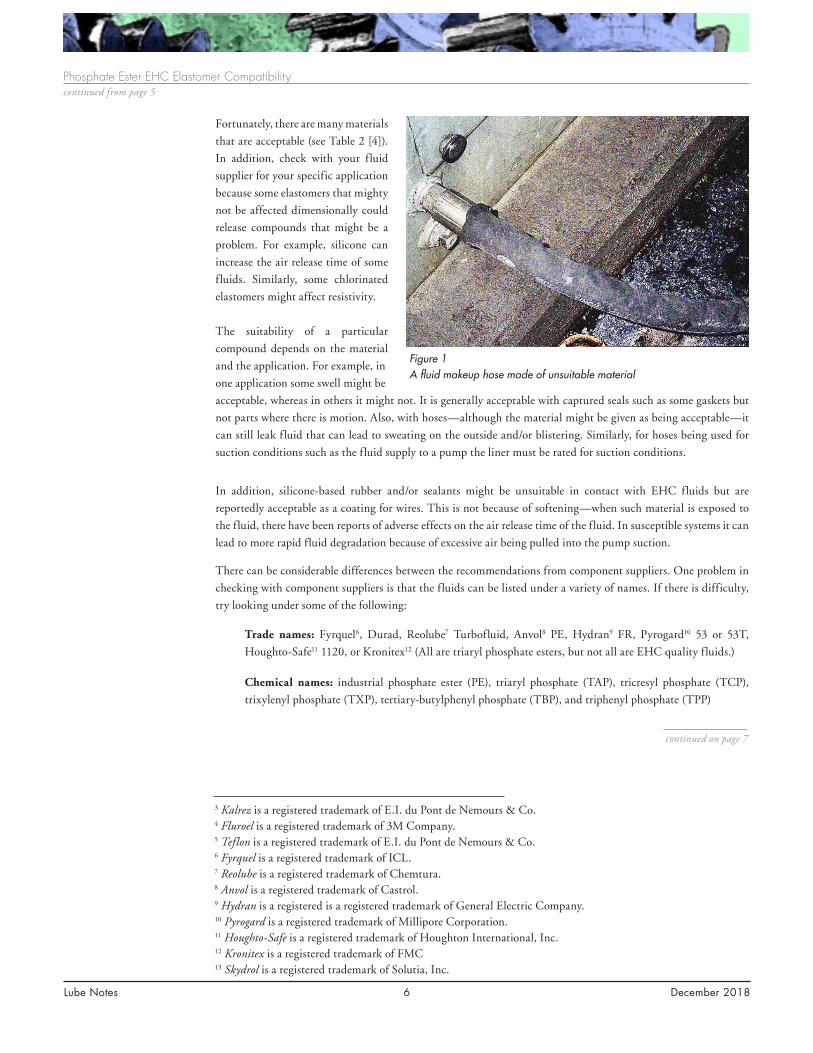
Figure 1 A fluid makeup hose made of unsuitable material
10230027

Lube Notes 7 December 2018
Phosphate Ester EHC Elastomer Compatibilitycontinued from page 6
Figure 2 Blistering on a reportedly compatible material
Figure 3 Pieces of an accumulator in a check valve
continued on page 8
Caution: Trialkyl phosphate esters such as Skydrol13 used in aircraft hydraulics are a different type and are
not generally compatible with fluorinated elastomers. Triaryl phosphates as used for turbine EHC systems are
acceptable with triaryl phosphate ester EHC fluids.
Conclusions: It is important to use compatible materials in any application and especially in EHC systems.
For parts and overhauls, it is not generally good enough to just say use compatible materials; instead, specify which
ones are acceptable. Depending on the application, the following should be acceptable for O-rings and hoses:
fluorocarbons, PTFE, ethylene propylene, and butyl rubber. The following should not be used: Buna-N, nitrile
rubber, natural rubber, neoprene, polyvinyl chloride, polyurethane, and polyacrylates.
10230027

Lube Notes 8 December 2018
Seals, hoses and bladders
Wire and cable
insulationPaints
Sample bottles and
caps*
Acrylic U
Alkyd paint A
Butyl rubber R
Cellulose ** A (liners)
EPR R
Epoxy paint (cured) A
Glass A
Fluorocarbon (Viton, Kalrez, Fluroel) R
Natural rubber U
Neoprene U
Nitrocellulose lacquers U
Nitrile rubber U
Nylon R A
Phenolic resins U
Polyethylene A A
Polypropylene A
Polyethylene terephthalate A
Polyurethane paint A
PTFE, Teflon
Polyvinyl chloride U
Silicone rubber U A
Teflon R R
Vinyl ester paint A
Viton rubber R
Table 2 Acceptable materials
* For sample bottles, make sure that the cap and cap liner are also compatible.
** Some types of cellulose might have binders to hold the fibers together, which must also be suitable.
R = recommended; A = acceptable; U = unsuitable
Phosphate Ester EHC Elastomer Compatibilitycontinued from page 7
continued on page 9
10230027

Lube Notes 9 December 2018
Phosphate Ester EHC Elastomer Compatibilitycontinued from page 8
Note Number 4
continued on page 10
References
1. Electrohydraulic Control (EHC) Fluid Maintenance Guide. EPRI, Palo Alto, CA: 2014. 3002003594
(Section 6).
2. Electrohydraulic Control Fluid and Elastomer Compatibility Guide. EPRI, Palo Alto, CA: 2005. 1011823.
3. ICL Compatibility Guide: Fyrquel Fire-Resistant Fluids and Lubricants.
4. Lanxess Reolube Turbofluid 46B Fire-Resistant EHC Fluid Data Sheet.
5. General Electric, GEK 46357G, Steam Turbine-Generator EHC Fluid Specification and Maintenance,
Section IX, September 2012.
6. ASTM D4289 ¬– 13(2014)e1, Standard Test Method for Elastomer Compatibility of Lubricating Greases
and Fluids.
How Well Do You Know Your Lube Oil Blending Facility?
Query: Should I be knowledgeable about
my lube oil blending facility? Generally,
I have a spec, send it to my supplier, and
they send me an oil that meet the spec
with all the procurement requirements.
Response: The short answer is yes—
absolutely. Knowing where your oil
came from and how it was made can
yield good insights into potential
performance issues in the future. After
all, you wouldn’t buy a reconditioned
automobile that had been previously
titled as flooded, would you?
Analysis: The EPRI Condition-Based Maintenance Users Group (CBMUG) made a stop at Lubrication Engineers
oil blending facility in Wichita, Kansas, prior to the start of the 2018 meeting (see Figures 1 and 2). There
were more than 20 utility participants, none of whom had ever visited an oil blending facility. To say that the
participants gained extensive knowledge would be an understatement.
For this trip, the focus was not on Lubrication Engineers but rather the oil manufacturing process. Visiting the
facility, witnessing each step in the process, meeting the people, witnessing quality control measures—these are
important data points to consider when purchasing your oil. And the value added is walking away with knowing
the right questions to ask, as follows:
• Where does the base oil come from, and is the source consistent?
• Are the drums cleaned and/or rinsed prior to fill up?
• After a batch of oil is made, how long does it sit in the pot/kettle?
Figure 1 The correct progression of oil drum rotation
10230027

Lube Notes 10 December 2018
How Well Do You Know Your Lube Oil Blending Facility?continued from page 9
• What is the method for measuring additives? Precise measurement or human measurement?
• What are the control measures for ensuring product cleanliness and appropriate additive addition?
• Is each batch of oil tested before it leaves the facility? What tests are performed, and what are the acceptance criteri?a
• Is the lubricant storage in a climate controlled environment?
• Is the blending facility clean, in general?
• Is each drum/container labeled with the batch date visible?
• Are the drums/containers appropriately sealed?
• Does the facility practice first-in, first-out rotation of lubricants (see Figure 3)?
Many of these questions may sound familiar because they are general lubrication questions. For example, the
2002 EPRI report, Lube Oil Predictive Maintenance, Handling, and Quality Assurance Guideline (1004384) covers
lubricant storage requirements for power plants. However, the material covered is directly applicable to oil blending
facilities and supplier facilities as well.
Conclusion: There is certainly value to be added to visit or at least ask questions about your lube oil original
equipment manufacturer blending facility. The knowledge gained will not only equip you with insights into how
your product is made, it but will also equip you with knowing the right questions to ask when lubrication products
are being purchased.
Figure 2 Discussing the shipping process on new batches of oil during the CBMUG Lubrication Engineers tour
continued on page 11
10230027

Lube Notes 11 December 2018
Note Number 5
continued on page 12
How Well Do You Know Your Lube Oil Blending Facility?continued from page 10
Figure 3 Discussing the tanker-filling process during the CBMUG Lubrication Engineers tour
Avoiding EHC Fluid Problems
Query: How do I avoid EHC fluid problems?
Response: The short answer is taking the right actions at the right time. But what is right? Phosphate ester
electrohydraulic control (EHC) fluids are capable of trouble-free operation lasting for decades. This requires being
proactive and correcting adverse trends before consequential damage occurs. Being trouble-free involves many
aspects, including supply, maintenance, and operation, as well as equipment deterioration. Things will happen and
although most are common, troubleshooting the odd one will benefit from a good knowledge of what is normal. In
other cases, the fluid might be getting drained every five years or so and/or giving continual problems. These cases
tend to be much costlier and involve more operational risk and/or spills.
Causes of fluid problems are generally relatively easy to fix. The following are generic recommendations for more
problem-free operation.
• Make sure that the technical data and specification materials from the turbine and fluid suppliers are up to date. We have seen, and continue to see, stations following outdated information.
• Trend plot-measured parameters from the fluid test reports if not already done by your lab. If this is not an option, have your lab also provide the previous results.
• Have the lab test results include all targets and the limits. These should be based on the turbine original equipment manufacturer (OEM) recommendations, those from the fluid supplier, EPRI, the Institute of Nuclear Power Operations, and site experience. Revise as required.
• Make sure that the lab is performing all the required tests as specified and by the right procedures. Most do not.
10230027

Lube Notes 12 December 2018
Avoiding EHC Fluid Problemscontinued from page 11
• Benchmark the actual maintenance being performed versus the recommended maintenance at a yearly interval. Reviewing completed work packages and warehouse withdrawals is often very helpful. Warehouse withdrawal reviews can be particularly useful to ensure that the work is being completed as required. It can also serve as a check on what has been ordered/delivered
• Ensure that maintenance procedures are correct. Spend time in the field helping new staff or staff doing a job for the first time to do it right. Many common tasks, such as trap filter changes, are not simple or obvious. In fact, it is easier to do them wrong than right. Fortunately, maintainability can be improved at very little cost with such components as air release valves and/or better filters.
• Have at least weekly system walkdowns and checks on system status, including the pressure drops across all filters and purification media, fluid temperature, and fluid level. Hopefully, they are being trended by operations and not just reacting to alarms.
• Sample the fluid at least every two months, and, if not using the fluid supplier for testing, send the supplier an annual sample and share the other test reports.
• When changing over responsibilities for the system, try to work with the new person for at least a few weeks to get him or her up to part speed.
Analysis: The following covers a few of the more common fluid condition issues including high acid number, high
particle count, high water content, low resistivity, and methods to mitigate these issues.
High Acid Number
High acid number is an indication of fluid degradation due to high temperature and/or high-water content.
Unfortunately, it is not self-correcting. In fact, it will get worse progressively faster if action is not taken immediately.
Most turbine OEMs set a maximum of 0.2 mg KOH/g while most of the fluid suppliers and industry groups
recommend working to a target of 0.1 mg KOH/g.
Operating experience has found that action is required before values get above 0.2 mg KOH/g. Earlier identification
allows time for corrective actions to be completed before the degradation rate increases. An acid number that is too
high can cause leaching of metals from some purification media into the fluid. The result is foaming, deposits, and
other fluid degradation issues. In the case of fuller’s earth media, magnesium and calcium can leach from the fluid.
For activated alumina, Selexsorb1 and/or zeolite, sodium can be extracted out of the purification media. Note, that
if the acid number rises above 0.3 mg KOH/g, consider bleeding and feeding and/or use of ion exchange resins to
reduce the acid number. Just putting in purification media filters can make other matters much worse. Correction
takes time. Changing the purification media sooner is typically much less expensive.
High Particle Count
High particle count can indicate fluid contamination, which can seriously affect operation of the servo valves. It
can also indicate bad sampling, pump wear, contaminated new fluid, improper fluid additions, and/or bypassing
or ineffective filter elements. The first action in this case should always be to pull another sample (and witness it)
to ensure that the sample is representative of the fluid quality.
On systems with servo valves, the general turbine OEM recommendation is an International Organization for
Standardization particle count of 18/15/12 maximum. Operating experience has found that the target should
at least be 17/14/11. Note that a servo valve manufacturer recommends at least 16/14/11 for systems with high
performance or critical servo valves. These numbers represent particles per 1 ml of >4, >6, and >14 microns. Large
sizes can also be used.
1 Selexsorb is a registered trademark of BASF.
continued on page 13
10230027

Lube Notes 13 December 2018
continued on page 14
It is suggested that a number of actions be taken in parallel. They are as follows:
• If not provided, request that the lab identify the particles, using lab test methods such as trace metals spectrographic analysis and/or optical microscopic or scanning electron microscopy examination with photos.
• Check the filter differential pressures to determine whether they are high, indicating that a filter changeout is required.
• Check for pump noise, heat, and/or high vibration, which could be an indication of wear or a bearing issue.
If okay, the following actions should be taken:
• Check the sampling procedure (See Section 4.2.2 of the 2014 EPRI report, Electrohydraulic Control (EHC) Fluid Maintenance Guide [3002003594]). To be done properly, the procedure requires two containers —one for flushing and one for sampling.
• Check to ensure that new fluid is being filtered prior to being placed in the system, and check the transfer equipment. A dedicated filter cart with a flow of 5 gpm and a 3-micron beta 200 or better filter element is usually best. It should not be possible to bypass the final filter, but the pump should shut off on a high differential pressure.
• Check for any replaced parts and whether there was a suitable roll-off cleanliness requirement and/or whether the components or system were flushed adequately.
• Remove and examine filter elements and housings for possible bypassing or rupturing and replace with correct new ones.
• Take steps to prevent reoccurrences.
High Water Content
High water content is important because not only can it cause rusting of ferrous components in the system, but,
like many esters, water can also cause fluid degradation by hydrolysis. This can lead to high acid numbers and/
or deposits. Over the years it has been found that the past limits were far too high for long-term successful fluid
performance and, rather than a few thousand ppm water, the trend is toward a few hundred ppm water. Water
reduction is accomplished with equipment to remove water from the fluid and/or with reservoir dry air or dry
nitrogen systems. Desiccant breathers are not always as effective as thought because, although they remove water
from the air, the fluid is very hydroscopic and can pull the moisture from the breathers.
Esters can hold several thousand ppm of water in solution; so, trying to decant the water is an option only in very
severe cases. Note that the water will accumulate on top of the EHC fluid, not on the bottom as with mineral oil.
Opening the reservoir drain will not help unless one is doing feeding and bleeding.
A slightly elevated water content can sometimes be corrected with a change of the purification media because, if
fresh, fuller’s earth and activated alumina and/or zeolite blends can absorb water. Note that these filters must be
dry in the first place in order to be effective. Dry air purge and vacuum or mass transfer dehydrators can be helpful
as long as the fluid is not already in poor condition. Such cases might require bleeding and feeding drums and/
or using cellulose type filters to absorb the water, taking with it any water-soluble fluid degradation byproducts.
Low Resistivity
Low resistivity is associated with electrokinetic wear (steaming currents) of the servo valve spools. This can lead
to excessive internal leakage in the servo valves so that it might not be possible to maintain system pressure. It can
also be linked with a high chlorine content, which can make it worse.
Avoiding EHC Fluid Problemscontinued from page 12
10230027

Lube Notes 14 December 2018
Avoiding EHC Fluid Problemscontinued from page 13
continued on page 15
Note Number 6
Having servo valves pulled and properly examined can also be very helpful to optimize maintenance intervals and
to determine whether current target levels are suitable. The optimum servo valve maintenance intervals can depend
on the fluid, contaminants, servo valve model, and in-service intervals.
Correction is normally achieved with a fresh purification media. Lab tests and/or discussions with the fluid supplier
can also be helpful.
Conclusions: Phosphate ester EHC fluids are capable of trouble-free operation lasting for decades if all the
recommended fluid tests are performed at the right intervals, test values are trended, and targets are set at about
half the turbine OEM values. Do not assume that maintenance is being done at the right times, with the right
materials, or in the right way. For more information, see the following references—in particular, EPRI’s EHC fluid
maintenance guide.
References
1. Electrohydraulic Control Fluid (EHC) Fluid Maintenance Guide. EPRI, Palo Alto, CA: 2014. 30002003594.
2. “Electrohydraulic Control Fluid Is Out of Specification,” Lube Notes #3, December 2017. Discusses some
of the causes and actions when the acid number is too high and/or not responding.
3. “Reducing Water Content with Dry Air Purge Systems,” Lube Notes #2, December 2016. Shows some of
the benefits of lower water contents and the ability to get down to a few hundred parts per million easily.
4. “Electrohydraulic Control Fluid Testing and Interpretation,” Lube Notes #4, December 2016. Discusses
the different tests, what they mean, and some actions.
5. “Electrohydraulic Control Servo Valve Maintenance,” Lube Notes #5, December 2016, Discusses new
versus rebuilt and the importance of getting feedback in any case about the condition of the screen and
of the internals.
6. “New GE Specification for EHC Fluid,” Lube Notes #2, December 2014. This lists the changes in the
specification for new and in-service fluid and the changes to recommended condition monitoring. There
are many more tests.
7. “High Particle Counts in EHC Fluid,” Lube Notes #4, December 2014. Discusses actions to take when
you get a high particle count. Retest, test for source, and check pumps, pressure gauges, and filters.
Recent Product Line Updates
Query: Has there been any recent grease or oil product line updates?
Response: If there is one thing certain in the world of lubrication, it would be that nothing is certain. Oil
manufacturers are continuously creating products and updating or replacing old formulations because of customer
needs and newer technology. Sometimes these changes are marketed well; other times they are not. Within the last
year, we have been made aware of the discontinuation of Shell Tellus S2 M and V hydraulic oil, a color change to
Shell Morlina S4 B, and the release of a new turbine oil (GST Premium XL) from Chevron.
10230027

Lube Notes 15 December 2018
Recent Product Line Updatescontinued from page 14
continued on page 16
Analysis: The summary of changes is noted below. For more information, consult the appropriate oil manufacturer
or oil supplier.
Shell TELLUS S2 MX and VX
In 2016, Shell announced its next generation of hydraulic oils: Shell TELLUS S2 MX and Shell TELLUS S2 VX.
According to Shell, these lubricants are formulated with technology designed for Group II base oils and were
developed to meet the stringent demands of today’s modern hydraulic oil systems. Improvements have been noted
in wear protection, system operation, and longer oil life. With this announcement does come the discontinuation
of current Shell Tellus S2M and Tellus S2 V. The new Tellus S2 MX and VX oils can be identified by their clear
color (see Figure 1). Additionally, Shell has assigned new product numbers to help eliminate any confusion. Shell
does state that TELLUS S2 MX and VX oils are compatible with existing Shell TELLUS S2 M and V products
and that no drain or flush is required when switching to the new formulations
Figure 1 Color comparison of new Tellus S2 MX and VX formulation (clear) compared to previous formulation (amber)
Shell Morlina S4 B
In 2017, Shell announced that the Morlina S4 B bearing and circulating oils (see Figures 2 and 3) would be brown
in color moving forward. Shell says the color change allows the oil to be more visible in site glasses and helps avoid
confusion in equipment where water routinely enters the system, such as in vacuum pumps or water pumps. No
other changes to the formulation are noted. Additionally, the dye gives consistency to the oil color as it ages.
1GST is a registered trademark of Chevron.
10230027

Lube Notes 16 December 2018
Recent Product Line Updatescontinued from page 15
Figure 2 Color of viscosity grades without dye, production prior to December 2016
Figure 3 Color of viscosity grades with dye—production after December 2016
Chevron GST Premium XL
In 2018, Chevron announced the release of a new turbine oil designed for non-geared gas and steam turbines
where elevated temperatures are experienced and circulation systems with exceptional high temperature stability
are required. Consisting of highly refined group II base stocks, GST® Premium XL products are formulated
with premium base oil technology designed to minimize varnish deposits, resist oxidation, and meet the critical
demands of today's gas and steam turbines. GST Premium is available in IOS viscosity grade 32 or 46.
Conclusions: EPRI attempts to update power generation facilities with all product line updates that could affect
EPRI-member utilities. These updates may not represent all product changes but rather ones that EPRI is most
familiar with. As always, consult your oil manufacturer for more information.
10230027

Lube Notes 17 December 2018
Note Number 7
continued on page 18
Review of ASTM International Update on D02 Petroleum Products, Liquid Fuels, and Lubricants
Background: EPRI/NMAC is committed to keeping end users informed of
current and future ASTM activities that are related to power plant lubrication
programs. This helps to keep lubrication engineers up to date with new standards
that could impact their program.
The information provided below is a summary of new ASTM standards from
the ASTM website that are either in progress or have been recently released. For
this Lube Note, NMAC is specifically interested in activities within the ASTM
Committee D02 on Petroleum Products and Lubricants. Details on each of the
work items can be viewed by visiting the ASTM website at www.astm.org.
New Standard and Reinstatement Work Items
WK22146 – New Practice for Sampling, Collection, and Preparation of Samples for Automatic Particle
Counting. This practice covers sampling of liquids including oils, silicones, hydraulic liquid, synthetic liquids, and
natural ester liquids. Representative samples of liquids are taken for test specimens so that the quality pertinent to
their use may be determined. The quality in different portions of a given container or the average quality of the
whole bulk may be ascertained, if desired. Properly contain, package, and dispose of any liquid or material resulting
from the use of this practice in a manner that is in accordance with local, state, and other applicable regulations
specific to the country in which the samples are taken.
WK42670 – New Guide for Microbial Contamination and Biodeterioration in Turbine Oils and Turbine Oil
Systems. This guide provides personnel who have a limited microbiological background with an understanding of
the symptoms, occurrence, and consequences of chronic microbial contamination. The guide also suggests means
for detection and control of microbial contamination in turbine oils (D4304) and turbine oil systems. This guide
is not a compilation of all of the concepts and terminology used by microbiologists, but it does provide a general
understanding of microbial contamination in turbine oils
WK40003 – New Test Method for Particle and Water droplet analysis and counting in Lubricating and
Turbine Oil from 0.7 microns to 300 microns to monitor wear and measure water concentration in the lab
and online without the use of dilution. This increase in range will help to automatically detect solid particles
from water allowing for the shape factor of each to be the determining factor of the measurement instead of adding
a diluent or additive to remove water droplets. The increased resolution of the measurement down to 0.7 microns
is needed to avoid plugging and damage for the new technologies being developed. In addition, recent research has
shown the detrimental effect of fines on resin beads used in turbine application. This report is focused on dynamic
fluid imaging methods that have the advantage of two-dimension imaging.
10230027

Lube Notes 18 December 2018
Review of ASTM International Update on D02 Petroleum Products, Liquid Fuels, and Lubricantscontinued from page 17
continued on page 19
WK50531 – New Test Method for Condition Monitoring of Water in In-Service Petroleum and Hydrocarbon-
Based Lubricants by Trend Analysis Using Fourier Transform Infrared (FT-IR) Spectrometry. This test
method covers monitoring water in in-service petroleum and hydrocarbon-based lubricants such as in diesel
crankcase, motor, hydraulic, gear and compressor oils, as well as other types of lubricants that are prone to water
ingress. This test method uses Fourier transform infrared (FT-IR) spectrometry for monitoring buildup of water
in in-service petroleum and hydrocarbon based-lubricants as a result of normal machinery operation. This test
method is designed as a fast, simple spectroscopic check for the monitoring of water in in-service petroleum and
hydrocarbon-based lubricants with the objective of helping diagnose the operational condition of the machine
based on measuring the level of water in the oil.
WK55296 – New Test Method for Elemental and Alloy Identification of Wear Debris using Laser Induced
Breakdown Spectroscopy (LIBS). This test method describes a means for quantitative determination of the
elemental composition and alloy identification of wear debris found in in-service lubricants. Suspended particulates
in oil greater than 0.45 microns are extracted from oil, and elemental composition is determined. Particles greater
than 80 microns from multiple sources such as chip detectors, filters, and ferrograms are analyzed, and the specific
alloy is identified. Both the elemental and alloy identification are determined on the same instrument using laser-
induced breakdown spectroscopy (LIBS).
WK56077 – New Test Method for Ferrous Wear Debris Monitoring in In-Service Fluids Using a Particle
Quantifier (PQ) Instrument. This test method will provide an overview of PQ magnetometry and describe
best practices for sample handling in order to provide accurate and repeatable monitoring of wear in equipment
and machinery. Expected precision and bias will be determined by a repeatability and reproducibility study using
standard reference materials. PQ instruments are found in the majority of used oil analysis laboratories and not
currently covered by any standard practice, guide, or method. The proposed method will describe a means of
approach in order to provide consistency in measurements and reporting between laboratories.
WK61352 – New Test Method for Measuring of Decomposition Products in Phosphate Esters (EHC) Using
Linear Sweep Voltammetry (LSV, RULER). Hydrolysis is the most common source of degradation in phosphate
ester fluids. The reaction byproducts of hydrolysis are stronger acids and weaker acids. For every molecule of
the strong acid generated, a molecule of alkylphenol is generated. LSV can be used to measure hydrolysis by-
products—that is, alkylphenols. A paper was presented on December 5, 2017, at D02.C001 meeting describing
the ruler test method to measure alkyl phenols. The test method described the sample size and linear sweep
voltammetry method.
WK61366 – New Guide for Wear and Particle Distribution Used for Making Assessments on In-Service
Lubricant and Monitoring Machinery. This document will be a guide for determining what good data look like
when using particle counting and/or wear instrumentation. This standard is needed because the data interpretation
for particle counting is highly misunderstood.
WK64109 – New Practice for In-Service Monitoring of Phosphate Ester-Based Fluids for Steam Turbine
Electrohydraulic Control (EHC) systems. This practice is designed to help users to evaluate the condition of
the hydraulic fluid through its life cycle by carrying out a meaningful predictive maintenance program related
to this fluid, including fluid sample, testing, and proposed corrective actions. Although fluid deterioration will
be influenced by EHC system design, used fluid type, operating condition, and environment, the intent of this
practice is to promote safe and cost-effective operation of the steam turbines.
10230027

Lube Notes 19 December 2018
continued on page 20
Review of ASTM International Update on D02 Petroleum Products, Liquid Fuels, and Lubricantscontinued from page 18
WK61351 – New Test Method for Condition Monitoring of Glycol in In-Service Petroleum- and Hydrocarbon-
Based Lubricants by Trend Analysis Using Fourier Transform Infrared (FT-IR) Spectrometry. This test
method pertains to monitoring of glycol in in-service petroleum and hydrocarbon-based lubricants such as diesel
crankcase and gasoline crankcase oils, as well as other types of lubricants in which glycol or ethylene-glycol-based
antifreeze may contaminate the lubricant as a result of a leak in the cooling system. Glycol may also become present
in in-service petroleum and hydrocarbon-based lubricants through contamination from polyalkylene glycol-based
lubricants such as brake fluids. This test method uses Fourier transform infrared spectroscopy for monitoring of
glycol in in-service hydrocarbon-based lubricants as a result of normal machinery operation. This test method is
designed as a fast, simple spectroscopic check for the monitoring of glycol or ethylene glycol in in-service lubricants
with the objective of helping diagnose the operational condition of the machine based on measuring the level of
glycol contamination in the lubricant.
WK64510 – New Test Method for Condition Monitoring of Ester Breakdown I & II in In-Service Polyol
Ester Lubricants by Trend Analysis Using Fourier Transform Infrared (FT-IR) Spectrometry. This test
method covers the monitoring of trending breakdown of Ester I & II in ester-based lubricants, such as polyol esters.
The two categories are differentiated by the degradation pathway taken. Pathways may include oxidation and/or
polymer formation. The former results in decomposition products, often gaseous, with lower molecular weights
than the original esters of the lubricant. The latter results in heavier molecules, often liquid, that can include
acids and aldehydes. Although these lubricants are more resilient to thermal degradation, heterogeneous catalytic
surface reactions can accelerate the changes detected in the lubricant that may be detected by Fourier transform
infrared spectrometry.
New or Revised Approved Standards
ASTM D8072-17 – Standard Classification for Reporting Solids and Insoluble Water Contamination of
Hydrocarbon-Based Petroleum Products When Analyzed by Imaging Instrumentation. The purpose of this
code is to simplify the reporting of solid particle counts and water droplet concentrations present in petroleum
products when measured by imaging instruments. Industry is accustomed to using a three-number code to report
contamination levels; so, this reporting method for imaging instruments is presented to organize results in a
similar format. Preferred numbers were originally developed by Charles Renard and codified in International
Organization for Standardization (ISO) 3. This format is the preferred reporting format because ISO 4406 has no
ability to report water. Imaging instruments are capable of identifying insoluble water droplets separate from solids,
and, therefore, a suffix code is added after the three (or four) solid particle codes to report water content in parts
per million (ppm (v)). To report water content, detected droplets will be converted to ppm (v). The distribution of
water droplet size can be reported if it is useful, but it is not required.
ASTM D8112-17 – Standard Guide for Obtaining In-Service Samples of Turbine Operation-Related
Lubricating Fluids. This guide is applicable for collecting representative fluid samples for the effective condition
monitoring of steam and gas turbine lubrication and generator cooling gas sealing systems in the power generation
industry. In addition, this guide is also applicable for collecting representative samples from power generation
auxiliary equipment, including hydraulic systems.
10230027

Lube Notes 20 December 2018
Review of ASTM International Update on D02 Petroleum Products, Liquid Fuels, and Lubricantscontinued from page 19
continued on page 21
ASTM D7670-10(2017) – Standard Practice for Processing In-service Fluid Samples for Particulate
Contamination Analysis Using Membrane Filters. This practice covers the processing of in-service fluids
in preparation for particulate contamination analysis using membrane filters and is limited only by the liquid-
to-membrane filter compatibility. The practice covers the procedure for filtering a measured volume of liquid
through a membrane filter. When this practice is used, the particulate matter will be randomly distributed on the
filter surface for subsequent contamination analysis methods. The practice describes procedures to allow handling
particles in the size range between 2 µm and 1000 µm with minimum losses during handling.
ASTM D7690-11(2017) – Standard Practice for Microscopic Characterization of Particles from In-
Service Lubricants by Analytical Ferrography. The objective of ferrography is to diagnose the operational
condition of the machine sampled based on the quantity and type of particles observed in the oil. After break-in,
normally running machines exhibit consistent particle concentration and particle types from sample to sample.
An increase in particle concentration, accompanied by an increase in size and severity of particle types is indicative
of initiation of a fault. This practice describes commonly found particles in in-service lubricants but does not
address methodology for quantification of particle concentration.
ASTM D7919-14(2017) – Standard Guide for Filter Debris Analysis (FDA) Using Manual or Automated
Processes. This guide is intended to provide machinery maintenance and monitoring personnel with a guideline
for performing filter debris analysis as a means to determine machine condition. Correlating the filter contaminants
with normal and abnormal lube system operation provides early indication of a contaminant or component wear-
related lube system problem. Analysis of the contaminant collected within the lube filter element provides a
tool to identify the failure mode, its rate of progression, and the source of the contamination. FDA differs from
traditional oil analysis in that the filter is sampled instead of the fluid. Debris from the filter is removed for
analysis. FDA is an effective means of monitoring equipment wear because the wear history is efficiently captured
in the filter matrix. Typically, more than 95% of all released metal particles larger than the filter pore size are
captured in the filter. In addition, other types of particulate contamination, including seal wear material and
environmental contaminations are captured, which can also provide diagnostic information.
ASTM D4304 – 17 – Standard Specification for Mineral and Synthetic Lubricating Oil Used in Steam
or Gas Turbines. This specification covers mineral lubricating oils used in steam and gas turbine lubricating
systems where the performance requirements demand a highly refined mineral base oil compounded with rust
and oxidation inhibitors plus selected additives as needed to control foam, wear, demulsibility, and so forth.
This specification is intended to define the properties of new mineral oil-based turbine lubricating oils that
are functionally interchangeable with existing oils of this type, are compatible with most existing machinery
components, and, with appropriate field maintenance, will maintain their functional characteristics.
ASTM D7155 – 18 – Standard Practice for Evaluating Compatibility of Mixtures of Turbine Lubricating
Oils. The standard practice addresses the compatibility of mixtures that are created when new oil is placed into
used oil and when an oil with a different chemical composition is added into either a new or used oil. Various
percentages of each candidate oil are mixed under specific conditions and then subjected to a range of tests. The
user selects from a four-tier methodology with each tier including additional testing requirements. The results
obtained are then used to provide increasing levels of confidence that the oils are compatible. The tiers range from
visually inspecting a mixture to involved laboratory bench tests.
10230027

Lube Notes 21 December 2018
Review of ASTM International Update on D02 Petroleum Products, Liquid Fuels, and Lubricantscontinued from page 20
continued on page 22
ASTM D7647-10(2018) – Standard Test Method for Automatic Particle Counting of Lubricating and
Hydraulic Fluids Using Dilution Techniques to Eliminate the Contribution of Water and Interfering Soft
Particles by Light Extinction. This test method is intended for use in analytical laboratories including on-site
in-service oil analysis laboratories. Hard particles in lubricating or fluid power systems have detrimental effect
on the system because they cause operating components to wear and also accelerate the degradation of the oil.
Hard particles in the oil originate from a variety of sources including generation from within an operating fluid
system or contamination, which can occur during the storage and handling of new oils or through ingress into
an operating fluid system. High levels of contaminants can cause filter blockages, and hard particles can have a
serious impact on the life of pumps, pistons, gears, bearings, and other moving parts by accelerating wear and
erosion. Particle count results can be used to aid in assessing the capability of the filtration system responsible for
cleaning the fluid, determining whether off-line recirculating filtration is needed to clean up the fluid system, or
aiding in the decision of whether a fluid change is required. To accurately measure hard particle contamination
levels, it is necessary to negate the particle counts contributed by the presence of small levels of free water. This
method includes a process by which this can be accomplished using a water-masking diluent technique whereby
water droplets of a size below the target level are finely distributed. Certain additives or additive byproducts that
are semi-insoluble or insoluble in oil, particularly the polydimethylsiloxane defoamant additive and oxidation
byproducts, are known to cause light scattering in automatic particle counters, which in turn causes falsely high
counts. These and similar materials are commonly termed soft particles and are not known to directly increase
wear and erosion within an operating system. The contribution of these particles to the particle size cumulative
count is negated with this method. The use of dilution in this test method counteracts viscosity effects for highly
viscous oils that impact the accuracy of automatic optical particle counting results.
ASTM D7843 – 18 – Standard Test Method for Measurement of Lubricant Generated Insoluble Color
Bodies in In-Service Turbine Oils Using Membrane Patch Colorimetry. This test can be a guide to end-users
on the formation of lubricant-generated, insoluble deposits. The results from this test are intended to be used as a
condition monitoring trending tool as part of a comprehensive program, as outlined in standards such as Practice
D4378. This test method extracts insoluble contaminants from a sample of in-service turbine oil onto a patch and
the color of the membrane patch is analyzed by a spectrophotometer. The results are reported as a ΔE value, within
the CIE LAB scale .
ASTM D8185 – 18 – Standard Guide for In-Service Lubricant Viscosity Measurement. The purpose of this
guide is to provide sufficient knowledge for people with some technical background in lubrication or condition
monitoring from which they can determine the best choice for measuring the viscosity of an in-service oil. Such
information from this guide should enable the user to engage in productive discussions with colleagues, service
providers, managers, and service personnel about obtaining and using information on and from viscosity. There
are a number of different approaches to viscometric measurement, and this guide is intended to be a helpful
resource in selecting the most appropriate viscometric approach to gain information for the in-service fluid.
1CIE L*a*b* (CIELAB) is a color space that is defined by the International Commission on Illumination.
10230027

Lube Notes 22 December 2018
Review of ASTM International Update on D02 Petroleum Products, Liquid Fuels, and Lubricantscontinued from page 21
ASTM D7412 – 18 – Standard Test Method for Condition Monitoring of Phosphate Antiwear Additives
in In-Service Petroleum and Hydrocarbon-Based Lubricants by Trend Analysis Using Fourier Transform
Infrared (FT-IR) Spectrometry. Antiwear additives are commonly used in petroleum and hydrocarbon-based
lubricants to prevent machinery wear by forming a chemical barrier activated by frictional heat. Antiwear additives
that are phosphate-based can be measured by FT-IR spectroscopy using the phosphate absorption band. Initially,
phosphate antiwear additives will decompose and form a protective film by binding to metal surfaces and through
oxidative mechanisms; therefore, a decrease in the level of phosphate antiwear additive relative to that in the new
oil is expected during normal machinery operation. Subsequently, significant depletion of phosphate antiwear
additives due to oxidation or hydrolysis can occur when the lubricant is subjected to high temperatures and high
levels of moisture. This usually occurs prior to the point where the oxidation of the lubricant begins to accelerate,
making the trending of phosphate antiwear additives a useful indicator of the lubricant’s remaining in-service life.
Monitoring of phosphate antiwear additive depletion is, therefore, an important parameter in determining overall
machinery health.
ASTM D7414 – 18 – Standard Test Method for Condition Monitoring of Oxidation in In-Service
Petroleum and Hydrocarbon-Based Lubricants by Trend Analysis Using Fourier Transform Infrared
(FT-IR) Spectrometry. A large number of compounds, such as aldehydes, ketones, esters, and carboxylic acids,
are produced when oils react with atmospheric oxygen. Oxidation is measured using a common FT-IR spectral
feature between 1800 and 1670 cm–1 caused by the absorption of the carbonyl group present in most oxidation
compounds. These oxidation products can lead to increased viscosity (causing oil thickening problems), acidity
(causing acidic corrosion), and formation of sludge and varnish (leading to filter plugging, fouling of critical
oil clearances and valve friction). Monitoring of oxidation products is therefore an important parameter in
determining overall machinery health.
ASTM D7415 – 18 – Standard Test Method for Condition Monitoring of Sulfate Byproducts in In-Service
Petroleum and Hydrocarbon-Based Lubricants by Trend Analysis Using Fourier Transform Infrared (FT-
IR) Spectrometry. An increase in sulfate material can be an indicator of oil degradation caused by oxidation of
sulfur in the oil and sulfur in fuel. It can also indicate the breakdown or oxidation of some key additives in the
oil such as antiwear and extreme pressure additives as well as blowby concerns. As oxidized sulfur from blowby
enters the lubricant, it will consume the overbase additive to generate sulfate byproducts. Monitoring of sulfate
byproducts is therefore an important parameter in determining overall machinery health and in determining
additive depletion.
ASTM D7844 – 18 – Standard Test Method for Condition Monitoring of Soot in In-Service Lubricants by
Trend Analysis Using Fourier Transform Infrared (FT-IR) Spectrometry. An increase in soot material can
lead to increased wear, filter plugging, and viscosity, which is usually a consideration for diesel engines, although it
may also be an indicator of carburetor or injector problems in other fuel systems. Monitoring of soot is, therefore,
an important parameter in determining overall machinery health.
continued on page 23
10230027

Lube Notes 23 December 2018
Review of ASTM International Update on D02 Petroleum Products, Liquid Fuels, and Lubricantscontinued from page 22
ASTM D8182 – 18 – Standard Test Method for Alloy Classification of Wear Debris Using Laser-Induced
Breakdown Spectroscopy (LIBS). In many cases, equipment failure modes are identified by wear debris that is
not captured in used lubricating oil samples but captured on chip detectors, in filters, or by other means. Users
of this technique include, but are not limited to, original equipment manufacturers, commercial airlines, civil
aerospace operators, maintenance repair and overhaul facilities, and military maintenance personnel.
ASTM D8184 – 18 – Standard Test Method for Ferrous Wear Debris Monitoring in In-Service Fluids
Using a Particle Quantifier Instrument. This test method is intended for the application of particle quantifier
(PQ) magnetometry in assessing the progression of wear in machinery—for example, engines and gearboxes—by
trending the mass of ferrous debris in samples of lubricating oils or greases. In-service oil analysis is carried out
routinely by commercial laboratories on a wide range of samples from many sources and is accepted as a reliable
means of monitoring machinery health by trend analysis. In particular, the extent of wear can be readily assessed
from any changes in the ferrous debris burden within periodically extracted samples as reflected in the PQ Index.
PQ measurements can be used as a means of rapidly screening samples for the presence or absence of ferrous wear
debris, allowing quick decisions to be made on whether to proceed to a more detailed spectroscopic analysis for
probable wear metals in the sample. The use of standardized sample containers and a consistent protocol enables
reliable trending information to be recorded. Although it is not possible to assign general limits or thresholds for
abnormal conditions, it is recommended that interpretation of PQ values should be carried out in consultation
with historical data, equipment logs, and/or service history in order to formulate guidelines on individual items of
machinery. Guide D7720 is particularly useful in this context.
10230027

Electric Power Research Institute 3420 Hillview Avenue, Palo Alto, California 94304 • PO Box 10412, Palo Alto, California 94303 USA 800.313.3774 • 650.855.2121 • [email protected] • www.epri.com
© 2018 Electric Power Research Institute (EPRI), Inc. All rights reserved. Electric Power Research Institute, EPRI, and TOGETHER...SHAPING THE FUTURE OF ELECTRICITY are registered service marks of the Electric Power Research Institute.
3002014967 December 2018
The Electric Power Research Institute, Inc. (EPRI, www.epri.com) conducts research and development relating to the generation, delivery and use of electricity for the benefit of the public. An independent, nonprofit organization, EPRI brings together its scientists and engineers as well as experts from academia and industry to help address challenges in electricity, including reliability, efficiency, health, safety and the environment. EPRI also provides technology, policy and economic analyses to drive long-range research and development planning, and supports research in emerging technologies. EPRI’s members represent more than 90 percent of the electricity generated and delivered in the United States, and international participation extends to 40 countries. EPRI’s principal offices and laboratories are located in Palo Alto, Calif.; Charlotte, N.C.; Knoxville, Tenn.; and Lenox, Mass.
Together...Shaping the Future of Electricity
10230027