Embed Size (px)
Citation preview
8/7/2019 Radio Path Survey
http://slidepdf.com/reader/full/radio-path-survey 1/12
HydroLynx Systems, Inc.
Radio Path Survey
Document No: A102715Document Revision Date: December, 2004

8/7/2019 Radio Path Survey
http://slidepdf.com/reader/full/radio-path-survey 2/12
HydroLynx Systems, Inc. Radio Path Survey
Page 2 A102715
Receiving and Unpacking
Carefully unpack all components and compare to the packing list. Notify HydroLynxSystems immediately concerning any discrepancy. Inspect equipment to detect anydamage that may have occurred during shipment. In the event of damage, any claim for loss must be filed immediately with the carrier by the consignee. If the equipment wasshipped via Parcel Post or UPS, contact HydroLynx Systems for instructions.
Returns
If equipment is to be returned to the factory for any reason, call HydroLynx between8:00 a.m. and 4:00 p.m. Pacific Time to request a Return Authorization Number (RA#).Include with the returned equipment a description of the problem and the name, address,and daytime phone number of the sender. Carefully pack the equipment to preventdamage during the return shipment. Call HydroLynx for packing instructions in the case
of delicate or sensitive items. If packing facilities are not available, take the equipment tothe nearest Post Office, UPS, or other freight service and obtain assistance withpackaging. Please write the RA# on the outside of the box.
Warranty
HydroLynx Systems warrants that its products are free from defects in material andworkmanship under normal use and service for a period of one year from the date of shipment from the factory. HydroLynxSystems' obligations under this warranty are limited
to, at HydroLynx's option: (I) replacing; or (ii) repairing; any product determined to bedefective. In no case shall HydroLynx Systems' liabilityexceed product'soriginal purchaseprice. This warranty does not apply to any equipment that has been repaired or altered,except by HydroLynx Systems, or that has been subjected to misuse, negligence, or accident. It is expressly agreed that this warranty will be in lieu of all warranties of fitnessand in lieu of the warranty of merchantability.
Address
HydroLynx Systems, Inc.950 Riverside Pkwy., Suite 10West Sacramento, CA 95605Phone: (916) 374-1800Fax: (916) 374-1877E-mail: [email protected]
Copyright © 2004 by HydroLynx Systems, Inc.
8/7/2019 Radio Path Survey
http://slidepdf.com/reader/full/radio-path-survey 3/12
Radio Path Survey HydroLynx Systems, Inc.
A102715 Page 3
TABLE OF CONTENTS
SECTION NO. PAGE NO.
1.0 INTRODUCTION . . . . . . . . . . . . . . . . . . . . . . . . . . . . . . . . . . . . . . . . . . . . . . . . . . 51.1 RF Transmission Basics . . . . . . . . . . . . . . . . . . . . . . . . . . . . . . . . . . . . . . . 51.2 FM Signal Basics . . . . . . . . . . . . . . . . . . . . . . . . . . . . . . . . . . . . . . . . . . . . . 51.3 Radio Path Basics . . . . . . . . . . . . . . . . . . . . . . . . . . . . . . . . . . . . . . . . . . . . 5
1.3.1 System Range . . . . . . . . . . . . . . . . . . . . . . . . . . . . . . . . . . . . . . . . 51.3.2 Other Factors . . . . . . . . . . . . . . . . . . . . . . . . . . . . . . . . . . . . . . . . . 51.3.3 Testing . . . . . . . . . . . . . . . . . . . . . . . . . . . . . . . . . . . . . . . . . . . . . . 5
2.0 RADIO PATH CALCULATIONS . . . . . . . . . . . . . . . . . . . . . . . . . . . . . . . . . . . . . . . 62.1 Radio Horizon . . . . . . . . . . . . . . . . . . . . . . . . . . . . . . . . . . . . . . . . . . . . . . . 6
2.1.1 Radio Horizon Formula . . . . . . . . . . . . . . . . . . . . . . . . . . . . . . . . . 62.1.2 Path Profile Chart . . . . . . . . . . . . . . . . . . . . . . . . . . . . . . . . . . . . . . 6
2.2 Signal Sum Calculation . . . . . . . . . . . . . . . . . . . . . . . . . . . . . . . . . . . . . . . . 62.2.1 Transmitter Power Factor . . . . . . . . . . . . . . . . . . . . . . . . . . . . . . . . 62.2.2 Antenna Gains . . . . . . . . . . . . . . . . . . . . . . . . . . . . . . . . . . . . . . . 72.2.3 Feedline Loss . . . . . . . . . . . . . . . . . . . . . . . . . . . . . . . . . . . . . . . . 72.2.4 Free Space Loss . . . . . . . . . . . . . . . . . . . . . . . . . . . . . . . . . . . . . . 72.2.5 Signal Sum Example . . . . . . . . . . . . . . . . . . . . . . . . . . . . . . . . . . . 7
2.3 Fade Margin . . . . . . . . . . . . . . . . . . . . . . . . . . . . . . . . . . . . . . . . . . . . . . . . . 7
3.0 RADIO PATH TESTING . . . . . . . . . . . . . . . . . . . . . . . . . . . . . . . . . . . . . . . . . . . . . 83.1 Test Equipment . . . . . . . . . . . . . . . . . . . . . . . . . . . . . . . . . . . . . . . . . . . . . . 8
3.2 Test Procedure . . . . . . . . . . . . . . . . . . . . . . . . . . . . . . . . . . . . . . . . . . . . . . 83.2.1 Set-up Receive Site . . . . . . . . . . . . . . . . . . . . . . . . . . . . . . . . . . . . 83.2.2 Set-up Transmit Site . . . . . . . . . . . . . . . . . . . . . . . . . . . . . . . . . . . 83.2.3 Path Testing . . . . . . . . . . . . . . . . . . . . . . . . . . . . . . . . . . . . . . . . . . 9
4.0 FORMS AND DRAWINGS . . . . . . . . . . . . . . . . . . . . . . . . . . . . . . . . . . . . . . . . . . . 9

8/7/2019 Radio Path Survey
http://slidepdf.com/reader/full/radio-path-survey 4/12
HydroLynx Systems, Inc. Radio Path Survey
Page 4 A102715

8/7/2019 Radio Path Survey
http://slidepdf.com/reader/full/radio-path-survey 5/12
Radio Path Survey HydroLynx Systems, Inc.
A102715 Page 5
1.0 INTRODUCTION
This document is provided to our customers to assist in designing a reliable system thatwill comply with F.C.C. regulations.Because theinformation required to complete the radiopath survey is also required in the F.C.C. license application, HydroLynx Systemsrecommends a radio path survey be completed for each remote site prior to filing for F.C.Clicense.
1.1 RF Transmission Basics
Radio Frequency (RF) transmissions are electromagnetic energy radiated from thetransmitting antenna. The parameters of an RF transmissionare: power output measuredin Watts and frequency measured in MHZ (megahertz, million cycles per second). Atsome distance away the receiving antenna picks up this energy; however, the energy levelis now reduced by a factor proportional to the distance between the antennas.
1.2 FM Signal Basics
Frequency Modulation (FM) is a common method used to encode information on an RFcarrier. The RF carrier frequency is increased and decreased at a rate equal to theinformation signal's frequency. The maximum amount of frequency increase/decrease iscalled deviation and is measured in ±kHz (plus and minus kilohertz, thousand cycles per second).
1.3 Radio Path Basics
1.3.1 System Range - Radio Horizon
The Radio Horizon, or maximum range, of a "line-of-sight" radio path is determined by theheights of the antennas. The limiting factors are the curvature of the earth and theintervening terrain. HydroLynx recommends that all radio paths be "line-of-sight" as theyare the most reliable.
1.3.2 Other Factors: Transmitter Power OutputTransmitter Feedline and TypeTransmitting Antenna Type and GainReceiving Antenna Type and Gain
Receiver Feedline Length and TypeReceiver Sensitivity
1.3.3 Testing
After calculating viable radio paths a field test is performed to verify the results.

8/7/2019 Radio Path Survey
http://slidepdf.com/reader/full/radio-path-survey 6/12
HydroLynx Systems, Inc. Radio Path Survey
Page 6 A102715
2.0 RADIO PATH CALCULATIONS
This section is divided into three sub-sections: Radio Horizon, Signal Sum Calculation andFade Margin.
2.1 Radio Horizon
The Radio Horizon is considered first since it is the maximum range for line-of-sighttransmissions. The range limit due to the curvature of the earth may be approximatedusing the Radio Horizon Formula. To find range limits due to intervening terrain, use aPath Profile Chart and a topographic map of the region.
2.1.1 Radio Horizon Formula
Maximum Radio Horizon . 1.2245 * †ph1 + p h2 •
The values for h1 and h2 are in feet above the base elevation of the lowest antenna. Thevalue found for Maximum Radio Horizon is in miles.
2.1.2 Path Profile Chart
To use the Path Profile Chart, first locate the transmit and receive sites on a topographicmap. Plot these site on the Path Profile Chart with regard to elevation and distance. Next,elevations of the intervening terrain are read from the topographic map and plotted vs.their distance from the transmit site. Draw a line connecting the antennas; any terrainfeature above that line creates a Radio Horizon or range limit.
2.2 Signal Sum Calculation
To evaluate a system's range we first sum the signal's gains and losses to find theeffective signal input to the receiver. There are many consideration when making thiscalculation, some of which are beyond the scope of thisdocument to calculate exactly. Theresults of this calculation will be used as an indication of a viable path, which is thenconfirmed by a field test.
Signal Sum = (TX Power Factor + TX Antenna Gain ! TX Feedline Loss ! FreeSpace Loss ! RX Feedline Loss + RX Antenna Gain)
2.2.1 Transmitter Power Factor = (log PowerOut + 3) * 10 dBm
Example: 5 watt transmitter would have a TX Power Factor = (log 5+3.00) * 10 dBm= (0.6989+3.00) * 10 dBm= 3.70 * 10 dBm= 37.0 dBm

8/7/2019 Radio Path Survey
http://slidepdf.com/reader/full/radio-path-survey 7/12
Radio Path Survey HydroLynx Systems, Inc.
A102715 Page 7
2.2.2 Antenna Gains - As specified by antenna type; refer to HydroLynx catalog.
Examples: 5050ANT +3 dBDB224 +6 dB
2.2.3 Feedline Loss - as specified by cable type, cable length, and frequency range.Refer to HydroLynx or manufacture catalogs.
Examples: RG8 @ 18ft in VHF range: (18/100) ft * 3.1 dB = 0.56 dB½" foam @ 200 ft in VHF range: (200/100) ft * 1.16 dB = 2.32 dB
2.2.4 Free Space Loss = 36.6 + 20(log f) + 20(log d) dB
The Free Space Loss value is not exact for all systems; only a reasonable estimation for the purpose of this calculation. The units are: f (MHZ), d (miles) and Free Space Loss (dB).
Example: System frequency (f) = 169.500 MHZ, Distance (d) = 35 Miles
Free Space Loss = 36.6 + 20(log 169.5) + 20(log 35) dB= 36.6 + 20(2.23) + 20(1.54) dB= 36.6 + 44.6 + 30.8 dB= 112 dB
2.2.5 Signal Sum Example
Signal Sum = (37.0 + 3.0 ! 0.6 ! 112 ! 2.3 + 6) dB= ! 68.9 dB
2.3 Fade Margin
The Fade Margin is the difference between the Signal Sum (signal input at the receiver)and the receiver sensitivity. HydroLynx specification for receiver sensitivity is # 0.5 : V or ! 113dBm.
Fade Margin = Signal Sum ! receiver sensitivity= ! 68.9 ! (! 113) dB= 44.1 dB
HydroLynx recommends a Fade Margin greater than or equal to 18 dB. The calculatedvalue of 44.1 dB is greater than 18 db, so this path is acceptable. However, this calculationis only an estimate and the path must be verified with a field test. After performing a fewfield tests it may be required to subtract a correction due to terrain, antenna heights, or other factors. It is best to start field testing the paths with the largest fade margins in casea correction eliminates paths with lower fade margins.

8/7/2019 Radio Path Survey
http://slidepdf.com/reader/full/radio-path-survey 8/12
HydroLynx Systems, Inc. Radio Path Survey
Page 8 A102715
3.0 RADIO PATH TESTING
There are various "recommended" methods to field test radio paths. Each will give acertain level of "confidence" in the path under test. The level of "confidence" increases asthe equipment used becomes more representative of the actual system equipment.HydroLynx recommends using the actual system equipment whenever possible.
3.1 Test Equipment
The minimum test equipment required is a transmitter, receiver, and some method toevaluate signal strength. Substitutions to the following list may be made as required.
Equipment Required: 5096 Data Transmitter with 5 watt transmitter Antenna, +3dB Omni (or system's transmit antenna)Antenna Mast (portable)Antenna Cable (RG8 @ 18ft)5050TS or 5050P Tipping Bucket
5051R Receiver 5062 Remote Station Tester Antenna (same as system's)Antenna Mast (same as system's)Antenna Cable (same as system's)
Watt Meter Attenuators (with adapters if necessary)Compass (if directional antenna in use)
3.2 Test Procedure
This test is best preformed with two persons having a means of communications betweenthem. If one person performs this test, the 5096 is programmed for a transmit interval of 60 secs on EV-2 (set-ev 2,,,60).
3.2.1 Set-up Receive Site
Plug the 5051R Sig Out cable into the 5062 Remote Station Tester Tone In jack. The 5062
displays incoming data, ID# and data value. The Attenuators will be added in line with theantenna cable so this connection must be accessible. Connect antenna to the 5051R ANTport (with no attenuators). Send test transmissionfromthe5096 to insureproperoperation.
3.2.2 Set-up Transmit Site
Set-up antenna mast with antenna and cable at site location. Verify directional antennaazimuth if used. Connect watt meter to the 5096 antenna port. Connect antenna cable tothe watt meter. Test the forward and reflected power of the 5096 and antenna system.

8/7/2019 Radio Path Survey
http://slidepdf.com/reader/full/radio-path-survey 9/12
Radio Path Survey HydroLynx Systems, Inc.
A102715 Page 9
During path testing the forward and reflected power should be checked regularly to verifysignal output. Connect the 5050TS or 5050P to the Precip port as data input to initiatetransmissions or set-ev 2,,,60.
3.2.3 Path Testing
Initiate a number of data transmissions (typically ten) from the 5096. Verify data receptionon the 5062 display. The 5062 stores the latest twenty data reports and they can beviewed by pushing the data sequence switch. Add attenuator between 5051R and theantenna. Repeat data transmissions and reception verification. Increase attenuation untilreception is lost; the added attenuation is equal to the actual Fade Margin of the path.HydroLynx recommends a Fade Margin greater than or equal to 18 dB.
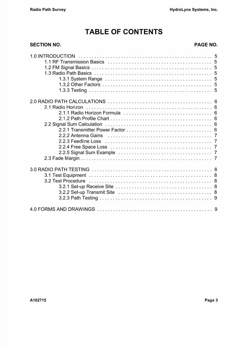
4.0 FORMS AND DRAWINGS
AC100891 Path Profile ChartA101019 Radio Path Verification Checklist

8/7/2019 Radio Path Survey
http://slidepdf.com/reader/full/radio-path-survey 10/12
HydroLynx Systems, Inc. Radio Path Survey
Page 10 A102715

8/7/2019 Radio Path Survey
http://slidepdf.com/reader/full/radio-path-survey 11/12
8/7/2019 Radio Path Survey
http://slidepdf.com/reader/full/radio-path-survey 12/12
HydroLynx Systems, Inc. ! 950 Riverside Pkwy., Suite 10 ! West Sacramento, CA 95605Phone 916-374-1800 ! Fax 916-374-1877 ! Email [email protected]
RADIO PATH VERIFICATION CHECKLIST Document Number A101019
GAUGE #
LOCATION: TEMPERATURE: °
CLOUD COVER: CLEAR G SCATTERED G OVERCAST G
TECHNICIAN: DATE:
TRANSMITTER
TYPE USED: DATA G VOICE G
FREQUENCY: Mhz POWER watts
ANTENNA:
OMNI G
DIRECTIONAL G BEARING:
OTHER G
ANTENNA HEIGHT: FEET FROM GROUND LEVEL
DISTANCE FROM CENTRAL SITE OR REPE ATER:
PERCENTAGE OF DATA RECEIVED: %
RECEIVED AT: G REPEATER #
G CENTRAL SITE
G REMOTE STATION TESTER
NOTES: