Embed Size (px)
Citation preview

Radiation Hardening of LED Luminaires for Accelerator Tunnels
J. D. Devine, and A. FloriduzCERN, Geneva, Switzerland
AbstractThis paper summarises progress made towards the radiation hardening of LEDemergency luminaires for evacuation and emergency response within the un-derground areas of the CERN accelerator complex. The objective has been toradiation harden existing Commercial Off-The-Shelf (COTS) emergency lumi-naires to maximise lighting performance, without compromising IEC 60598-2-22 compliance. A systems level approach has been adopted, leading to thedevelopment of a diode bridge based AC/DC power converter. Modified COTSluminaires including this converter design have been irradiated (to 100 kGyTID using a Cobalt-60 source), with results of a subsequent photometric anal-ysis presented. Following encouraging tests results, a reference design for thepower converter has been released under the CERN Open Hardware License toencourage manufacturer adoption. The paper concludes with areas of interestfor future research in further improving the radiation hardness of LED emer-gency lighting for accelerators with detailed studies at the component level forhigh power white LED devices and associated optical components.
KeywordsRadiation resistant power supply; emergency lighting; particle accelerators.
1 IntroductionCERN has around 45 km of underground tunnels containing particle accelerators, beam transfer linesand access tunnels at depths of up to 100 m below the surface [1]. During accelerator shutdown periodsextensive access is required for human operatives performing maintenance and upgrade activities. Arobust emergency lighting system, comprising in excess of 3000 luminaires, exists to ensure safe evacu-ation from underground areas in the event of an emergency. Currently emergency lighting is provided bylegacy lighting systems dating from the original underground accelerator installations (Super Proton Syn-chrotron and Large Electron Positron Collider) which comprise a mixture of low-pressure sodium andincandescent luminaires. These are now increasingly difficult to maintain due to regulations applicableto lighting systems which limit the supply of replacement lamps, creating the need for the developmentof a replacement system based on current lighting technology and radiation resistant properties.
1.1 Emergency lighting systemsEmergency lighting systems in tunnel accelerators are intended to provide a minimum level of illumi-nation for escape routes, in case of a loss of power to normal luminaires. The purpose of emergencylights is to allow people working in underground areas to escape safely from the tunnels and to facilitatethe intervention of emergency services if required. At CERN, emergency luminaires are supplied fromrechargeable Nickle Metal Hydroxide (NiMh) batteries via 48 V DC to 230 V AC inverters. Luminairesare supplied through fire rated cables, with each underground area typically being served by two sepa-rate electrical circuits to provide redundancy. In most areas of the Large Hadron Collider (LHC) tunnel,the emergency lighting system makes use of low-pressure sodium discharge lamps retained from the eraof the LEP accelerator. Sodium discharge lamps with wire wound inductive ballasts have proved to behighly reliable and radiation resistant throughout the radiation environments created by both the LEP andthe LHC [2], as they are intrinsically highly tolerant to radiation effects.
arX
iv:1
609.
0348
1v1
[ph
ysic
s.ac
c-ph
] 1
2 Se
p 20
16

PSU LED PMMA GLASSPOWER INPUT
LIGHTOUTPUT
Fig. 1: System model of an LED emergency luminaire.
In recent years, Light-Emitting Diodes (LED) technology has become an attractive alternative totraditional incandescent, fluorescent and discharge lamps, not only for the general illumination marketbut also in the field of emergency lighting, thanks to their compact dimensions, instant response and highluminous efficacy. A major role in this transition has been played by national and international regula-tions, such as the EU directive no. 245/2009, which has led to a ban on certain types of inefficient metalhalide, mercury and high-pressure sodium lamps. As a combined consequence of legislative pressureand technological progress, the expansion of the LED market appears inevitable while high intensitydischarge lamps, including low-pressure sodium lights, are losing market share and ultimately becomingobsolete [3]. For this reason, a new generation of LED emergency luminaires is being developed for usein CERN underground facilities.
1.2 Radiation environmentThe LHC radiation environment is characterised in [2], [4] and [5]. Since the emergency luminaires willeventually be installed on the walls of all underground areas (tunnels and caverns) of the CERN accelera-tor complex, they must be radiation hardened to an appropriate level in order to prevent premature failure.Working within the context of the As Low As Reasonably Achievable (ALARA) principle, the systemmust be designed to maximise operational lifetime, in order to prevent interventions related to luminairebreakdown and replacement. For this reason, the desired lifetime of emergency lighting luminaires is aminimum of 5 years.
The latest values (2015) of yearly High Energy Hadrons (HEH) fluence (i.e. fluence of all hadronswith an energy greater than 20 MeV), 1 MeV equivalent neutron (neq) fluence and Total IntegratedDose (TID) in the LHC tunnel and its injectors are presented in [4]; in addition, this report illustratesthat TID values on the tunnel walls are approximately one order of magnitude smaller than close tothe corresponding beam lines, as evidenced by from both direct TID measurements and Monte Carlosimulations. Therefore, a suitable target dose for the emergency luminaires under development can beset to 100 kGy, since this value exceeds the expected TID relative to 5 years irradiation in most of theCERN accelerator complex, meeting the requirement of the desired lifetime.
In underground areas, an LED emergency lighting system may also be interlocked to activateonly during machine stops (i.e. no beam condition), since no access to these areas is possible for humanoperators during accelerator runs.1 Hence, LED emergency luminaires in CERN tunnels and caverns willalso be studied when not powered, at ambient temperature (for reference, typical LHC tunnel temperatureduring physics runs is within the range 17 ± 3C).
1.3 LED luminairesThe block diagram model of a COTS LED emergency luminaire is depicted in Fig. 1. The systemcomprises a number of components, including a Power Supply Unit (PSU), which converts the input
1Due to the long warm-up time of low-pressure sodium lamps, the present emergency luminaires in the CERN acceleratorcomplex are always energised in order to avoid conflict with EN 1838 requirements for the rapid activation of emergencylighting systems. Therefore, adoption of LED lighting provides increased flexibility for energy savings thanks to potential forreduced operational time.
2

supply voltage (typically 230 V 50 Hz AC) to the DC value required by the LEDs supplied. Switch-Mode Power Supply (SMPS) topologies, such as buck, boost and flyback converters, are commonly usedto supply LEDs [6] in COTS luminaires. However, these PSUs are not designed to be radiation hardand when tested show very poor performance, causing almost immediate catastrophic failure of LEDluminaires when subjected to a typical accelerator radiation environment [7]. The reliability required fortheir use in accelerator environments (see, for example, [8] for a review of radiation effects on powerconverters), can therefore not be guaranteed. Each luminaire may contain one or more high power LEDlight sources, each with a lumen output of approximately 100 lm or greater. The effect of radiation onLED light output has been studied extensively for optical power levels up to 100 mW [9], [10], [11]however little published research exists for high power LEDs up to 1 W and beyond. The individualLED is generally equipped with a plastic lens to improve the light output distribution (see Fig. 1); thelens is usually made of PolyMethyl MethAcrylate (PMMA) plastic selected for high light transmission,a property which degrades when exposed to radiation [12]. Depending upon the luminaire design, theLED may also be contained in an IP6X housing protected with glass windows to allow light transmission(see Fig. 1). Borosilicate retains its optical transmission properties relatively well when irradiated [13]and has been specified for installations following the tests described in this paper. However, the overalllight output of the system may be further improved by careful selection of quartz or high purity fusedsilica materials [14] in the future.
Having developed a simple system level model for the LED luminaires, the failure modes of eachcomponent and the corresponding impact on the system performance can be demonstrated (see Table1). Early functional testing on a range of COTS products rapidly indicated that first stage of radiationhardening would be to prevent the catastrophic failure mode of the PSU due to the inclusion of sensitiveSMPS. Following this insight, CERN has worked with two luminaire vendors to modify their standardproducts into radiation hardened versions. The luminaires contain modified PSUs, based on a diodebridge rectifier principle, providing significantly increased radiation hardness, and do not conflict withthe requirements of IEC 60598-2-22.
Table 1: Radiation effects on luminaire components.
Component Effects of radiation
PSU Catastrophic failure modes for SMPS
LEDRadiation damage (displacement) leading to reduced
flux
PMMA (plastic
lens compound)
Free radical formation leading to reduced light
transmission
Degraded mechanical properties
GlassColour centre formation leading to reduced light
transmission
2 Design response2.1 Preliminary irradiation testsPreliminary irradiation tests of two sets of COTS emergency lighting systems have been performedat CNRAD facility [15] at CERN. The goal was to analyse the response to radiation of COTS powersupplies in order to identify a suitable basis for future design of a rad-tolerant PSU for LED lighting.
3

1
L
T
B
B
L L L L L R
L L L L L L R
L L L L L L R
L L L L L L R
Figure 1: Drawings.
0.1 Drawings
(a)
2
T
B
B
6 LEDs String
6 LEDs String
6 LEDs String
6 LEDs String
Figure 2: Drawings.
PWM
O.L.P. Control
O.I.P.
O.V.P.Detection
Circuit
FilterFilterVin VoutFilter
EMI
Figure 3: Drawings.
TB
C L
Figure 4: Drawings.
(b)
Fig. 2: (a) Circuit diagram of the power supply using diode bridge rectifier topology. (b) Block diagram of theSMPS used in COTS luminaires under test.
The first set of luminaires under test comprised three lamps with a simple power supply based on theprinciple of a transformer and a diode bridge rectifier, whose circuit diagram is represented in Fig. 2a.Each luminaire presents a step down transformer (denoted with T on the circuit diagram) supplying twoW08M diode bridge rectifiers (manufactured by MIC Electronics, and denoted withB), each one feedingtwo parallel strings of six series connected low power, low current (<50 mA) white LEDs, indicated asL. Each string is series connected to a 560 Ω resistance in order to prevent thermal runaway of LEDs.The second batch comprised three luminaires using SMPS converters, whose block diagram is depictedin Fig. 2b. As can be seen, the AC input voltage is first rectified and filtered; an EMI filter is used tomitigate the injection of harmonics into the grid. Then, this stage is followed by a high frequency DC/DCconverter composed of an inverter using MOSFET power switches, an high frequency transformer and anAC/DC diode rectifier followed by a filter, to smooth the DC voltage. The power switches of the inverterare controlled via PWM modulation, at a switching frequency of 60 kHz. The control feedback loop isclosed by the measurement/detection system, which sends backs to the control circuitry the DC outputvoltage, using opto-couplers. In order to prevent overloads on the input and output side, an overcurrentprotection system (respectively denoted as O.L.P. and O.I.P. on the input and output side) is embedded
4

(a) (b)
Fig. 3: (a) Layout of luminaires during preliminary irradiation tests at CNRAD (CERN); on the left, three lumi-naires using SMPS, on the right three luminaires with diode bridge rectifiers. (b) Picture from remote camera after5 hours of irradiation; the three luminaires using diode bridges are on the right, luminaires with SMPS on the left.
into the control system; moreover, and Over Voltage Protection (O.V.P.) on the DC output side is alsopresent.
The irradiation took place into four steps, with cumulative TID of 9, 47.9, 93.7 and 129.3 Gy. Thefour irradiation steps lasted respectively 230, 900, 1260 and 1095 hours, separated by intervals with noirradiation of 109, 75 and 105 hours. The irradiation conditions are summarized in Table 2. The sixluminaires were installed on a test bench (illustrated in Fig. 3a), located in CNRAD test area, with adeported RadMon [16] positioned in the middle of the rack, at about 60 cm from ground, to measureprecisely the radiation level of the devices under test. All luminaires were powered while irradiated(active test) and were monitored through a remote rad-hard camera.
Table 2: Irradiation condition of the COTS luminaires.
Step 1 Step 2 Step 3 Step 4 Total
TID (Gy) 9 38.9 45.8 35.6 129.3
1 Mev neq fluence(1011 · cm−2
)0.7 3.0 3.6 2.7 10.0
HEH fluence(1011 · cm−2
)0.5 2.1 2.5 1.9 7.0
Duration (h) 230 900 1260 1095 3485
Time after previous step (h) / 109 75 105 /
The three luminaires using SMPS units failed just after the start of the test, after 1 hour, 4 hours and18 hours of irradiation, corresponding to TID values of less than 0.1 Gy, 0.1 Gy and 0.4 Gy respectively.These results are summarized in Table 3. Figure 3b shows the test bench from the remote camera after5 hours of irradiation, with two of the luminaires using SMPS already failed. The failure of SMPSluminaires can be ascribed to displacement damage effects on the power switches of the high frequencyDC/DC converter, on the PWM control circuitry and on opto-couplers.
Luminaires using power supplies with diode bridge rectifiers succeeded in completing the irradi-
5

Table 3: Irradiation of luminaires with SMPS.
Characteristics Luminaire 1 Luminaire 2 Luminaire 3
Time before failure (h) 1 4 18
TID reached (Gy) < 0.1 0.1 0.4
HEH fluence(cm−2
)< 5.4 · 108 5.4 · 108 2.2 · 109
1 MeV neq fluence(cm−2
)< 7.3 · 108 7.3 · 108 2.9 · 109
ation test, working for the full duration without showing any significant degradation in illuminance, asconfirmed by visual inspections and luxmeter measurements performed after the end of the irradiation.The total dose reached was of 129 Gy, at a HEH fluence of 7.0 · 1011 cm−2 and 1 MeV neq fluence of1.0 · 1012 cm−2.
The irradiation test identified the power supply as the most critical component in COTS emer-gency luminaires and confirmed that converters using diode bridge topology offer an higher reliabilityin radiation environment than SMPS. Following these preliminary results, a prototype of a rad-tolerantPSU using the bridge rectifier topology has been built; this converter includes a GBU8K diode bridge,samples of which have been previously tested for radiation hardness by the LHCb experiment [17], upto 1 MeV neq fluence of 4.8 · 1013 cm−2, corresponding to a TID of 3.3 kGy; GBU8K bridge rectifiermakes use of glass passivated junctions. The circuit diagram of the prototype power supply is shownin Fig. 4a; it includes a 230:6 step-down transformer (denoted with Tp in Fig. 4a) and an electrolytic220 µF capacitor (denoted with Cp). The power supply feeds a single Cree XR-E LED, indicated withLp, producing white light; Cree XR-E LED is in turn composed of a blue InGaN LED and yellow phos-phors. A picture of an assembled prototype is shown in Fig. 4b. 2 PSU prototypes have been tested inCNRAD facility, in a test position which allowed higher TID and fluences than the location of the pre-vious test of COTS luminaires. Irradiation took place in four steps with cumulated TID of 160.2, 406.1,760.1 and 1107.6 Gy, with final cumulated HEH fluence of 1.1 · 1013 cm−2 and cumulated 1 MeV neqfluence of 7.7 · 1012 cm−2. From a comparison with the values presented in [4], the TID reached duringthis irradiation test corresponds approximately to the dose accumulated on the LHC tunnel walls after 5years exposure. All the PSUs were powered while irradiated (active test). Inspections were performedafter the last irradiation step, and confirmed that all PSUs were still working. Following this encouragingresult, the prototype has been chosen as the basis for a rad-tolerant PSU for LED lighting.
1
0.1 Drawings
Tp B
Cp Lp
(a) (b)
Fig. 4: (a) Circuit diagram of the prototype power supply using GBU8K diode bridge rectifier. (b) Picture of theprototype PSU assembled on a stripboard.
6

Table 4: Irradiation condition of the prototype PSU.
Step 1 Step 2 Step 3 Step 4 Total
TID (Gy) 160.2 245.9 354 347.5 1107.6
1 Mev neq fluence(1012 · cm−2
)1.6 2.4 3.5 3.4 11
HEH fluence(1012 · cm−2
)1.1 1.7 2.5 2.4 7.7
2.2 Power Supply ModificationsOnce a suitable power converter topology had been identified, work with luminaire vendors was com-menced in order to incorporate the new power converter topology into standard products with opticalcharacteristics suitable for emergency evacuation lighting within underground tunnels. A second vendorwith an alternative luminaire design more suited to underground caverns and larger spaces was also ap-proached. The power converter specification was issued to both vendors, which included the same bridgediode rectifier (GBU8K) used in the prototype PSU presented in Section 2.1. As a result of these initia-tives, two types of radiation hardened emergency luminaire were produced for further radiation testing.The circuit diagrams of Vendor 1 and Vendor 2 power supplies are shown respectively in Fig. 5a andFig. 5b. The values of the components are listed in Table 5.
2.3 Components under testThe luminaires from Vendor 1 utilise three Cree XP-G LEDs as light sources, with a combination ofPMMA lenses and glass windows. Vendor 2 uses a single Cree XR-E LED with a PMMA lens todirect the light output. Cree XR-E and XP-G LEDs produce white light; they are composed of blueLEDs (InGaN epitaxial layer on silicon substrate) with phosphors producing yellow light. To the best ofour knowledge, no previous irradiation tests of Cree XR-E and XP-G LEDs have been reported. Bothluminaires use the GBU8K diode manufactured by Vishay. Further components include surface mountedmulti-layer ceramic capacitors and metal-film resistors.
1
0.1 Drawings
T2B
C
L2
R2
T1B
C
L1
R1
L1
L1
(a)
1
0.1 Drawings
T2B
C
L2
R2
T1B
C
L1
R1
L1
L1
(b)
Fig. 5: (a) Circuit diagram of Vendor 1 power supply. (b) Circuit diagram of Vendor 2 power supply.
7
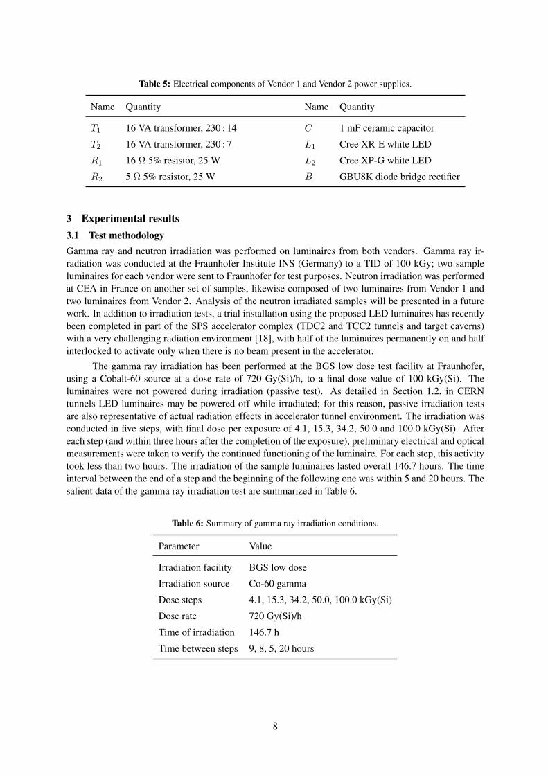
Table 5: Electrical components of Vendor 1 and Vendor 2 power supplies.
Name Quantity Name Quantity
T1 16 VA transformer, 230 : 14 C 1 mF ceramic capacitor
T2 16 VA transformer, 230 : 7 L1 Cree XR-E white LED
R1 16 Ω 5% resistor, 25 W L2 Cree XP-G white LED
R2 5 Ω 5% resistor, 25 W B GBU8K diode bridge rectifier
3 Experimental results3.1 Test methodologyGamma ray and neutron irradiation was performed on luminaires from both vendors. Gamma ray ir-radiation was conducted at the Fraunhofer Institute INS (Germany) to a TID of 100 kGy; two sampleluminaires for each vendor were sent to Fraunhofer for test purposes. Neutron irradiation was performedat CEA in France on another set of samples, likewise composed of two luminaires from Vendor 1 andtwo luminaires from Vendor 2. Analysis of the neutron irradiated samples will be presented in a futurework. In addition to irradiation tests, a trial installation using the proposed LED luminaires has recentlybeen completed in part of the SPS accelerator complex (TDC2 and TCC2 tunnels and target caverns)with a very challenging radiation environment [18], with half of the luminaires permanently on and halfinterlocked to activate only when there is no beam present in the accelerator.
The gamma ray irradiation has been performed at the BGS low dose test facility at Fraunhofer,using a Cobalt-60 source at a dose rate of 720 Gy(Si)/h, to a final dose value of 100 kGy(Si). Theluminaires were not powered during irradiation (passive test). As detailed in Section 1.2, in CERNtunnels LED luminaires may be powered off while irradiated; for this reason, passive irradiation testsare also representative of actual radiation effects in accelerator tunnel environment. The irradiation wasconducted in five steps, with final dose per exposure of 4.1, 15.3, 34.2, 50.0 and 100.0 kGy(Si). Aftereach step (and within three hours after the completion of the exposure), preliminary electrical and opticalmeasurements were taken to verify the continued functioning of the luminaire. For each step, this activitytook less than two hours. The irradiation of the sample luminaires lasted overall 146.7 hours. The timeinterval between the end of a step and the beginning of the following one was within 5 and 20 hours. Thesalient data of the gamma ray irradiation test are summarized in Table 6.
Table 6: Summary of gamma ray irradiation conditions.
Parameter Value
Irradiation facility BGS low dose
Irradiation source Co-60 gamma
Dose steps 4.1, 15.3, 34.2, 50.0, 100.0 kGy(Si)
Dose rate 720 Gy(Si)/h
Time of irradiation 146.7 h
Time between steps 9, 8, 5, 20 hours
8

3.2 Results from goniophotometer analysisFollowing the gamma irradiation exposure, the luminaires were sent for a Type C Moving Mirror gonio-photometer analysis at TSI-LUX Ltd. in the UK. Electrical and photometric measurements have beenperformed and the results are collected in Table 7.
Table 7: Summary of electrical and photometric measurements.
Quantity Vendor 1 Vendor 2
Frequency 50 Hz 50 Hz
Voltage 230.06 V 230.04 V
Current 0.031 A 0.031 A
Power 6.50 W 6.20 W
Power factor 0.924 0.879
Apparent power 7.04 VA 7.09 VA
CRI (Ra) 71 65
Luminous flux pre-irradiation 900 lm 209 lm
Luminous flux post-irradiation 177 lm 55 lm
Variation in luminous flux -80.33% -73.68%
Luminous efficacy pre-irradiation 128.57 lm/W 32.15 lm/W
Luminous efficacy post-irradiation 27.23 lm/W 8.87 lm/W
Variation in luminous efficacy -78.82% -72.41%
3.3 Analysis of resultsFrom a comparison of the luminous flux before and after irradiation, an overall reduction of 80.3% hasbeen observed for Vendor 1 luminaires. This reduction appears to be predominantly due to the glass,which became dark just after the 4.1 kGy exposure (see Fig. 6a), and the PMMA lenses of the LEDs,which turned yellow. Figure 6b shows the luminaire switched on, emitting a yellowish light, after adose of 50 kGy. Finally, Figures 7a-7e show Vendor 1 luminaires after every irradiation step. As for
(a) (b)
Fig. 6: (a) Detail of Vendor 1 luminaire glasses after 4.1 kGy irradiation. (b) Vendor 1 luminaire on, after 50 kGyirradiation.
9

Vendor 2 product, the drop in the luminous flux is slightly lower than Vendor 1, thanks to the absence ofthe glass, and can be ascribed to the degradation in the PMMA which started to become yellow after adose of 15 kGy. Figures 8a-8e illustrate Vendor 2 luminaires after every irradiation step. The variationsin luminous efficacy are close to those in luminous flux for both products, meaning that no significantvariation in input power (due to LEDs and diodes degradation) has been observed.
The data from the photometric measurement has been integrated into a DIALux model for a light-ing simulation of a typical segment of the LHC tunnel. Fixing centres of the luminaires are designed toaccount for the reduction in luminous flux due to radiation. In the simulation, Vendor 1 luminaires areplaced on the tunnel wall at fixing centres of 14 m, while Vendor 2 luminaires are positioned on the ceil-ing of the tunnel at 10 m fixing centres. The simulation results of Vendor 1 product are summarized inTable 8 and a 3D rendering in false colour is shown in Fig. 9a. We recall that EN 1838 standard requiresa minimum of 0.5 lx for anti-panic lighting and 1 lx for escape routes (at centre line). For this reason, theplastic and glass types for future luminaires will be carefully selected to improve optical transmissionwhen irradiated. The same analysis has been performed for Vendor 2 luminaire, and results are shownin Table 8 and Fig. 9b. Figure 9c illustrates the natural visual impression of the tunnel segment usingluminaires of both vendors after 100 kGy irradiation.
Table 8: DIALux simulations of Vendor 1 and Vendor 2 luminaires in LHC tunnel.
QuantityVendor 1 Vendor 2
Before After Before After
Average over the whole surface 9.78 lx 2.01 lx 3.46 lx 1.60 lx
Maximum value over the whole surface 17.0 lx 9.45 lx 6.01 lx 2.78 lx
Minimum value along the escape route 5.67 lx 0.65 lx 1.85 lx 0.92 lx
Minimum value at center line along escape route 7.48 lx 1.22 lx 2.02 lx 1.02 lx
4 Future developmentsThe need for a new PSU as the first stage in radiation hardening COTS luminaires, together with im-pending obsolescence of the GBU8K rectifier, has spurred the production of a reference design, releasedunder the CERN Open Hardware License [19]. Future tests up to 100 kGy are planned for the new PSUin CHARM facility at CERN [20] using mixed field radiation produced from 24 GeV protons, investi-gating also the effect of different load conditions. Dedicated irradiation tests for the power LEDs arescheduled at IRRAD facility at CERN [21], so as to identify the impact of displacement damage using24 GeV protons, under different bias conditions. Likewise, gamma ray irradiation tests for samples ofoptical components (PMMA lenses and borosilicate windows) are planned. Future studies will addressthe analysis of photometric data from the neutron irradiated sample luminaires, which will provide astronger indication on the effect of displacement damage to the LEDs, and the consequent impact onoverall system performance. For the purposes of this paper, the effects of annealing within the LED diehave been ignored due to a significant delay between irradiation and photometric measurement, howeverthe impact of this phenomena would also be an interesting subject for future study, within the context ofthe duty cycle for the luminaires and operational practices of particle accelerators.
5 ConclusionsIn this paper, we presented progress towards radiation hardening of LED emergency luminaires for use inaccelerators environments. After the identification of the PSU as the cause of early catastrophic failuresin COTS luminaires, we described a simple AC/DC power supply for LED emergency luminaires, the
10

(a) (b)
(c) (d)
(e)
Fig. 7: Comparison between irradiated and non-irradiated Vendor 1 luminaires after exposure to: (a) 4.1 kGy, (b)15.3 kGy, (c) 34.2 kGy, (d) 50 kGy, (e) 100 kGy. In Figure (b) both irradiated luminaires are shown.
11

(a) (b)
(c) (d)
(e)
Fig. 8: Comparison between an irradiated (white) and non-irradiated (orange) Vendor 2 luminaire after exposureto: (a) 4.1 kGy, (b) 15.3 kGy, (c) 34.2 kGy, (d) 50 kGy, (e) 100 kGy.
12

(a)
(b)
(c)
Fig. 9: (a) 3D rendering of the DIALux simulation with Vendor 1 luminaires, before (left) and after (right) 100 kGyexposure. (b) 3D rendering of the DIALux simulation with Vendor 2 luminaires, before (left) and after (right)100 kGy exposure. (c) Natural visual impression using Vendor 1 (left) and Vendor 2 (right) luminaires after100 kGy exposure.
inclusion of which allows modified COTS luminaires to remain functional up to a dose of 100 kGy.The proposed luminaires are now being installed within limited areas of the CERN accelerator complex.Future TID tests are planned in order to bound the lifetime of the whole LED luminaire; moreover,detailed study of the principal optical components, (power LEDs, plastic lenses and glass) are scheduled.Future studies identified include active and non-active irradiation tests of the reference PSU design up to100 kGy.
13
AcknowledgmentsThe authors would like to thank Jean-Marie Foray for commencing the LED luminaire testing programmeduring his time at CERN from 2009-2014.
References[1] J. P. Saraiva and M. Brugger, “Radiation levels at CERN’s injectors and their impact on electronic
equipment,” in Proceedings of the 11th International Topical Meeting on Nuclear Applications ofAccelerators, (Bruges, Belgium), pp. 5–8, August 2013.
[2] K. Røed, M. Brugger, D. Kramer, P. Peronnard, C. Pignard, G. Spiezia, and A. Thornton, “Methodfor measuring mixed field radiation levels relevant for SEEs at the LHC,” IEEE Transactions onNuclear Science, vol. 59, no. 4, pp. 1040–1047, 2012.
[3] A. De Almeida, B. Santos, B. Paolo, and M. Quicheron, “Solid state lighting review–potential andchallenges in Europe,” Renewable and Sustainable Energy Reviews, vol. 34, pp. 30–48, 2014.
[4] J. P. De Carvalho Saraiva and M. Brugger, “Radiation Environments and their Impact at the CERN’sInjector Chain,” Dec. 2015. CERN-ACC-NOTE-2015-0042, available at https://cds.cern.ch/record/2114889.
[5] R2E, “Radiation to electronics study group (R2E) homepage,” 2016. Available at http://r2e.web.cern.ch/R2E/.
[6] M. Rico-Secades, A. J. Calleja, J. Ribas, E. L. Corominas, J. M. Alonso, J. Cardesín, and J. García-García, “Evaluation of a low-cost permanent emergency lighting system based on high-efficiencyLEDs,” IEEE Transactions on Industry Applications, vol. 41, no. 5, pp. 1386–1390, 2005.
[7] P. Adell, R. Schrimpf, B. Choi, W. Holman, J. Attwood, C. Cirba, and K. Galloway, “Total-doseand single-event effects in switching DC/DC power converters,” IEEE Transactions on NuclearScience, vol. 49, no. 6, pp. 3217–3221, 2002.
[8] P. Adell and L. Z. Scheick, “Radiation effects in power systems: a review,” IEEE Transactions onNuclear Science, vol. 60, no. 3, pp. 1929–1952, 2013.
[9] A. H. Johnston, “Radiation effects in optoelectronic devices,” IEEE Transactions on Nuclear Sci-ence, vol. 60, no. 3, pp. 2054–2073, 2013.
[10] J. Jimenez, M. Alvarez, R. Tamayo, J. Oter, J. Dominguez, I. Arruego, J. Sanchez-Paramo, andH. Guerrero, “Proton radiation effects in high power LEDs and IREDs for optical wireless linksfor intra-satellite communications (OWLS),” in IEEE Radiation Effects Data Workshop, pp. 77–84,IEEE, 2006.
[11] S. Pearton, F. Ren, E. Patrick, M. Law, and A. Y. Polyakov, “Review–ionizing radiation damageeffects on GaN devices,” ECS Journal of Solid State Science and Technology, vol. 5, no. 2, pp. Q35–Q60, 2016.
[12] K. Toh, K. Sakasi, T. Nakamura, K. Soyama, and T. Shikama, “Effects of neutrons and gamma-rayson polymethylmethacrylate plastic optical fiber,” Journal of Nuclear Materials, vol. 417, no. 1–3,pp. 814–817, 2011.
[13] A. N. Baydogan, “The effect of neutron and mixed gamma and neutron irradiation on the solarproperties of borosilicate glass,” Research on Chemical Intermediates, vol. 40, no. 1, pp. 299–306,2014.
[14] D. Doyle, “Radiation hardness of optical materials,” in 3rd Europa Jupiter System Mission In-strument Workshop, ESA-ESTEC, Optics Section, 2010. Available at http://sci.esa.int/science-e/www/object/doc.cfm?fobjectid=46396.
[15] CNRAD, “Radiation Working Group (RadWG) CNRAD homepage,” 2016. Available at https://radwg.web.cern.ch/RadWG/Pages/CNRAD/cnrad_frame.htm.
14

[16] A. Masi, G. Spiezia, P. Peronnard, M. Donze, M. Brugger, and R. Losito, “The new generation ofLHC accelerator radiation monitoring system,” in Proceedings of the 18th IEEE-NPSS Real TimeConference (RT), pp. 1–7, IEEE, 2012.
[17] T. Bager, J. Casas, B. Palan, and M. Rodriguez, “Validation of switching power supplies, diodebridges, and conditioners for pressure sensors,” EDMS document 1226409, CERN, 2002. Availableat https://edms.cern.ch/document/1226409/1.
[18] C. C. Strabel, H. Vincke, and H. Vincke, “Radiation protection studies for the SHiP facility,” Apr2015. Available at: https://cds.cern.ch/record/2063301.
[19] J. D. Devine, “Radiation tolerant LED PSU,” 2016. Available at http://www.ohwr.org/projects/radtol-led-psu.
[20] J. Mekki, M. Brugger, R. G. Alia, A. Thornton, N. C. D. S. Mota, and S. Danzeca, “A mixed fieldfacility at CERN for radiation test: CHARM,” in Proceedings of the 15th European Conference onRadiation and Its Effects on Components and Systems (RADECS), pp. 1–4, Sept 2015.
[21] F. Ravotti, M. Glaser, and M. Moll, “Upgrade scenarios for irradiation lines: Upgrade of the ProtonIrradiation Facility in the CERN PS EAST AREA,” Sep 2014. Available at: http://cds.cern.ch/record/1951308.
15