Embed Size (px)
Citation preview

JOURNAL OF THE OPTICAL SOCIETY OF AMERICA
Radiant Emission Characteristics of Diffuse Conical Cavities
E. M. SPARRoW AD V. K. JONSSONHeat Transfer Laboratory, Departmzent of Mechanical Engineering, University of Minnesota, Minneapolis, Minnesota
(Received 10 September 1962)
The radiant interchange within a diffuse conical cavity has been formulated without approximation forboth cases of prescribed wall temperature and prescribed wall heat flux. Highly accurate numerical solutionshave been obtained for a wide range of cone opening angles and surface emissivities. Results are presentedfor the radiant efflux from the cavity as a whole and also for the distributions along the cavity surface ofsuch quantities as the apparent radiant emittance, local heat flux (for prescribed surface temperature), andtemperature (for prescribed heat flux). A comparison with the approximate analysis of Gouffe disclosedlarge errors in this prior work.
INTRODUCTION
THE radiant emission of cavities has been a subjectT of common interest to investigators of illumina-tion and of radiative heat transfer. This interest stemsfrom the fact that a cavity may serve as a source ofradiant energy having considerably higher emissivepower than a plane surface. This property is sometimesreferred to as the cavity effect and is related to themultiple reflections which are sustained by rays beforethey stream out of the cavity.
A useful survey of analytical work on cavity-typesources of radiant energy has been presented in Ref. 1.In discussing the various investigations, care was takento bring out the approximations which were made ineach; and it was indicated that certain approximationswere of doubtful validity. Meanwhile, in theheat-transferliterature, various studies of the emission characteristicsof diffusely emitting and reflecting cavities have beencarried out without approximation. Results have beenpresented for the circular cylinder, the sphere, and theparallel-walled groove. A new formulation for radiantinterchange within a diffusely emitting but specularlyreflecting cylinder has been devised, 3 but this has yetto be applied to a finite-length cavity.
An important cavity configuration for which thereexists neither a correct formulation nor reliable numeri-cal results is the diffuse conical cavity. It is the aim ofthis report to treat the diffuse conical cavity withoutapproximation. An exact, systematic formulation ispresented and from this there are obtained numericalresults for both the over-all and local radiant energytransfers. The over-all results correspond to the radiantenergy flux streaming out of the cavity as a whole,while the local results relate to the radiant energyfluxes which leave various surface locations within thecavity. This information is provided for a wide rangeof cone opening angles and radiation properties of thecavity surface. The analysis and results include bothcases of uniform surface temperature and uniformsurface heat flux. Within the knowledge of the authors,
I C. S. Williams, J. Opt. Soc. Am. 51, 566 (1961).2,E. M. Sparrow, L. U. Albers, E. R. G. Eckert, V. K. Jonsson,
and J. L. Gregg, J. Heat Transfer C84, 73, 188, 270 (1962).3 K. S. Krishnan, Proc. Roy. Soc. (London) A257, 302 (1960).
the latter of these boundary conditions has not pre-viously been considered in cavity studies. The onlyprior work known to the authors4' 5 on the diffuse conicalcavity is due to Gouffe.6 As discussed in Ref. 1, Gouffetreated the cone, among other configurations, withinthe framework of a highly approximate theory. Resultsof uncertain accuracy were reported for the effectiveemissivity of the cavity (i.e., over-all energy fluxstreaming from the cavity). These results will becompared later with those of the present analysis, andsubstantial errors will be demonstrated. Gouffe'smethod did not provide any information on the distri-bution of the radiant flux along the walls of the cavity.
dAC at x=(
L XdA,FIG. 1. Schematic of a
conical cavity.
A schematic diagram of the cavity under study isshown in Fig. 1. The cone opening angle is , while L isthe slant height of the cavity. The coordinate x measuresdistances along the surface from the apex. In theanalysis that follows, the cavity surface is assumed toemit and reflect diffusely, i.e., Lambert's cosine law isobeyed.
ANALYSIS
The first step in the analysis is to write a radiantflux balance for a typical surface element on the wallof the cavity. For this purpose it is convenient toselect a ring-shaped area dA, as shown in Fig. 1. Ifenergy conservation is to be satisfied, the radiant fluxstreaming away from the area element must equal thesum of the emitted energy plus the reflected portion ofthe incident energy. The radiant energy leaving an
4 During the review by the papers committee, unpublishedanalytical work by Page (Ref. 5) on the cone problem was broughtto the attention of the authors, who wish to acknowledge it here.
I C. H. Page, National Bureau of Standards (private communi-cation, 1963).
6 A. Gouffe, Rev. Opt. Nos. 1-3 (1945).
816
VOLUME 53, NUMBER 7 JULY 1963

DIFFUSE CONICAL CAVITIES
element per unit time and area has been variouslycalled the apparent radiant emittance, the radiosity,the brightness, or the total emission. It is denoted hereby the symbol B. The incident energy per unit timeand area, the irradiance, is denoted by I. Then, fromenergy conservation
B(x) = e T4(x)+pI(x),
Uniform Wall Temperature
When the surface of the cavity is at uniform tem-perature, T(x) is replaced by T (a constant), andEq. (4) is rewritten as
L
'E.(x) = + (1-,E) Ea.Q)dFQx~0~
(5)(1)
in which the possible dependence of B, T and I on xis indicated explicitly, and e and p, respectively,represent the emissivity and reflectivity.
The next step is to eliminate the irradiance I fromEq. (1). This may be done by taking cognizance of thefact that radiant energy arriving at dA . must comefrom other surface locations on the cavity wall.7 Forinstance, consider the radiation leaving some othersurface location x= t (see Fig. 1). An amount B(S)dA
leaves dA in all directions. Of this a quantity[B()dA~]dF~_ arrives at dAx, where dF~_ is ageometrical factor' for diffuse interchange betweensurface elements dAt and dA x. Utilizing the reciprocitytheorem for diffuse geometrical factors, which states(Ref. 9, p. 9)
dAtdF~_= dA OdF, (2)
it follows that the radiant energy leaving dAs andarriving at dA is B(t)dF,dA ,; or, per unit area atdA , this is B(t)dFZ. But, energy arrives at x from alllocations 0< t< L, and the total is found by integration:
L
I(x)= = BQ()dFt.0~
(3)
Introducing this into the radiant flux balance (1),there follows
rL
B (x) = eoT4(x)+pJ BQ()dFQ. (4)
In general, the reflectivity p =l-a for an opaquesurface, in which a is the absorptivity. Further, for agray surface, a = e and p 1- e. The graybody postulatewill be employed in the subsequent analysis.
Inspection of Eq. (4) reveals that the unknownbrightness distribution B appears under the integralsign as well as in other parts of the equation. Therefore,Eq. (4) is an integral equation. The B (x) and B (t) are
the same functions; only the names of the independentvariables have been interchanged. To proceed with a
solution of Eq. (4), it remains to provide the thermalboundary conditions and to derive the angle factordFt.
7 Energy entering the cavity from outside is generally notincluded in studies of the emission characteristics of cavities.
8 The geometrical factor represents the fraction of the radiantenergy leaving one surface element which arrives at anothersurface element.
9 M. Jakob, Heat Transfer (John Wiley & Sons, Inc., NewYork, 1957), Vol. 2.
in which Ea is a ratio of the apparent radiant emittanceto the blackbody emissive power, i.e.,
ea(x)= B(x)/oTw4. (6)
Ea may be logically regarded as the local apparentemissivity. Since the integral appearing on the right-hand side of Eq. (5) is always positive, it follows thatea is always greater than e.
For problems in illumination or in pyrometry, thelocal apparent emissivity is itself of substantial interest.Additionally of interest are the heat-transfer charac-teristics of the cavity. The net local rate of heat transferper unit area, denoted by q, is the difference betweenthe radiant flux emitted at a surface location and thatwhich is absorbed,
q (x) = ea-T4(x) -aI(x).
Utilizing Eq. (1), this becomes
q (x) = [e/(-e)][aT 4 (x)- B(x)];
and, for the case of uniform wall temperature,
q( () er B( )l -= r 1- x=-[1-,C Wl
aTw4 1-E Tw 4 -,e
(7a)
(7b)
(8)
Thus, it is seen that the local heat flux q(x) and theapparent radiant emittance B(x) (or the apparentemissivity Ea) are essentially interchangeable quantities.
The rate Q at which radiant energy streams outwardthrough the cavity opening is found by integrating thelocal heat flux q over the area of the cavity wall.
or
rL
Q= f q(x)2 7rx sin (0/2)dx,
Q 2 r'q(x)x /x\_ - I -d ,
o-T 4Ao sin(0/2) Jo a-Tw4L L
(9)
in which A is the area of the cavity openingAo=7rl2 sin2(0/2). As written, the second member ofEq. (9) compares the radiant flux Q which passesthrough the cavity opening with that from a blackbodystretched across the opening. This represents thehemispherical emissivity of the cavity as a whole. Ifthere were no cavity, Q/aTw4Ao would equal e. Due tothe presence of the cavity, this ratio will exceed e.Therefore, the deviation from e of Q/o-Tw4Ao providesa measure of the cavity effect.
817July 1963

E. M. SPARROW AND V. K. JONSSON
It is easily seen that the results for B(x) or e(x),q(x), and Q all depend upon the solution of the integralequation (5). These solutions and the correspondingresults are discussed later.
Uniform Wall Heat Flux
When the wall heat flux is prescribed, the quantitiesof practical interest which remain to be determined arethe apparent radiant emittance B(x) and the tempera-ture distribution T(x) along the cavity surface. Forthe case of uniform wall heat flux, q(x) is replaced byqw (a constant) and Eq. (7b) is solved for T 4 (x);
-T 4(x)= [(1-E)/e qw+B(x). (10)
Eliminating aT4 (x) between Eqs. (10) and (4), thereis obtained
L B:(X)= + 0(t)dFZ; 3= - (I11)
0~o qw
The foregoing is an integral equation of the samegeneral type as has already been encountered in Eq.(5). However, there is an interesting difference indetail; namely, that the surface emissivity e, whichappears as a parameter in Eq. (5), is absent in Eq. (11).
Clearly, once solutions of Eq. (11) have been found,then both the apparent radiant emittance and the
surface temperature distributions will be known. Thesesolutions and results are given in a later section.
Geometrical Factor Derivation
A necessary ingredient for the foregoing analysisis the geometrical factor for diffuse interchange betweentwo ring-shaped area elements respectively located atpositions x=x and x= t on the cavity wall (see Fig. 1).The derivation of this geometrical factor'0 - 2 facilitatedby first considering the interchange between twocoaxial, parallel circular disks of radii r and 2 whichare separated by a distance h. The angle factor fordisk-to-disk interchange, Fd-d, which gives the fractionof the radiant energy leaving Disk 1 which arrivesat Disk 2 is (Ref. 9, p. 14)
Fd-d= {h2 +rl2+r 22-[(h2+r,2+ r22)2
-4r, 2r2 2]1}/2r, 2 . (12)
Now, let the disks share a common axis with the conicalcavity, and let Disk 1 be stretched across the cavityat location x= t and Disk 2 be stretched across thecavity at location x = x. Then,
ri= sin(0/2), r2= x sin(0/2),
With these, Eq. (12) becomes
h= I- xlcos(0/2).
x2+V-2xt cos2 (0/2)- I t-xl [(X+ t)2-4xt cos2(0/2)]1
242 sin2 (0/2)
Also, consider the interchange between a disk locatedat x= t and another disk located at x=x+dx.The appropriate disk-to-disk geometrical factorFdd(, x+dx) is identical to Eq. (13), with x replacedby x+dx.
Suppose for concreteness that >x. From physicalreasoning, it is easy to see that energy leaving thedisk at and passing through a transparent disk atx+dx must either strike a disk at x or else be incidenton a ring element of length dx (area dA ) on the surfaceof the cone, therefore
Fd-d , x+dx) = Fd-d ,x)+dFd.,( ,x), (14)
where the subscript d-r indicates interchange betweendisk and ring. After rearranging Eq. (14), there isobtained
dFdr(Q,X) = (aFd-d/Ox)dx. (15)
Alternatively, by the reciprocity theorem, the geo-metrical factor from a ring at x to a disk at is
Frd(xt)= [2 sin (0/2)/2x] (OFd-d/Ox). (16)
Also, the geometrical factor for interchange between
a ring at x and a disk at +dS Fd(X, +dS), isidentical to Eq. (16) with replaced by +di.
It is further evident that radiant energy leavinga ring at x and passing through a transparent disk at must either strike a disk at +dS or else be incidenton a ring element of length d (area dA ) on the surfaceof the cone, thus
Frd(x,)=Frd(X, +dS)+dF,,(x,), (17)
where the subscript r-r denotes ring-to-ring inter-change. But, dFrr(Xt is precisely the geometricalfactor dF-t which has appeared in the integral equa-tions (5) and (11), and so
OFrd sin(0/2) OFdd]dF~= - -dI= - dj42 dxd.
a~~ 2x Oa ax (18)
The desired geometrical factor is obtained by a doubledifferentiation of the disk-to-disk relation (13), withproper cognizance given to the absolute magnitude
'0 This method of analysis has been employed in Refs. 11 and 12.11 A. C. Bartlett, Phil. Mag. Suppl. 6, 40, 111 (1920).12 H. Buckley, Phil. Mag. Suppl. 7, 4, 753 (1927).
Fd-d , X) = (13)
818 Vol. 53

DIFFUSE CONICAL CAVITIES 819
sign. From this, there results after rearrangement
cos2 (0/2)
2x sin (0/2)
X 11 t-xl (t x)2+6x sin2(0/2)E (t-X)2+ 4x sin2 (0/2) I A
Inspection of the foregoing reveals that the cone openingangle 0 appears as a parameter in the geometrical factorexpression. Correspondingly, the solutions of theintegral equations (5) and (11) will also depend uponparametric values of 0. It is interesting to observe thatwhen 0 - 0 Eq. (19) reduces to the geometrical factorbetween two ring elements on the surface of a circularcylinder. In the limit when 0 * 0, x sin(0/2) -> r and sin(0/2) -- >r, where r is the radius of the cylinder.
With the geometrical factor thus derived, solutionsof the governing equations can now be discussed.
Solutions
A detailed study of the governing integral equations(5) and (11) and the geometrical factor expression (19)reveals that closed-form, analytical solutions are notpossible. However, with the aid of modern electroniccomputing equipment, it is possible to obtain highlyaccurate numerical solutions. In the case of Eq. (5)it is necessary to specify two parameters, the angle 0and the emissivity e, for each solution; while for Eq.(11), the angle 0 is the only parameter.
The numerical solutions were carried out by aniterative procedure. Considering Eq. (5), the first stepwas to specify the values of 0 and . Then, a trialdistribution for a(t) was proposed. For a fixed value ofx, the integration in which appears on the right sideof Eq. (5) could be carried out numerically. Thisyielded a value of Ea corresponding to the fixed x value.Then, another value of x was selected, the integrationrepeated, and an Ea corresponding to the second x valueobtained. By applying this procedure at every meshpoint x in the range <x<L a new Ea distribution wasgenerated. This -new a distribution was then used asinput to the right side of Eq. (5) and the aforementionedoperations repeated. This was continued until con-vergence was achieved.
The numerical integrations were performed usingSimpson's rule. In carrying out the integration, it wasnecessary to take cognizance of the fact that thegeometrical factor has a discontinuous slope at x= ;note the absolute magnitude signs in Eq. (19). Accurateresults cannot be obtained by numerically integratingacross such a discontinuity. Rather, the integration hasto be performed separately on each side of the dis-continuity (i.e., from x=0 to x= and then from x= to x = L). This causes some complication, since theconventional Simpson's rule can only be applied to an
odd number of points, while the separate integrationsnoted above would sometimes have to be extendedover an even number of points. This difficulty wascircumvented and accuracy simultaneously improvedby interpolating between the unknown values of Ea.
Quadratic interpolation was used which has the sametruncation error as the Simpson's rule integration. Thestep size for the integration was selected so that therewould be 51 unknown values of Ea in the range0<x/L< 1; however, the integrations were extendedover 101 points because of the interpolation noted above.Thus, a very small step size was used and, consequently,the results are believed to be highly accurate.
Similar remarks apply to the solution of Eq. (11).
RESULTS
Uniform Wall Temperature
The governing equation (5) for uniform wall tem-perature has been solved for cone-opening angles 0 of30°, 600, 900, and 1200 and for surface emissivitiese of 0.3, 0.5, 0.7, and 0.9. The solutions have beenutilized in conjunction with Eq. (9) to calculate therate Q at which radiant energy streams outward fromthe cavity opening. The results thus obtained havebeen plotted as solid lines in Fig. 2. The curves havebeen extended over the entire range of opening anglesfrom 0 to 180°. The limiting values for 0= 0 and 1800were found as follows: First, as 0 approaches 0, it maybe noted that the cone will approach a circular cylinderof large length-to-diameter ratio. Results for the longcylinder were available from previously referencedwork (Ref. 2, p. 73). Second, as 0 approaches 1800,the conical cavity approaches a plane surface. Corre-spondingly, the radiant interaction between surfaceelements of the cavity vanishes, and Q/Aoo-T"4 ap-proaches e.
As already noted, A oo-T.4 represents the emission of ablack surface having the same area as the cavityopening, and therefore, Q/A oo-Tw4 represents anapparent hemispherical emissivity of the cavity as a
1.0
0.9 N = 60.9
0.8 \Q
A0O-T~ -
e, DEGREES
FIG. 2. Efflux of radiation through cavity opening,uniform wall temperature.
July 1963
820 E. M. SPARROW A
whole. The deviation of Q/A 0 aT,4 from e is a measureof the magnitude of the cavity effect. Alternatively,one can interpret the magnitude of Q/A oeoTw4 as ameasure of the emissive power of the cavity opening.
Inspection of Fig. 2 reveals that for any fixed surfaceemissivity, the deviation of Q/AoorTw4 from e growslarger with decreasing values of the cone opening angle.This is in accordance with physical reasoning, since theconical space becomes more "closed-in" at smaller coneangles. Further, it is seen that the cavity effect as justdescribed is much more marked when the surfaceemissivity is low. For instance, a conical cavity havingsurface emissivity of 0.3 can achieve a maximumradiant output which is about 72% of that of a blacksurface. Corresponding gains in emissive power cannotbe achieved by the use of cavities when the surfacesinvolved have high e.
In addition to the solid lines already discussed, thereare also shown a set of dashed lines which correspond tothe predictions of the highly approximate analysis ofGouffe. In Gouffe's formulation, it was assumed that foreach one of a sequence of multireflections within the cav-ity, the reflected energy was uniformly distributed over
0.
0,
_s P
i- 0,
,
1lb Q
3
-0 0.1 0.2 0.3 0.4 0.5 0.6 07 0.8 09 1.0x/L
FIG. 3. Surface distribution of heat flux and apparent radiantemittance, uniform wall temperature, e=0.3 and 0.5.
all parts of the cavity wall. Additionally, he employed ahighly approximate representation for the fraction ofthe radiant energy which escaped through the cavityopening during each reflection. It is seen from thefigure that there are large deviations between Gouffe'sapproximate results and those of the present analysis.The largest errors are at small opening angles, i.e.,when the cavity effect is most important. However,appreciable errors persist over the full range of openingangles except near 0= 1800. It is additionally seen thatthe errors are greatest for low values of surface emis-sivity. The comparison shown on Fig. 2 suggests thatthe Gouffe results for other cavity configurations beregarded with caution.
The numerical solutions of Eq. (5) also provideinformation on the local radiant energy transport atsurface locations within the cavity. This information ispresented in Figs. 3, 4, and 5. On the ordinate, there is
ND V. K. JONSSON
0.5 .. r 1TT11T 1
0.4 0600.3
0.2~~~~~~0
0.1I
-0 0.1 0.2 0.3 0.4 0.5 0.6 .( 0,8 U. .0x/L
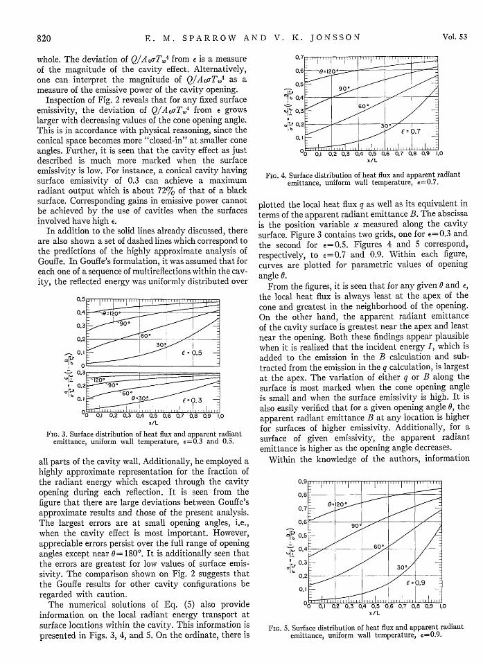
FIG. 4. Surface distribution of heat flux and apparent radiantemittance, uniform wall temperature, e=0.7.
plotted the local heat flux q as well as its equivalent interms of the apparent radiant emittance B. The abscissais the position variable x measured along the cavitysurface. Figure 3 contains two grids, one for E=0.3 andthe second for 6=0.5. Figures 4 and 5 correspond,respectively, to e= 0.7 and 0.9. Within each figure,curves are plotted for parametric values of openingangle 0.
From the figures, it is seen that for any given 0 and 6,
the local heat flux is always least at the apex of thecone and greatest in the neighborhood of the opening.On the other hand, the apparent radiant emittanceof the cavity surface is greatest near the apex and leastnear the opening. Both these findings appear plausiblewhen it is realized that the incident energy I, which isadded to the emission in the B calculation and sub-tracted from the emission in the q calculation, is largestat the apex. The variation of either q or B along thesurface is most marked when the cone opening angleis small and when the surface emissivity is high. It isalso easily verified that for a given opening angle 0, theapparent radiant emittance B at any location is higherfor surfaces of higher emissivity. Additionally, for asurface of given emissivity, the apparent radiantemittance is higher as the opening angle decreases.
Within the knowledge of the authors, information
039
0.8 -
0.I ~ ~ ~ ~ 6 .
0O 0.1 0.2 0.3 0.4 0.5 0.6 0.7 0.8 0.9 1.0x/L
FIG. 5. Surface distribution of heat flux and apparent radiantemittance, uniform wall temperature, 6=0.9.
030 . -
,- = 0~~e..5 +_
.5
.2
.1 :: 0-30, 3 --E
(I- __ - - '',
Vol1. 53
. PI b
.1 -,
I
. 7
I

DIFFUSE CONICAL CAVITIES
of the type given on Figs. 3, 4, and 5 does not elsewhereappear in the literature and therefore comparisonscannot be made.
Uniform Wall Heat Flux
Corresponding to a uniform heat flux q, the radiantflux Q streaming from the cavity may be calculateddirectly from the first member of Eq. (9) as
Q=q,7rL 2 sin(0/2).
M101
"U11
'11.I
b1cr
(20)
However, since there is no single temperature whichcharacterizes the cavity, one cannot logically define ahemispherical emissivity for the cavity as a whole aswas done previously for the case of uniform walltemperature.
The local radiant transport results have been ob-tained from solutions of Eq. (11) for opening angles of 300, 60°, 900, and 1200. This information is plottedin Fig. 6 in terms of the local apparent radiant emittanceand the local surface temperature. The curves areparametrized by the opening angle. Inspection of thefigure reveals that both the apparent radiant emittanceand the surface temperature achieve maximum valuesat the apex and decrease continuously as one proceedsaway from the apex. The surface variation of thesequantities is accentuated at small opening angles.Additionally, both the apparent radiant emittance andthe temperature increase as the opening angle de-
x/L
FIG. 6. Surface distribution of temperature and brightness,uniform wall heat flux.
creases. The apparent radiant emittance is independentof surface emissivity; but the surface temperature ishigher for surfaces of lower emissivity. Numericallyspeaking, the effect of emissivity on the temperatureis diminished at small opening angles.
ACKNOWLEDGMENT
This research was sponsored by the National Aero-nautics and Space Administration under the technicalsupervision of Mr. S. Lieblein, Chief, Flow ProcessesBranch of the NASA Lewis Research Center.
July 1963 821