Embed Size (px)
DESCRIPTION
Iabmas paper
Citation preview

1 INTRODUCTION
Cable-stayed bridges are modern solutions offering important advantages: the possibility to cover large spans and through this reducing the number of sub-structure elements, a relative small construction depth together with a good esthetic.
In the design stage of such type of bridge, several parameters concerning the bridge geometry are to be considered: span length, height of the pylons, the number and distribution of stays along the bridge deck. From these, the number and position of stays plays a very important role from possible further strengthening point of view. A large number of stays together with an optimized distribution can lead to major advantages, if stays damages occur or if the strengthening of bridge is necessary in order to ful-fill the new traffic requirements.
In this paper, the strengthening of an old cable-stayed bridge over Danube at Agigea is presented. The bridge was built in 1984 as a cable-stayed of asymmetrical type, having one pylon placed on the left bank of the Danube-Black Sea Canal. The erec-tion of the bridge superstructure was done by the aid of a temporary scaffolding system. During the de-sign stage, the different elongation capabilities of stay cables and protection steel tubes was not ac-counted for. Thus, after dismounting the scaffolding system in order to transfer the loads to the cable stays, under the self-weight of the superstructure, some of the steel tubes were broken at their ends and
through this, the corrosion of the strands was not en-sured anymore.
The lack in maintenance and the climatic condi-tions on the site have led to severe corrosion of the strands and a large number of them failed by rup-ture. Because the number a broken wires increases with time, the strengthening of the bridge should be performed quickly. The bridge closure is not possi-ble because it is the shortest link with the Constanţa harbor and with the Romanian coast of the Black Sea, which is visited each year by a large number of tourists.
The geometry of the bridge and the small number of stays made very difficult the strengthening pro-cess. Several solutions for the strengthening were discussed taking into account the advantages and disadvantages of each one, especially from econom-ic point of view, but considering also the technical aspects related to the efficiency of the applied meth-od and its impact on the bridge safety during the fu-ture service period.
The goal of the paper is to describe the chosen strengthening method together with the calculations performed for the design of temporary supplemen-tary structural elements used during the entire pro-cess.
2 DESCRIPTION OF THE BRIDGE
The bridge is placed on the national road DN39 Constanţa-Mangalia at km 8+988 in Agigea city,
Strengthening of the cable-stayed bridge over Danube at Agigea
I.R.Răcănel Technical University of Civil Engineering of Bucharest, Romania
C.S.Mutu Bridges Department, Design Institute for Road, Water and Air Transport, Romania
ABSTRACT: In the design of a bridge structure the optimization process plays an important role. This pro-cess includes economic aspects, strength and safety conditions and maintenance, retrofitting and strengthen-ing possibilities during service life. Sometime, a good solution from strength, safety and esthetics point of view can lead at major difficulties for maintenance and strengthening. In the design stage of a cable-stayed bridge, several parameters are to be considered. From these, the number and position of stays plays a very important role from strengthening point of view, a large number of stays making easier such a process. In this paper, the strengthening of an old cable-stayed bridge over Danube at Agigea is presented. The bridge was built in 1984 and the lack in maintenance and the climatic conditions on the site have led to severe corrosion of the wires in the stays and the strengthening of the bridge should be performed quickly.

near to the confluence between Danube-Black Sea Canal and Black Sea. The total bridge length is 307.70m and is covered by four spans:
40.50+40.50+162.00+23.00m. A general layout of the bridge is shown in Figure 1.
Figure 1. General layout of the bridge The bridge superstructure is a composite structure consisting in a steel deck connected at the upper part with a reinforced concrete slab. In cross section there are two groups of two steel plate girders which are forming the main girders of the superstructure. The distance between these two groups of girders is 14.00m and between the girders in a group is 2.00m. The girders webs are 3000mm deep. In order to re-duce the span of the concrete slab, three rows of welded I-shaped longitudinal stringers are foreseen. Transversally, the main girders and the stringers are connected using cross beams. The cross beams on the abutments, piers and pylon, together with those where the anchorages for the stays are disposed, have welded steel box cross sections. The current cross beams have I-welded cross sections and they are placed at 7.84m along the bridge. All cross beams have the total depth of 2050mm. The steel deck is connected with the reinforced concrete slab disposed above it using steel studs.
The substructure of the bridge consists in two massive abutments, two piers having a lamellar ele-vation and an A-shaped pylon. The pylon comprises two inclined concrete legs with variable dimensions. At the bottom part, the cross section of the pylon legs is a full concrete rectangular section having the 5.50m in bridge longitudinal direction and 3.25m in transverse direction. Starting at 12.50m above the foundation, the cross sections of the pylon legs be-came concrete boxes with variable dimensions: from 5.05m to 3.15m in longitudinal direction and 3.25m
transversally. The total height of the pylon above the upper part of the foundation mat is 78.70m. All sub-structure elements have deep foundations on con-crete piles of 1.08 (abutments and pier P1) and of 1.50m (pylon and pier P2) and variable length.
The bearing of the superstructure on the substruc-ture elements is made through steel bearing devices. The superstructure extremity towards Constanţa was anchored in the abutment by means of two L-shaped steel structures, welded at the upper part on the deck girders and resting at the bottom part on bearings placed upside-down in order to take the tensile forc-es caused by the presence of the loads on the unbal-anced spans of the bridge.
The superstructure is supported by stay cables which are anchored at the top of the pylon. For each stay cable 48Ø5mm SBP I wires were used. The strands were introduced in steel tubes in order to en-sure the protection against corrosion.
Figure 2 Cross section of the bridge superstructure

A cross section of the bridge superstructure is pre-sented in Figure 2.
3 STRENGTHENING SOLUTIONS
The large number of wires broken in a short time pe-riod lead to the conclusion that the bridge should be strengthened as soon as possible. Several solutions were proposed for strengthening and they will be briefly presented in the following. The choosing of the appropriate solution was based on the simplicity in execution, efficiency in use during strengthening time period and in the future in service and on nec-essary costs.
In the first solution (Fig. 3), a temporary bearing steel structure should be placed in the largest span, under the stays A4 and A7 (Fig. 1). The foundation of this structure should be placed on the bottom of the Canal Danube-Black Sea, on a special existing concrete block that was foreseen during the execu-tion of the Canal. This structure should allow the bearing of the superstructure ensuring it’s stability during strengthening process, by reducing the span value and through this the value of the vertical de-formations, which could be caused by the collapse of one or more stays. This solution had a major disad-vantage: it’s strongly reduces the clearance, increas-ing the risk of collision of the temporary tower and the ships and loaded barges traveling on the Canal.
Figure 3. First strengthening solution
The second solution (Fig. 4) consists in building of a new pylon on the right bank of the Canal to-gether with a concrete anchorage block for the back-stays. Both, the pylon and the anchorage block had deep foundations on large diameter concrete piles. Three pairs of stays should ensure the suspension of the bridge in the larger span being connected to the superstructure near to the existing cable-stays A3-A8, A4-A7, A5-A6. The disadvantages of this solu-tion are linked with the difficulty in execution of foundations and elevation of the new pylon and with the lack of space behind the abutment Mangalia. Moreover, the new anchorages needed for the tem-porary stays could lead to difficulties during the changing process of the damaged stays. For these reasons this solution was also rejected.
The third solution is presented in Figure 5. In this solution, the pylon and the existing stays are kept
and supplementary, several pairs of stays are added in order to support the deck. The anchorages of the existing stays A3-A8, A4-A7, A5-A6 are kept at the deck level, but those placed at the top of the pylon are disaffected. In order to allow the connection of the stays on the pylon, at its top, a special composite (steel-concrete) structure was foreseen. This solution has a major advantage: the larger number of stays will ensure a better behavior of the bridge under ser-vice loads and will allow an easier change process if further strengthening are necessary. Moreover, it is a significant improvement from esthetical point of view. The disadvantage of the solution is related with the high consumption of steel because of the larger number of stays and the steel special struc-tures necessary to fix the stays at the deck and pylon respectively. Also, especially at the deck level, the construction of the anchorages for the new stays will be complicated implying other supplementary sys-tems on the deck. It was concluded that the solution will have an important impact on the total costs fore-seen for the bridge strengthening and it was also re-jected.
Figure 4. Second strengthening solution
Figure 5. Third strengthening solution
The last proposed solution, which is also the adopted one, is presented in Figure 6. In this solution five pairs of supplementary temporary stays should be added in order to support the deck during the strengthening process. The solution implies the exe-cution of new steel structures placed below the deck and at the top of the pylon to anchor the stays at both ends. Adapting the cross section of the new tempo-rary stays to the stress level required by the breaking of the wires in old stays and optimizing the dimen-sions of the supplementary steel structures recom-mend this solution as the most effective from costs and time required to execute it. This solution was accepted and detailed in the project for the bridge strengthening. In the figure below, in plan view, the
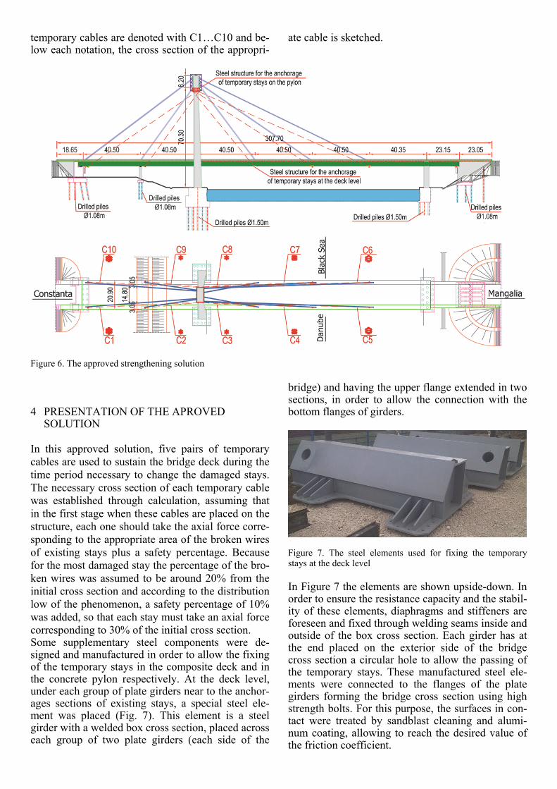
temporary cables are denoted with C1…C10 and be-low each notation, the cross section of the appropri-
ate cable is sketched.
Figure 6. The approved strengthening solution
4 PRESENTATION OF THE APROVED SOLUTION
In this approved solution, five pairs of temporary cables are used to sustain the bridge deck during the time period necessary to change the damaged stays. The necessary cross section of each temporary cable was established through calculation, assuming that in the first stage when these cables are placed on the structure, each one should take the axial force corre-sponding to the appropriate area of the broken wires of existing stays plus a safety percentage. Because for the most damaged stay the percentage of the bro-ken wires was assumed to be around 20% from the initial cross section and according to the distribution low of the phenomenon, a safety percentage of 10% was added, so that each stay must take an axial force corresponding to 30% of the initial cross section. Some supplementary steel components were de-signed and manufactured in order to allow the fixing of the temporary stays in the composite deck and in the concrete pylon respectively. At the deck level, under each group of plate girders near to the anchor-ages sections of existing stays, a special steel ele-ment was placed (Fig. 7). This element is a steel girder with a welded box cross section, placed across each group of two plate girders (each side of the
bridge) and having the upper flange extended in two sections, in order to allow the connection with the bottom flanges of girders.
Figure 7. The steel elements used for fixing the temporary stays at the deck level In Figure 7 the elements are shown upside-down. In order to ensure the resistance capacity and the stabil-ity of these elements, diaphragms and stiffeners are foreseen and fixed through welding seams inside and outside of the box cross section. Each girder has at the end placed on the exterior side of the bridge cross section a circular hole to allow the passing of the temporary stays. These manufactured steel ele-ments were connected to the flanges of the plate girders forming the bridge cross section using high strength bolts. For this purpose, the surfaces in con-tact were treated by sandblast cleaning and alumi-num coating, allowing to reach the desired value of the friction coefficient.

The connection of the temporary cables on the concrete pylon was made through a steel structure which form a steel ring around the top of the pylon (Fig. 8). In order to respect the clearance gauge on the roads from the factory to the site, this structure is composed from two subassemblies which were con-nected using high strength bolts with a diameter of 36mm. In bridge longitudinal direction, the ring cross section is a welded steel box with three webs having a depth of 2350mm. The exterior webs have the same inclination with respect to the horizontal as the lateral inclined legs of the pylon. In bridge trans-verse direction, on the side of Mangalia city, the ring cross section is a box with two webs having the same depth as for the parts disposed in bridge longi-tudinal direction. On the side of Constanţa city, two webs were also used for the ring cross section, but their depth is only 1450mm. Inside of all girders di-aphragms were placed in order to avoid the local buckling of the webs and flanges in compression. In the steel plates forming the bottom flanges of the box steel girders placed along the bridge as well as in the interior diaphragms, visiting holes were fore-seen in order to allow the welding (Fig. 9). Also, steel tubes of appropriate diameters were welded in-side the box sections allowing the passing through of temporary cables (Fig. 9).
Figure 8. One subassembly of the ring For both subassemblies on one side, two truss canti-levers with special baskets were foreseen. Adding calculated counterweights in the basket, the equilib-rium of the subassembly could be kept during the as-sembling on the site made with the aid of two cranes (Fig. 10).
Using the cranes, after bolting the joints between the two subassemblies, the ring was lowered down on the pylon until it stops. In order to avoid the damage of the concrete in the pylon because of high pressures produced by the ring, special mortars were injected between the parts in contact.
According to the climate on the site and for man-ufacturing purposes all steel elements were made in steel S355J2W+N.
Figure 9. Bottom view of the steel ring with visiting holes
Figure 10. One of two subassemblies equipped with truss canti-levers prepared for lifting After placing on the bridge superstructure and on the pylon these additional steel elements, the first stage of tensioning of the temporary cables was per-formed. During this operation, only for short time periods, the traffic on the bridge was restricted. Af-ter the first stage of tensioning, the level of axial forces in the temporary cables, as well of the vertical and horizontal displacements of the deck and pylon respectively were measured and compared with the calculated values. The values were in very good ac-cordance and will be briefly presented in a table in the next paragraph of the paper. In order to achieve the desired deformed shape of the deck needed for changing the damaged stays, a second stage of ten-sioning was performed. The level of the axial forces in the temporary cables for this stage were also cal-culated and delivered on the site to the builder. The new values of the vertical superstructures displace-ments corresponding to the new axial forces in the temporary stays measured on the site were in good accordance with the calculated values.
For the changing of the damaged stays, three sce-narios were considered and they will be described in the following.
In the first solution (Fig. 11) the existing stays are changed one by one, symmetrically with respect to the longitudinal axis of the bridge. The new stays
Zone for the anchorage oftemporary cables
Final plates for the bolted con-nections of two subassemblies

will have circular cross sections. The area of each cross section was established through numerical cal-culation, so that after all tensioning stages and re-moving of the temporary cables, the deformed shape of the bridge is identical with those at the time when the bridge was putted in service. To limit the dis-placement of the pylon during the change of final stays on Constanţa side, temporary back-stays were added on the structure (Fig. 11).
Figure 11. First solution for the change of existing stays In the second solution (Fig. 12), the existing stays are changed also one by one, symmetrically on two sides of the bridge, but the existing strands are taken out progressively and replaced with new stays of circular form. This time, the existing stays C1-C10 and C5-C6 were replaced each by three equivalent stays and stays C4-C7 by two equivalent stays. The diameters of these new stays are smaller with respect to those used in the first solution.
Figure 12. The second solution for the change of existing stays The third solution consists in changing the strands forming the cross section of each existing stay, one by one and replacing them by new undamaged strands (Fig. 13). This operation will be done also symmetrically with respect to the bridge longitudinal axis.
The first and the second solution have the ad-vantage that the new stays will have a compact cir-cular shape of the cross section, reducing the unfa-vorable effect of wind and improving the bridge behavior. Also, the time required for the changing process is significantly smaller comparing with the
third solution. The disadvantage in both solutions is related with the higher values of the axial forces in temporary cables and remaining stays during the changing process. One major advantage of the third solution is that the both, at the deck level and at the top of the pylon, the existing anchorage zones can be kept unchanged or will suffer only minor changes. Analyzing these aspects the third solution was pre-ferred, even the time necessary for changing all damaged cables increases significantly.
Figure 13. The third solution for the change of existing stays
5 FINITE ELEMENT MODELS, PERFORMED ANALYSES AND RESULTS
In order to establish the stress state in the structural elements and the displacements level of the bridge components before, during and after strengthening process, several finite elements were built. Using these finite elements, linear and nonlinear static analyses were performed and based on these, the de-sign of the new introduced steel components, tempo-rary cables and new stays could be performed.
For establishing the stress state in the existing, temporary and new cables of the bridge a full 3D fi-nite element model was used (Fig. 14).
Figure 14. The used global finite element model For the piers and pylon two joint straight frame fi-nite elements were used. The stay-cables were mod-eled using cable finite elements with nonlinear be-havior, which can take into account the changing in stiffness due to the axial force level and the de-

formed shape of the cable. For the deck, four nodes finite elements with combined membrane and shell behavior were used (Fig. 15).
Figure 15. Detailed view of the finite element model at the deck level The values of the axial forces in the damaged cables at the moment of introduction in the structure of temporary cables was established based on a nonlin-ear staged analysis, considering all the execution stages performed until the opening of the bridge in 1984. Based on the observations on the site per-formed and summarized each week, the area of the remaining cross section of each cable was estimated and starting from this parameter, the necessary cross section of each temporary cable and the correspond-ing value of the axial forces needed for tensioning could be calculated. Table 1. Measured on the site and calculated values of the axial forces in temporary cables in the first tensioning stage __________________________________________________ Cable Measured axial force Calculated axial force ________________ ___________________ kN kN __________________________________________________ C1 2216.90 2173.10 C10 2215.50 2174.00 C2 592.70 734.40 C9 500.20 734.50 C3 1016.00 948.60 C8 966.70 956.30 C4 879.30 816.70 C7 846.60 818.90 C5 1175.70 1027.80 C6 1151.30 1029.60 In Table 1 the calculated and measured on the site values of the tensioning forces for the first stage of strengthening are given. It can be seen that is a good accordance between measured and calculated values with one exception for the cables C2 and C9. These temporary cables are near to the pier P1 so they are not so efficient in reality. In the finite element model the real bearing of the structure on the pier could not be exactly modeled.
In order to change the existing damaged stay-cables, a desired calculated deformed shape of bridge was obtained by re-tensioning the temporary cables. Using these forces, the design of the steel structures, needed for the anchorage of temporary
cables, placed on the pylon and under the bridge deck could be performed. Thus, other finite element model were built and analyzed.
In Figure 16 a detailed deformed view of the fi-nite element model of the steel ring are presented. For the model, isoparametric thin shell finite ele-ments were used. Special supports conditions were imposed into the model in order to simulate the con-tact existing between the two lateral faces of the steel ring and the pylon legs. The loads acting on the model were considered the axial forces in the tempo-rary cables calculated using the global finite ele-ments model and the staged nonlinear analysis. For safety reasons, the axial forces were increased up to the values corresponding the ultimate resistance of the steel in the strands used for the temporary cables. Based on this, the considered dimensions for the cross section of the girders forming the ring as well the position and the thickness of steel plates could be checked. Under these extreme loading conditions, the displacements of some parts of the ring with the values of 2-3mm were below the allowable limits and equivalent von Mises stress distribution indi-cates that only punctually, the values are over-passing the yield strength of the steel with the max-imum values of 703N/mm2.
Figure 16. Detailed view of the deformed shape of the ring un-der considered loads In Figure 17 the contours of equivalent von Mises stresses are shown.
Figure 17. Contours of the von Mises stresses

A separate finite elements model (Fig. 18) was con-sidered for the steel elements placed under the bridge deck, where the anchorages for the temporary cables were placed. The gauge of these elements was limited, because there should be placed near to the anchorages of existing damaged cables.
Figure 18. Model used for the steel elements placed under the bridge deck
Figure 19. Contours of von Mises stresses under considered loads Using this model, these steel elements were checked in order to avoid resistance and loss of stability problems that can occur under the considered loads. Moreover, the bolted connections between the flang-es of the girders forming the bridge deck and the up-per flanges of the steel pieces used for the anchorag-es were also correct designed. The values of the displacements and the peak values of the von Mises stresses (Fig. 19) were below the allowable limits.
6 CONCLUSIONS
In this paper the strengthening solution of an old ca-ble-stayed bridge over Danube is presented. Due to the lack in maintenance and climatic conditions, the wires which are forming the existing stays suffered
severe damage by corrosion. Several solutions for the strengthening were studied and finally, based on technical, economical and ease in execution aspects, one solution was chosen. This solution implies to use of some temporary cables, appropriate ten-sioned, to sustaining the deck during the strengthen-ing process. The complexity of the problem lead to use of several complex finite elements models for establishing the deformations and stress state in all bridge elements and for the correct design of the new steel structural elements needed for the strengthening process.
At this time, the strengthening operation is going on and the bridge will regain a safety coefficient which allow the future use in very good conditions.
REFERENCES
Dumitrescu, N., Popa, N. and Popa, V., 1995. The new road bridges over the Romanian navigable canals. Proceedings of “The Second International Conference – Bridges over the Danube”, 11-15 September 1995, Bucharest, 347-356.
Gimsing, N.J., 1983. Cable Supported Bridges-Concept and Design. John Wiley&Sons Ltd., London.
Pododlny, W. and Scalzi, J.B., 1986. Construction and Design of Cable Stayed Bridges–Second Edition. John Wiley&Sons Ltd., London.
Troitsky, M.S., 1988. Cable Stayed Bridges: Theory and De-sign-Second Edition. BSP Professional Books.
Walther, R., Houriet, B., Isler, W., Moïa, P. and Klein, J.F., 1999. Cable Stayed Bridges-Second Edition. Thomas Tel-ford Publishing, London.
Mehlhorn, G., 2010. Handbuch Brücken. Entwerfen, Kon-struiren, Berechnen, Bauen und Erhalten. Springer Verlag Berlin.


