Embed Size (px)
Citation preview
Kyler Kitani
54602164
12/19/14
ANTEATER RACING PORTFOLIO (SAVAGE)
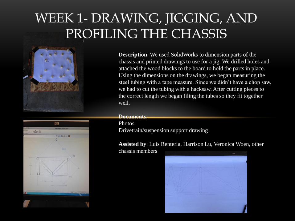
WEEK 1- DRAWING, JIGGING, AND PROFILING THE CHASSIS
Description: We used SolidWorks to dimension parts of the
chassis and printed drawings to use for a jig. We drilled holes and
attached the wood blocks to the board to hold the parts in place.
Using the dimensions on the drawings, we began measuring the
steel tubing with a tape measure. Since we didn’t have a chop saw,
we had to cut the tubing with a hacksaw. After cutting pieces to
the correct length we began filing the tubes so they fit together
well.
Documents:
Photos
Drivetrain/suspension support drawing
Assisted by: Luis Renteria, Harrison Lu, Veronica Woen, other
chassis members
WEEK 2- CUTTING AND PROFILING THE CHASSIS
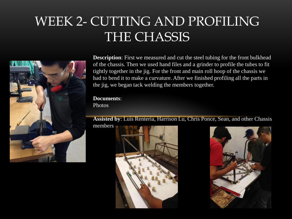
Description: First we measured and cut the steel tubing for the front bulkhead
of the chassis. Then we used hand files and a grinder to profile the tubes to fit
tightly together in the jig. For the front and main roll hoop of the chassis we
had to bend it to make a curvature. After we finished profiling all the parts in
the jig, we began tack welding the members together.
Documents:
Photos
Assisted by: Luis Renteria, Harrison Lu, Chris Ponce, Sean, and other Chassis
members
WEEK 3 - CUTTING, PROFILING, AND WELDING THE CHASSIS
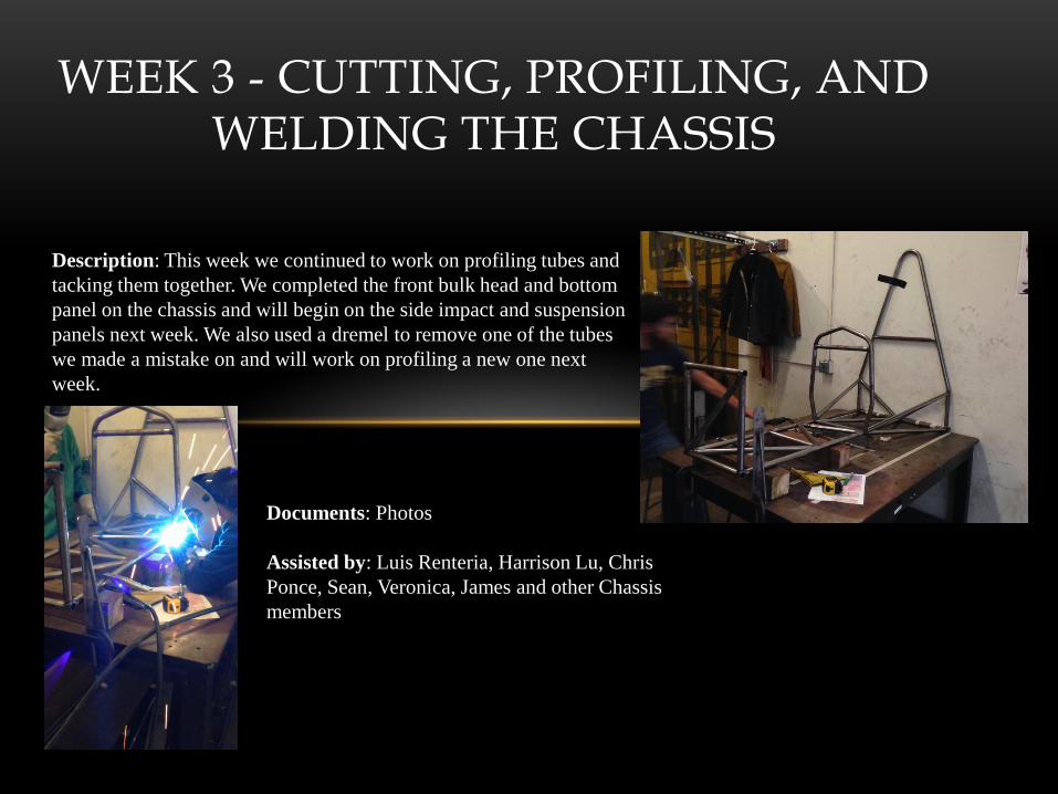
Description: This week we continued to work on profiling tubes and
tacking them together. We completed the front bulk head and bottom
panel on the chassis and will begin on the side impact and suspension
panels next week. We also used a dremel to remove one of the tubes
we made a mistake on and will work on profiling a new one next
week.
Documents: Photos
Assisted by: Luis Renteria, Harrison Lu, Chris
Ponce, Sean, Veronica, James and other Chassis
members

WEEK 4 – PROFILING AND WELDING THE CHASSIS
Description: This week we continued working on the chassis
and made good progress. We found a notcher which sped up the
profiling process tremendously. We completed the side panels
and next week we will be working on the cock pit and the
engine bay. Currently we are one week ahead of schedule.
Documents: Photos
Assisted by: Luis Renteria, Harrison Lu, Chris Ponce, Michael
Rodriguez, Veronica, James, Michael, and other members

WEEK 5 – SOLIDWORKS TESTING AND JIGGING
Description: This week we performed FEA tests on the chassis by
looking up the requirements in the FSAE rule book. Pictured below
is the results from the stress and displacement test. We also began
jigging for the engine bay of the chassis. Next week we will try to
finish profiling and welding the back side of the chassis.
Documents: Photos and Solidworks FEA
Assisted by: Luis Renteria, Harrison Lu, Chris Ponce, Michael
Rodriguez, Veronica, James, Michael, and other members
WEEK 6 – PROFILING AND WELDING THE CHASSIS
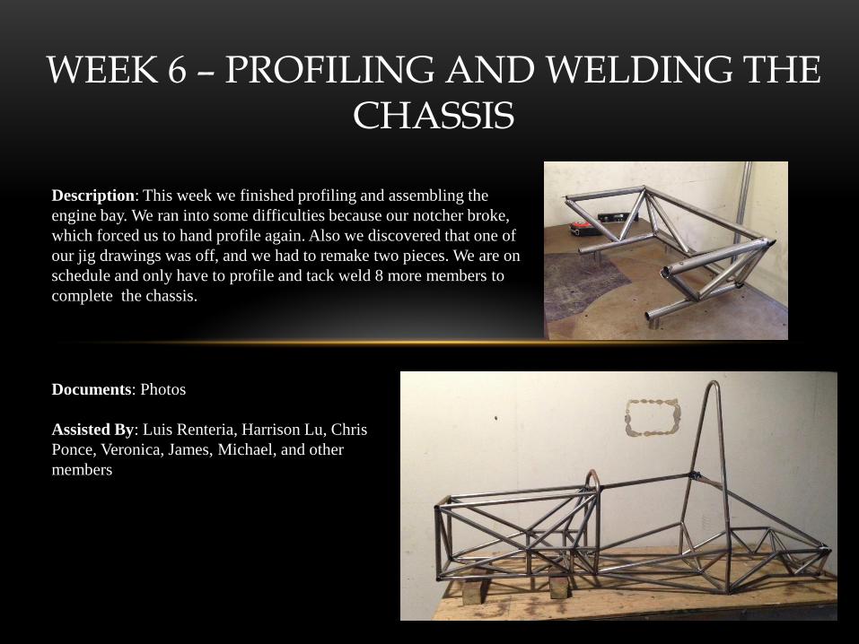
Description: This week we finished profiling and assembling the
engine bay. We ran into some difficulties because our notcher broke,
which forced us to hand profile again. Also we discovered that one of
our jig drawings was off, and we had to remake two pieces. We are on
schedule and only have to profile and tack weld 8 more members to
complete the chassis.
Documents: Photos
Assisted By: Luis Renteria, Harrison Lu, Chris
Ponce, Veronica, James, Michael, and other
members
WEEK 7 – PROFILING AND WELDING THE CHASSIS
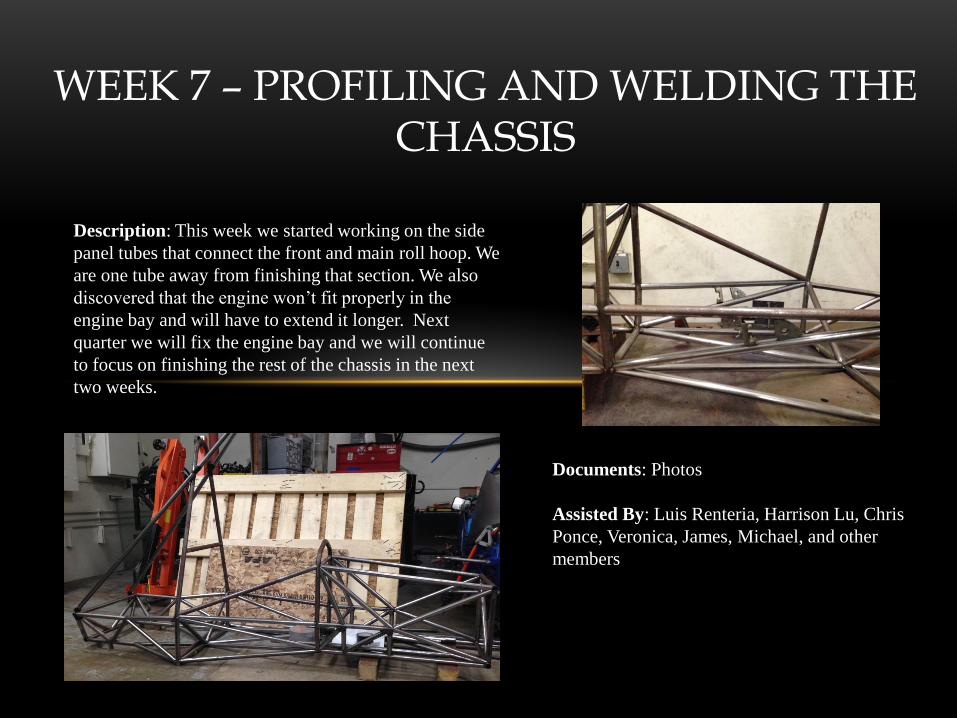
Description: This week we started working on the side
panel tubes that connect the front and main roll hoop. We
are one tube away from finishing that section. We also
discovered that the engine won’t fit properly in the
engine bay and will have to extend it longer. Next
quarter we will fix the engine bay and we will continue
to focus on finishing the rest of the chassis in the next
two weeks.
Documents: Photos
Assisted By: Luis Renteria, Harrison Lu, Chris
Ponce, Veronica, James, Michael, and other
members
WEEK 8 - PROFILING AND WELDING THE CHASSIS
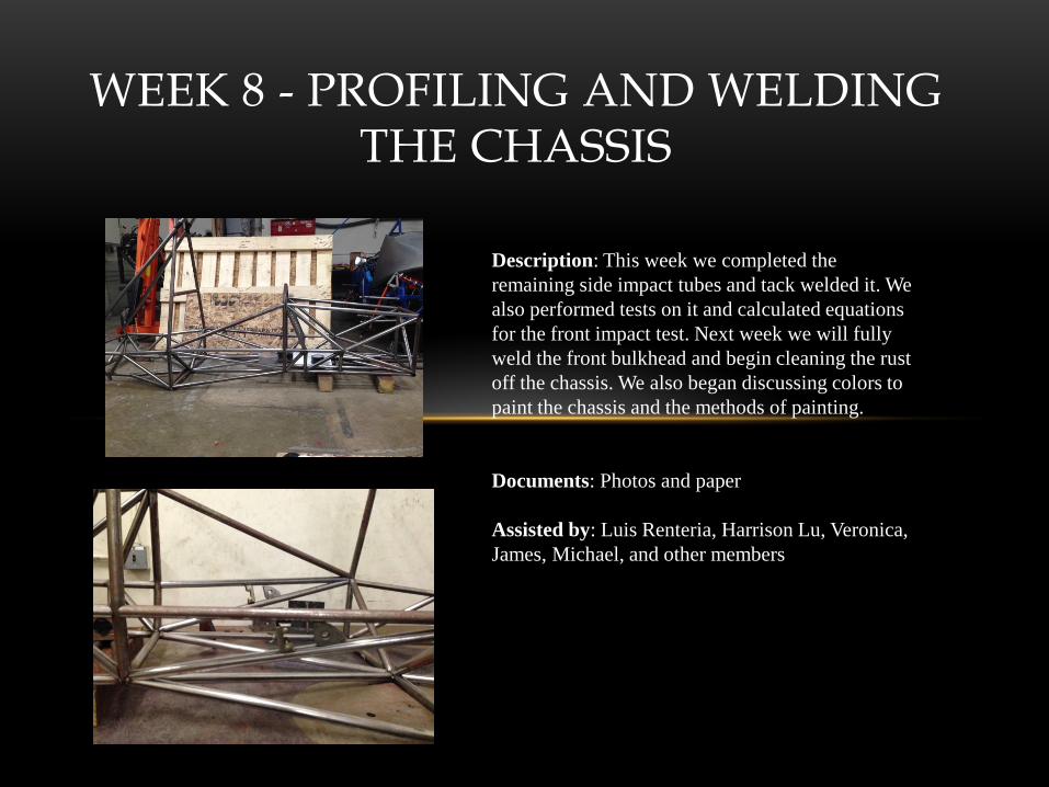
Description: This week we completed the
remaining side impact tubes and tack welded it. We
also performed tests on it and calculated equations
for the front impact test. Next week we will fully
weld the front bulkhead and begin cleaning the rust
off the chassis. We also began discussing colors to
paint the chassis and the methods of painting.
Documents: Photos and paper
Assisted by: Luis Renteria, Harrison Lu, Veronica,
James, Michael, and other members
WEEK 9 - CLEANING AND WELDING THE CHASSIS
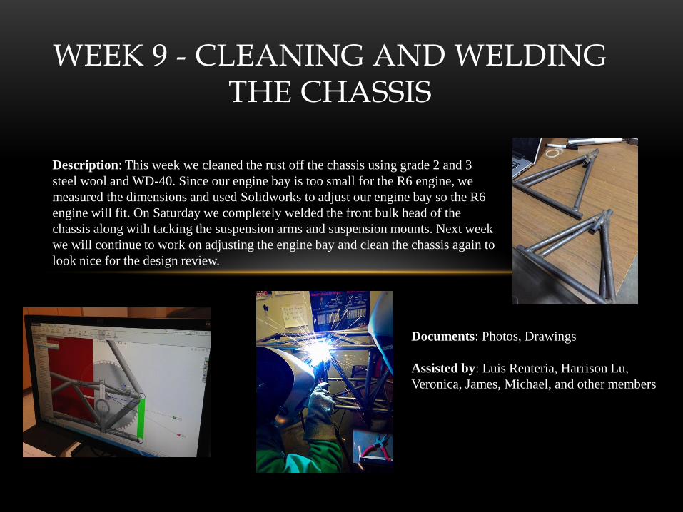
Description: This week we cleaned the rust off the chassis using grade 2 and 3
steel wool and WD-40. Since our engine bay is too small for the R6 engine, we
measured the dimensions and used Solidworks to adjust our engine bay so the R6
engine will fit. On Saturday we completely welded the front bulk head of the
chassis along with tacking the suspension arms and suspension mounts. Next week
we will continue to work on adjusting the engine bay and clean the chassis again to
look nice for the design review.
Documents: Photos, Drawings
Assisted by: Luis Renteria, Harrison Lu,
Veronica, James, Michael, and other members
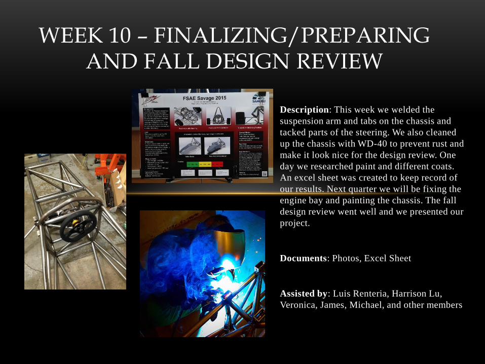
Description: This week we welded the
suspension arm and tabs on the chassis and
tacked parts of the steering. We also cleaned
up the chassis with WD-40 to prevent rust and
make it look nice for the design review. One
day we researched paint and different coats.
An excel sheet was created to keep record of
our results. Next quarter we will be fixing the
engine bay and painting the chassis. The fall
design review went well and we presented our
project.
Documents: Photos, Excel Sheet
Assisted by: Luis Renteria, Harrison Lu,
Veronica, James, Michael, and other members
WEEK 10 – FINALIZING/PREPARING AND FALL DESIGN REVIEW
Week 11 – Redesigning Chassis Engine Bay
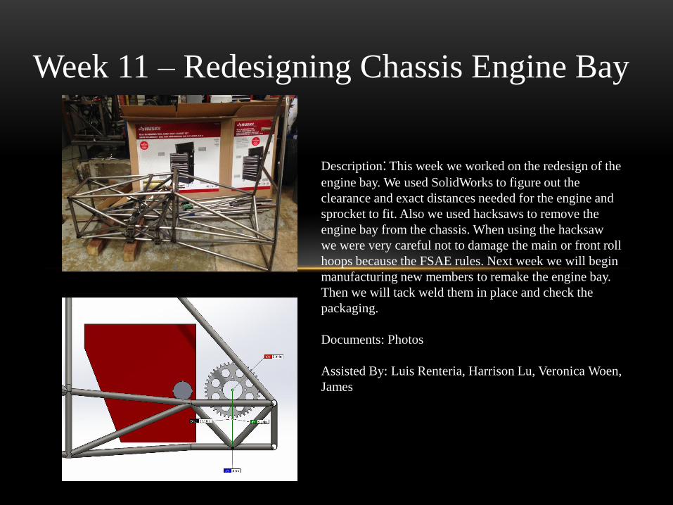
Description: This week we worked on the redesign of the
engine bay. We used SolidWorks to figure out the
clearance and exact distances needed for the engine and
sprocket to fit. Also we used hacksaws to remove the
engine bay from the chassis. When using the hacksaw
we were very careful not to damage the main or front roll
hoops because the FSAE rules. Next week we will begin
manufacturing new members to remake the engine bay.
Then we will tack weld them in place and check the
packaging.
Documents: Photos
Assisted By: Luis Renteria, Harrison Lu, Veronica Woen,
James

Week 12 – Redesigning of the Engine
Bay and Track Day
Description: This week we continued to redesign the engine
bay. We did a dry fit of the engine and sprocket and
measured the amount we needed to extend it. Then we
looked at the SolidWorks model to solidify our
measurements. On Saturday we also had track day and I was
able to drive Beta. Unfortunately I wasn’t able to drive Delta
because it broke down during track day.
Documents: Photos
Assisted By: Luis Renteria, Harrison Lu, Veronica Woen,
James

Week 13 – Manufacturing of Extended
Engine Bay
Description: This week we worked on manufacturing the
extended members of the engine bay. First we measured the
length of the tubing needed. Then we cut and profiled four
of the ten members. We were very cautious when making
the new members because we do not have much extra
material. After profiling them we tack welded them in
place. This week we will finish the remaining members and
work to finish the chassis.
Documents: Photos
Assisted By: Luis Renteria, Harrison Lu, Veronica Woen,
James
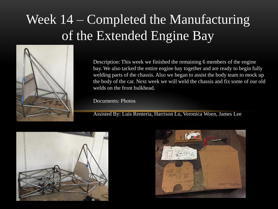
Week 14 – Completed the Manufacturing
of the Extended Engine Bay
Description: This week we finished the remaining 6 members of the engine
bay. We also tacked the entire engine bay together and are ready to begin fully
welding parts of the chassis. Also we began to assist the body team to mock up
the body of the car. Next week we will weld the chassis and fix some of our old
welds on the front bulkhead.
Documents: Photos
Assisted By: Luis Renteria, Harrison Lu, Veronica Woen, James Lee

Week 15 – Welding the Chassis and
Start Required Documentation
Description: This week we practiced our welding and began welding
the remaining parts of the chassis. We began taking a look at the
required documents we need to fill out for the chassis. We also
worked with the body team to assist with the mock up. Next week
we will finish welding the chassis and fill out the documents. We
will also begin looking into the impact attenuator.
Documents: Photos
Assisted By: Luis Renteria, Harrison Lu, Veronica Woen, James Lee
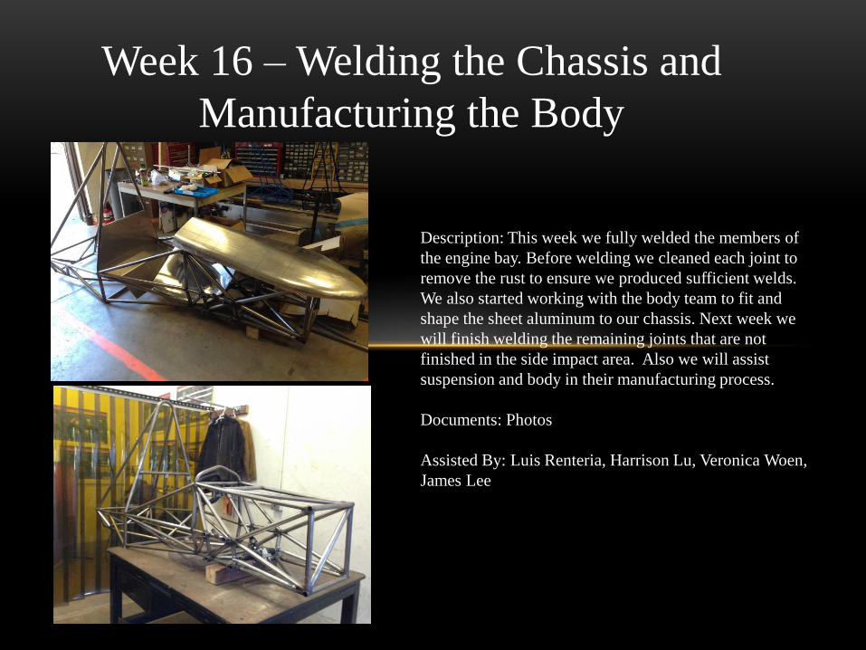
Week 16 – Welding the Chassis and
Manufacturing the Body
Description: This week we fully welded the members of
the engine bay. Before welding we cleaned each joint to
remove the rust to ensure we produced sufficient welds.
We also started working with the body team to fit and
shape the sheet aluminum to our chassis. Next week we
will finish welding the remaining joints that are not
finished in the side impact area. Also we will assist
suspension and body in their manufacturing process.
Documents: Photos
Assisted By: Luis Renteria, Harrison Lu, Veronica Woen,
James Lee
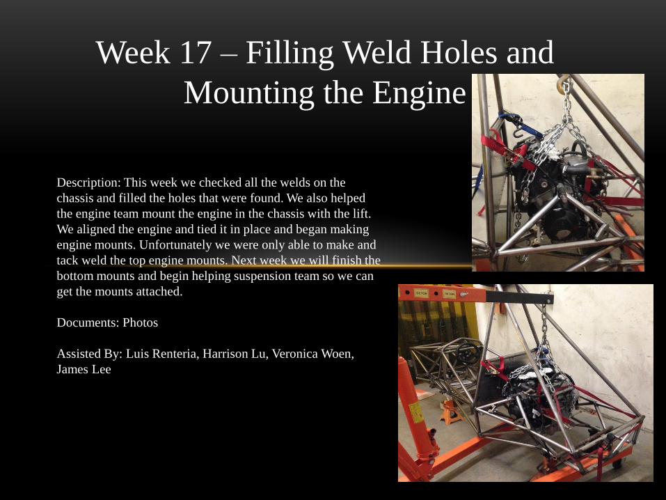
Week 17 – Filling Weld Holes and
Mounting the Engine
Description: This week we checked all the welds on the
chassis and filled the holes that were found. We also helped
the engine team mount the engine in the chassis with the lift.
We aligned the engine and tied it in place and began making
engine mounts. Unfortunately we were only able to make and
tack weld the top engine mounts. Next week we will finish the
bottom mounts and begin helping suspension team so we can
get the mounts attached.
Documents: Photos
Assisted By: Luis Renteria, Harrison Lu, Veronica Woen,
James Lee
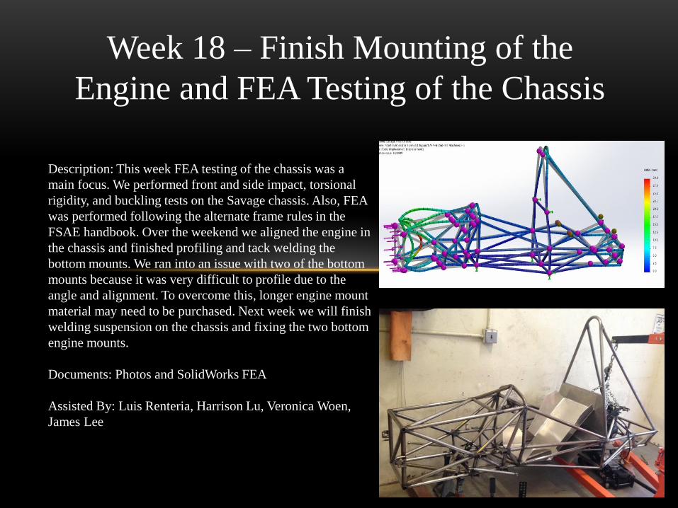
Week 18 – Finish Mounting of the
Engine and FEA Testing of the Chassis
Description: This week FEA testing of the chassis was a
main focus. We performed front and side impact, torsional
rigidity, and buckling tests on the Savage chassis. Also, FEA
was performed following the alternate frame rules in the
FSAE handbook. Over the weekend we aligned the engine in
the chassis and finished profiling and tack welding the
bottom mounts. We ran into an issue with two of the bottom
mounts because it was very difficult to profile due to the
angle and alignment. To overcome this, longer engine mount
material may need to be purchased. Next week we will finish
welding suspension on the chassis and fixing the two bottom
engine mounts.
Documents: Photos and SolidWorks FEA
Assisted By: Luis Renteria, Harrison Lu, Veronica Woen,
James Lee
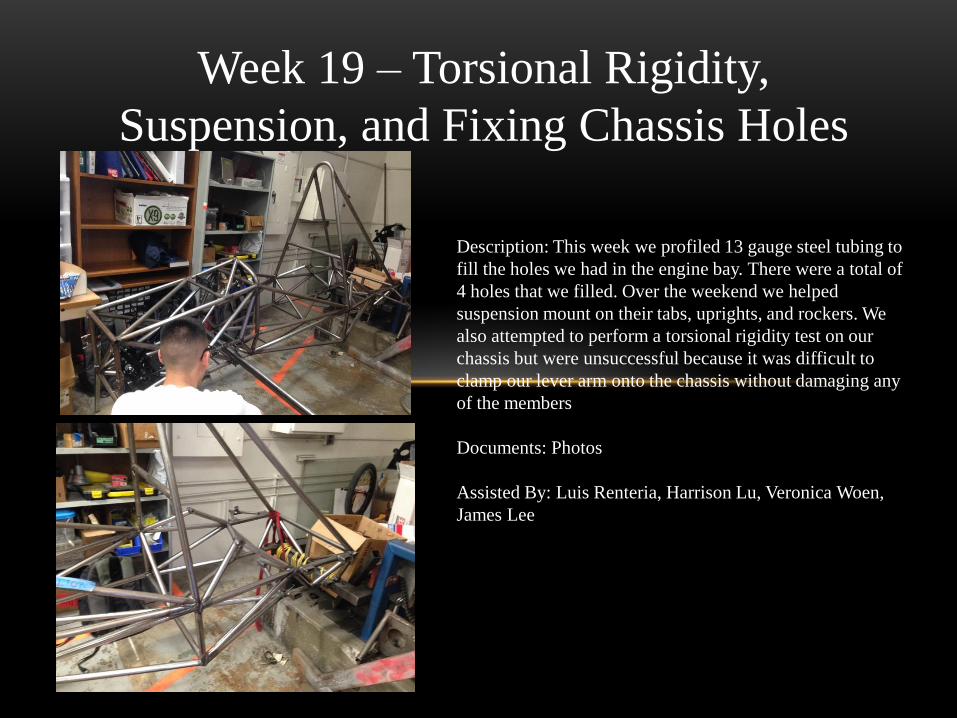
Week 19 – Torsional Rigidity,
Suspension, and Fixing Chassis Holes
Description: This week we profiled 13 gauge steel tubing to
fill the holes we had in the engine bay. There were a total of
4 holes that we filled. Over the weekend we helped
suspension mount on their tabs, uprights, and rockers. We
also attempted to perform a torsional rigidity test on our
chassis but were unsuccessful because it was difficult to
clamp our lever arm onto the chassis without damaging any
of the members
Documents: Photos
Assisted By: Luis Renteria, Harrison Lu, Veronica Woen,
James Lee
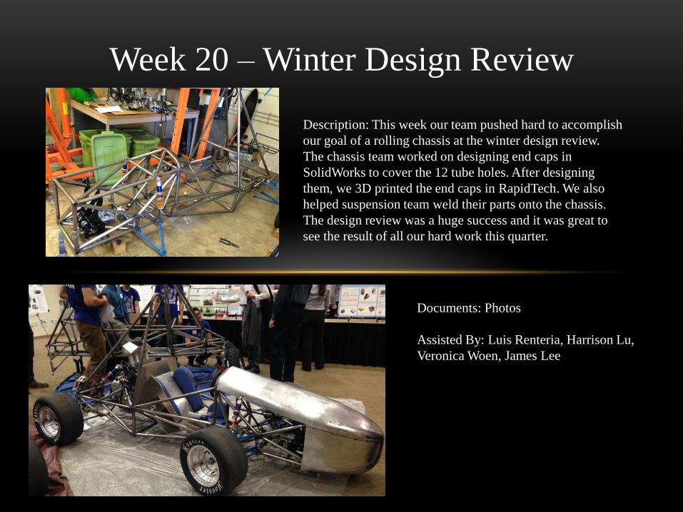
Week 20 – Winter Design Review
Description: This week our team pushed hard to accomplish
our goal of a rolling chassis at the winter design review.
The chassis team worked on designing end caps in
SolidWorks to cover the 12 tube holes. After designing
them, we 3D printed the end caps in RapidTech. We also
helped suspension team weld their parts onto the chassis.
The design review was a huge success and it was great to
see the result of all our hard work this quarter.
Documents: Photos
Assisted By: Luis Renteria, Harrison Lu,
Veronica Woen, James Lee