Embed Size (px)
Citation preview

1
0243EN October 2015Solar thermal SyStemS
One-way circulatiOn grOupfOr sOlar thermal systemsr586s-0
ISO140010032A/3
OHSAS180010064L/1
ISO90010006/7
DescriptionThe R586S-0 preassembled one-way circulation group has been designed to guarantee utmost operational reliability, dimension compactness and, last but not least, simplified installation and service of solar thermal systems.The circulation group includes:• ErP-complying circulator, specific for solar applications, controlling the thermo-conductor fluid flow based on the settings of the regulation unit. The ball valves installed on the bottom and top enable to maintain the system without emptying the circuit.• Mechanical flow meter to directly calculate the thermal energy provided by the solar panels.• Room for installation of electronic regulation unit and Pt1000 temperature sensors.• Filling group including filling and drain taps and regulation valve.• Safety group with 6 bar calibrated safety valve, complying with the PED (97/23/CE - Cat. IV) rule, pressure gauge and outlet for connection to expansion tank.• Ball valve with integrated check valve and thermometer to read solar circuit delivery temperatures.• PPE insulation cover to ensure an efficient thermal insulation. It includes two removable spacers to install the regulation unit on the group side and carry out adjustment, filling and draining of the system; the cover also enables to view the thermometer mounted on the return valve, the pressure gauge mounted on the safety group, air circulation for cooling of the integrated circulator and, by means of a steel plate on the back, installation on boilers or walls.
Versions and product codesCirculation group Differential control unit
Type of flow meterSeries Product code Series Product code
R586S-0 R586SY002 KTD3 or KTD5(sold separately)
KTD3Y003KTD5Y006 mechanical
Spare parts• KTDPY001: overvoltage protection for KTD control units• KTDSY001: Pt1000 temperature sensor (180 °C)• P586S: spare parts for solar circulation groups• P586S-3: connection kit for solar circulation groups
Optionals• KTD differential control unit: for programming and operational control of solar thermal systems. Available in two versions, KTD3 and KTD5, sold separately. A user-friendly control unit with backlit graphic display, four buttons, convenient programming assistant and help texts that can be recalled in line. It is equipped with Pt1000 temperature sensors, outlet relay for control of the electronic circuit and one or two outlet relays to control a pump (activation/deactivation) or a motorized valve (opening/closing). The control unit programs enable to set various system configurations. The operational control functions range from reading the current measured values up to analysis and long-term monitoring through diagrams and statistics. The KTD3 and KTD5 versions enable to easily register the thermal energy produced by the solar system by setting additional parameters (glycol type and percentage, system capacity).
• VES expansion tank: a safety device for solar thermal systems; it compensates the thermal expansion of thermo-convector fluids caused by high temperature fluctuations inside the solar circuit. Installation of an expansion tank prevents each pressure increase inside the solar circuit from activating the safety valve, even when not required. Available versions range from 8 to 300 l; the special VES-2 (code: VESY020) fitting bracket, equipped with a double check valve, can be used with the 8 - 35 l versions.
R586S-0
2
0243EN October 2015Solar thermal SyStemS
One-way circulatiOn grOupfOr sOlar thermal systemsr586s-0
ISO140010032A/3
OHSAS180010064L/1
ISO90010006/7
Technical data• Thermo-conductor fluid: water or glycol-based solutions (max. 50 % of glycol)• Max. working temperature: 110 °C at Troom ≤ 55 °C• Nominal pressure: PN10• Safety valve calibration pressure: 6 bar• Circulator: 25/6 - center distance 130 mm - ErP compatible Two operational options: 3 speeds or variable lift• Circulator power: 230 Vac - 50 Hz (molex connector included)• Mechanical flow meter: 2÷12 l/min• Pressure gauge scale: 0÷10 bar• Thermometer scale: 0÷120 °C• Solar circuit outlets: 3/4”M (center distance: 125 mm)• Boiler circuit outlets: 3/4”M (center distance: 125 mm)• Safety valve discharge: 3/4”F• Expansion tank outlet: 3/4”M• Filling/drain taps with hose connection: Ø15 mm• Insulation cover: PPE, density 70 kg/m³
Circulator characteristicsThere are three operational modes available for the 25/6 circulator: three speeds, minimum speed or variable lift.
• Moving the knob to the left sets the maximum lift defining the range between which the circulator sets the speed.• Moving the knob to the right sets the operational speed (constant) of the circulator. • Moving the knob to the center (Min) sets the circulator minimum speed.
6
5
4
3
2
1
00 0,5 1 1,5 2 2,5 3 Q [m3/h]
Q [m3/h]
H [m]
00 0,5 1 1,5 2 2,5 3
20
40
P1 [w]
6
5
4
3
2
1
00 0,5 1 1,5 2 2,5 3 Q [m3/h]
Q [m3/h]
H [m]
00 0,5 1 1,5 2 2,5 3
20
40
P1 [w]max max
800 l/min
2390 l/min
3400 l/min
4300 l/min
Variable lift 3 speed
6
5
4
3
2
1
00 0,5 1 1,5 2 2,5 3 Q [m3/h]
Q [m3/h]
H [m]
00 0,5 1 1,5 2 2,5 3
20
40
P1 [w]
6
5
4
3
2
1
00 0,5 1 1,5 2 2,5 3 Q [m3/h]
Q [m3/h]
H [m]
00 0,5 1 1,5 2 2,5 3
20
40
P1 [w]max max
800 l/min
2390 l/min
3400 l/min
4300 l/min
Variable lift 3 speed
Circulator functioningThe 25/6 circulator can adjust the lift between the H and H/2 setting points by reducing the speed when the system losses of pressure increase.
Settingpoint “H”
Q [m3/h]
H [m]
Qmax
=
=
“H/2”
Varia
ble
lift
Valves closing
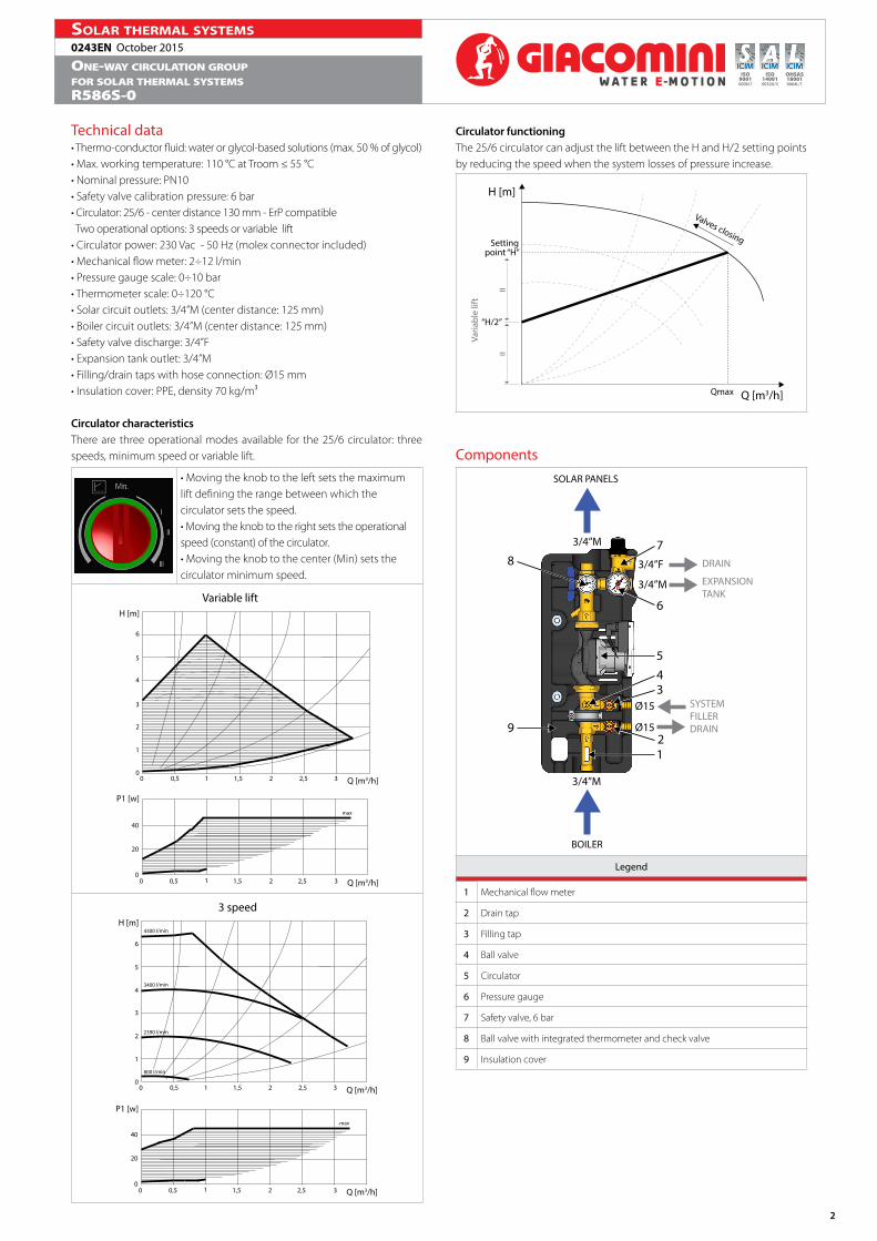
ComponentsSOLAR PANELS
BOILER
1
5
2
6
3
7
4
8
9
EXPANSIONTANK
SYSTEM FILLERDRAIN
DRAIN
3/4”M
3/4”F
3/4”M
Ø15
Ø15
3/4”M
Legend
1 Mechanical flow meter
2 Drain tap
3 Filling tap
4 Ball valve
5 Circulator
6 Pressure gauge
7 Safety valve, 6 bar
8 Ball valve with integrated thermometer and check valve
9 Insulation cover

3
0243EN October 2015Solar thermal SyStemS
One-way circulatiOn grOupfOr sOlar thermal systemsr586s-0
ISO140010032A/3
OHSAS180010064L/1
ISO90010006/7
Construction features• A mechanical meter connected to the KTD regulation unit reads the flow. The V valve adjusts the flow starting from the “completely open” position (screwdriver tip in vertical position) and turning clockwise. When the V valve is completely closed (screwdriver tip in horizontal position), the A and B taps can be used to fill and drain the system.
A
V B
• The ball valve integrated in the circulation group for sectioning of the solar manifolds is equipped with a check valve to prevent undesired circulations. Should specific operational conditions (e.g. when filling the system) require circulation of a thermo-convector fluid also in the opposite direction, the check valve can be opened using the A wrench to move the rods.
A
Dimensions
A C
DB
A [mm] B [mm] C [mm] D [mm]
195 495 150 45
SpecificationsR586S-0Preassembled one-way circulation group for solar thermal systems. Required fluids: water, glycol-based solutions (max. 50 %). The group includes: ErP-complying circulator with 2 operational options: 3 speeds or variable lift; safety valve calibrated at 6 bar, R140C series, complying with “PED” 97/23/CE - cat. IV; two filling/drain taps; 0÷10 bar pressure gauge; 3/4” M outlet for connection to expansion tank; deaerator group with manual discharge valve; insulation cover; 0÷120 °C thermometer; ball valve with integrated check valve; mechanical flow meter (2÷12 l/min measuring range). Power 230 Vac; 50 Hz. 3/4”M solar circuit outlet (center distance 125 mm). 3/4”M solar circuit and boiler circuit connections. Dimensions 195x495x150 mm (LxHxP). Max. working temperature 120 °C. Nominal pressure PN10.
4
0243EN October 2015Solar thermal SyStemS
One-way circulatiOn grOupfOr sOlar thermal systemsr586s-0
ISO140010032A/3
OHSAS180010064L/1
ISO90010006/7
Additional informationFor additional information please check the website www.giacomini.com or contact the technical service: ' +39 0322 923372 6 +39 0322 923255 * [email protected] pamphlet is merely for information purposes. Giacomini S.p.A. retains the right to make modifications for technical or commercial reasons, without prior notice, to the items described in this pamphlet. The information described in this technical pamphlet does not exempt the user from following carefully the existing regulations and norms on good workmanship.Giacomini S.p.A. Via per Alzo, 39 - 28017 San Maurizio d’Opaglio (NO) Italy