Embed Size (px)
Citation preview

INDUSTRIALDEVICESCORPORATION
R2A/R3/R4 SeriesRodlessActuators
Operator’s ManualP/N PCW-4647 Revision 1.1 7/99
This manual covers the following IDC Products:
R2A Actuators - R2AD, R2AH, R2AS, R2ABR3 Actuators - R3D, R3H, R3S, R3BR4 Actuators - R4H, R4S, R4B


Table of Contents
Table of Contents1. PRODUCT OVERVIEW........................................................................................................................................... 1
BELT-DRIVE VS. SCREW-DRIVE ...................................................................................................................................... 1INTERNAL CONSTRUCTION .............................................................................................................................................. 2R SERIES CONTROL COMPATIBILITY CHART .................................................................................................................... 3YOUR MODEL NUMBER - IDENTIFY WHAT YOU HAVE ....................................................................................................... 4
2. MOUNTING / PERFORMANCE .............................................................................................................................. 8
MOUNTING ACTUATOR TO MACHINE................................................................................................................................ 8ATTACHING PAYLOAD TO CARRIAGE ............................................................................................................................. 10MOUNTING LIMIT SWITCHES FOR OVERTRAVEL PROTECTION ........................................................................................ 11POSITION SENSOR SPECIFICATIONS.............................................................................................................................. 12
3. APPLICATION CONSIDERATIONS .................................................................................................. ................... 13
COLUMN LOADING ........................................................................................................................................................ 13CRITICAL SPEED........................................................................................................................................................... 14DUTY CYCLE LIMITS...................................................................................................................................................... 15ENVIRONMENTAL SPECIFICATIONS ................................................................................................................................ 15BACKDRIVING ............................................................................................................................................................... 15
4. MOTOR WIRING / SPECIFICATIONS.................................................................................................................. 16
D 24V DC MOTOR SPECIFICATIONS ............................................................................................................................. 16H3 160V DC SERVO MOTOR SPECIFICATIONS ............................................................................................................. 17H4 160V DC SERVO MOTOR SPECIFICATIONS ............................................................................................................. 18S21/S22/S23 HYBRID STEP MOTOR SPECIFICATIONS .................................................................................................. 19S32/S33 HYBRID STEP MOTOR SPECIFICATIONS .......................................................................................................... 20S42 HYBRID STEP MOTOR SPECIFICATIONS.................................................................................................................. 21B23 BRUSHLESS SERVO MOTOR SPECIFICATIONS ........................................................................................................ 22B32 BRUSHLESS SERVO MOTOR SPECIFICATIONS ........................................................................................................ 23B41 BRUSHLESS SERVO MOTOR SPECIFICATIONS ........................................................................................................ 24
5. OPTIONS ............................................................................................................................................................... 25
DUAL CARRIAGE (-D) OPTION....................................................................................................................................... 25BRAKE (-BS) OPTION ................................................................................................................................................... 26ENCODER (-EM) OPTION .............................................................................................................................................. 27
6. MAINTENANCE AND TROUBLESHOOTING............................................................................................. ......... 28
FACTORY REPAIR SERVICE........................................................................................................................................... 28FIELD SERVICE / LUBRICATION / MAINTENANCE ............................................................................................................. 28R2A SCREW-DRIVE EXPLODED PARTS DRAWING ......................................................................................................... 30R2A BELT-DRIVE EXPLODED PARTS DRAWING ............................................................................................................. 31R3/R4 SCREW-DRIVE EXPLODED PARTS DRAWING ...................................................................................................... 32R3/R4 BELT-DRIVE EXPLODED PARTS DRAWING.......................................................................................................... 33TROUBLESHOOTING CHART .......................................................................................................................................... 34REPLACEMENT PARTS LIST FOR R2A SERIES ACTUATORS ............................................................................................ 36REPLACEMENT PARTS LIST FOR R3 SERIES ACTUATORS............................................................................................... 37REPLACEMENT PARTS LIST FOR R4 SERIES ACTUATORS............................................................................................... 38WARRANTY AND SERVICE COVERAGE ........................................................................................................................... 39

Rodless Actuator Operator’s Manual

Product Overview
1
1. Product OverviewIndustrial Devices Corporation (IDC) R Series Rodless Electric Linear Actuators are designed for use in awide variety of industrial, scientific, and commercial applications requiring control of linear thrust, speed, orposition. This operator’s manual will help you properly install and operate your R Series Electric LinearActuator.
Belt-Drive vs. Screw-DriveRodless actuators are available in two configurations:
Belt-Driven Versions Screw-Driven Versions• High Speed • High Precision• Moderate Force • High Force
Belt-Driven (R2A Series) Screw-Driven (R2A Series)
Belt-Drive (R3 / R4 Series) Screw-Driven (R3 / R4 Series)

Rodless Actuator Operator’s Manual
2
Internal ConstructionScrew-Drive
1. Motor 4. Thrust Bearings 7. Magnet 10. Guide Cylinder2. Bearing Housing 5. Leadscrew 8. Bearing Blocks 11. Carriage3. Drive Train 6. Drive Nut 9. Carriage Seal 12. Seal Roller
Belt-Drive
1. Motor 5. Transport Belt 9. Tensioning Nut 13. Magnet2. Bearing Housing 6. Carriage Seal 10. Guide Cylinder 14. Carriage3. Drive Train 7. Bump-Stop 11. Bearing Blocks4. Transport Pulley 8. Tensioner Ass’y 12. Seal Roller

Product Overview
3
R Series Control Compatibility Chart
IDC controls will optimize performance of R Series Electric Linear Actuators. Please refer to the specificcontrol operator’s manual for system operating instructions.
R2A & R3 Series Compatible ControlsR2AD, R3D24V DC Motor
R2AH, R3H160V DC Motor
R2AS, R3SStep Motor
R2AB, R3BBrushless Servo
Limit Switch Controls D2200 SeriesD2300 SeriesD2400 Series
H3301B
Edge Guide Controls H3321B
Digital Brushless Drives B8001
Microstepping Drives NextStepS6002
Programmable SmartDrives
SmartStepS6961S6962
B8961B8962
R4 Series Compatible ControlsR4H160V DC Motor
R4S33, R4S42Step Motor
R4B32, R4B41Brushless Servo
Limit Switch Controls H4301
Edge Guide Controls H4321
Digital Brushless Drives B8001
Microstepping Drives NextStepS6002
Programmable SmartDrives
SmartStepS6961S6962
B8961B8962
Rodless Actuator Operator’s Manual
4
Your Model Number - Identify What You Have
R2A Series Model Numbers (see p. 6 for R3, R4 models)
Serial Number: 960401 90048 1
Industrial Devices Corp.
R2AH-152B-4-P-MS5E-Q-EM
3925 Cypress Dr., Petaluma, CA 94954800-747-0064 Fax: 707-789-0175
Electric Cylinder Model:
Voltage: 160 V Rated Current: 2 A
Example:
R2A
RodlessActuator
MotorType
Drive Ratio
Screw/BeltPitch,Type
Base Model NumberStroke Length
MountingStyle
English/Metric Options
H 15 2B 4 MS5 E Q EM
MotorOrientation
PR2A = R2A Series Actuator Style P = Parallel Motor OrientationH = H Motor, 160VDC, 2 Amp, Permanent Magnet MS5E = Adjustable Feet Mounting15 = 1.5 to 1 Drive Ratio – Belt/Pulley (English Version Carriage / Mtg.)
2B = 2 Pitch (.5”lead) Ballscrew Q = Quick Disconnect Option4 = 4 inch stroke EM = Encoder Option (on motor)
R2A
RodlessActuator
MotorType
Drive Ratio
Screw/BeltPitch,Type
Base Model NumberStroke Length
MountingStyle
English/Metric Options
MotorOrientation
1 R2A Series Rodless Electric Linear Actuator
2 Motor Type D 24VDC, 5 Amp, Permanent Magnet Motor H 160VDC, 2 Amp, Permanent Magnet Motor S23[x] NEMA 23 Frame, Step Motor, 3 Stack [x] = N, T or V (see below) S32[x] NEMA 34 Frame, Step Motor, 2 Stack [x] = N, T or V (see below) B23 23 Frame Brushless Servo Motor
[x] can be: N = 8 leads, windings can be wired in Series or Parallel
T = Windings pre-wired in Series @ IDC Factory V = Windings pre-wired in Parallel @ IDC Factory
3 Speed Reducer - Ratio/Type R2A Series 10 = 1.0:1 Drive Belt/Pulley (1.0 to 1 exact ratio) 15 = 1.5:1 Drive Belt/Pulley (1.5 to 1 exact ratio) 20 = 2.0:1 Drive Belt/Pulley (2.0 to 1 exact ratio) 25 = 2.5:1 Helical Gear (2.5 to 1 exact ratio) 31 = 3.1:1 Helical Gear (3.125 or 50:16 exact ratio) 35 = 3.5:1 Helical Gear (3.571…or 50:14 ratio) 120= 12.0:1 Helical Gear (12.0 to 1 exact ratio)

Product Overview
5
4 Linear Drive Type 2A = 2 Pitch (.5” lead) acme leadscrew 5A = 5 Pitch (.2” lead) acme leadscrew 8A = 8 Pitch (.125” lead) acme leadscrew 10A = 10 Pitch (.1” lead) acme leadscrew 2B = 2 Pitch (.5” lead) ballscrew 5B = 5 Pitch (.2” lead) ballscrew 5G = 5 Pitch (.2” lead) precision ground ballscrew 5P = 5 Pitch (.2” lead) precision rolled ballscrew T = tangential drive belt:
(R2A Pulley Circumference = 3.000”)
5 Stroke Length(specified in inches)
6 Motor OrientationAR = Motor Housing Rotated ABOVE / RIGHTBR = " " " BEHIND / RIGHTCR = " " " UNDER / RIGHTAL = " " " ABOVE / LEFTBL = " " " BEHIND / LEFTCL = " " " UNDER / LEFTI = Motor Mounted INLINEP = " " PARALLELPR = " " PARALLEL / RIGHTPL = " " PARALLEL / LEFT
7 Mounting StylesMF3 = Front / Rear Rectangular FlangesMS1 = Side End AnglesMS5 = Adjustable FeetMS6 = Side Tapped Mounting Holes
8 CarriageS = Single CarriageD = Dual Carriage (screw-drive only)
9 English/Metric (Carriage/Mounting)E = English carriage & mounting dimensionsM = Metric carriage & mounting dimensions
10 Actuator OptionsBxM = Brake on MotorBxS = Brake on LeadscrewExM = Encoder on MotorPN = Pre-loaded NutQ = Quick DisconnectRM = Reverse Parallel Motor Mounting
Motor Orientations
-AR Over Right
-BR Behind Right
-CR Under Right
- P Parallel Underneath
-PR Parallel Right Side
-PL Parallel Left Side
-I In-line
Mounting Styles
-MF3 Front / Rear Rect. Flanges
-MS1 Side End Angles
-MS5 Adjustable Feet
-MS6 Side Tapped Mtg. Holes
Screw Drives
Belt Drives

Rodless Actuator Operator’s Manual
6
R3/R4 Series Model Numbers
Serial Number: 960401 90048 1
Industrial Devices Corp.
R4B41-501B-60-P-ASE-BS
3925 Cypress Dr., Petaluma, CA 94954800-747-0064 Fax: 707-789-0175
Electric Cylinder Model:
Voltage: V Rated Current: A
Example:
R4
RodlessActuator
MotorType
Drive Ratio
Screw/BeltPitch,Type
Base Model NumberStroke Length
MountingStyle
English/Metric
Options
B41 50 1B 60 AS E BS
MotorOrientation
PR4 = R4 Size Rodless Actuator P = Parallel Motor OrientationB41= B41 Motor, Brushless Servo A = Angle Bracket Mtg. Option50 = 5.0 to 1 Drive Ratio - Helical Gears S = Single Carriage1B = 1 Pitch (1”lead) Ballscrew E = English Version Carriage / Mtg.60 = 60 inch stroke BS = Brake on Leadscrew Option
R3MotorType
Drive Ratio
Screw/BeltPitch,Type
Base Model NumberStroke Length
MountingStyle
English/Metric Options
MotorOrientation
R4
1 R3 or R4 Series Rodless Electric Linear Actuator
2 Motor Type D 24VDC 5 Amp, Permanent Magnet Motor H 160VDC 2 Amp, Permanent Magnet Motor H4 160VDC 7 Amp, Permanent Magnet Motor S23[x] NEMA 23 Frame, Step Motor, 3 Stack [x] = N, T or V (see below) S33[x] NEMA 34 Frame, Step Motor, 3 Stack [x] = T or V (see below) S42[x] NEMA 42 Frame, Step Motor, 2 Stack [x] = T or V (see below)
[x]can be: N = 8 leads, windings can be wired in Series or Parallel
T = Windings pre-wired in Series @ IDC Factory V = Windings pre-wired in Parallel @ IDC Factory
B23 23 Frame Brushless Servo Motor B32 34 Frame Brushless Servo Motor B41 42 Frame Brushless Servo Motor
3 Speed Reducer - Ratio/Type R3 Series R4 Series 10 = 1.0:1 Drive Belt/Pulley (1.0 to 1 exact ratio) (1.0 to 1 exact ratio) 15 = 1.5:1 Drive Belt/Pulley (1.5 to 1 exact ratio) (1.5 to 1 exact ratio) 20 = 2.0:1 Drive Belt/Pulley (2.0 to 1 exact ratio) (2.0 to 1 exact ratio) 30 = 3.0:1 Drive Belt/Pulley ------------------------ (3.0 to 1 exact ratio) 50 = 5:1 Helical Gear (5.037…or 3536 to702) (5.110…or 42432 to 8303) 70 = 7:1 Helical Gear (7.000…or 129030 to 18432) ------------------------ 100= 10:1 Helical Gear (10.0 to 1 exact ratio) (10.007…or68640 to 6859)

Product Overview
7
4 Linear Drive Type 2A = 2 Pitch (.5” lead) acme leadscrew 5A = 5 Pitch (.2” lead) acme leadscrew 6A = 6 Pitch (.167” lead) acme leadscrew 8A = 8 Pitch (.125” lead) acme leadscrew 10A = 10 Pitch (.1” lead) acme leadscrew 1B = 1 Pitch (1” lead) ballscrew 2B = 2 Pitch (.5” lead) ballscrew 4B = 4 Pitch (.25” lead) ballscrew 5B = 5 Pitch (.2” lead) ballscrew 5G = 5 Pitch (.2” lead) precision ground ballscrew 5P = 5 Pitch (.2” lead) precision rolled ballscrew T = tangential drive belt:
(Pulley Pitch Circumference:R3=6.000”, R4=7.500”)
5 Stroke Length(specified in inches)
6 Motor OrientationAR = Motor Housing Rotated ABOVE / RIGHTBR = " " " BEHIND / RIGHTCR = " " " BELOW / RIGHTAL = " " " ABOVE / LEFTBL = " " " BEHIND / LEFTCL = " " " BELOW / LEFTI = Motor Mounted INLINEP = " " PARALLELPR = " " PARALLEL / RIGHTPL = " " PARALLEL / LEFT
7 Mounting StylesA = Side Angle BracketsB = Adjustable T-NutsC = Front & Rear Rectangular Flanges
8 CarriageS = Single CarriageD = Dual Carriage (screw-drive only)
9 English/Metric (Carriage/Mounting)E = English carriage & mounting dimensionsM = Metric carriage & mounting dimensions
10 Actuator OptionsBxM = Brake on MotorBxS = Brake on LeadscrewExM = Encoder on MotorPN = Pre-loaded Nut
Motor Orientations
-AR Over Right
-BR Behind Right
-CR Under Right
- P Parallel Underneath
-PR Parallel Right Side
-PL Parallel Left Side
-I In-line
Mounting Styles
-A Angle Brackets
-B T-Nuts
-C Front / Rear Flanges
Screw Drives
Belt Drives

Rodless Actuator Operator’s Manual
8
2. Mounting / PerformanceWARNING! Power to the electric linear actuator should be OFF before attempting any physicalinstallation or adjustments to the actuator mounting, rod end attachments, or the load.
Mounting Actuator To Machine
Surface Preparation The mounting surface should be flat, to prevent undesired stresses in the actuator system and minimizestraightness & flatness errors. The surface should also be free of dirt & debris.
Parallelism to External Bearings and Guides When supplemental bearings are used to guide or support the load, it is critical that the actuator and/orexternal bearings be in alignment at both extremes of travel. If not, severe forces may be transmittedthrough the load and carriage, resulting in failure or shortened service life.
Use Care When Fixing Carriage to External Bearings When a load is supported externally, (i.e. by a precision ball-bearing rail system) the mounting surfacewhich attaches to the carriage must be at the same height as the carriage. Any clearance before tighteningmounting screws will create severe forces on the carriage, potentially resulting in failure or shortenedservice life.
Mounting Options
-A : Side Angle Brackets-B : T-Nuts
-C : Rectangular Flanges
NoteWhen securing to the Front and RearMounting flanges care should be taken toalign the plates to their mating surfaces so asnot to cause the body of the actuator to twist.

Mounting / Performance
9
-MS1 : Side Angle Brackets -MS5 : Adjustable Feet
-MS6 : Side-Tapped Holes -MF3 : Rectangular Flanges
Note: Fasteners screw into blind hole. Do not usea fastener that protrudes more than 0.31 inches[7.8mm] into tapped hole.
Recommended Torque Values - Mounting OptionsActuatorSeries
Mtg. Option Fastener Size Tightening Torque1
-MS5 ¼-20 SHCS 80 in-lbs 9.0 N-mR2A -MS6 ¼-20 80 in-lbs 9.0 N-m
M6 × 1.0 80 in-lbs 9.0 N-mR3 -A / -B 10-32 40 in-lbs 4.3 N-m
M5 × 0.8 45 in-lbs 5.1 N-mR4 -A / -B 10-32 40 in-lbs 4.3 N-m
M5 × 0.8 45 in-lbs 5.1 N-m1 values are for unlubricated, stainless steel fasteners

Rodless Actuator Operator’s Manual
10
Attaching Payload To Carriage
Recommended Torque Values - Payload to CarriageUse the following torque values when attaching the payload to the carriage:
Actuator Fastener Size Tightening Torque1
R2A / R3 10-32 40 in-lbs [4.3 N-m]M5 × 0.8 45 in-lbs [5.1 N-m]
R4 1/4-20 80 in-lbs [9.0 N-m]M6 × 1.0 80 in-lbs [9.0 N-m]
1 values are for unlubricated, stainless steel fasteners
Carriage Load Limits Even when loads are mounted directly to the carriage surface, bending loadsare created in the carriage assembly since the force is not transmitted in astraight line with the internal screw or belt. Using the calculations below as an example, verify that loads are within thelimits of your actuator. Actuator Fn
(Payload)lbs [N]
Mr
(Roll)in·lbs [N·m]
Mp
(Pitch)in·lbs [N·m]
My
(Yaw)in·lbs [N·m]
R2A 50 [220] 200 [22.6] 200 [22.6] 200 [22.6]R3 100 [440] 300 [33.9] 500 [56.5] 500 [56.5]R4 300 [1300] 600 [67.8] 1000 [113] 1000 [113]
What is a “moment load?” “Moment Load” is a term used to describe the bending loads transmitted to the carriage assembly andinternal bearing system. Exceeding the limits in the table above can result in mechanical failure of theactuator. Calculating moment loads is done as follows:
Equation: M = F × r F = Force Applied
r = distance from point where force is applied tointernal screw/belt
Example: Mp = (50 pounds force) × (4 inches + 2 inches) Mp = 300 inch-pounds Distances needed to calculate moment loads:
1.8[46]
R2 Screw/Belt
1.19[30.2]
2.76[70.1]
R3 Screw
1.19[30.2]
1.97[50.0]
R3 Belt
3.06[77.7]3.94
[100]
1.75[44.5]
R4 BeltR4 Screw
1.75[44.5]
Fs
Mp
Mr
My
Fn

Mounting / Performance
11
Mounting Limit Switches For Overtravel ProtectionLimit switches should be mounted at each end of an actuator to limit travel within a desired operating area.IDC rodless actuators include integral position sensor tracks, allowing sensor placement anywhere over theentire travel range.
Limit switches are helpful during initial setup or testing, and program development. If the motor isaccidentally commanded to move toward a hard-stop, position sensors will signal the control to stop beforea collision occurs. Without limit switches, if the carriage travels to one end of the actuator, an internalelastomeric spring will help absorb shock loads*, but the actuator may become jammed at this extremeposition limit. Position sensors (limit switches) are used to prevent such potentially damaging jamconditions.
*Note: Repeatedly contacting the internal elastomeric spring may reduce actuator life.
Minimum Limit Switch Mounting Distance from Actuator End
The drawing below indicates the point where the magnetic limit switch will trigger simultaneously withhitting the internal hard-stop (elastomeric spring).
0.57 [14.6]
Switch Standout Distance:RP1, RP2 - 0.73 [18.5]RPS-1, RPS-2 - 0.41 [10.4]
Cable: 0.13 [3.3]0.25R [6.4R] MinimumBend Radius
Locking Screw, 5/64 Hex
A B
Switch Location where End of Travel OccursActuator Type A BR2A Screw 3.5 in. 3.5 in.
Belt 4.5 in. 4.5 in.R3 Screw 0.5 in. 7.5 in.
Belt 4.5 in. 4.5 in.R4 Screw 2.0 in. 8.0 in.
Belt 4.5 in. 4.5 in.
Limit Switch Mounting Location - Deceleration DistanceThe limit switch’s location on the actuator is associated with the beginning of a deceleration, not the finalstopping point. Therefore, limit switches must be mounted inward of the actuator hard-stops, so as toprovide a slowdown area and prevent jamming. The faster the approach speed, the longer it takes to stopthe actuator, so deceleration distance varies with actuator speed, load, and actuator/control type. Someadjustment is usually necessary during initial setup.

Rodless Actuator Operator’s Manual
12
Position Sensor Specifications(RP1, RP2, RPS-1, & RPS-2)
Position sensors are available in normally open and normally closed versions. Hall Effect (RP1 / RP2) andReed Contact (RPS-1 / RPS-2) switches are compatible with the R Series Actuators. Switches are activatedby two internal position indicating magnets on opposite sides of the drivenut.
• All sensors include a 12 ft [3.7m] shielded cable.• Recommended minimum distance between switches is 0.65 inches [16.5mm].• Sensors used for overtravel protection (mounted at the ends of travel) will reduce the actual travel by at
least 0.3 inches [8mm] per sensor.
Position Sensor SpecificationsModel # RPS-1 RPS-2 RP1 RP2Type Magnetic Reed Switches
Contact ClosureHall Effect Sensors
Open Collector, Sinking OutputConnection Normally Open Normally Closed Normally Open Normally Closed# of leads 2 Wire 2 Wire 3 Wire 3 WireVoltage (VDC) 100VDC 100VDC 8 - 28VDC 8 - 28 VDCVoltage (VAC) 100VAC 100VAC ----- -----Current ( Amps) .25A .20A 40ma 40maPower (Watts) 7W 2W 1.1W 1.1WSupply Voltage (VDC) ----- ----- 8 - 28VDC 8 - 28 VDCSupply Current (ma) ----- ----- 22ma 22maSupply Power (watts) ----- ----- .6W .6WOperating Temperature -22° to 212°F [-30° to 100°C] -4° to 140°F [-20° to +60°C]Storage Temperature -22° to 212°F [-30° to 100°C] -22° to 176°F [-30° to 80°C]Humidity Rating 0 to 95% non-condensing 0 to 95% non-condensing
Typical Wiring Diagram for RPS-1 and RPS-2
Common
Sinking Input
External Device
DC Supply
RedBlack
Shield
RPS-1 or RPS-2
12 ft, 2 conductor (22awg), shielded cable(leads are non-polarized)
Typical Wiring Diagram for RP1 and RP2
Common
Sinking Input
External Device
DC Supply
BrownBlack
Shield
Red
Internal Sensor
Power
RP1 or RP2
12 ft, 3 conductor (22awg), shielded cable

Application Considerations
13
3. Application ConsiderationsCertain conditions can limit actuator performance and should be addressed prior to installation andoperation. Please review the following information to insure that your actuator has been properly applied inyour machine design.
Column Loading(leadscrew-driven actuators only)
ThrustLoad
Compression (column) Load
All leadscrews have a column loading limit which causes the screw to buckle or bend as thrust loadincreases. This limit is a function of unsupported leadscrew length. Exceeding this limit will cause theleadscrew to buckle and become permanently damaged.
Thrust Load Limitations Due to Length
R2A Series Actuator Stroke Length (inches)Screw Type ≤18” 24” 30” 36” 42” 48” 60” 72”
2B/5B >400[>1779]
>400[>1779]
>400[>1779]
>400[>1779]
398[1769]
304[1354]
195[867]
135[602]
5A >400[1779]
394[1751]
252[1121]
175[778]
129[572]
98[438]
63[280]
44[195]
Note: Above loads are in units of lbs [N]
R3 Series Actuator Stroke Length (inches)Screw Type ≤18” 24” 30” 36” 42” 48” 60” 72”
2B/5B >800[>3559]
>800[>3559]
779[3467]
541[2408]
398[1769]
304[1354]
195[867]
135[602]
5A 700[3113]
394[1751]
252[1121]
175[778]
129[572]
98[438]
63[280]
44[195]
Note: Above loads are in units of lbs [N]
R4 Series Actuator Stroke Length (inches)Screw Type ≤72” 72” 84” 96” 108”
1B/4B >1200[>5338]
>1200[>5338]
>1200[>5338]
1101[4899]
870[3871]
6A >1200[>5338]
>1200[>5338]
>1200[>5338]
930[4135]
735[3267]
Note: Above loads are in units of lbs [N]

Rodless Actuator Operator’s Manual
14
Critical Speed(leadscrew-driven actuators only)
L
Leadscrew-driven actuators are speed-limited by the critical speed (also called the natural resonant speed) ofthe leadscrew. This speed is a function of actuator stroke length and leadscrew diameter. Operation at orabove the critical speed limit can cause the leadscrew to bend permanently, resulting in low performanceand noisy operation.
Speed Limitations Due to Length
R2A Series Actuator Stroke Length (inches)Screw Type 18” 24” 30” 36” 42” 48” 60” 72”
2B --- 22.3[567] 15.5[393] 11.4[288] 8.7[220] 6.9[174] 4.6[116] 3.3[83]5B 14.0[356] 8.9[227] 6.2[157] 4.5[115] 3.5[88] 2.7[70] 1.8[47] 1.3[33]5A 10.6[268] 6.7[171] 4.7[119] 3.4[87] 2.6[67] 2.1[53] 1.4[35] 1.0[25]
Note: Above speeds are in units of inches/sec [mm/sec]
R3 Series Actuator Stroke Length (inches)Screw Type 18” 24” 30” 36” 42” 48” 60” 72”
2B --- 23.6[599] 16.2[411] 11.8[299] 9.0[228] 7.1[179] 4.7[119] 3.3[85]5B --- 9.4[240] 6.5[165] 4.7[120] 3.6[91] 2.8[72] 1.9[48] 1.3[34]5A 11.3[287] 7.1[181] 4.9[124] 3.6[90] 2.7[69] 2.1[54] 1.4[36] 1.0[26]
Note: Above speeds are in units of inches/sec [mm/sec]
R4 Series Actuator Stroke Length (inches)Screw Type 36” 42” 48” 60” 72” 84” 96” 108”
1B --- 35.4[898] 28.4[722] 19.5[496] 14.2[361] 10.8[275] 8.5[216] 6.9[174]4B 11.3[287] 8.8[225] 7.1[181] 4.9[124] 3.6[90] 2.7[69] 2.1[54] 1.7[44]6A 7.2[183] 5.6[144] 4.5[115] 3.1[79] 2.3[58] 1.7[44] 1.4[35] 1.1[28]
Note: Above speeds are in units of inches/sec [mm/sec]

Application Considerations
15
Duty Cycle LimitsDuty Cycle is the percentage of On Time divided by Total Cycle Time for the worst case 10 minute period.The maximum power dissipation of the motor and the frictional heat losses of the internal cylindercomponents (primarily the leadscrew/drivenut assembly) limit operating loads to less than 100% duty cyclefor some models. In general, ballscrew actuators are rated for 100% duty cycle and acme screws are ratedfor a maximum of 60%. Exceeding the recommended duty cycle will damage the motor or internal cylindercomponents. Consult IDC Electric Linear Actuators & Controls Catalog for individual model numberratings.
Environmental SpecificationsTemperature Rating
Standard Actuator -20° to 140°F [-29° to 60°C]
Moisture/Contaminants - IP44R Series rodless actuators are rated per the IP (Ingress Protection) industry standard for resistance toliquid and solid contaminants as IP44.
IP44 is defined as follows:First Digit (4): protected against solid objects 1 mm in diameterSecond Digit (4): protected against splashing water
For applications where exposure is unavoidable with a corrosive liquid or a pressurized liquid, pleaseconsult the factory for assistance.
BackdrivingBackdriving is when the carriage is forced to move by an external force. This is an important considerationfor actuators being used in a vertical orientation or when a thrust load is applied to the carriage when there isnot sufficient holding torque from the motor. An actuator will hold position up to the thrust limit known asthe backdrive limit. The IDC Electric Linear Actuators & Controls Catalog shows specific backdrive forcelimits for each actuator model. Acme screws, due to their inherent self-locking action, have considerablyhigher limits than ballscrew driven actuators. Belt-driven actuators usually offer very low backdrive limits.
Actuator Type Description Load Required to Backdrive
Belt Drive T Tangential Belt / Pulley Do not rely on belt to hold load.Ballscrew 1B 1 Pitch, 1.000” lead 15 - 100 lbs [67 - 445 N]
2B 2 Pitch, 0.500” lead 10 - 15 lbs [45 - 67 N]4B 4 Pitch, 0.250” lead 75 - 450lbs [333 - 2000 N]5B 5 Pitch, 0.200” lead 20 - 25 lbs [89 - 111N]
Acme Screw 5A 5 Pitch, 0.200” lead 100 - 400 lbs [440 - 1800N]6A 6 Pitch, 0.167” lead 2400 lbs [10700N]8A 8 Pitch, 0.125” lead 600 - 800 lbs [2700 - 3600N]

Rodless Actuator Operator’s Manual
16
4. Motor Wiring / SpecificationsD 24V DC Motor Specifications
Standard (Single Shaft)
Inline (Double Shaft)
4.135 0.060+-(105.03 1.524)+-
1.187 0.060+-(30.15 1.524)+-
0.12(3.05)
1.25(31.75)dia (2)
0.12(3.05)
2.750(69.85)
dia
4545
37
0.575(14.61)
R
Red & black16 AWG leads
6.0 (152.40)min lg.
10-32 UNF-2B thru2 places eq spacedon a 2.000 (50.80)
dia B.C.
0.31250.3115
(7.936)(7.912) dia
2.25
(57.
2) S
Q
4X ø0.21 (5.33) thru
4.71 (119.6)
0.68 (17.3) 0.81 (20.6)
ø.2500/.2495ø.2500/.2495
10°
2X 4-40 UNC-2B X .25 (6.35) deepEqually spaced on ø1.812 (46.0) B.C.
Red & black 16 AWG18 (457) min length105¡C UL approved
(6.350/6.337) (6.350/6.337)
Electrical DataRated Voltage V 24Max. Continuous Current A 4.5Max. Operating Voltage V 36Inductance mH 2.0Kt Torque Constant (± 10%) oz-in/A [N-m/A] 8.9 [0.062]
Kv Voltage Constant (± 10%) V/kRPM 6.5Winding Resistance @ Ambient Ohms 1.0
Mechanical DataContinuous Stall Torque oz-in [N-m] 40 [0.28]No-load Speed at Rated Voltage RPM 3600No-load Current A 0.5Rotor Inertia oz-in-s2 [kg-cm2] 0.018 [1.3]Max. Winding Temperature °F [°C] 180 [82]
Motor Wiring
Red (White with -Q Cable)
Black
Green
M-
M+
Motor
Motor Positive Lead
Motor Negative Lead
Earth GroundCase Ground
MotorSupplyVoltage

Motor Wiring / Specifications
17
H 160V DC Servo Motor Specifications
CCW viewed fromlead end with redlead positive.
5.6875.625
3.00(76.2)
Dia both ends
3710-32 UNF-2B x 0.40 (10.2) min deep2 places opposite on a 2.000 (50.8) dia B.C.
10-32 UNF-2B x 0.40 (10.2) min deep2 places opposite on a 2.625 (66.7) dia B.C.
Red & black 18 AWG leads12.0 (304.8) min lg.
0.875(2.2)
R
(144.4)(142.9)
0.750.71
(19.1)(18.0)
1.211.17
(30.7)(29.7)
0.150.002 (0.05)
0.31250.3120
(7.94)(7.92)
-A-
A 0.005 (0.013) -B-
0.500(12.7) dia
1.50(38.1)
0.03(0.8) R
both ends0.001 (0.025)B 0.0012 (0.030)
0.25000.2494
(6.35)(6.33) dia
Note:Rotation:
8-32 UNC-2B x 0.30 (7.6) min deep2 places opposite on a 2.125 (54.0) dia B.C.
4-40 UNC-2B x 0.30 (7.6) min deep2 places opposite on a 1.812 (46.0) dia B.C.
3.57(90.7)
3.125(79.4)
dia
(3.8)
Electrical DataRated Voltage V 160Max. Operating Voltage V 180Max. Continuous Current A 2.0Max. No-load Current A 0.22Number of Poles 2Inductance mH 25Winding Resistance @ Ambient ohms 6.4Kt Torque Constant (± 10%) oz-in/A [N-m/A] 54 [0.38]
Kv Voltage Constant (± 10%) V/kRPM 40
Mechanical DataContinuous Stall Torque oz-in [N-m] 108 [0.76]No-load Speed at Rated Voltage RPM 3900Rotor Inertia oz-in-s2 [kg-cm2] 0.049 [3.46]Max. Winding Temperature °F [°C] 180 [82]
Motor Wiring
Red (White with -Q Cable)
Black
Green
M-
M+
Motor
Motor Positive Lead
Motor Negative Lead
Earth GroundCase Ground
MotorSupplyVoltage

Rodless Actuator Operator’s Manual
18
H4 160V DC Servo Motor Specifications
Electrical DataRated Voltage V 160Max. Operating Voltage V 180Max. Continuous Current A 7.0Max. Starting Current A 0.7Number of Poles 2Inductance mH 12Winding Resistance @ Ambient Ohms 1.5Kt Torque Constant (± 10%) oz-in/A [N-m/A] 67 [0.47]
Kv Voltage Constant (± 10%) V/kRPM 49
Mechanical DataContinuous Stall Torque oz-in [N-m] 425 [3.0]No-load Speed at Rated Voltage RPM 3200Rotor Inertia oz-in-s2 [kg-cm2] 0.20 [14]Weight lbs [kg] 12 [5.4]
Motor Wiring
Red (White with -Q Cable)
Black
Green
M-
M+
Motor
Motor Positive Lead
Motor Negative Lead
Earth GroundCase Ground
MotorSupplyVoltage

Motor Wiring / Specifications
19
S21/S22/S23 Hybrid Step Motor Specifications
0.84/0.78
0.70 FULL FLAT
4-40UNC-2B THRU
ON 1.812 B.C. (2)
0.79/0.71
∅0.2500/0.2495
(8) #24 AWG LEADS12 FEET LONG
0.06
0.19 ∅0.195/0.215 THRU (4)
ON A ∅2.625 B.C.
1.856 SQ REF
0.219
∅1.502/1.498
∅0.2500/0.2495
2.27 SQ MAX
S21 : 2.02 / S22 : 3.02 / S23 : 4.02S21 : 2.02 / S22 : 3.02 / S23 : 4.02
Electrical DataS21T
(Series)S21V
(Parallel)S22T
(Series)S22V
(Parallel)S23T
(Series)S23V
(Parallel)
Continuous Stall Torque oz-in [N-m] 65 [0.46] 100 [0.71] 125 [0.88]Recommended Current/Phase Amps 1.2 2.4 1.5 3.0 1.75 3.5Winding Resistance @ Ambient Ohms 5.4 1.35 4.8 1.2 4.4 1.1Inductance mH 18 4.5 18 4.5 18 4.5Max. Winding Temperature °F [°C] 212 [100] 212 [100] 212 [100]
Mechanical Data S21(T / V) S22(T / V) S23(T / V)Rotor Inertia oz-in-s2 [kg-m2] 1.66×10⁻³ [1.17×10⁻⁵] 3.31×10⁻³ [2.34×10⁻⁵] 4.97×10⁻³ [3.51×10⁻⁵]Axial Shaft Load lbs [N] 25 [111] 25 [111] 25 [111]Radial Shaft Load - @ 0.5” lbs [N] 5.6 [25] 5.6 [25] 5.6 [25]Motor Weight lbs [kg] 1.6 [0.73] 2.4 [1.1] 3.2 [1.5]Step Angle (full step) degrees 1.8 1.8 1.8
Notes • Parallel (V) Wiring: 60% Duty Cycle Max. Above 5 rps (300 rpm).
• Always use at least 50% torque safety margin when applying step motors.
Motor Wiring
12 ft [3.7m] Wire Leads - Models S21N / S22N / S23N
A+BLACK
WHT/BLK
WHT/ORG
ORANGE
WHT/RED
RED
WHT/YEL
YELLOW
WHT/RED
WHT/YEL
RED
YELLOW
WHT/BLK
ORANGE
WHT/ORG
BLACK
SERIES CONNECTION PARALLEL CONNECTION
A- B-
B+
A-
B+
B-
A+
Quick-Disconnect - Models S21(T/V) / S22(T/V) / S23(T/V)(Available with NS23T/V and R2AS23T/V actuators only)
S6000 Drive Settings
Inductance
mH0
16
2440
8
48
56
32
Motor Current
Amps
Tenthsof Amps
0n/an/a
123
45
67
5
098
123
46
7
Inductance
mH0
16
2440
8
48
56
32
Motor Current
Amps
Tenthsof Amps
0n/an/a
123
45
67
5
098
123
46
7
S21T (Series) S21V (Parallel)
1.2 Amps 16* mH 4* mH2.4 Amps
*Drive setting closest to actual motor specifications.
Inductance
mH0
16
2440
8
48
56
32
Motor Current
Amps
Tenthsof Amps
0n/an/a
123
45
67
5
098
123
46
7
Inductance
mH0
16
2440
8
48
56
32
Motor Current
Amps
Tenthsof Amps
0n/an/a
123
45
67
5
098
123
46
7
S22T (Series) S22V (Parallel)
1.5 Amps 16* mH 4* mH3.0 Amps
*Drive setting closest to actual motor specifications.
Inductance
mH0
16
2440
8
48
56
32
Motor Current
Amps
Tenthsof Amps
0n/an/a
123
45
67
5
098
123
46
7
Inductance
mH0
16
2440
8
48
56
32
Motor Current
Amps
Tenthsof Amps
0n/an/a
123
45
67
5
098
123
46
7
S23T (Series) S23V (Parallel)
1.7* Amps 16* mH 4* mH3.5 Amps
*Drive setting closest to actual motor specifications.

Rodless Actuator Operator’s Manual
20
S32/S33 Hybrid Step Motor Specifications
1.22/1.16
S32 : 5.01 / S33 : 6.43S32 : 5.01 / S33 : 6.43
0.06
0.19
1.00 FULL DEPTH1.00 FULL DEPTH
1.812
4-40UNF-2B THRU (2)4-40UNF-2B THRU (2)
∅3.
40 M
AX
0.73±0.03
0.25000.2494
1/2-14NPS
ON A ∅3.875 B.C.∅0.23/0.21 THRU (4)0.23/0.21 THRU (4)
2.74 SQ REF
0.317/0.307
∅2.877/2.873
∅0.3750/0.3745
3.27 SQ MAX
Electrical DataS32T
(Series)S32V
(Parallel)S33T
(Series)S33V
(Parallel)Continuous Stall Torque oz-in [N-m] 300 [7.1] 400 [5.3]Recommended Current/Phase Amps 2.8 5.6 3.5 7.0Winding Resistance @ Ambient Ohms 1.03 .26 .96 .24Inductance mH 10 2.5 10 2.5Max. Winding Temperature °F [°C] 212 [100] 212 [100]
Mechanical Data S32(T/V) S33(T/V)
Rotor Inertia oz-in-s2 [kg-m2] 0.017 [3.51×10⁻⁵] 0.0265 [3.51×10⁻⁵]Axial Shaft Load lbs [N] 50 [222] 50 [222]Radial Shaft Load - at .5 in lbs [N] 14.5 [64.4] 14.5 [64.4]Motor Weight lbs [kg] 5.1 [2.3] 8.3 [3.8]Step Angle (full step) degrees 1.8 1.8
Notes • Parallel (V) Wiring: 60% Duty Cycle Max. Above 5 rps (300 rpm).• Always use at least a 50% torque safety margin when applying step
motors.
Motor Wiring
12 ft [3.7m] Wire Leads : S32N/S33N
A+BLACK
WHT/BLK
WHT/ORG
ORANGE
WHT/RED
RED
WHT/YEL
YELLOW
WHT/RED
WHT/YEL
RED
YELLOW
WHT/BLK
ORANGE
WHT/ORG
BLACK
SERIES CONNECTION PARALLEL CONNECTION
A- B-
B+
A-
B+
B-
A+
Quick-Disconnect : S32(T/V) / S33(T/V)
S6000 Drive Settings
Inductance
mH0
16
2440
8
48
56
32
Motor Current
Amps
Tenthsof Amps
0n/an/a
123
45
67
5
098
123
46
7
Inductance
mH0
16
2440
8
48
56
32
Motor Current
Amps
Tenthsof Amps
0n/an/a
123
45
67
5
098
123
46
7
S32T (Series) S32V (Parallel)
2.8 Amps 8* mH 4* mH5.6 Amps
*Drive setting closest to actual motor specifications.
Inductance
mH0
16
2440
8
48
56
32
Motor Current
Amps
Tenthsof Amps
0n/an/a
123
45
67
5
098
123
46
7
Inductance
mH0
16
2440
8
48
56
32
Motor Current
Amps
Tenthsof Amps
0n/an/a
123
45
67
5
098
123
46
7
S33T (Series) S33V (Parallel)
3.5 Amps 8* mH 4* mH7.0 Amps
*Drive setting closest to actual motor specifications.
Motor Wiring / Specifications
21
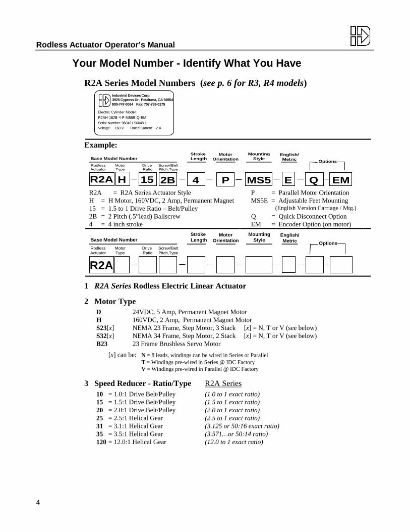
S42 Hybrid Step Motor Specifications
0.32
1.41/1.35
1.812
4-40UNF-2B THRU (2)4-40UNF-2B THRU (2)
0.2500
∅4.
28 M
AX
0.73±±0.03
0.2494
1/2-14NPS WIRE ENTRY
0.705/0.688
3.500 SQ REF
4.22 SQ MAX
∅0.6250/0.6245
ON A ∅4.950 B.C.
PILOT ∅2.188/2.184
∅0.29/0.27 THRU (4)
1.010/0.990
0.06
A ∅3.000 B.C. (3)Dp MIN, EQ SPACED ONDp MIN, EQ SPACED ON
10-32UNF-2B x 0.380.1875/0.1850
7.82[198.6]
Electrical DataS42T
(Series)S42V
(Parallel)Continuous Stall Torque oz-in [N-m] 1000 [7.1] 725 [5.1]Recommended Current/Phase Amps 6.0 7.9Winding Resistance @ Ambient Ohms .36 .09Inductance mH 7 1.75Max. Winding Temperature °F [°C] 212 [100]
Mechanical Data S42 (T/V)Rotor Inertia oz-in-s2 [kg-m2] 114×10-3 [80.5×10⁻⁵]Axial Shaft Load lbs [N] 65 [289]Radial Shaft Load - @ 0.5” lbs [N] 23.6 [105]Motor Weight lbs [kg] 19.1 [8.66]Step Angle (full step) degrees 1.8
Notes • Parallel (V) Wiring: 60% Duty Cycle Max. Above 5 rps (300 rpm).
• Always use at least 50% torque safety margin when applying step motors.
Motor Wiring
12 ft [3.7m] Wire Leads : S42N
A+BLACK
WHT/BLK
WHT/ORG
ORANGE
WHT/RED
RED
WHT/YEL
YELLOW
WHT/RED
WHT/YEL
RED
YELLOW
WHT/BLK
ORANGE
WHT/ORG
BLACK
SERIES CONNECTION PARALLEL CONNECTION
A- B-
B+
A-
B+
B-
A+
Quick-Disconnect : S42(T/V)
S6000 Drive Settings
Inductance
mH0
16
2440
8
48
56
32
Motor Current
Amps
Tenthsof Amps
0n/an/a
123
45
67
5
098
123
46
7
Inductance
mH0
16
2440
8
48
56
32
Motor Current
Amps
Tenthsof Amps
0n/an/a
123
45
67
5
098
123
46
7
S42T (Series) S42V (Parallel)
6.0 Amps 8* mH 4* mH7.9* Amps
*Drive setting closest to actual motor specifications.

Rodless Actuator Operator’s Manual
22
B23 Brushless Servo Motor Specifications
Electrical Data Mechanical DataContinuous Stall Torque oz-in [N-m] 161 [1.14] Rotor Inertia oz-in-s2 [kg-m2] 0.0019 [1.34 × 10⁻⁵]Cont. Torque at Rated Speed oz-in [N-m] 144 [1.02] Static Friction oz-in [N-m] 12.8 [0.09]Winding Resistance @ Ambient ohms 10.6 Dynamic Friction oz-in/kRPM [N-m/kRPM] 2.0 [0.01]Winding Resistance @ Tmax ohms 15.2 Thermal Resistance °C/W 1.07Inductance mH 16.1 Max. Winding Temperature °F [°C] 118 [155]Kt, Phase to Phase Peak oz-in/A [N-m/A] 57.6 [0.41] Mechanical Time Constant ms 0.684Kv Vp-p/kRPM 45.5 Axial Shaft Load lbs [N] 15 [65]Number of Poles 4 Radial Shaft Load @ 1/2 in lbs [N] 40 [180]Electrical Time Constant ms 1.769 Weight lbs [kg] 4 [1.8]
System Data with B8000 Series 110VAC 220VACMax. Speed RPM 3200 6500Drive Bus Voltage V 155 311Drive Peak Current A 8.3Ambient Temperature °F [°C] 77 [25]RMS Output Power W 288 355Nominal Peak Power W 353 1238Nominal Peak Stall Torque oz-in [N-m] 478 [3.38]
Motor Wiring

Options
23
B32 Brushless Servo Motor Specifications
Electrical Data Mechanical DataContinuous Stall Torque oz-in [N-m] 480 [3.4] Rotor Inertia oz-in-s2 [kg-cm2] 0.016 [1.13]Cont. Torque at Rated Speed oz-in [N-m] 400 [2.8] Static Friction oz-in [N-m] 12.8 [0.09]Winding Resistance @ Ambient ohms 3.4 Dynamic Friction oz-in/kRPM [N-m/kRPM] 2.0 [0.014]Winding Resistance @ Tmax ohms 5.1 Thermal Resistance °C/W 1.0Inductance mH 9.8 Max. Winding Temperature °F [°C] 310 [155]Kt, Phase to Phase Peak oz-in/A [N-m/A] 99.2 [0.70] 0 Ohm Damping oz-in/kRPM [N-m/kRPM] 2110 [14.9]Kv Vp-p/kRPM 77.8 Mechanical Time Constant ms 0.793Motor Constant oz-in/ W [N-m/ W ] 53.4 [0.38] Axial Shaft Load lbs [N] 25 [111]
Number of Poles 6 Radial Shaft Load @ 1/2 in lbs [N] 48 [214]Electrical Time Constant ms 2.837 Weight lbs [kg] 12 [5.4]
System Data with B8000 Series 110VAC 220VACMax. Speed RPM 1900 3800Drive Bus Voltage V 155 311Drive Peak Current A 10.0 10.0Ambient Temperature °F [°C] 77[25]RMS Output Power W 459 918Nominal Peak Power W 978 1957Nominal Peak Stall Torque oz-in [N-m] 853 [6.0]
Motor Wiring

Rodless Actuator Operator’s Manual
24
B41 Brushless Servo Motor Specifications
Electrical Data Mechanical DataContinuous Stall Torque oz-in [N-m] 864 [6.1] Rotor Inertia oz-in-s2 [kg-cm2] 0.0416 [2.94]Cont. Torque at Rated Speed oz-in [N-m] 768 [5.4] Static Friction oz-in [N-m] 16.0 [0.11]Winding Resistance @ Ambient ohms 3.6 Dynamic Friction oz-in/kRPM [N-m/kRPM] 8.0 [0.056]Winding Resistance @ Tmax ohms 5.4 Thermal Resistance °C/W 0.47Inductance mH 24.0 Max. Winding Temperature °F [°C] 310 [155]Kt, Phase to Phase Peak oz-in/A [N-m/A] 187 [1.32] 0 Ohm Damping oz-in/kRPM [N-m/kRPM] 7150 [50.5]Kv Vp-p/kRPM 148 Mechanical Time Constant ms 0.609Motor Constant oz-in/ W [N-m/ W ] 98.3 [0.69] Axial Shaft Load lbs [N] 50 [222]
Number of Poles 6 Radial Shaft Load @ 1/2 inch lbs [N] 110 [490]Electrical Time Constant ms 6.667 Weight lbs [kg] 20 [9.1]
System Data with B8000 Series 110VAC 220VACMax. Speed RPM 1000 2000Drive Bus Voltage V 155 311Drive Peak Current A 10.0 10.0Ambient Temperature °F [°C] 77 [25]RMS Output Power W 455 909Nominal Peak Power W 888 1770Nominal Peak Stall Torque oz-in [N-m] 1500 [10.6]
Motor Wiring

Options
25
5. OptionsDual Carriage (- D) Option (screw-driven actuators only)
The dual carriage option provides a second, non-driven carriage to better support larger loads, by increasingthe distance between support points. The second carriage is not attached to the leadscrew drive, but doesconnect to the internal bearing system. This allows field adjustment of the spacing between the twocarriages. Since the load is attached to both carriages, the second carriage will travel together with the first.

Rodless Actuator Operator’s Manual
26
Brake (-BS) OptionThe brake option provides an electrically released, spring-set, friction brake mounted to an extension of theleadscrew. It prevents backdriving when the unit is at rest, or in the case of a power failure.
Without power, the brake is engaged. Applying 115VAC releases the brake, allowing motion to occur.
Note: The brake option is used only for in-position holding, it should not be used for stopping a moving load more quickly.
Specifications R2A, R3 Series R4 SeriesMounting Location Leadscrew (see diagram below)Voltage 115VAC (to release)Current 0.11 Amps 0.14 AmpsHolding Torque 20 in-lbs 75 in-lbsCable Length 12 ft 12 ftHolding Force
Screw Type and Pitch Holding Force with -BS lbs [N]1B (1 Pitch Ballscrew) n/a 550 [2450]2B (2 Pitch Ballscrew) 240 [1100] n/a4B (4 Pitch Ballscrew) n/a 2200 [9790]5B (5 Pitch Ballscrew) 640 [2900] n/a5A (5 Pitch Acme Screw) 800 [3600] n/a6A (6 Pitch Acme Screw) 2400 [10700]
DimensionsR2A, R3 Series R4 Series
Cable: Dia 0.17 [4.3], 0.25R [6.4R] MINIMUM BEND RADIUS
DIA 2.96[75.2]
0.23
[5.8
]
0.60 [15.2]
1.00
[25.
4]
2.73 [69.3]
Right4.31
[109
.5]
45¡
2.16
[54.
7]
4.07 [103.5]
Rear
Strain Relief
Electrical Connections
Brake Coil AC
AC
+
–
Rectifier
115 VAC

Options
27
Encoder (-EM) OptionThe encoder option provides an incremental 500 line rotary encoder, factory mounted directly to the rearshaft of an IDC motor. The digital pulse output is used to provide position feedback to external devicessuch as motor controllers, counters, or PLC’s.
Note: 1. All encoders come with a 12ft [3.7m], 8 conductor (22AWG) cable. 2. Encoder cables can be extended up to a maximum of 200ft [60m].
SpecificationsOutput Type Incremental, TTL Level,
dual channel square wave.Differential Line Driver.
Pulses Per Revolution 500 line with quadrature(2000 PPR), One index pulse
Supply Voltage 5VDC+/-10%Current Requirements 80mA maxFrequency 100khz pre-quadrature, max
Dimensions
RIGHT
Cable: DIA 0.19 [4.8], 0.25R [6.4] MINIMUM BEND RADIUS
1.00 [25.4]
1.23 [31.1]
ENCODER
ENCODER COVER
DIA 3.10 [78.7]
DIA 2.16 [54.9]
T
LR
Electrical Connections
Ch Z+ (Yellow)
Ch Z- (Orange)
Ch B+ (Green)
Ch B- (Blue)
Ch A+ (Red)
Ch A- (Pink)
+5VDC (White)
GND (Black)
(Shield)

Rodless Actuator Operator’s Manual
28
6. Maintenance and TroubleshootingIDC Rodless Electric Linear Actuators are designed for maintenance-free operation over the service life ofthe product.
Periodic inspection and service can extend service life, especially under extreme operating conditions, suchas continuous high speed operation, shock loading, high speed stops/starts, or exposure to harshenvironments. In such applications, it is recommended that the screw and gears be re-lubricated, and aninternal inspection be completed periodically. Inspection/re-lube consists of partial disassembly, cleaning,visual evaluation, and re-lubrication.
Factory Repair ServiceIDC offers factory repair service for both in-warranty and out-of-warranty Electric Linear Actuators.Factory Service is the most reliable method of replacing damaged parts. In most cases, factory repair isquicker than field repairs, even considering shipping time. We return repaired units using the same shippingmethod as the unit was received by IDC, automatically decreasing turnaround time on urgent repairs.
Field Service / Lubrication / MaintenanceWhile we recommend our factory repair service for most customers, we recognize that occasionally it maybe necessary to perform minor repairs or maintenance in the field. Such cases include replacing accessibleworn or broken components such as belts or mounting hardware, and lubrication of leadscrew or gears asrequired. Actuators with certain options are more difficult to disassemble without special tools andinstruction, and these are noted in the table below in the Factory columns.
Parts can be ordered through your local IDC Distributor.
Note: Improper field assembly which causes damage or premature wear voids warranty.
Field Service ChartAll field service work should be done ONLY on authorized items, by qualified personnel.
Motor, Belt / Gear Speed Reducer Leadscrew / BeltAssembly
Mounting Options, Carriage,and Other Options
Maintenance Field• Gear Lubrication• Re-tension Motor Drive Belt
Field• Lubrication
Field• Clean External Surfaces
Conversion Factory• Belt / Pulley Ratios (1:1, 1.5:1, 2:1,
3:1 ratios)• Helical Gears (2.5:1, 3.1:1, 3.5:1,
5:1, 10:1, 12:1 ratios)
Authorized at FactoryOnly
Field• Motors
Factory
Repair Field• Motor Pulleys• Drive Belts• Gears - Motor Pinion - Intermed. Gear
Factory• Driven Pulley• Driven Gear• Driven
Coupling• BS Option
Authorized at FactoryOnly
Field• Motors• Mounting Options• Actuator Housing• Encoder• Quick Disconnect
Factory• -BS Option• 2.5, 3.1, 3.5, 5, 10 or
12 Drive Ratios
• Inline Coupling

Maintenance / Troubleshooting
29
LubricationRecommended Re-Lubrication Interval: Every 4 million inches [100km] of travel.
Example: An application which operates at a peak speed of 40”/sec each cycle will travel onemillion inches in 41.7 hours.
• 40 in/sec ÷ 1.5 = Average 26.7 in/sec (assuming 1/3-1/3-1/3 trapezoidal move profile)• 4,000,000 in ÷ 26.7 in/sec = 150,000 seconds ÷ 3600 sec/hr = 41.7 hours• This high speed application requires re-lubrication of critical components once every 41.7
hours of operation.
Component Lubricant Lubrication IntervalCarriage Seal IDC P/N 600-041, Silicone Grease 4 million inchesInternal Rail Bearing (R3/R4 Series Only)
IDC P/N 600-035, Lithium Grease 4 million inches
Leadscrew IDC P/N 600-025 for Ball screwsIDC P/N 600-022 for Acme screws
4 million inches
Leadscrew Thrust Bearings IDC P/N 600-035, Lithium Grease 4 million inchesHelical Gear Speed Reducer IDC P/N 600-035, Lithium Grease 4 million inches

Rodless Actuator Operator’s Manual
30
R2 Screw-Drive Exploded Parts Drawing

Maintenance / Troubleshooting
31
R2 Belt-Drive Exploded Parts Drawing

Rodless Actuator Operator’s Manual
32
R3/R4 Screw-Drive Exploded Parts Drawing

Maintenance / Troubleshooting
33
R3/R4 Belt-Drive Exploded Parts Drawing
Rodless Actuator Operator’s Manual
34
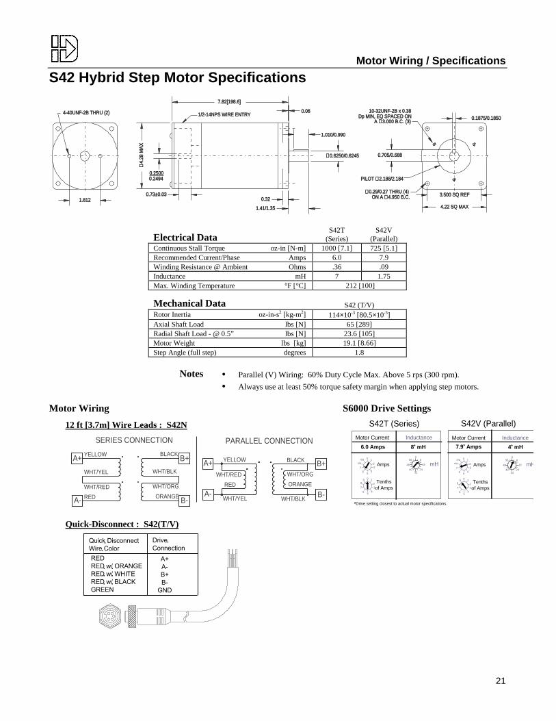
Troubleshooting ChartThe guide below offers assistance when troubleshooting basic actuator problems related to mechanicaloperation. When troubleshooting actuator performance, the cause may be related to the Drive/Motor usedwith the actuator. Refer to your IDC Control Manual for additional assistance on troubleshooting yourcontrol/actuator system.
Problems Related to...A. Audible Noise (emitting from actuator)B. Actuator MotionC. Positioning and Travel LengthD. Thrust TubeE. Actuator Parts and Options
A. Audible Noise (emitting from actuator)Symptom Cause1. Knocking, squealing or grinding during operation a) Excessive carriage loading
b) Carriage Bearing / Leadscrew needs re-lubricationc) Entry of foreign matter into actuator body
B. Actuator Motion1. Stalls/Binds/Sticks during a move (erratic motion) a) Load too great for actuator/motor
b) Pulley, gear, or coupling slippingc) Erratic motor/drive operationd) Drive nut or internal bearing seizing (locking up)
typically due to too high a duty cycle/temperature orentry of foreign matter into actuator
2. Extends when it should retract (and vice versa) a) Motor polarity reversed3. Vibrates during motion a) Motor Unstable (servo-gains, stepper-resonance)
b) Actuator being operated at or above critical speedc) Misalignment of internal components
4. Does not move at all when commanded to move a) Motor damaged, miswired, or wire looseb) Load too great for actuator/motorc) Problem with drive/motor
5. Does not move (or is erratic) although motor isrotating
a) Gear, pulley or coupling not secured to motor shaftb) Belt is loose or damagedc) Bad gear alignment or stripped teethd) Threads are stripped on the drive nut (Acme)
6. Not running at rated speed a) Load is too great for desired speedb) Limited by critical speed (oscillation) of screwc) Incorrect screw pitch or drive ratiod) Actuator option (i.e. bronze drivenut) causing
excessive friction
C. Positioning and Travel Length1. Actuator backdriving (without holding torque on
motor)
a) Backdriving force generated by load is greater than thestatic holding capacity of the actuator
b) Excessive external vibration2. Actuator backdriving (with holding torque on the
motor)a) Backdriving force generated by load is greater than the
holding capacity of the screw/nut of the actuator andthe holding torque of the motor
b) Loss of motor holding torque (servo and steppers)3. Not enough travel a) Position sensors reducing “actual” travel
b) Actuator option (may be limiting stroke)c) Excessive side-loadingd) Customer mounting (physically limiting travel)
Maintenance / Troubleshooting
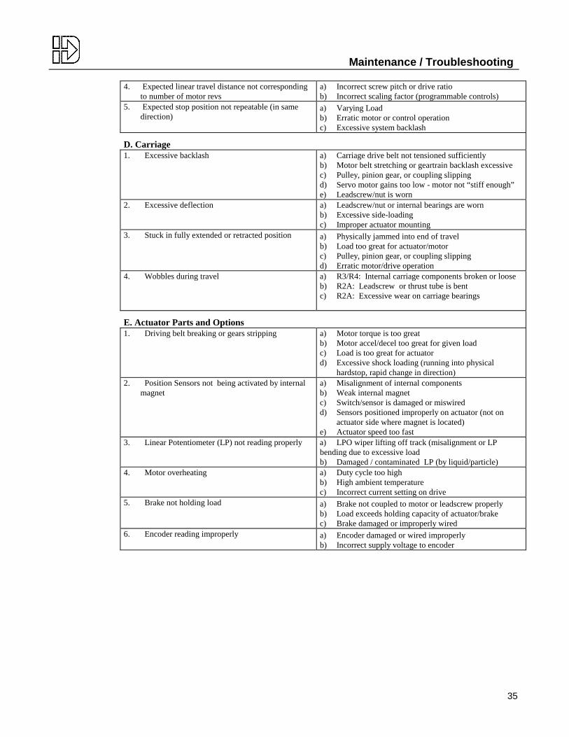
35
4. Expected linear travel distance not correspondingto number of motor revs
a) Incorrect screw pitch or drive ratiob) Incorrect scaling factor (programmable controls)
5. Expected stop position not repeatable (in samedirection)
a) Varying Loadb) Erratic motor or control operationc) Excessive system backlash
D. Carriage1. Excessive backlash a) Carriage drive belt not tensioned sufficiently
b) Motor belt stretching or geartrain backlash excessivec) Pulley, pinion gear, or coupling slippingd) Servo motor gains too low - motor not “stiff enough”e) Leadscrew/nut is worn
2. Excessive deflection a) Leadscrew/nut or internal bearings are wornb) Excessive side-loadingc) Improper actuator mounting
3. Stuck in fully extended or retracted position a) Physically jammed into end of travelb) Load too great for actuator/motorc) Pulley, pinion gear, or coupling slippingd) Erratic motor/drive operation
4. Wobbles during travel a) R3/R4: Internal carriage components broken or looseb) R2A: Leadscrew or thrust tube is bentc) R2A: Excessive wear on carriage bearings
E. Actuator Parts and Options1. Driving belt breaking or gears stripping a) Motor torque is too great
b) Motor accel/decel too great for given loadc) Load is too great for actuatord) Excessive shock loading (running into physical
hardstop, rapid change in direction)2. Position Sensors not being activated by internal
magneta) Misalignment of internal componentsb) Weak internal magnetc) Switch/sensor is damaged or miswiredd) Sensors positioned improperly on actuator (not on
actuator side where magnet is located)e) Actuator speed too fast
3. Linear Potentiometer (LP) not reading properly a) LPO wiper lifting off track (misalignment or LP bending due to excessive loadb) Damaged / contaminated LP (by liquid/particle)
4. Motor overheating a) Duty cycle too highb) High ambient temperaturec) Incorrect current setting on drive
5. Brake not holding load a) Brake not coupled to motor or leadscrew properlyb) Load exceeds holding capacity of actuator/brakec) Brake damaged or improperly wired
6. Encoder reading improperly
a) Encoder damaged or wired improperlyb) Incorrect supply voltage to encoder

Rodless Actuator Operator’s Manual
36
Replacement Parts List for R2A Series Actuators
Replacement parts can be ordered through your local IDC Distributor.
R2AD24V Brushed DC
R2AH160V Brushed DC
R2AS232.3” Stepper
R2AB23Brushless Servo
Motor D MotorD Inline
810-101830A302
H MotorH Mtr. w/Quick Disc.
820-213820-214
S23N/T/V InlineS23T ParallelS23V ParallelS23N Parallel
801-123801-223-T801-223-V801-223
B23 MotorB23-BM Motorw/ brakeB23A Motor
810-023810-023B
810-025Brushes Brush Set
(for 810-101 only)810-199 Brush Set, H 820-298
Cables 12’ Quick Disc.(3-lead)
QF1-12 12’ Quick Disc.(3-lead)
QF1-12 12’ Quick Disc.(5-lead)
QF3-12 12’ B23 / B23-BM(includes leads for
–BM brake)
QBB2-12optional
Drive TrainPulleys
1:1 15 tooth, motor15 tooth, leadscrew
851-122A850-123A
15 tooth, motor15 tooth, leadscrew
858-115A850-123A
15 tooth, motor15 tooth, leadscrew
872-015A850-123A
1.5:1 12 tooth, motor18 tooth, leadscrew
851-118A850-120A
12 tooth, motor18 tooth, leadscrew
858-112A850-120A
12 tooth, motor18 tooth, leadscrew
872-012A850-120A
2:1 10 tooth, leadscrew20 tooth, leadscrew
851-119A850-121A
10 tooth, leadscrew20 tooth, leadscrew
855-130A850-121A
10 tooth, leadscrew20 tooth, leadscrew
872-010A850-121A
Motor Belt 901-106K Motor Belt for all 1:1, 1.5:1, 2:1 ratiosGear Sets3.1, 3.5:13.5:1 Pinion
Int. GearLeadscrew Gear
950B001950-035950-015
3.1:1 PinionInt. GearLeadscrew Gear
950J031950-035950-015
3.5:1 PinionInt. Gear
950D002950-035
3.1:1 PinionInt. Gear
950J031950-035
12:1 PinionUpper ClusterLower ClusterLeadscrew Gear
950K001950K051950K052950K011
N/A PinionUpper ClusterLower ClusterLeadscrew Gear
950K102950K051950K052950K011
N/A
InlineCoupling
Motor AdapterSleeveLeadscrew Adapter
950-019950-021U950-020
Motor AdapterSleeveLeadscrew Adapter
950-024950-021U950-020
Motor AdapterSleeveLeadscrew Adapter
950-019950-021U950-020
Motor AdapterSleeveLeadscrew Adapter
950-024950-021U950-020
CarriageSeal Strip 661-201 Ordered by the foot (i.e. Qty 6 = 6 feet)
To calculate required seal length: Add 10 to stroke in inches, divide by 12 to get feet of seal required.Example: 36” stroke R2A actuator – Seal Length (ft) = [ 36 inches + 10 ] ÷ 12 = 3.8 ft of seal required (order 4 ft.)
Seal RollerAssembly
517-007103F150517-005
Seal Roller (Two required per carriage)Seal Roller Dowel Pin (Two required per carriage)Roller Bracket Flat Spring (Two required per carriage)
SlidingBearings
518-001 R2 Carriage Bearing (Eight required per carriage) **not required on R2A updated roller bearing design
TransportBelt
518R501 Ordered by the foot (i.e. Qty 12 = 12 feet)To calculate required belt length: Multiply stroke in inches by 2, add 24, divide by 12 to get feet.Example: 36” stroke R2A actuator – Belt Length (ft) = [ 36 inches × 2 + 24 ] ÷ 12= 8 feet of belt required
Lubrication 990-002600-025600-035600-041
Lubrication Packet for Acme Screws (12.5 oz grease gun cartridge)Lubrication Packet for Ballscrews (one packet per 36 inches of stroke)Lubrication Packet for Gears, Leadscrew Thrust Bearings (12.5 oz grease gun cartridge)Lubrication Packet for Carriage Seal (1 oz container, up to 108 inches of stroke)
Encoder E1KIT Encoder Assembly Kit

Maintenance / Troubleshooting
37
Replacement Parts List for R3 Series ActuatorsReplacement parts can be ordered through your local IDC Distributor.
R3D24V Brushed DC
R3H160V Brushed DC
R3S232.3” Stepper
R3S333.4” Stepper
R3B23Brushless Servo
Motor D Motor(2 leads)
830A302 H Motor w/Quick Disc.
Fitting
820-214 S23 Motor(8 leads)
801-123 S33N MotorS33T MotorS33V Motor
801-133-N801-133-T801-133-V
B23 MotorB23-BM Mtrw/ brakeB23A Motor
810-023810-023B
810-025Brushes lifetime rated Brush Set, H 820-298
Cables N/A(attached to motor)
12’ QuickDisc.
(3-lead)
QF1-12 N/A(attached to motor)
12’ QuickDisc.
(5-lead)
QF3-12 12’ B23 & B23-BM
(includesfor optional
brake)
QBB2-12
leads–BM
Drive TrainPulleys
1:1 15 th, motor15 th, screw
858-115A850-123A
15 th, motor15 th, screw
851-122A850-123A
15 th, motor15 th, screw
858-115A850-123A
15 th, motor15 th, screw
858-128A850-123A
15 th, motor15 th, screw
872-015A850-123A
1.5:1 12 th, motor18 th, screw
858-112A850-120A
12 th, motor18 th, screw
851-118A850-120A
12 th, motor18 th, screw
858-112A850-120A
12 th, motor18 th, screw
858-129A850-120A
12 th, motor18 th, screw
872-012A850-120A
2:1 10 th, motor20 th, screw
855-130A850-121A
10 th, motor20 th, screw
851-119A850-121A
10 th, motor20 th, screw
855-130A850-121A
12th, motor24th, screw
858-129A850-126A
10 th, motor20 th, screw
872-010A850-121A
Motor Belt Motor Belt 901-112K Motor Belt 901-112K Motor Belt 901-112K Motor Belt 901-117 Motor Belt 901-112KGear Sets
5:1 Pinion GearUpper Clust.Lwr ClusterBushingLdscrw. Gear
955R002955S001950S002750P002950T001
Pinion GearUpper Clust.Lwr ClusterBushingLdscrw. Gear
955R001955S001950S002750P002950T001
Pinion GearUpper Clust.Lwr ClusterBushingLdscrw. Gear
955R002955S001950S002750P002950T001
Pinion GearUpper Clust.Lwr ClusterBushingLdscrw. Gear
955R003955S001950S002750P002950T001
Pinion GearUpper Clust.Lwr ClusterBushingLdscrw. Gear
955R001955S001950S002750P002950T001
10:1 Pinion GearUpper Clust.Lwr ClusterBushingLdscrw. Gear
950R002950S001950S002750P002950T001
Pinion GearUpper Clust.Lwr ClusterBushingLdscrw. Gear
950R001950S001950S002750P002950T001
Pinion GearUpper Clust.Lwr ClusterBushingLdscrw. Gear
950R002950S001950S002750P002950T001
Pinion GearUpper Clust.Lwr ClusterBushingLdscrw. Gear
950R003950S001950S002750P002950T001
Pinion GearUpper Clust.Lwr ClusterBushingLdscrw. Gear
950R001950S001950S002750P002950T001
InlineCoupling
Mtr. AdapterSleeveScrew Adapt.
950-019950-021U950-020
Mtr. AdapterSleeveScrew Adapt.
950-024950-021U950-020
Mtr. AdapterSleeveScrew Adapt.
950-019950-021U950-020
Mtr. AdapterSleeveScrew Adapt.
950-022950-021U950-020
Mtr. AdapterSleeveScrew Adapt.
950-024950-021U950-020
CarriageSeal Strip 661-201 Ordered by the foot (i.e. Qty 6 = 6 feet)
To calculate required seal length: Add 11 to stroke in inches, divide by 12 to get feet of seal required.Example: 36” stroke R3 actuator -- Seal Length (ft) = [ 36 inches + 11 ] ÷ 12 = 3.9 ft of seal required (order 4 ft.)
Seal RollerAssembly
517-007103F150517-005
Seal Roller (Two required per carriage)Seal Roller Dowel Pin (Two required per carriage)Roller Bracket Flat Spring (Two required per carriage)
TransportBelt
516R501 Ordered by the foot (i.e. Qty 12 = 12 feet)To calculate required belt length: Multiply stroke in inches by 2, add 26, divide by 12 to get feet.Example: 36” stroke R3 actuator -- Belt Length (ft) = [ 36 inches × 2 + 26 ] ÷ 12= 8.2 ft of belt required (order 9 ft.)
Lubrication 990-002600-025600-035600-041
Lubrication Packet for Acme Screws (12.5 oz grease gun cartridge)Lubrication Packet for Ballscrews (one packet per 36 inches of stroke)Lubrication Packet for Gears, Rail Bearing Blocks, Leadscrew Thrust Bearings (12.5 oz grease gun cartridge)Lubrication Packet for Carriage Seal (1 oz container, up to 108 inches of stroke)
Encoder E1KIT Encoder Assembly Kit

Rodless Actuator Operator’s Manual
38
Replacement Parts List for R4 Series ActuatorsReplacement parts can be ordered through your local IDC Distributor.
R4H160V Brushed DC
R4S333.4” Stepper
R4S424.2” Stepper
R4B323.3” Brushless Servo
R4B415” Brushless Servo
Motor H4 Motor w/Quick Disc.
Fitting
810-106 S33N MotorS33T MotorS33V Motor
801-133-N801-133-T801-133-V
S42N MotorS42T MotorS42V Motor
801-142-N801-142-T801-142-V
B32 MotorB32 w/ brake
801-032801-032B
B41 MotorB41 w/ brake
810-041810-041B
Cables 12’ QuickDisc.
(3-lead)
QF1-12 12’ QuickDisc.
(5-lead)
QF3-12 12’ QuickDisc.
(5-lead)
QF3-12 12’ B3212’ B32 brk
QFB3-12QBB3-12
12’ B4112’ B41 brk
QFB3-12QBB3-12
Drive TrainPulleys
1:1 30 th, motor30 th, screwMotor Belt
864-102873-102901-108
30 th, motor30 th, screwMotor Belt
869-102873-102901-108
30 th, motor30 th, screwMotor Belt
864-102873-102901-108
30 th, motor30 th, screwMotor Belt
870-102873-102901-108
30 th, motor30 th, screwMotor Belt
864-102873-102901-108
1.5:1 24 th, motor36 th, screwMotor Belt
864-101873-101901-108
24 th, motor36 th, screwMotor Belt
869-101873-101901-108
24 th, motor36 th, screwMotor Belt
864-101873-101901-108
24 th, motor36 th, screwMotor Belt
870-101873-101901-108
24 th, motor36 th, screwMotor Belt
864-101873-101901-108
2:1(no tensioner)
24 th, motor48 th, screwMotor Belt
864-101873-103901-109
24 th, motor48 th, screwMotor Belt
869-101873-103901-109
24 th, motor48 th, screwMotor Belt
864-101873-103901-109
24 th, motor48 th, screwMotor Belt
870-101873-103901-109
24 th, motor48 th, screwMotor Belt
864-101873-103901-109
3:1 16 th, motor48 th, screwMotor Belt
869-103873-103901-109
16 th, motor48 th, screwMotor Belt
867-003873-103901-109
Gear Sets5:1 Pinion Gear
Upper Clust.Lwr ClusterLdscrw. Gear
944-23LH946-051H946-052H943-52RH
Pinion GearUpper Clust.Lwr ClusterLdscrw. Gear
945-23L946-051H946-052H943-52RH
Pinion GearUpper Clust.Lwr ClusterLdscrw. Gear
944-23LH946-051H946-052H943-52RH
Pinion GearUpper Clust.Lwr ClusterLdscrw. Gear
945B23LH946-051H946-052H943-52RH
Pinion GearUpper Clust.Lwr ClusterLdscrw. Gear
944-23LH946-051H946-052H943-52RH
10:1 Pinion GearUpper Clust.Lwr ClusterLdscrw. Gear
944-19LH946-101H946-102H943-52RH
Pinion GearUpper Clust.Lwr ClusterLdscrw. Gear
955-19LH946-101H946-102H943-52RH
Pinion GearUpper Clust.Lwr ClusterLdscrw. Gear
944-19LH946-101H946-102H943-52RH
Pinion GearUpper Clust.Lwr ClusterLdscrw. Gear
945B19LH946-101H946-102H943-52RH
Pinion GearUpper Clust.Lwr ClusterLdscrw. Gear
944-19LH946-101H946-102H943-52RH
InlineCoupling
Coupl. Ass’y 950-100 Coupl. Ass’y 950-106 Coupl. Ass’y 950-100 Coupl. Ass’y 950-107 Coupl. Ass’y 950-100
CarriageSeal Strip 661-201 Ordered by the foot (i.e. Qty 6 = 6 feet)
To calculate required seal length: Add 11 to stroke in inches, divide by 12 to get feet of seal required.Example: 36” stroke R4 actuator -- Seal Length (ft) = [ 36 inches + 12 ] ÷ 12 = 4.0 ft of seal required (order 4 ft.)
Seal RollerAssembly
517-007103F150517-005
Seal Roller (Two required per carriage)Seal Roller Dowel Pin (Two required per carriage)Roller Bracket Flat Spring (Two required per carriage)
TransportBelt
517R501 Ordered by the foot (i.e. Qty 12 = 12 feet)To calculate required belt length: Multiply stroke in inches by 2, add 33, divide by 12 to get feet.Example: 36” stroke R4 actuator -- Belt Length (ft) = [ 36 inches × 2 + 33 ] ÷ 12= 8.75ft of belt required (order 9 ft.)
Lubrication 990-002600-025600-035600-041
Lubrication Packet for Acme Screws (12.5 oz grease gun cartridge)Lubrication Packet for Ballscrews (one packet per 36 inches of stroke)Lubrication Packet for Gears, Rail Bearing Blocks, Leadscrew Thrust Bearings (12.5 oz grease gun cartridge)Lubrication Packet for Carriage Seal (1 oz container, up to 108 inches of stroke)
Encoder E1KIT Encoder Assembly Kit
Maintenance / Troubleshooting
39
Warranty and Service CoverageIndustrial Devices Corporation warrants all R Series Actuators to be free of defects in material &workmanship for a period of one year from the date of shipment to the user. Products returned prepaid tothe factory will be repaired or replaced at our option at no charge, and returned prepaid to the user.
Products that have expended their useful life after one year or have been improperly used or damaged, in theopinion of Industrial Devices, are not subject to the terms of this warranty.
Technical SupportIndustrial Devices offers technical support through its factory authorized and trained Distributors, andthrough its factory-based Applications Engineering and Inside Sales department.
If an application problem exists or if the product has failed, contact your Distributor or Industrial Devicesfor technical assistance. Contact our factory at 1-800-747-0064, outside the U.S. at 707-789-1000.
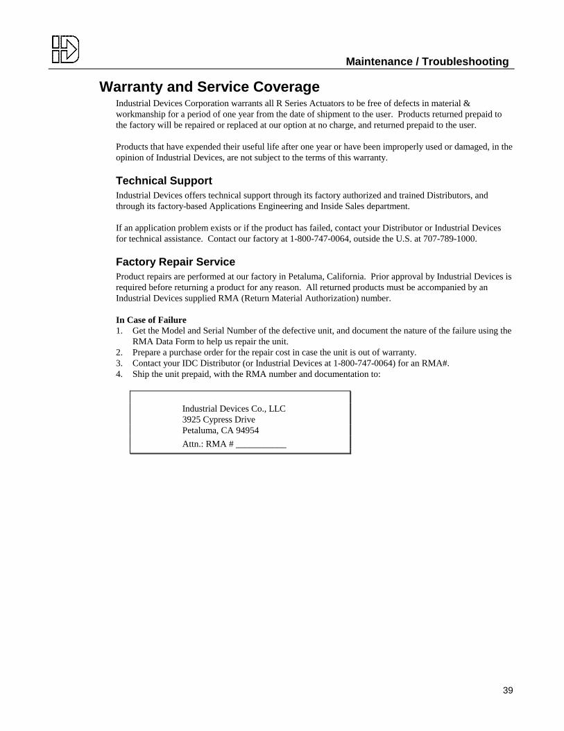
Factory Repair ServiceProduct repairs are performed at our factory in Petaluma, California. Prior approval by Industrial Devices isrequired before returning a product for any reason. All returned products must be accompanied by anIndustrial Devices supplied RMA (Return Material Authorization) number.
In Case of Failure1. Get the Model and Serial Number of the defective unit, and document the nature of the failure using the
RMA Data Form to help us repair the unit.2. Prepare a purchase order for the repair cost in case the unit is out of warranty.3. Contact your IDC Distributor (or Industrial Devices at 1-800-747-0064) for an RMA#.4. Ship the unit prepaid, with the RMA number and documentation to:
Industrial Devices Co., LLC3925 Cypress DrivePetaluma, CA 94954
Attn.: RMA # ___________


INDUSTRIAL DEVICES CO., LLC3925 Cypress Drive • Petaluma, CA USA 94954(800) 747-0064 • Fax (707) 789-0175OUTSIDE THE U.S. CALL (707) 789-1000Internet: http://www.idcmotion.comE-mail: [email protected]
R Series Operator’s Manual PCW-4647 Jul-99