Embed Size (px)
Citation preview

R1A6 071 FUNDAMENTAL STUDIES OF LASER INTERACTION IN MUTERIAUS 1/PREPRATION: NEW AS.. CU) BROWN UNIV PROVIDENCE RI DIVOF ENGINEERING T F MORES MAR 94 RFOSR-TR-86-9054
UNCL ASSIFOSR-FOS-936623F/O7/3 NL
EmhhmhhhhmhEE

- j
U36
1.25 .1 1.
lMICPt- SHTO TS HR

AD-A 16 071REPORT DOCUMENTATION PAGE1b. RESTRICTIVE MARKINGS
2& SECURITY CLASSIFICATION AUTHORITY 3. OISTRIBUTION/AVAI LABILITY OF REPORT
ICATON/OWNGRDINGSCHEULEAppr'oved for publ I@ relesegi92. DECLASSIFIAINOWGAN SHDL d4a5riu..dL.. Uteo"0
4PERFORMING OR4GANIZATION REPORT NUMBER(Sl 5. MONITj, A IO g~R Nd.b.
6.NAME OF PERFORMING ORGANIZATION I. OFFICE SYMBOL 7s. NAME oF MONITO ING ORGANIZATION 9Brown University j(it plcbe AFOSR
ow. ADDRESS (city, State and ZIP Code) 7b. ADDRESS (City, State and ZIP Code)APIDivision of Engineering Building 410Brown University Boiling AFB, DC 20332-6448
* Providence, Rhode Island 02912 ______________________
ft NAME OF FUNOIN;ISPoNSORING &b.OFFICE SYMBOL 9. PROCUREMENT INSTRUMENT IDENTIFICATION NUMBER* ORGANIZATION (fapplicable)
AFOSR J NP AFOSR-83-0632ft ADDRESS 1C01y. State and ZIP Code) 10. SOURCE OF FUNDING NOS.
Building 410 PROGRAM PROJECT TASK WORK UNIT*Boiling AFB, DC 20332-6448 ELEMENT NO. NO. NO. NO.
________________________________ 61102F 2301 Al N/A11. TITLE (include Security Clasuification) "t FUNDAMENTAL STUDIESIF LASER INTERACTION IN MATERIALS PIXPARATION:
*NEW ASPECTS OF CHEMICAL VAPOR DEPOSITION, TP CHLOROSILANEj LITERATU JE SURVEY AND COMBUSTIO N"12. PERSONAL AUTHOR(Sl
T F. Mores TO.1.PG ON1TYPE OF REPORT 13b. TIME COVERED 14. DA = T(Y.H
*FINAL FR0F4~j3L9]O T08LQj 37~16. SUPPLEMENTARY NOTATION
17. COSATI CODES 1S. SUBJECT TERMS (Continue on reerse if necessry and identify by block number)FIELD GROUP SUB. GPR.
19. ABSTRACT (Continue on rev~erse it necessay and identify by block numlierp
Various properties and reactions of trichorosilane (SiHC1')hv ensude ooti
information on the combustion of trichlorosilane. Th~ inare absorption spectra, impacflammability results and the heat of formation of Si l are included in this paper. The
S production of silicon from trichlorosilane by thermal decomposition and h drogen-:~.~ reduction is reviewed to point out certain reaction characteristicso SiC'I. The corn-
bustion of trichlorosilane is studied in detail. Two reactions are proposed as being theLUJ combustion and are as follows.
20. OISTRIOUTIONIAVAiLASILITY OF ABSTRACT 121. ABSTRACT SECURITY CLASSIFICATION
* UNCLASSIFIEOIUNLIMITED SAME AS RPT. OTIC USERS 0 UNCLASSIFIED22L NAME OF RESPONSIBLE INDIVIDUAL 1 22b. TELEPHONE NUMBER 22c. OFFICE SYMBOL
HOWARD R. SCHLOSSBERG 1202/767-4906 NP
* 00 FORM 1473, 83 APR EDITION OF I JAN 73 IS OBSOLETE. UNCLASSIFIEDSECURITY CLASSIFICATION OF THIS PAGE

"-054 -
NposR. R 8 6iO 5
Final Report
to the
Department of the Air ForceAir Force Office of Scientific Research (AFSC)
AFOSR/NM, Building 410Bolling Air Force BaseWashington, DC 20332
For the Grant AFOSR-83-0632
FUNDAMENTAL STUDIES OF LASER INTERACTION IN MATERIALSPREPARATION: NEW ASPECTS OF CHEMICAL VAPOR DEPOSITION,TRICHLOROSILANE, LITERATURE SURVEY AND COMBUSTION EX-PERIMENTS
Period Covered: September 1983 to March 1984
from . I
Division of Engineering .Brown University •
Providence, Rhode Island 02912 - ;,.
- -- L "
"" -
Report prepared by:Approyod for Publ I& rojeags,istribution unlimited
" .'.-° I
, 1- ._ _ _ _
T. F. Morse* Cr oetProfessor of Engineering Executive OfficerPrincipal Investigator Division of Engineering
*C. Cunkelman, M.Sc."*1- _
*1-

ABSTRACT
Various properties and reactions of trichorosilane (SiHCl 3 ) have been studied to obtain
information on the combustion of trichlorosilane. The infrared absorption spectra, impact
flammability results and the heat of formation of SiHCI3 are included in this paper. The
production of silicon from trichlorosilane by thermal decomposition and hydrogen reduction
is reviewed to point out certain reaction characteristics of SiHCI3 .
The combustion of trichlorosilane is studied in detail. Two reactions are proposed as
being the combustion reaction and are as follows.
[ ) 5SiHCI3 + 02 -- >5SiO2 + HCI + 70l2 + 2H20; (4)+ '" -..._.,SiHCl +0 > SiO + HCI + CI + .-
1fL3 2 J 2 O~ 2 Tl.d~ 2 J
CHaving no basis on which to determine which of the two reactions is the actual combustion
reaction, both are considered in this paper. The theoretical heat of combustion for reaction
1 is .815.3 callg and for reaction 2 is -774.9 cal/g. Combustion experiments were
performed with trichlorosilane using a Parr semimicro calorimeter. The amount of SiHCI3
lost by evaporation between the time the sample was weighed and ignited was estimated.
Using this corrected mass value, the heat of combustion of trichlorosilane was found to be
-803.8 cal/g, which tends to indicate that reaction 1 above, dominates.
'prolC x rThis toolrni .0 ~,,' IIeLstrlb*Tio I .t-.. Dl vi"tI S
* iii. - ;;
+~~..... ...... .. _..._ ...... .......... ..... .. . . . .

CONTENTS
ABSTRACT.
Chapter page
L. INTRODUCTION.......................
HI. LITERATURE SURVEY....................2
General Properties.....................2Absorption Spectra.....................3Silicon Production......................6Impact Flammibility...............................17Standard Heat of Formation.. .... .... .... .... .. 18The Combustion Reaction .. .... .... .... .... ..... 19
4II. HEAT OF COMBUSTION. ... .... .... .... .... .... 20
Theoretical Heat of Combustion. ... .... .... .... .... 20Experimental Heat of Combustion. ... .... .... .... .. 21
The apparatus and its operation.. .... .... .... .. 21The Experiment. .... .... .... ... .... ..... 25Results and Discussion .. .... .... .... .... .... 27
IV. CONCLUSIONS......................3
REFERENCES..........................7
iv.-

LIST OF FIGURES .6i
Figure page .
1. IR absorption spectra of SiHCI3 . .................... 3.'.,, -
2. I pcmo SiHC13 liqui rat .s S. deoito r e. . .""- .......
3. S I 3 e r v Si vapo . ....................... 4..
4. Temperature vs. rEquilibgri Deompsi ationfs.Hl . . . . . . . . . . .1 7-.-...
8. Temp. vs. moles of SiHCI3 decomp, reaction products. .. .. .. .. ... 11 ,-..
S9. Mol ratio of H 2 to SiHCI3 vs. SiHCI3 reacts. .. .. .. .. .. .. ... 12 .
10. H 2 to SiHCI3 tool ratio vs. SiHCI3 react. ratio. ............. 13 '"
11. The SiHCI3 and H 2 reaction mechanism. . .. .. .. .. .. .. ..... 14 "- ,
12. The bomb head with fuse and sample in place .. .. .. .. .. .. . .. 23
13. Corrected temperatures for SiHCI3 Run 1 . .. .. .. .. .. .. . .. 32
-€14. R esults of the 3 SiH C I3 calorim eter runs . . . . . . . . . . . . . . . . 33"- •
Iv -
°o
-. . :
I.
".,. .._ . ,., ., .-, ...-'., .,.2. . ctu of .iCI liqui......... ... .. .... . ... .,,,...- ...... _ '._. . . . . .
€:-.. ';. .'. 6 . SiHl 3 feed rate vsC .. S yil......... -..................... 8

LIST OF TABLES
Table page
1. Properties of SiHC13. . . . . . . . . . . . . . . . . . . . . . 2
2. Molecular vibration frequencies of SiHCI 3. . . . . . . . . . . . . . . .
3. Heats of Formation.... .... .... .... .... ... .... .. 21
4. Results of Standardization Runs .. ... .... .... ... .... .... 29
5. Results from the SiHCI 3 CaoieeRus.............3
r
-7.~

WIT-CC
H Chapter I'V4INTRODUCTION
Interest in the combustion properties of trichlorosilane arose during research aimed at
improving the existing methods of preparing glass preforms that can be drawn into optical
fibers. Currently, the reaction of silicon tetrachloride with oxygen is used in particle
deposition processes to obtain optical fiber grade silicon dioxide.
SiCI4 + 2 ... > SiO 2 + 2C12
Although the combustion of silicon tetrachloride is an exothermic reacion, the reaction
does not proceed until the temperature of the reactants reaches 12000 C. As a possible
alternative to this reaction for producing silicon dioxide, we wish to consider the
( substitution of silicon tetrachloride by trichlorosilane. This provides the motivation for our
literature survey into the various physical properties of trichlorosilane and for our
examination of the heat of reaction of trichlorosilane with oxygen. The combustion of
trichlorosilane is an exothermic reaction and readily occurs at low temperatures when
initiated by a spark or heat lamp. Based on information in the literature [2, 14], the
combustion of trichlorosilane proceeds according to one of the following reactions.
5SiHCI 3 + 02 ---- > 5SiO 2 + HCl + 7C 2 + 2H 2 0 (1)
SiHCI3 + 02 ---- > SiO 2 + HCI + Cl 2 (2)
• ..J.
o/%
Chapter II
LITERATURE SURVEY
Unfortunately, there is little information in the literature on the oxidation of
trichlorosilane, SiHCl 3 . Various reactions are proposed for the combustion reaction oftrichlorosilane, and they are discussed in this section. The production of pure silicon is the
most common application in which trichlorosilane is used. Various techniques utilizing
thermal decomposition and hydrogen reduction of SiHCl 3 are employed to obtain pure
silicon. Some of these processes are described later in this section in an effort to point out
certain reaction characteristics of trichlorosilane. Additional information is available on
the general properties, absorption spectras, impact flammibility, and heat of formation of
trichlorosilane and is incorporated into this section.
2.1 GENERAL PROPERTIES
Trichlorosilane is a clear, flammable liquid with a suffocating odor. It is also highly
volatile and corrosive which makes it very difficult to handle. Table 1 lists the properties of
trichlorosilane as given in the Alfa Catalogue [1].
A °
TABLE 1
Properties of SiHCI3
Molecular Weight 135.45Liquid -
Melting Point -126.50 CBoiling Point 33o C at 758mmDensity 1.34 g/cmRefractive Index 1.402C
-2-
3
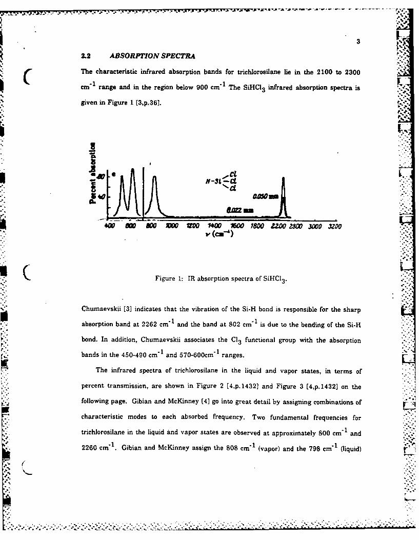
2.2 ABSORPTION SPECTRA
The characteristic infrared absorption bands for trichlorosilane lie in the 2100 to 2300I1cm"I range and in the region below 900 cm"I The SiHCI3 infrared absorption spectra is
given in Figure 1 [3 ,p. 3 6 ].
is"
( -=4W w Soo 00 4W 100 z 78 £Z = aX 30 U00
Figure 1: IR absorption spectra of SiHCI3 .
Chumaevskii [3] indicates that the vibration of the Si-H bond is responsible for the sharp
absorption band at 2262 cm"1 and the band at 802 cm" is due to the bending of the Si-H
bond. In addition, Chumaevskii associates the Cl 3 functional group with the absorption
bands in the 450-490 cm "1 and 570-600cm " ranges.
The infrared spectra of trichlorosilane in the liquid and vapor states, in terms of
percent transmission, are shown in Figure 2 [4 ,p.143 2 1 and Figure 3 [4,p.1432] on the
following page. Gibian and McKinney (4] go into great detail by assigning combinations of - 1
characteristic modes to each absorbed frequency. Two fundamental frequencies for
trichlorosilane in the liquid and vapor states are observed at approximately 800 cm "1 and
2260 cm" . Gibian and McKinney assign the 808 cm"1 (vapor) and the 798 cm"' (liquid) r
5,. (
[- ,, . -. - ... . . • . . -
-. . . . - . .-- .-. .. '. '..--. .. ', ...'.. .. -. -. .- '.. . ".. -. .- ' i .' '. -'. .' .': -- ..' .- , '. -.,. .'. ..,.-'--,..' . .S.

4
bands to the Si-H bending mode. The 2274 cm' 1 (vapor) arnd the 2258 cm"'(iqi) ad
are attributed to the vibration of the Si-H bond. It should be noted that Gibian and
McKinney's work was the only found in which the infrared absorption spectra of liquid
trichlorosilane was given.
No.o~sm
A-0.3mm
ow0 flop10 1300 8600 1700 2000 2400 2000 300 400 I5000
WAVE OUNSMEN
Figure 2: IR spectrum of SiHCI3 liquid.
L SAwn-. 2ACMu,. sem-I Romi 0m-, 10*0.O-ISLIT 3 1 l U
Vf A- 660mmA SiHCIS * nIm-zPlacaSUnIR C- 30m
41 cuese3 M 0- 10mm
1r 900 1100 .1300 SOC r700 WO0 2400 29W0 S000 4000 500
- . **. . .WAVE NUMORR
Figure 3: IR spectrum of SiHCI 3 vapor.

5
Shimanouchi's Table of Molecular Vibrational Frequencies (5) for gaseous
trichorosilane provides a list of each mode and its associated infrared absorptionCT rfrequency. In addition, the Raman spectra of liquid trichlorosilane is included in this table.
The letter code after the selected frequency value is an indication of the accuracy of the
value. The letters run from A to E. The letter code after the infrared frequency gives an
estimate of the intensity of the band. VS indicates very strong, S indicates strong while M
indicates medium. And finally, the code after the Ramam frequency indicates whether the
shift is due to a polarized or depolarized electron state. A copy of this table is included as
Table 2 [5,p. 1028).
TABLE 2
Molecular vibration frequencies of SiHCl3
( Approximate SelectedNo.- type of mode value of Infrared Raman
frequency
cm - 1 cm-' cm - -
(Gas) (Liquid)V, SiH stretch. 2261 B 2260.9 S 2258 p
V 2 SiCI1 s-stretch. 499 B 498.6 S 489 pV. SiCl s-deform. 254 B 253.7 M 250 p -V Sill bend. 811 B 810.8 VS 799 dpV5 SiCl d-stretch. 60{) B 600.1 VS 587 dpV, SiCI, d-deform. 176 B 175.5 M 179 dp
Little information is available concerning the absorption of SiHCI 3 in the ultraviolet or
visible range. Nagata, Dohmara, Fujita, Oka and Taniguchi [6] studied particle formation
',." ''o.:.'
[,2 .. ,2 a. • .-.. ..2 ...g.-.......... 2.. .... _..... ..... ...... ... ....... ..............
*x~~~~~~*-~~J -.. 9 W-. -. V -.. F;-~--.-.v-' ' '-
7I
6
from gas phase silicon compounds including SiHCI3 by light or electron irradiation.
Photo-irradiation was performed using a 500W xenon lamp or a 500W high pressureIC I-
mercury lamp. Electron irradiation was done with 10MeV electrons from a linear
accelerator. It was found that trichlorosilane did not absorb light from the xenon or
mercury lamp. Particle formation from trichlorosilane was observed only after electron
beam irradiation. Clearly, more work must be done to completely determine and
understand the absorption characteristics of SiHCI3 in the ultraviolet and visible spectras.
2.3 SILICON PRODUCTION
According to the literature, the most common application of trichlorosilane is the.+ ...
production of high purity silicon. Silicon deposition from the thermal decomposition of
trichlorosilane occurs at temperatures above 4800 C [7). The yield of silicon, expressed as
a percent, is defined as the ratio of the weight of silicon gained to the total weight of silicon
atoms in the trichlorosilane used, multiplied by a factor of 100. Blocher, Browning and
Wilson [8] show that the yield of silicon from the thermal decomposition of trichlorosilane
is temperature sensitive. Figure 4 [8,p.1521 on the following page shows that at
atmospheric pressure the greatest yields of Si occur from 9000 C to 11000 C. Within this
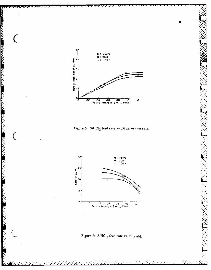
temperature range, Yoshizawa, Hashino and Sakaguchi [7] studied the rate of deposition
and the yield of silicon in relation to the feeding rate of trichlorosilane. Figure 5 [7,p.6]
shows the relationship of the feed rate of trichlorosilane to the deposition rate of silicon at
9500 C, 10000 C and 11000 C. Figure 6 [7 ,p. 7 ] gives the relationship between the yield of
silicon and the feed rate of trichlorosilane. From all three figures, the conclusion can be
made that both the silicon deposition rate and the silicon yield are maximum at 10000 C.
A method commonly used to increase the yield of silicon from trichlorosilane is
hydrogen reduction. While hydrogen reduction increases the yield of silicon per gram of
SiHCl3 the addition of hydrogen reduces the concentration of SiHCI3 . Therefore, to3r,
maintain a high deposition rate while increasing the yield. the feed rate of trichlorosilane
. . . . .. .. . . . . . ° ° . • . . . °.. . . . . . . o , o , • , k o
.... _..-................__. ...

9. . .-
7
24
-22,-2 21 -
z 20
Figure 4: Temperature vs. Equilibrium Decom-position of SiHC 3-,C
must increase. However, if the feed rate of trichlorosilane is increased too much, the yield
of silicon begins to decrease. A detailed description of the hydrogen reduction process and
the effects of hydrogen reduction and other parameters on silicon production are given
later in this section.
Based on the observation that silicon is produced during the thermal decomposition of
trichlorosilane, Yoshizawa, Hashino and Sakaguchi [7] looked into the possibility that
silicon deposition from the thermal decomposition of SiHCl 3 without any added reductants
could be a feasible way of producing silicon. They proceeded by examining the reaction
products in an effort to understand the equilibrium composition and the reaction methods
involved. For reaction temperatures greater than 7000 C, a glass reactor was used
"'-. equipped with tungsten wire or tantalum foil connected to electrodes on the reactor top for ..
heating the reaction gas. The walls of the glass reactor were cooled and maintained at
/%
. . . . . . . .. . . .. . . . .". *. *- * • •* o.:. -...- :.,. .. - ... .... .. ...... ... < : , .. .. , *.. ..., .- ..** .,,5.:, . ,.., - - ., .- _
8
0 9501CU: '000.
-
0[
L0.7
4--
o;! 0. 4 6 O LO Z -
Figure 6: SiHHl3 feed rate vs. Si deoieinlt.
3C3

9
%600 C. For reaction temperatures less than 7000 C, a quartz reactor was used and an
electrical furnace outside the reactor was used to heat the trichlorosilane. The silicon
deposited on various surfaces during the reaction, on the tungsten wire or tantaium foil in
the glass reactor and on the inside wall of the quartz reactor.
H 2 , SiH 4 , and unreacted SiHCI3 appear in significant amounts in the gaseous product
of this decomposition. When the decomposition occurs at temperatures greater than
8500 C, gaseous HCl is also produced in significant amounts. In addition, Yoshizawa,
Hashino and Sakaguchi [7] reported finding a transparent, oily liquid inside the glass
reactor which turned into a white solid when coming into contact with air. This liquid
product is assumed to be a mixture of higher molecular weight compounds of silicon and
chlorine which thermally decompose into Si and SiCl 4. The polymerizing reactions they "
believe produce this transparent. oily liquid are as follows.
2 SiHCI3 ... > Si 2CI6 + H2
6SiHCI 3 ..-- > 2Si3 CI8 + 2 H, + 2 HCI
By analysing the composition of the equilibrium mixture in the reactor, Yoshizawa, %
Hashino and Sakaguchi [7] propose that the thermal decomposition proceeds according to
the following simultaneous reactions.
4SiHCI3 .-- > 3SiCl4 + Si + 2H 2 (1) F'--.
2 SiHCI3 .... > SiCl4 + Si + 2 HCI (2)
SiHC13 .... > SiCI2 + HCI (3)
Assuming that these are the three significant reactions, the equilibrium constant for each
is found and the extent of each reaction as a function of temperature is determined [7].
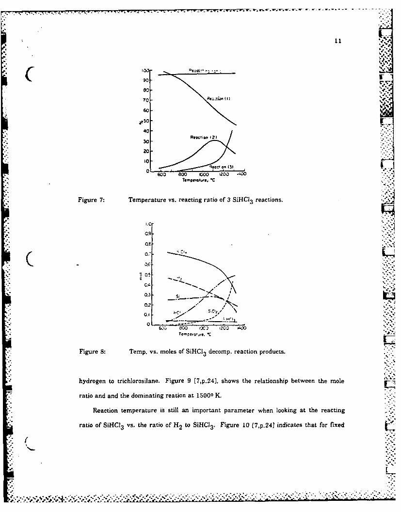
Figure 7 [7,p.17] shows that although the extent of each individual reaction varies with
N.(
"'-". - '.","--'.L .' -.-- ," "-. '- -- ,':,- ,' -',- '" ' " " . ... "

10
temperature, the thermal decomposition of trichlorosilane which is the sum of the three
( reactions listed above goes almost to completion over the temperature range from 6000 C
to 14000 C. Since silicon is not produced in the third reaction, there is clearly a point of
maximum silicon yield within the 6000 C to 14000 C temperature range. As previously
shown, the point of maximum silicon yield occurs at approximately 10000 C. Figure 8
[7,p.17] on the following page indicates that the yield of silicon starts to decrease at
temperatures greater than 10000 C. Yoshizawa, Hashino and Sakaguchi (7] attribute this ....
to the formation of silicon dichloride and other higher molecular silicon and chlorine
compounds at high temperatures.
The conversion ratio of trichiorosilane to high purity silicon by thermal decomposition
is found to be very low. Blocher, Browning and Wilson [8] find that the maximum silicon
yield is approximately 23 percent, occuring in the 9000 C to 10000 C temperature range.
(Refer to Figure 4' Based on similar findings, Yoshizawa, Hashino and Sakaguchi [7]
conclude that the thermal decompositon of trichlorosilane alone is not an efficient way of
C producing silicon. They attribute this low conversion rate to the number of reactions
involved and their complexities. Therefore, hydrogen reduction of trichlorosilane must be '-'..,
used to produce pure silicon in high yield. .
The hydrogen reduction of trichlorosilane takes place according to the following
reaction.
SiHCI3 + H 2 --.- > Si + 3HCl
Yoshizawa, Hashino and Sakaguchi [7] define the reacting ratio of trichlorosilane as the ..
ratio of reacted SiHCI 3 to the amount of SiHCI 3 initially present. It is found that the , ...
reacting ratio of SiHCI3 increases as r, the mole ratio of H 2 to SiHCI3 increases [7]. At
low values of r, the dominant reactions are the thermal decomposition reactions. At values
of r equal to or greater than 10, hydrogen reduction becomes the dominant reaction.
Therefore, high purity silicon can be produced in high yield by increasing the mole ratio of
Ir~i~:., i:.i.;,'....- ?.? .-d.?,,-'.-:.i '.--.c..",.-.,-/-;.---/ -> ....................-..-......-...........-...... ,-. ..., . .,....***.*,
-- V~. -. -- -
"-011
0%7
80 . .--.
so--70"
60-
40-Reaction (2)
30i
20-
10-R. ca on (31.
0600 800 i0O L200 J00""
Tempurature, *C
Figure 7: Temperature vs. reacting ratio of 3 SiHC13 reactions.
* 0.9.
0.7.
-C 0.0-
CA
02 < 02,
*,. 0.2 '-S-
0-800 X , i.,- Ae C
Figure 8: Temp. vs. moles of SiHCI3 decomp. reaction products.
hydrogen to trichlorosilane. Figure 9 [7,p.241, shows the relationship between the mole
ratio and and the dominating reation at 15000 K.
Reaction temperature is still an important parameter when looking at the reacting
ratio of SiHCJ3 vs. the ratio of H2 to SiHC13. Figure 10 [7,p.2 41 indicates that for fixed
([
/..'.." '.:. *,% A' '.'.%',.'..'.. '';..'.,'.';. '.L.-':'..',.'..".''.' .'','',''. .'.-, ' ".'.." ...,'_Z_.Z%":-'-,' : ': ': .k'C_-._:,-..'--.- _, .- --'

12
) 4SNCI- 3 5;CI4 S;?, %"
C ) 2S.c, 3-S.C;.+S *-2 eC-
4- SiHCI,3 SCj+ MCI
.. ... .. ..
Z
E
,' -' ,,' -C
-- 't0 20 2We roto 0 Mj to SoMCIl
Figure 9: Mol ratio of H2 to SiHCI 3 vs. SiHCI3 reacts.
values of r, the reacting ratio of trichlorosilane increases with temperature. Figure 9 and 7.
Figure 10 show that at 15000 K a SiHCI 3 reacting ratio of close to 100 percent can be .C..
achieved for a minimum mole ratio of H 2 to SiHCI3 of 15. It appears that for a high
enough ratio of H 2 to SiHC13 and at a high enough temperature, a 100 percent yield of
silicon is theoretically possible. Clearly, there must be a tradeoff in this case. The silicon
deposition rate decreases as the hydrogen to trichlorosilane ratio increases. As previously
shown, it is possible to increase the deposition rate by increasing the SiHCI 3 feed rate.
The balance between the feed rate, deposition rate, hydrogen to trichlorosilane ratio and
reation temperature must be made based on economic considerations.
Silicon deposition from trichlorosilane is usually a combination of thermal
decomposition and hydrogen reduction. Nishizawa and Saito [9] used infrared absorption
spectroscopy to study the reaction mechanisms of silicon chemical vapor deposition from
thermal decomposition and hydrogen reduction with SiHCl3 as the source material. The3rexperiment involved feeding a mixture of SiHCl 3 and H 2 through a hot walled horizontal
.
r
N... .

13
.1007
90-9(8
0 10 Z- . C 4C0 t.. t- 90 '00
Figure 10: H2 to SiHCl3 mol ratio vs. SiHCI3 react. ratio.
reactor. Both direct IR spectroscopy and IR spectroscopy by the sample method were used
to determine the silicon-hydrogen-chlorine reactants present during the process. The
following reactants were observed: SiCI4 , SiHCI3 , SiH CI2 HCI, SiCI3 n SC 2
Nishizawa and Saito [9] conclude that silicon chemical vapor deposition from
trichlorosilane in an hydrogen atmosphere at temperatures in the 8000 C to 12000 C range
proceeds according to the following reactions.
SiHCI 3 --- > SiCI2 +Hl
SiHC13 + H 2 ... > SiHCI2)
SiH2 Cl2 ---> SiCI2 + H2 [
2i2I--+----> Si(s) + 2 HCl
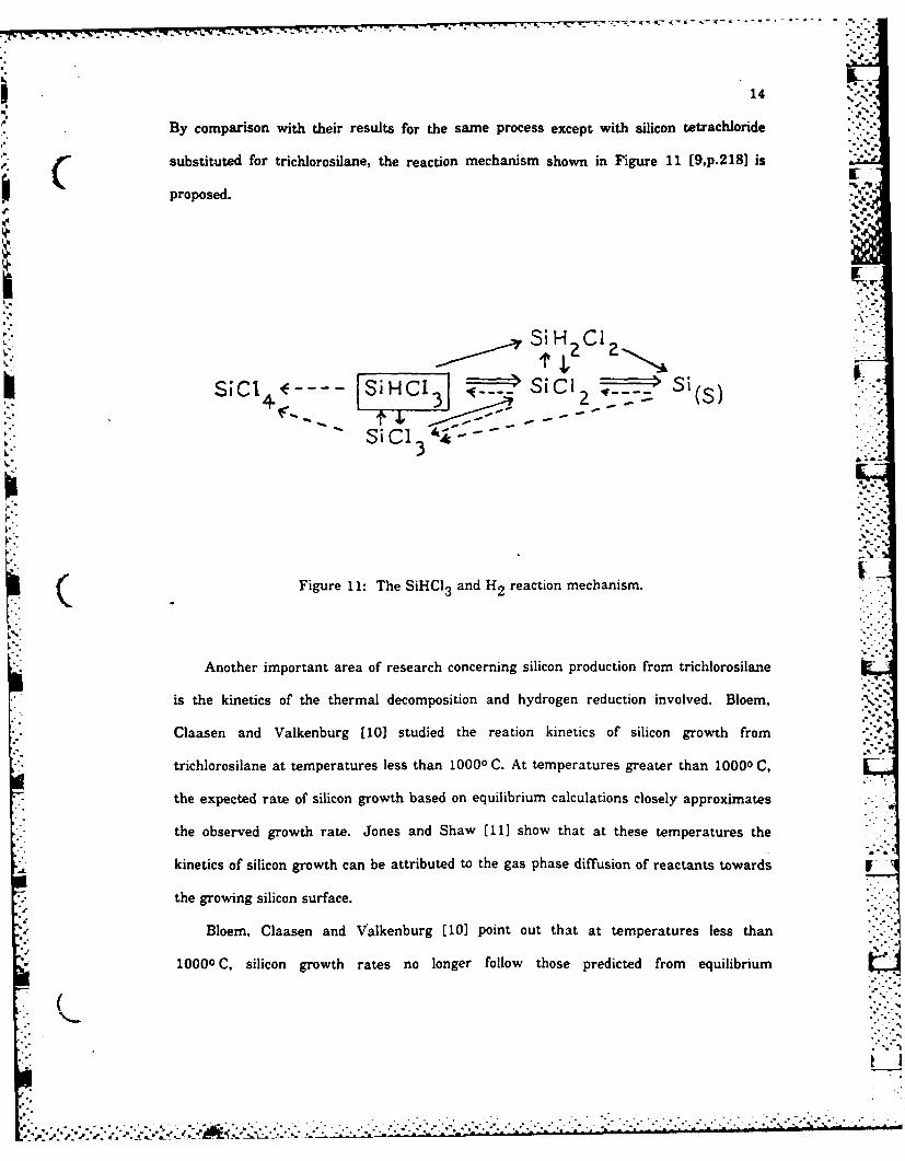
By comparison with their results for the same process except with silicon tetrachloride
00' substituted for trichlorosilane, the reaction mechanism shown in Figure 11 [9,p.218] is
proposed.
, -
r
~~Si
H CI
"
41.
- - C1SIC13
Figure 11: The SiHCI 3 and H2 reaction mechanism.
Another important area of research concerning silicon production from trichlorosilane
is the kinetics of the thermal decomposition and hydrogen reduction involved. Bloem,
Claasen and Valkenburg (101 studied the reation kinetics of silicon growth from
trichlorosilane at temperatures less than 10000 C. At temperatures greater than 10000 C,
the expected rate of silicon growth based on equilibrium calculations closely approximates
the observed growth rate. Jones and Shaw (11] show that at these temperatures the
kinetics of silicon growth can be attributed to the gas phase diffusion of reactants towards V
the growing silicon surface.
Bloem, Claasen and Valkenburg [10) point out that at temperatures less than
( 10000C, silicon growth rates no longer follow those predicted from equilibrium
., .-
~ -. ?,"
.S_
4
. . . . .. . . . . . . . . . . . . . . . . . . .

15
calculations. They propose that at lower temperatures, the rate of surface reations
decrease and the surface reactions become the rate limiting step. By analogy with their
previous study on the kinetics of silicon growth from SiH 2CI 2 [12), Bloem, Claasen and
Valkenburg assume that SiCl4 is the main surface species in the growth of SiHCI3 as it4 3
-
was in the case of SiH 2 CI2 . Since SiCl2 reduces to silicon in the presence of hydrogen, it V.
is expected that the growth rate of silicon from SiHCI3 at temperatures less than 10000 C
is a function of hydrogen partial pressure.
Bloem, Claasen ans Valkenburg [10] tested their proposal experimentally by studing
silicon growth from SiHCI 3 using SiHCI3 -H2 -N2 as the reacting mixture in a horizontal
reactor operating at atmospheric pressure. Studies were done at 8000 C, 9000 C and
10000 C, and at various hydrogen partial pressures. Silicon growth occured on top of a thin . .
silicon layer on a substrate that was placed in the reactor. Again, the results showed that
the silicon growth rate increases with increasing hydrogen pressure and was greatest at
10000 C. The proposed reaction steps for silicon deposition in the presence of hydrogen at
temperatures less than 10000 C are as follows [101. Kr
SiHCI3 ....> SiCI 2 + HC"
SiC12 + surface site --- > SiCI2 (adsorbed)
SiC 2 + H 2 ....> Si(s) + 2HCI
The SiHC13 undergoes a gas phase reaction which produces SiC12 and HCh This is
followed by the SiCl 2 adsorption on the silicon surface and the reduction of SiCl 2 by
hydrogen to Si and HCL. As expected from these reaction steps, the addition of HCl to the
gas phase decreases the silicon growth rate. Based on their findings, Bloem, Claasen and
Valkenburg [10] propose the following step as the rate limiting step in the silicon vapor
deposition from trichlorosilane at temperatures less than 10000 C.
++• :- ,, SiCl 2 + H2 ... > Si(s) + HCI'x
16
Finally, Blocher, Browning and Wilson [8] take the process of silicon production from
trichlorosilane one step further by proposing that a closed-cycle regeneration system be
used. Their suggested regeneration system consists of two reactors, the decomposer and
the regenerator. Silicon is produced in the decomposer. Since the volume of the S.
decomposer is fixed and the rate of SiHCI3 feed is restricted by the reaction times
involved, the advantage of adding hydrogen to the reacting SiHCl3 is insignificant. The
optimum operating condition in this case appears to be one in which the reaction gas
composition is 100 percent SiHCI3 . Therefore, Blocher, Browning and Wilson [8] study the
possibility of producing pure silicon by the thermal decomposition of trichlorosilane and in
turn of converting the SiCI4 by-product back into SiHCl 34 3
As shown by Hunt and Sirtl [13] and Yoshizawa, Hashino and Sakaguchi (71 the
major silicon containing products in equilibrium with the silicon produced by the thermal
decomposition or hydrogen reduction of trichlorosilane at temperatures in the 9000 C to
11000C range are SiCl 4 (g), SiHCI3 (g) and SiCl 2 (g). Additional species present in
C significant amounts are HCI(g) and H2 (g). The SiCl 2 tends to react with the HCI present
to produce SiHCl 3 . Therefore, the major by-products of the reaction are SiC4, H2 and
HCI. Unreacted SiHCI and small quantities of SiH 2 CI2 and SiHCI3 are also found in the
equilibrium mixture. The SiH 2 Cl2 and SiC13 are converted to SiCl 4 and SiHCI3 through
arbitrary reactions with HCI. The SiHCI 3 is then separated out for direct recycling while
the SiCl4 is regenerated into SiHCI3
In the regenerator, SiCl4 , HCI and H2 are placed in contact with a bed of granular
metallurgical grade (MG) silicon and two important reactions occur.
Si(MG) + SiCl4 (g) ---- > 2 SiCl2 (g)
2 SiCl2 (g) + 2 HCI(g) ---- > 2 SiHCI3 (g)
Vg~
t 1
.' . . . . . .. . . . . . . . ... .. ... .. . . - . . . .. -. . .. . ...
77. .- - 7-: :
17
Blocher, Browning and Wilson [8] attempt to find ways to control these reactions in an
effort to maximize the production of SiHCI 3 and minimize the production of SiC 4 .
To achieve the desired balanced cycle, the HCI is separated out of the SiCI4 -H 2 -HCI
mixture and is added later to quench the reversal of SiCl 2 to SiCI4 by converting the SiC!2
into SiHCI3 . The SiCI 4 and H2 are fed through a bed of metallurigical grade silicon. The
desired regenerative process is one in which the operating temperatures are minimized, the
amount of metallurgical grade silicon used is minimumized while the yield of SiHCI3 is
maximized. It has been found that by adding the correct amount of hydrogen to the silicon
tetrachloride, the process can be controlled such that one mole of metallurgical grade
silicon is added to the system in the regenerator for each mole of high purity silicon
produced from the SiHCI 3 without excess production of SiHCl 3 or SiCI4. It is also found
that within the 11270 C to 13270 C range, decreasing the operating temperature of the
regenerator requires an increase in the moles of SiCl 4 and H, used in order to maintain a
constant yield of SiHCI3 . The regenerative process is not found to be efficient atIC temperatures less than 11270 C.
Based on these results, it appears that by imposing the correct parameters such as
temperature and the H2 to SiCI4 ratio, this cLosed-cycle chlorosilane system has the . "
potential of being an efficient, economical process for producing high purity silicon.
2.4 IMPACT FLAMMIBILITY
A mixture of trichlorosilane and air will explode when initiated by a spark, a heat rod or
possibly, ultraviolet light [2]. In addition, Muller, Witte and Bever [14] found that SiHCI3explode on impact if enough SiH 2 CI2 is added to the SiHCI3 . An explosion is initially
observed in a mixture containing 25 percent SiH 2 CI2 and 75 percent SiHCI3 . The
SiH 2Cl 2 -SiHCI3 mixture must contain 25 percent or more SiH 2 CI2 for an explosion to
occur. Some of the older literature on the explosiveness of SiHCI3 is given in Gmelins
Handbuch der anorganischen chemie [2). Certain results indicate that these earlier
samples may have contained some of the more reactive SiH 2 Cl 2.
" I.
................................................ i...
.~ d - . ..-

18
2.5 STANDARD HEAT OF FORMATION
In 1972, Hunt and Sirtl [13] of Dow Corning Corporation calculated the standard heat of
formation of gaseous trichlorosilane as part of an effort to determine species concentrations
in various equilibrium Si-H-Cl systems. The enthalpy of formation of SiHCl 3 was derived
from already existing experimental data. It had been found that the equilibrium molar
ratio of SiCl 4 to SiHCl3 is highly sensitive to the heat of formation of SiHCl3 used in the
calculation when assuming a fixed heat of formation value for SiCl4 . In addition, it was
known that a relatively simple equilibrium exists in the Si-H-Cl system at low
0temperatures. At temperatures below 1250 K, the gas phase equilibrium mixture contains
only SiCI4 SiHCI3 HCI and H2 . All the enthalpy values are known with substantial
certainty except that-of SiHCI3 . Hunt and Sirtl [13] also studied decomposition reactions of
trichlorosilane and silicon tetrachloride , hydrogenation of trichlorosilane and chlorosilane
formation resulting -rom silicon hydrochlorination to arrive at a heat of formation value for
trichlorosilane. They conclude that the standard heat of formation of SiHCI3 is
-116.0 0.7 kcallmol.
In 1981, Bell, Perkins and Perkins [15] of Simon Fraser University in Canada
calculated the heat of formation of various chlorosilanes in the gaseous phase including
SiHCI3 . Their calculation was based on using the heats of formation of SiH4 and SiCl4
given in the 1972 CATCH Tables for Silicon Compounds to find the corresponding heats of
atomization and then deriving the bonding parameters for the Si-H bond and the Si-Cl
bond. The heat of formation calculated by Bell, Perkins and Perkins for trichlorosilane by
this method is -482.4 kJ/mol or -115.3 kcal/mol.
A significant amount of data was used to derive both Hunt and Sirtl's [13], and Bell,
Perkins and Perkins' [15] enthalpy of formation values for trichlorosilane. The
-116.9±0.7 kcal/mol is based purely on experimental data while the -115.3 kcal/mol value
is based on experimental and theoretical correlations. Having no basis upon which to
conclude that one method is far superior to the other , the average value of the two, -116.1
kcal/mol, will be used in this work.
.'............................................. ....... . .- .:.,.,,.'..' -'. -' -' -' -' . . . . . . .-• • . .. --. * . . , . o . , . . . . . . . - - - - - . -_ _ ' ,- ' -
19
2.6 THE COMBUSTION REACTION
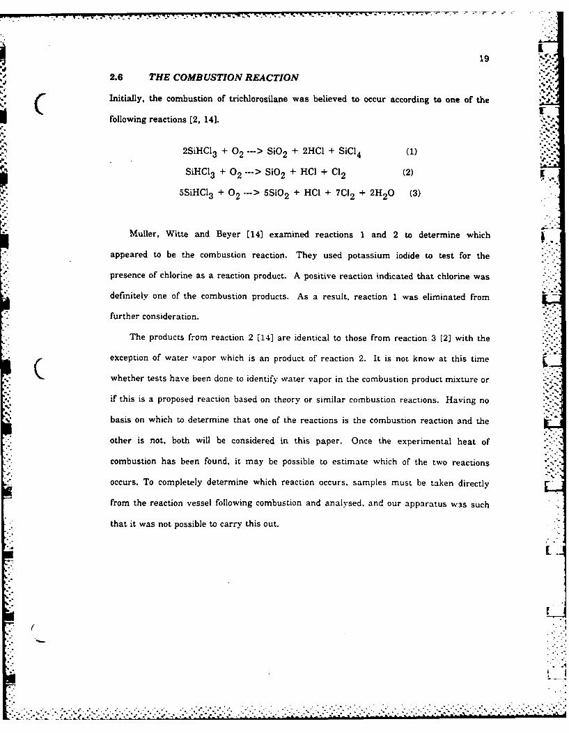
Initially, the combustion of trichlorosilane was believed to occur according to one of the
following reactions [2, 141.
2SiHCl3 + 02 ---> SiO2 + 2HCI + SiCl 4 (I)
SiHCI3 +0 2 ---> SiO2 + HCI + Cl 2 (2)
5SiHCl 3 + 02 ---> 5Si0 2 + HCl + 7C%2 + 2H 2 0 (3)
"--
Muller, Witte and Beyer [14) examined reactions I and 2 to determine which
appeared to be the combustion reaction. They used potassium iodide to test for the
presence of chlorine as a reaction product. A positive reaction indicated that chlorine was
definitely one of the combustion products. As a result, reaction 1 was eliminated from
further consideration.
The products from reaction 2 [14] are identical to those from reaction 3 [2) with the
exception of water vapor which is an product of reaction 2. It is not know at this time
whether tests have been done to identify water vapor in the combustion product mixture or
if this is a proposed reaction based on theory or similar combustion reactions. Having no
basis on which to determine that one of the reactions is the combustion reaction and the
other is not, both will be considered in this paper. Once the experimental heat of
combustion has been found, it may be possible to estimate which of the two reactions
occurs. To completely determine which reaction occurs, samples must be taken directly
from the reaction vessel following combustion and analysed, and our apparatus was such
that it was not possible to carry this out.
I
S.
Chapter III
HEAT OF COMBUSTION
3.1 THEORETICAL HEAT OF COMBUSTION
The theoretical heat of combustion of trichlorosilane is calculated from the heat of
formation value of each reactant and product as found in the literature. Again, the
following reations are being considered.
Reaction 1:
5SiHCI3 (1) + 60 2 (g) --> 5SiO 2 (s) + HCIg) + 7C12(g)
+ 2H,0(g)
Reaction 2:
SiHCI3 (1) + 0 2(g)-> SiO 2 (s) + HClg) + Cl 2ig)
The literature gives the heat of formation (Aho f) of SiHCI 3 in the gaseous phase only.
As described in the previous section, two slightly different heats of formation were found
for gaseous SiHCI3 [15, 13). The value used in this paper of -116.1 kcal/mol is the
average of the two.
To proceed with calculating the theoretical heat of combustion for each of the above
reactions, the heat of vaporization of SiHCI 3 must be determined. Unfortunately, no
information is avaiable that gives the vapor pressure of trichlorosilane as a function of
temperature. Resorting to an alternate approach, Trouton's Estimation Method [16] is
employed to estimate the heat of vaporization of SiHCl 3 . Trouton discovered that the ratio
between the heat of vaporization and the normal boiling point of a liquid is approximately
constant, 2lcal/molO K. This is a good approximation for non-polar molecules.
- 20-
.7 -

21
-hvap I Boiling point = 21 cal/molO K.
From the Airco Catalogue [171, the boiling point of SiHCI3 at atmospheric pressure is F
89.40 F (31.80 C). The corresponding heat of vaporization for SiHCI3 is 6.4 kcal/mol. This3°
gives the heat of formation of liquid SiHCI 3 as -122.5 kcallmol The standard heats of
formation of all reactants and products in the two proposed trichlorosilane combustion
reaction are given in the following table.
TABLE 3
Heats of Formation
compound Aho f(kcallmol) Reference
SiHCI3 (g) -122.5 above0"(g) 0 18 "'-"Si,9(s, quartz) -205.4 18
-'- H C ITg> -22.063 is . :Clo(g) 0 18 5--H (g -57.798 i
Based on the above data, the theoretical heat of combustion for reaction 1 is -110.43
kcat'mol or -815.3 calig and for reaction 2 is -104.96 kcal/ mol or -774.9 cal/g.
3.2 EXPERIMENTAL HEAT OF COMBUSTION
3.2.1 The apparatus and its operation
A Parr 1421 semimicro calorimeter was used to determine the heat of combustion of
SiHCI 3 . Additional accessories required for the operation of the calorimeter were a strip
chart recorder, a tank of oxygen, and a chemical balance. The semimicru calorimeter
consists of a glass Dewar reaction chamber, a semimicro bomb, a thermistor probe and
"". temperature measurement bridge, all arranged to operate in a single compact cabinet.
Connections are provided at the thermometer panel on the top face of the calorimeter
-.. . . . . . .....-.. . . . . .

22
cabinet for connecting the strip chart recorder. The thermistor probe and temperature
measurement bridge are designed such that the temperature rise is plotted directly in
degrees Celcius on the strip chart recorder for temperature in the ten degree span from
200 C to 300 C.
Samples are burned in the stainless steel semimicro bomb. The bomb is designed to
hold and burn samples that range approximately from 0.02 to 2.0 grams and release not
more than 1200 calories. The sample is placed in the sample holder, and its net weight is
recorded. Then, it is placed in the support loop located off the support post on the|Iunderside of the bomb head as shown in Figure 12 below.
Fuse wire, 10 cm. in length, is attached to the two hook terminals on the underside of
the bomb cover. Using a small Allen wrench, the wire loop is rotated into a helical coil in
order to concentrate the heat on the sample. The electrical connection to this fuse is made
by pressing the ignition terminal down onto the terminal nut located on the bomb head.
The sample is ignited by passing an electrical current through this coiled fuse wire. Figure
12 has been reproduced from the Parr calorimeter catalogue [20,p.8.1 and shows the bombU Chead with the fuse and sample in place.
Once the sample is placed on the support loop and the fuse wire is attached, the bomb
head is placed on the bomb cup and body and is held together by tightening the bomb
screw cap with a wrench. When tightly clamped together, the bomb is ready for the
oxygen fill procedure. An oxygen fill connection is provided with the semimicro calorimeter
allowing the bomb to be filled from a commercial oxygen tank. The gas inlet valve located
on the bomb cover is opened and closed by means of a pin wrench inserted through the eye
of the valve cap. (refer to Figure 12) The bomb is filled with oxygen by opening the bomb
valve, pressing the oxygen fill coupling over the valve cap and slowly opening the needle
valve in the fill line until the desired pressure is reached.
At this point, the bomb contains air which if not removed will affect the heat of
combustion results. To remove the air from the bomb, the bomb is alternately filled with
~~~~............................. ,........-............... ....,.........-,--." " °" " " • - - -. •. .' . .-
- .' - . " . . . . . . . . . ..- "- •. . ...-

23
.' .'J" *"
.- Figure 12: The bomb head with fuse and sample in place. .
-, ~~oxygen to 30 atmospheres and exhausted back to ambient pressure. This purging cycle is .- ':
' ': repeated four consecutive times prior to the final oxygen fill to 30 atmospheres.
" ~After the final fill, the ignition connection is placed over the terminal nut on the bomb ":
"-" ~cover and the pressurized bomb is placed in the bomb support loop and hung from the rim ]:'
"" of the glass Dewar reaction chamber. The Dewar chamber contains 400 grams of water.,.
The temperature of the water used in this experiment is slightly lower than room "'-,
temperature. The glass Dewar reaction chamber rests inside a highly polished, stainless.,"-"
steel air can. The air can is designed so that it is unable to absorb or emit any radiant
heat, and sits inside a foamed plastic block in the calorimeter cabinet. These three layers ::-
serve as an isothermal jacket around the water and bomb such that the jacket temperature .
~remains constant while the water temperature rises. A cover complete with attached
i . 1 - .. .- *."
• -I, ..,. .." ' --"-"C ..: " ,...-"'. -..-.,.-¢ ." " "-"-

24
stirrer and a opening for the thermistor probe is placed over the reaction chamber. The ,-".
stirrer operates by means of a drive belt attached to a smanl motor and serves to circulate
the water to ensure that the heat from the bomb is dissipated quickly and evenly.
The thermistor probe is installed through the cover opening while its opposite end is
plugged into the temperature measurement bridge in the calorimeter cabinet. The
thermistor probe and bridge are designed to operate within the temperature range from
200 C to 300 C. In this range, the relationship between temperature change and
thermistor voltage change is linear. A 100 mV (0.1V) change in output corresponds to a -
1.00 C change in temperature. This output signal is fed to the strip chart recorder. The
recorder can be set to trace the temperature changes over a full scale of 0.10 C, 1.00 C or
100C by setting the input voltage on the recorder at 10, 100 or 1000 millivolts
respectively.
The calorimeter and strip chart recorder are zeroed before the first run. Before
connecting the calorimeter to the strip chart recorder, the recorder is zeroed by short(Icircuiting the input terminals and using the zero control on the recorder to move the pen to
zero baseline. Next, the calorimeter is connected to the recorder with the calorimeter
switch in the OFF position. The calorimeter remains in this position for a 30 minute W-1
minimum period to allow the thermistor to warm up.
The zeroing procedure continues by setting the range switch on the recorder for the
desired full range temperature trace, setting the bridge at the desired baseline temperature
between 200 C and 300 C, and then, moving the selector switch through each switch
position while adjusting the pen to the zero baseline using the corresponding switch
position adjustment knobs (19]. The thermistor bridge is zeroed in the ZERO position so
that at the balanced conditon, the bridge's output voltage is zero. In the NULL position,
the bridge is zeroed so that at the set baseline temperature, the bridge's output is zero. In
the CAL position, the bridge is zeroed so that the 1000 millivolt output from the
calorimeter corresponds to a temperature of 100 C above the set baseline temperature.-"-
* -....°j. :- ~--- ; , ; - .- . . *-~'-*-

--. -. .. . - -r-
25
.* The final switch position on the thermometer panel is the READ position. In this position,
C the location of the pen on the chart indicates the temperature of the water surrounding the
bomb corresponding to the baseline temperature setting on the thermistor panel and the
full scale trace setting on the recorder.
% Before ignition, the recorder speed is set, the pen is dropped and the recorder begins
charting the water temperature. The temperature is observed for a few minutes. A slight
temperature rise is expected due to small amounts of heat dissipated by the stirrer to the
water or conducted from the isothermal jacket to the water. These slight temperature rises -
prior to ignition must be taken into consideration when determining the overall .
temperature rise that is used to calculate the heat of combustion. When a linear
preignition temperature drift is observed, the sample is ignited by pushing the button on
the ignition unit. I,.-
The heat of combustion causes the temperature of the combustion products to rise
rapidly. This heat is dissipated from the bomb to the surrounding water. The
temperature increase is charted until a constant maximum temperature or slight, steady.-.. '2 -
temperature rise (linear postignition temperature drift) is observed.
3.2.2 The Experiment
Three good runs were made using the trichlorosilane followed by three runs using
benzoic acid tablets for standardizing the equipment. Standardizing the equipment
followed the trichlorosilane runs due to the fact that the sample holder used for the
trichlorosilane was developed during the actual experiment.
Based on the theoretical heat of combustion values for SiHCI3 of -815.3 cal/g (reaction
1) and -774.9 cal/g (reaction 2) calculated in Section 3.1 and the criteria that the bomb is ..T
not designed to burn samples that release more than 1200 calories, the maximum sample
size that could be used was 1.4 grams. The next consideration was to find an appropriate
sample holder for the trichlorosilane. Trichlorosilane is extremely volatile and an accurate
A .7-
.. . ... . . .. . . .. . . .. . . ..... .......... :. - --• -LL-._-LlJ*-°:%"'* '"-4 .* -* " ' . . . . ..'4** -' *q* '" "'*'"°''" " . . '% ° "" ' "* % ' * "*. . . ° * ° " ' '
26
value of the mass of trichlorosilane being burned is necessary in order to compute its heat,'m A
of combustion. The platinum sample dishes provided with the sermimicro calorimeter were
small and fragile so that covering the dish with tape or plastic wrap to prevent evaporation
was impossible. After some searching, this problem was resolved by using a small steel
fitting with a nut and bolt to seal one end. This fitting held approximately 0.35 grams of
trichlorosilane. Initially, the top of the sample holder was covered with scotch tape to
prevent evaporation. Unfortunately, the trichlorosilane proceeded to evaporate through
the scotch tape at a rate of approximately 0.05 to 0.08 grams per minute. Next, covering
the sample holder with plastic food wrap was tried and proved to be an acceptable method.
The plastic wrap provided a good seal and the evaporation rate was monitored at
approximately 0.01 grams per minute.
An electronic balance with a sensitivity of 0.01 grams was used to measure the
sample and 400 grams of water for each run. When enclosed by a box and covered with
plexiglass, the balance fluctuated ±0.01 grams. To.minimize the evaporation of SiHCI3,
(the water was weighed and placed in the Dewar reaction chamber, and the fuse wire was
attached to the hooks on the underside of the bomb head prior to filling the sample holder
with trichlorosilane. A baseline temperature of 200 C and a full scale trace of 100 C,
corresponding to the 0.1 input voltage setting on the recorder, were used in this
experiment. The temperature of the water used in each run was approximately 220 C,
slightly lower than room temperature.
Transferring the sample amounts of trichlorosilane into the sample holder was always
done under the hood. Gloves and safety glasses were also a necessity. A glass pipet with
a rubber suction bulb was used to draw a small amount of trichlorosilane out of its bottle
and fill the sample holder. When filled, the sample holder was sealed as tightly as possible
with a 1.5" by 1.5" piece of plastic wrap and weighed on the electronic balance. After
recording the net weight of the trichlorosilane, the sample holder was placed in the sample
loop with the fuse wire just touching the center of the plastic and then enclosed in the
bomb. This procedure took approximately 30 seconds.
. . . . . . . . ....... ........

27
The next step was to was remove the air from the bomb by alternately filling the
bomb to 30 atmospheres with oxygen and then exhausting the bomb back to ambient
pressure. This process was repeated four times. Unavoidibly, each time the bomb was
depressurized, trichlorosilane vapor was vented along with the air and oxygen. This was
immediately detected by the odor of the vented gases. This four cycle air removal
procedure took approximately 1.5 minutes. Both of the processes described above were
timed so that the amount of trichlorosilane lost by evaporation between the time the
sample was weighed and ignited could be estimated.
After the four purging cycles, the bomb was pressurized to 30 atmospheres and put .2
into place. The chart drive was set at a speed of 3 centimeters per minute and the
temperature plot was started.' When a linear, preignition temperature drift was observed,
the sample was ignited.
The same equioment and procedures were used in the standardization runs. The
laboratory devised sample holder covered with a 1,5" by 1.5" piece of plastic wrap was
used to hold the sample in the bomb. To standardize the calorimeter, a benzoic acid tablet
with a heat of combustion of -6318 callgram was placed on top of the sample holder and
plastic wrap and ignited.
3.2.3 Results and Discussion
The experimental heat of combustion of trichlorosilane is calculated from the following
equation (191.
AH= [-(AT)(e) + f + w]/ m
AH represents the gross heat of combustion of the sample at the mean reaction
temperature. The rate of temperature rise is rapid in the first few minutes after firing
and decreases as the water approaches its temperature maximum. The mean reaction
temperature is taken as approximately 63 percent of the total temperature rise and isueused to calculate the corrected temperature rise. As mentioned in subsection 3.2.2, a :
. . . .. . . . . . . . . . . ..... . . . . "

28
. slight, linear temperature rise caused by the heat dissipated from the stirrer or the
environment was observed prior to ignition. A similar slight, linear temperature plot was
observed following the temperature rise caused by combustion.
To separate the preperiod and postperiod temperature drifts from the temperature
rise caused by combustion, the following method was employed [19]. Straight lines were
drawn on the thermogram tangent to the preperiod and postperiod drift lines. The
distance, D , between the two tangent lines was measured at a point in the middle of the
reaction period. The point at which the distance between the preperiod drift tangent line
and the actual temperature plot equals 0.63D was found. A horizontal line is drawn
through this point intercepting both drift lines. The intercepts correspond to the corrected
minimum and maximum tempertures such that the total corrected temperature rise is as -
follows.
ATc = Tfc - Ti,c
An example of this graphical analysis is shown for SiHCI 3 Run 1 in Figure 13 at the end
( of this section.
The fuse correction, f, in the equation above, is given in calories. After each
combustion run, the bomb is depressurized and opened and the unburned pieces of fuse
wire are measured. The heat contribution of the fuse wire is calculated given that 10 cm.
of wire was initially used and the combustion of 10 cm. of fuse wire releases 23 calories.
In the same way, w represents the correction for the plastic wrap in calories. Based on
previous runs, it is estimated that a 1.5" by 1.5" piece of plastic wrap releases
approximately 5 calories when burned, where m is the mass of the sample in grams. And
finally, e represents the effective heat capacity of the calorimeter which is determined in
the standardization runs by burning a benzoic acid pellet with a known heat of combustion,
AH, of .6318 callg.
Three standardization tests were run using benzoic acid tablets and all of the same
equipment used in the trichlorosilane tests. The corrected temperature, ATc, was read
• . . . . .. . . .. . . . . . . . .... . . .... -. ,o .-. -_--

29
from the resulting thermogram using the process described above. The effective heat
capacity of the semimicro calorimeter, e, was calculated from the following equation and
the results are tabulated in Table 4.
e [f + w + (m)(AH)] /&T c
!:1.
TABLE 4
Results of Standardization Runs.
parameters Run 1 Run 2 Run 3
m, grams 0.18 0.22 0.21f, cal 15 16 11w,cal 2 2 2&Tc, 0 C 7.44 9.18 7.90e, cal/° C 155.5 153.7 154.0
The effective heat capacity value, e, used to calculate the enthalpy of combustion of
SiHCI3 is 154.4 cal/c C, the average of the three values listed in Table 4.
- The heat of combustion of trichlorosilane, AH, was initially calculated using the mass
measured by the balance. The resulting AH value is very low compared with the
theoretical AH value of -815.3 cal/g for reaction I but very close to the AH value of -774.9
cal/g for reaction 2. It was observed that the mass of the trichlorosilane sample was
reduced by evaporization from the time the bomb was taken off the balance until the bomb
was pressurized for the fifth and final time.
The evaporation of trichlorosilane prior to ignition occured in two steps. First, during
the 30 seconds from the time that the bomb was weighed until it was enclosed inside the
bomb. During this period, the SiHCI3 evaporated at a rate of 0.01 grams per minute so
that 0.005 grams of SiHCI3 was lost. Second, during the approximately 1.5 minutes it .-
took to remove all the air from the bomb. The air removal was accomplished by repeating
the following cycle four times. The cycle included pressurizing the bomb to 30 atmospheres
S 7r-
... t,..
,ti=.%* II
• ,.".

30with oxygen and then exhausting the bomb back to atmospheric pressure. Each time the
bomb was depressurized, SiHCI3 was detected in the exhaust gases. During the air
removal process, the SiHCI 3 evaporated at various rates, the maximum rate being 0.01
grams per minute.
It is difficult to estimate the total amount of trichlorosilane lost during this period due
to the fact that the evaporation rate is a function of the bomb pressure. In addition, the
trichlorosilane evaporates continuously during the air purging process so that not all of the
vapor is removed from the bomb during the air removal cycles. Since it is impossible to
measure the amount of trichlorosilane lost from the bomb, the amount must be estimated.
It is estimated that 1 minutes worth of evaporation in open air or 0.01 grams of SiHCI3 is
equivalent to the amount of trichlorosilane lost during the air removal process. Therefore,
the mass of SiHCI 3 burned is 0.015 grams less than the amount initially measured by the
electronic balance. The corrected heat of combustion, AHc, is based on the mass of
trichlorosilane that is burned.
C Finally, the balance fluctuated continuously ±0.01 grams during the measurement
process. The final corrected heat of combustion includes any variation in the value that
balance fluctuations might have caused. The results of the three trichlorosilane runs are
tabulated in Table 5 and the temperature plots of the three runs superimposed onto a
single graph are shown in Figure 14 at the end of this section. Based on this experiment,
the heat of combustion of SiHCI3 is found to be -803.8 cal/g ±3 percent or in the -779.7
cal/g to -827.9 cal/g range. This is the average value of the three runs. Assuming that the .-. 4method used in section 3.1 to calculate the theoretical heat of combustion is accurate, the
maximum error in this experiment is 4.4 percent based on reaction 1 and 6.8 percentr-
based on reaction 2. The errors are a result of using a balance with a sensitivity of only
0.01 grams and with a fluctuation of ±0.01 grams as well as the inability to measure the
exact amount of trichlorosilane that is lost from the bomb during the air purging process.
It is likely that part of the experimental error is due to minor equipment inaccuracies but
"-.. . ................ . ....... ................-.." . . '-"-°.... - : e '-"'. '' -.... ' ' ' ' , ' ., .-.. ' . ." . .'."-. -.- " . - .. - .-
.. ' .,-,. '. _,." . _, ---

-. .. . -. .
31
these inaccuracies are insignificant in comparison to those caused by the balance and the
evaporation of SiHCI 3 .
When estimating the amount of trichlorosilane lost by evaporation between the time
the SiHCI3 was weighed and ignited, every effort was made to ensure accuracy.
Nevertheless, if the estimated amount of trichlorosilane lost by evaporation exceeds the
actual amount lost, the maximum experimental error based on reation 1 is too large and
the error based on reaction 2 is too small. If the estimated amount is less than the actual
amount, the experimental error will be closer to but will not exceed that found for the
uncorrected heat of combustion, AH. The uncorrected heat of combustion value, calculated
from the measured mass of SiHCI, is -761.0 cal/g. This value corresponds to a maximum
error of 9.2 percent for reaction 1 and 1.8 percent for reaction 2.
TABLE 5
Results from the SiHCI3 Calorimeter Runs.
parameters Run I Run 2 Run 3
m, grams 0.29 0.31 0.25f, cal 15 10 12W, cal 5 5 5ATc, 0 C 1.58 1.63 1.32
. T , mean reac., 0 C 21.7 25.8 24.5AW, cal/g -772.2 -763.5 -747.2 ...AHc, cal/g -814.3 -802.3 -794.9 -j
..
'. . •.. . . . . . . .•
, 55

32
i 2C 51 JI; '
I I.... ..
2 b I F A
14 5
--- ---. . . . -- - - .. . .
I , . • - . . . .. . .
rE PRT- . --
F ig u eI 13: C r t .... for. . ..I ' :.
I '3 I
".Ii -1 55 -/ ! I .i . . .. -. .I ... . ... -: iii
2- O- i 2.. .. 1--i ,- -7 --.1 . . .. ........... ... . 1-.
! 1 / * I ,I ': -
; ~............... ..... 1"" ............... m. . .. . . , -- . . . . . . . . . __ . . . . . . .

33
I I _ -. _
. -_. .. .. . . ..- _-.-
......I .. .I:. ..[E .
i ...
I •
I.. I _ !
., •
-- C''I - ..
7 7
Fiur 14 eutso h 3 q calrietr un
33
-FIR "lE, t['I[ AU[, C.%,.
ZT"'-I."
Figure 14: Results of" the 3 SiHCI3 calorimeter runs '-'
:-., [

:% 7779 'V7 47- Iyw Jrw WV R-l'-W7 -Ir -rM D-rw'-Xr C-~,'*'-'-
Chapter IV
CONCLUSIONS
The literature survey section of this paper summarizes many properties and reactions of
trichlorosilane. The experimental section describes the combustion experiments performed.with SiHCl 3 . In researching and writing this paper, many questions were answered, yet
many new ones developed that are left open for further study.
Trichlorosilane does absorb infrared radiation as shown by the IR spectras included in
section 2.2. It is not certain whether trichlorosilane absorbs ultraviolet or visible light. It
is known that particle formation does not occur when trichlorosilane is irradiated with a J
500W xenon lamp or a 500 W high pressure mercury lamp. Particle formation does occur
when trichlorosilane is exposed to electron beam irradiation.
" Methods used to produce silicon from trichlorosilane are examined in detail. The
amount of SiHCI3 converted to silicon by thermal decomposition is maximum at
approximately 10000 C. In addition, the Si deposition rate and the yield of silicon from the
thermal decomposition of SiHCIa are maximum at 10000 C. Unfortunately, the percent of
SiHCI 3 that is converted to Si at 10000 C is only 23 percent. For this reason, hydrogen
reduction is often used to increase the yield of silicon from SiHCl3 .
The ratio of reacted SiHCI 3 to unreacted SiHCI3 increases as hydrogen is added to the
system. If the ratio of H2 is increased, the dominating reaction changes from thermal
decomposition to hydrogen reduction. However, as more H 2 is mixed with the
trichlorosilane, the concentration of SiHCl3 decreases as does the silicon yield and silicon 31 .
deposition rate. As a result, the optimum method of silicon production is based on
economic considerations. In addition, the reaction mechanism, reaction kinetics and a "
proposed closed cycle regeneration system for the thermal decomposition and hydrogen
'. reduction are discussed in section 2.3.
-34-t
.. . . . .. . ... . . . . .

35
Little information is available in the literature on the combustion of trichlorosilane. . -
Trichlorosilane is reported to explode in air when initiated by a spark, a heat rod or
possibly ultraviolet light [2]. A SiHCI3 mixture is found to explode on impact when a
minimum of 25 percent of the mixture is SiH2 Cl2 and the rest is SiHCI3 . The most
important question that arose while researching this paper is which of the following two
reactions is the combustion reaction of trichlorosilane.
5SiHCI3 + 02 --- > 5SiO 2 + HCI + 7CI2 + 2H 2 0 (1)
SiHCI3 + 02 -. > SiO 2 + HCI + Cl2 (2) .
Unable to determine which is the combustion reaction, both are considered in this paper
and the theoretical heat of combustion was calculated for for both. The theoretical heat of
combustion for reaction 1 is -815.3 cal/g and for reaction 2 is -774.9 cal/g.
Unfortunately, the heat of combustion of SiHC13 obtained by running combustion tests
using a Parr semimicro calorimeter does not indicate which reaction occurs. The
C experimental heat of combustion was found to be -803.8 callg ±3 percent. The major "
sources of error in this experiment are balance fluctuations and the inability to measure
the amount of SiHCI3 that is lost by evaporation between the time the sample was
weighed and ignited. Assuming that the theoretical heats of combustion shown above and
the method used to estimate the mass of SiHCl3 lost by evaporation are correct, the
maximum error for this experiment is 4.4 percent based on reaction 1 and 6.8 percent
based on reaction 2. If the measured mass is used instead of the corrected mass, the heat
of combustion is found to be -761.0 cal/g. This value corresponds to a maximum
experimental error of 9.2 percent for reaction I and 1.8 percent for reaction 2. A more .
accurate heat of combustion value could be obtained by using a balance with a greater ,4
sensitivity as well as having the ability to accurately determine the mass of trichlorosilane
that is actually ignited.
.;L J
%4
. ,N p ~
'.
.J..-

36 P--
Further work must be done in at least two areas before it can be determined whether JI
SiHCl3 is a feasible reactant for use in particle deposition processes to obtain optical fiber 0".
grade silicon dioxide. First, the reaction mechanism of trichlorosilane must be determined.
The effect that C12 , HCI, and possibly H2 0 product gases have on the SiO2 product layer
hoi
should also be considered. Second, additional methods for initiating the combustion
reaction should be studied. The absorption spectra of SiHCI 3 in the ultraviolet and visible "
range should be obtained.
Once this information is available, it should be possible to determine if it is feasible to
fill a tube with trichlorosilane and oxygen, initiate the reaction using a laser in possibly
the UV range and obtain silicon dioxide. Then, by cooling the tube or using selective
product irradiation to promote thermophoresis, the silicon dioxide particles can be forced to
the tube wall as desired.
.. -.
. . . . . . . . . . . . . . . . . . . . . . . . . . . . . . . . . .. . .... *

- .
d
REFERENCES, _
1. Alfa catalogue, research chemicals and materials, (Danvers, MA Ventron Division ,'J1of Thiokol Corporation. Alfa Products, August, 1981.), p. 5 19.
2. Gmelins Handbuch der anorganischen chemie, 8th ed., vol. 15, Si, p. 696-701.
3. N. Chumaevskii, "Vibrational spectra of organic compounds containing elements ofgroup IV (Si, Ge, Sn). 1. Characteristic absorption bands in the infrared spectra ofsilicon-organic compounds," Optics and Spectro., 10, 33-7, 1961.
4. T. Gibian and D. McKinney, "Infrared spectra and force constants of chloroformand trichlorosilane," J. Am. Chem. Soc., 73, no. 3, 1431-4, 1951.
5. Y. Shimanouchi, "Tables of molecular vibration frequencies, consolidated volumeII," J. Phys. Chem. Ref. Data, 6, no. 3, 993-1102, 1977.
6. Y. Nagata, T. Dohmaru, S. Fujita, K. Oka and S. Taniguchi, "Particle formation ofgas-phase silicon compounds and aromatic compounds by light or electronirradiation," Chem. Lett., 1, 11-4, 1983. -'.
7. S. Yoshizawa, T. Hashino, and S. Sakaguchi, "On the thermal decompositon of i.trichlorosilane," Tech. Repts. Engr. Res. Inst. Kyoto Univ., 14, 1-27, 1964.
8. J.M. Blocher, M.F. Browning, and W.J. Wilson, "Survey of options in a balancedsystem for production of silicon by thermal decomposition of trichlorosilane,"Proceed. Eur. Conf Chem. Vap. Deposition, 3RD., 79-3, 145-53, 1979.
9. J. Nishizawa and M. Saito, "Mechanism of chemical vapor deposition of silicon," J.Am. Chem. Soc., 52, no. 1, 213-8, 1981.
10. J.Bloem, W.A.P. Claasen, and W.G.J.N. Valkenburg, "Rate-determining reactionsand surface species in CVD silicon. IV. The SiCI4 -H2 -N2 and the SiHCl3 -H2 .N 2system," J. Crystal Growth. 57, no. 1, 177-84, 1982.
11. M.E. Jones and D.W. Shaw, Treatise on solid state physics, ed. N.B. Hannay, vol.5, (New York Plenum, 1975), chapt. 6.
12. W.A.P. Claasen and J.Bloem, "Rate-determining reactions and surface species inCVD of silicon. IH. The SiH 2 CI2 .H 2-N 2 .HCI system," J.Crystal Growth, 50,807-15, 1980.
13. L. Hunt and E. Sirtl, "A thorough thermodynamic evaluation of the silicon.hydrogen-chlorine system," J. Electrochem. Soc., 119, no. 12, 1741-5, 1972.
14. R. Muller, H. Witte, and H. Beyer, "Combustibility and impact flammibility ofcertain hydrogen containing chlorosilanes and their saponitication products," J. furPraktische Chem., 31, no. 1-2, 1-6, 1966.
-37-
• . - - - . .. . . . .. . . . . . . . . . . -...q.

.438K415. T. Bell, K. Perkins, and P.Perkins, "Heats of formation and dissociation of ''
methylsilanes and chiorosilanes and derived radicals," J. Chem. Soc., FaradayTrans. 1, 77, 1779.94, 1981.
estimation methods (New York: McGraw-Hill, 1982), p. 13-2.
17. Airco catalogue, specialty gases and equipment, (Murray Hill, NJ : Airco IndustrialGases, August 1982), p. 80.
18. R.E. Dickerson, H.B. Gray, and G.P. Haight, Chemical properties, 2nd. ed. (MenloPark, CA : W.A. Benjamin, Inc., 1974), P.828.9.
19. Instructions for the Parr 1421 semimicro, calorimeter (Moline, IL: Parr InstrumentCompany, n.d.)
20. Calorimeters, bulletin 1400 (Moline, IL: Parr Instrument Company, April 1980)
86

N-1p
TI c
A . * - .


![Profound Illumination in theImam ibn Al Humaam [d.861 AH] 12 Unfortunately, I could not trace any information on this literature. If anyone has information about it please forward](https://img.dokumen.tips/doc/110x75/5e777c004fb17e3c87552edb/profound-illumination-in-the-imam-ibn-al-humaam-d861-ah-12-unfortunately-i-could.jpg)