Embed Size (px)
Citation preview

Rule 14-46.001 F.A.C. Page 1 of 3
FLORIDA DEPARTMENT OF TRANSPORTATION December 14, 2016
UTILITY PERMIT
PERMIT NO:__________________________________
STATE ROAD INFORMATIONCounty: Section: State Road No: Beginning Mile Post: Ending Mile Post:
APPLICANT INFORMATIONThe Utility Agency Owner (UAO) shall be identified in this Applicant Information Box. When the UAO is a City or County and desires to have the Utility Builder make a joint permit applicant, as prescribed in Section 2.1(4) of the 2017 Utility Accommodation Manual (UAM), the Utility Builder shall also be identified in this Applicant Information Box. A Utility Builder alone cannot apply for a utility permit without the City or County adding them as a joint applicant.
Utility Agency/Owner (UAO) Utility Builder (only applicable when the UAO is a City or County) Name: _____________________________________ Name: ______________________________________
Contact Person: _____________________________________ Contact Person: ______________________________________Address: _____________________________________ Address: ______________________________________
City: _____________________________________ City: ______________________________________State: _____ State: _____ Zip: _________ Zip: _________
Telephone: _____________________________________ Telephone: ______________________________________Email: ____________________________________ Email: ______________________________________
WORK DESCRIPTIONThe Applicant(s) requests permission from the Florida Department of Transportation (FDOT) to construct, operate, and maintain the utilities as described below and as depicted in the incorporated documentation._____________________________________________________________________________________________________________________________ _____________________________________________________________________________________________________________________________ _____________________________________________________________________________________________________________________________ _____________________________________________________________________________________________________________________________ _____________________________________________________________________________________________________________________________ _____________________________________________________________________________________________________________________________ ____________________________________________________________________________________________________________________________Utility Work No: ___________________________
Additional sheets are attached and are incorporated into this permit Yes NoFor FDEP certification, the FDOT agency report is attached in accordance with UAM Section 2.4.1 (13) Yes No
TRAFFIC CONTROL (TCP)
The TCP will comply with the following 600 series index(es) ________________________________________________________________________ A TCP has been attached and incorporated into this permit application in compliance with UAM Section 2.4.2.
MOT Technician’s contact information (may be supplied at the two (2) business day notification to FDOT):Name: ________________________________ Telephone ________________________ Email: _______________________________
COMMENCEMENT OF WORKThe UAO and/or Utility Builder shall commence actual construction in good faith within sixty (60) calendar days after approval of the permit application. If the beginning date is more than sixty (60) calendar days from the date of approval, the UAO and/or Utility Builder must review the permit with the FDOT Approving Engineer listed to make sure no changes have occurred to the transportation facility that would affect the permit’s continued approval. The UAO and/or Utility Builder shall make good faith efforts to expedite the work and complete the work within the calendar days indicated.
Anticipated Start Date: ___________________Calendar days needed to completed: ________
Collier
2394154733
Florida
SR 90
30
Comcast Cable (FMOC)
10/20/2021
20.090
12600 Westlinks Drive Suite 4
611, 612
33913
422' PROPOSED AERIAL CATV FACILITIES TIE INTO EXISTING CATV FACILITIES ON WESTSIDE OF TAMIAMI TRAIL E (878' NORTHWEST OF C/L OF PRICE ST)
✔
✔
2021-H-192-00241
03010000
Comcast Cable (FMOC)
Fort Myers
✔
20.170
Approved2021-H-192-00241
Brian Deboy10/15/2021

Rule 14-46.001 F.A.C.
Page 2 of 3Florida Department of TransportationUTILITY PERMIT
December 14, 2016
PERMIT NO:_________________________________
APPLICANT SIGNATUREBy the below signature(s) the UAO and/or Utility Builder agree(s) to construct, operate, and maintain the work as noted in the above Work Description, shown in plans and incorporated documents, in compliance with the UAM, all instructions noted in the FDOT Special Instructions Box, and special instructions incorporated into this permit. The UAO and/or Utility Builder declares, the location of all existing utilities that it owns or has an interest in, both aerial and underground, are accurately shown on the plans of the work areas. In accordance with UAM Section 2.8, the UAO and/or Utility Builder further declares that a letter of notification was delivered to the owners of other facilities within the work areas and that those listed below are the only facility owners known to be involved or potentially impacted by the proposed work.
Date Notified: Name of other facility owners (attach additional sheets if necessary)._____________ _______________________________________________________________________________________________________________ _______________________________________________________________________________________________________________ _______________________________________________________________________________________________________________ _______________________________________________________________________________________________________________ __________________________________________________________________________________________________
Utility Agency/Owner Utility Builder (when applicable)
Signature: ____________________________ Date: ________________ Signature:___________________________ Date: _______________Name (printed): _____________________________________________ Name (printed): __________________________________________Title: ______________________________________________________ Title: ___________________________________________________
FDOT PROJECT INFORMATIONPursuant to UAM Section 2.1(10), the utility work is within FDOT projects listed below and must have a Utility Work Schedule for each project approved prior to commencement of work within the FDOT project limits: _____________________________________________________________________________________________________________________________ _____________________________________________________________________________________________________________________________ _____________________________________________________________________________________________________________________________ _____________________________________________________________________________________________________________________________ _____________________________________________________________________________________________________________________________ _____________________________________________________________________________________________________________________________
FDOT SPECIAL INSTRUCTIONSIn accordance with UAM Section 2.7, FDOT incorporates the below and attached special instructions into this permit. __________________________________________________________________________________________________________________________________________________________________________________________________________________________________________________________ _____________________________________________________________________________________________________________________________ _____________________________________________________________________________________________________________________________ _____________________________________________________________________________________________________________________________ _____________________________________________________________________________________________________________________________
Additional FDOT Special Instructions are attached and incorporated into this permit. Yes No
PERMIT APPROVALBy signature below, FDOT gives permission to the UAO and /or Utility Builder to construct, operate, and maintain the utilities indicated in this Utility Permit in compliance with the UAM, all incorporated documents, and special instructions. Any changes to the approved work must be approved by the FDOT’s Approving Engineer and attached and incorporated into this permit in accordance with UAM Section 2.11.
Approving Engineer: _____________________________________________ Date: _______________Name: _____________________________________________
Title:______________________________________________
Notification of Utility Work to be provided to: Telephone _____________________ or Email: _____________________________
An FDOT Representative is required to be present on the worksite prior to commencement of work. Yes NoRep. Name: _____________________________ Telephone _____________________ Email: _____________________________
✔
10/15/2021
Joe Golden of Ferrovial Services must be contacted at least 2 business days inadvance of start of work at 281-740-2859 or 239-234-6500.
No Lane Closures Between 6:00am – 9:00am, 1:30 pm – 7:00 pm
10/14/2021
(239) 985-7856 ext. ______ [email protected]
Brian Deboy
✔
Brian Deboy (digital signature)
KATRIN SANTANA (digital signature)
FPL10/14/2021
KATRIN SANTANA
2392346500Hugh Golden
MAINTENANCE MANAGER/PERMITS
2021-H-192-00241
There are NO FDOT constructions (proposed or underway).This work is NOT related to an approved Utility Work Schedule.
Approved2021-H-192-00241
Brian Deboy10/15/2021

Rule 14-46.001 F.A.C.
Page 3 of 3Florida Department of TransportationUTILITY PERMIT
December 14, 2016
PERMIT NO:_________________________________
CERTIFICATIONI, the undersigned UAO and/or Utility Builder, hereby CERTIFY that the utilities were constructed and inspected in compliance with the UAM all incorporated documents, and special instructions. Pursuant to UAM Section 2.11, all changes have been approved by the FDOT’s Approving Engineer and incorporated into this permit along with all other material certifications, test results, bore logs, approved plans changes, as-built plans or other required documentation.I also CERTIFY that work began on ________________ and was completed on ________________ and that the area was left in as good or better condition than when the work began.
Utility Agency/Owner Utility Builder (when applicable)
Signature: ____________________________ Date _________________ Signature:___________________________ Date ________________Name (printed): _____________________________________________ Name (printed): ____________________________________________Title: ______________________________________________________ Title: ____________________________________________________
FINAL INSPECTION OF WORKThe work was inspected and found to be in non-compliance as noted below: ________________________________________________________________________________________________________________________________________________________________________________________________________________________________________________ ________________________________________________________________________________________________________________________ ________________________________________________________________________________________________________________________ ________________________________________________________________________________________________________________________________________________________________________________________________________________________________________________
All issues of non-compliance listed above have been brought into compliance and/or FDOT has no outstanding issues that need to be addressed by the UAO and/or Utility Builder. However, this final inspection does not release the UAO and/or Utility Builder of their continuing responsibilities pursuant to Rule 14-46.001, the UAM, all incorporated documents, and special instructions.
FDOT Inspector: _____________________________________________ Date: _______________Name: _____________________________________________
Title: ______________________________________________
2021-H-192-00241
Approved2021-H-192-00241
Brian Deboy10/15/2021

COMMUNICATIONS
ALL PROPOSED CATV WILL BE WITHIN THE F.D.O.T.RIGHT-OF-WAY.
ALL PROPOSED UNDERGROUND CATV WILL BE BURIED AMINIMUM OF 30" DEEP.
ALL PROPOSED UNDERGROUND CATV ROAD BORES WILL USEF.D.O.T. APPROVED DIRECTIONAL BORE MACHINE, AS WELL ASF.D.O.T. APPROVED CONDUIT.
ALL PROPOSED CATV ROAD BORES WILL BE A MINIMUM OF 48"DEEP AND EXTEND A MINIMUM OF 8' BEYOND THE EDGE OFPAVEMENT.
ALL PROPOSED CATV DRIVEWAY BORES WILL BE A MINIMUMOF 36" DEEP AND EXTEND A MINIMUM OF 4' BEYOND THE EDGEOF PAVEMENT.
ALL PROPOSED CATV WILL BE .700" DIAMETER, INSULATEDCOAXIAL CABLE OR 1.0" DIAMETER, INSULATED FIBER OPTICCABLE, AND WILL BE LASHED TO .250" STEEL STRAND CABLEUSING .125" STD. GALV. LASHING WIRE.
ALL PROPOSED AERIAL CATV ROADWAY CROSSINGS WILL HAVEMINIMUM MID-SPAN HEIGHT OF 18'-0".
ALL OTHER PROPOSED AERIAL CATV CROSSINGS WILL HAVEMINIMUM MID-SPAN HEIGHT OF 16'-0" AS PER NESCSPECIFICATIONS.
LOCATES WILL BE REQUIRED IN ALL PROPOSED UNDERGROUNDAREAS AT LEAST 48 HRS. PRIOR TO CONSTRUCTION.
NOTIFICATIONS TO ALL UTILITIES INVOLVED WILL BE MADEPRIOR TO CONSTRUCTION.
MAINTENANCE OF TRAFFIC TO BE SUPERVISED BY A CERTIFIEDPERSON.
TEST RESULTS ARE REQUIRED UPON REQUEST.
THE CONTRACTOR SHALL NOTIFY THE DEPARTMENT A MINIMUMOF TWO BUSINESS DAYS PRIOR TO BEGINNING ANY CONSTRUCTIONWITHIN THE FDOT RIGHT-OF-WAY.
ALL WORK PERFORMED WITHIN THE FDOT RIGHT-OF-WAY SHALL BEIN ACCORDANCE WITH FDOT DESIGN STANDARDS, SPECIFICATIONSFOR ROAD AND BRIDGE CONSTRUCTION AND THE UTILITYACCOMODATION MANUAL, LATEST EDITIONS.
ENGINEER'S CERTIFICATION TOGETHER WITH AS-BUILTS, IFREQUIRED TO BE SUBMITTED WITHIN 30 DAYS OF COMPLETION.
ALL CONCRETE TO BE REMOVED SHALL BE SAW CUT AT THENEAREST GOOD JOINT. GUTTER SHALL BE SAW CUT BETWEENASPHALT AND GUTTER BEFORE REMOVAL.
IT WILL BE THE RESPONSIBILITY OF THE PERMITTEE TO REPAIR ANYDAMAGE TO FDOT FACILITIES CAUSED BY THE CONSTRUCTION OFTHE PROJECT.
ALL CONCRETE SHALL BE 3,000 PSI. APPROVED FDOT MIX DESIGN.
FOC FOC FOC FOC
Approved2021-H-192-00241
Brian Deboy10/15/2021

TAMIAMI TRL E / FL-45
PROJECT START
PROPOSED AERIAL CATV
FACILITIES TIE INTO
EXISTING CATV FACILITIES
878' NORTHWEST OF C/L
OF PRICE ST
PROPOSED
AERIAL CATV
FACILITIES
PROJECT END
PROPOSED AERIAL CATV
FACILITIES TIE INTO
EXISTING CATV FACILITIES
CO
MM
UN
IC
AT
IO
NS
Approved2021-H-192-00241
Brian Deboy10/15/2021

Approved2021-H-192-00241
Brian Deboy10/15/2021

Median
10/9/2020
1:1
8:2
2 P
M
RE
VISIO
N DESCRIPTION:
REVISION
LAST
ofSTANDARD PLANS
FY 2021-22 SHEETINDEX
1 1 11/01/20 102-601 WORK BEYOND THE SHOULDER
TWO-LANE AND MULTILANE ROADWAY,
c. 15' or more from the traveled way.
b. More than 2' behind the curb,
a. Behind an existing barrier,
Offset Zone:
SYMBOLS
Work Area
Lane Identification + Direction of Traffic
3. Use Index 102-660 when Work Area encroaches a Sidewalk.
vehicles cross the Offset Zone in any one hour period.
and terminating the work area) requires that two or more work
2. Use Index 102-602 when the work operation (excluding establishing
including Medians of divided roadways, with work beyond the shoulder.
1. This Index applies to Two-Lane, Two-Way and Multilane Roadways,
NOTES:
MULTILANE ROADWAY SHOWN, TWO-LANE ROADWAY SIMILAR
Approved2021-H-192-00241
Brian Deboy10/15/2021
SYMBOLS:
Work Zone Sign
AHEAD
WORK
ROAD
PRESENT
WHEN WORKERS
DOUBLED
SPEEDING FINES
ROAD WORK
END
Work Area
ROAD WORK
END AHEAD
WORK
ROAD
PRESENT
WHEN WORKERS
DOUBLED
SPEEDING FINES
ROAD WORK
END
AHEAD
WORK
ROAD
ROAD WORK
END AHEAD
WORK
ROAD
Channelizing Device (See Index 102-600)
Lane Identification and Direction of Traffic
distances for work on the median
with associated work zone sign spacing
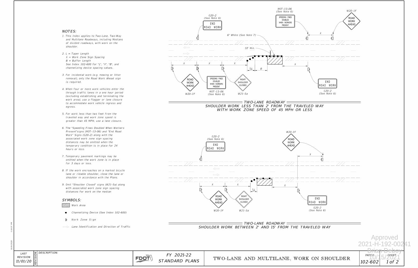
9. Omit "Shoulder Closed" signs (W21-5a) along
shoulder in accordance with the Plans.
lane or ridable shoulder, close the lane or
8. If the work encroaches on a marked bicycle
for 3 days or less.
omitted when the work zone is in place
7. Temporary pavement markings may be
hours or less.
temporary condition is in place for 24
distances may be omitted when the
associated work zone sign spacing
Work” Signs (G20-2) along with the
Present”signs (MOT-13-06) and “End Road
6. The “Speeding Fines Doubled When Workers
greater than 45 MPH, use a lane closure.
traveled way and work zone speed is
5. For work less than two feet from the
egress.
to accommodate work vehicle ingress and
work area), use a flagger or lane closure
(excluding establishing and terminating the
through traffic lanes in a one hour period
4. When four or more work vehicles enter the
is required.
removal), only the Road Work Ahead sign
3. For incidental work (e.g. mowing or litter
channelizing device spacing values.
See Index 102-600 for “L”, “X”, "B", and
B = Buffer Length
X = Work Zone Sign Spacing
2. L = Taper Length
shoulder.
of divided roadways, with work on the
and Multilane Roadways, including Medians
1. This Index applies to Two-Lane, Two-Way
10/9/2020
1:1
8:3
7 P
M
RE
VISIO
N DESCRIPTION:
REVISION
LAST
ofSTANDARD PLANS
FY 2021-22 SHEETINDEX
1 TWO-LANE AND MULTILANE, WORK ON SHOULDER
11/01/20 2102-602
NOTES:
W20-1F (See Note 6)
MOT-13-06(See Note 6)
G20-2
WITH WORK ZONE SPEED OF 45 MPH OR LESS
SHOULDER WORK LESS THAN 2' FROM THE TRAVELED WAY
TWO-LANE ROADWAY
(See Note 6)
G20-2
(See Note 6)
MOT-13-06
(See Note 6)
G20-2
SHOULDER WORK BETWEEN 2' AND 15' FROM THE TRAVELED WAY
TWO-LANE ROADWAY
(See Note 6)
G20-2
6" White (See Note 7)
B
W21-5a
CLOSED
SHOULDER
RIGHT
W20-1F
W21-5a
CLOSED
SHOULDER
RIGHT
W20-1F
W20-1F
XX X
ƿL
10' Min.
X
X
XX
ƿL
X
X
Approved2021-H-192-00241
Brian Deboy10/15/2021

SYMBOLS:
Work Zone Sign
Work Area
AHEAD
WORK
ROAD
PRESENT
WHEN WORKERS
DOUBLED
SPEEDING FINES
ROAD WORK
END
ROAD WORK
END
AHEAD
WORK
ROAD
Channelizing Device (See Index 102-600)
Lane Identification and Direction of Traffic
10/9/2020
1:1
8:4
8 P
M
RE
VISIO
N DESCRIPTION:
REVISION
LAST
ofSTANDARD PLANS
FY 2021-22 SHEETINDEXINDEX
TWO-LANE AND MULTILANE, WORK ON SHOULDER 102-60211/01/20 22
W20-1F (See Note 6)
MOT-13-06(See Note 6)
G20-2
WITH WORK ZONE SPEED OF 45 MPH OR LESS
SHOULDER WORK LESS THAN 2' FROM THE TRAVELED WAY
MULTILANE ROADWAY
(See Note 6)
G20-2
SHOULDER WORK BETWEEN 2' AND 15' FROM THE TRAVELED WAY
MULTILANE ROADWAY
6" White (See Note 7)
Median
Median
B
CLOSED
SHOULDER
RIGHT
(See Note 9)
W21-5a
CLOSED
SHOULDER
RIGHT
W20-1F
(See Note 9)
W21-5a
XX X
ƿL
10' Min.
X
XX
ƿL
X
Approved2021-H-192-00241
Brian Deboy10/15/2021

CROSS HERE
AHEADSIDEWALK CLOSED
DETOURDETOUR
DETOUR
CROSS HERE
AHEADSIDEWALK CLOSED
USE OTHER SIDE
SIDEWALK CLOSED
USE OTHER SIDE
SIDEWALK CLOSED CLOSED
SIDEWALK
DETOUR
AHEAD
WORK
ROAD
AHEAD
WORK
ROAD
DETOUR
DETOUR
SYMBOLS:
Work Zone Sign
Lane Identification and Direction of Traffic
M4-9BR
M4-9BL
M4-9BL
M4-9BR
W20-1F
W20-1F
R9-11AR
R9-11AL
Pedestrian Longitudinal Channelizing Device (LCD)
M4-9BL
M4-9BR
PEDESTRIAN DETOUR
Work Area
(See Note 4)
R9-10
(See Note 4)
R9-10
(See Note 4)
R9-9
NOTES:
facilities (e,g,, transit stops, residences, or business entrances).
Omit the Advance Closure LCD if it blocks access to other pedestrian 5.
in accordance with the manufacturer's instructions.
4. "Sidewalk Closed" signs (R9-XX) may be mounted on pedestrian LCDs
panel to the surface of the sidewalk.
maintain a minimum 7’ clearance from the bottom of the sign
3. For post mounted signs located near or adjacent to a sidewalk,
Place pedestrian LCDs across the full width of the closed sidewalk.2.
closed crosswalks.
Cover or deactivate pedestrian traffic signal display(s) controlling 1.
(See Notes 4 and 5)
Advance Closure LCD
(See Notes 4 and 5)
Advance Closure LCD
10/12/2020
6:2
4:0
2
AM
RE
VISIO
N DESCRIPTION:
REVISION
LAST
ofSTANDARD PLANS
FY 2021-22 SHEETINDEX
102-660 1 211/01/20SIDEWALK CLOSURE
Approved2021-H-192-00241
Brian Deboy10/15/2021

C C
W4-2
PRESENT
WHEN WORKERS
DOUBLED
SPEEDING FINES
AHEAD
WORK
ROAD
(See Note 4)
G20-2
ROAD WORK
END
AHEAD
CLOSED
LANE
RIGHT
W20-5(See Note 4)
MOT-13-06W20-1F
AHEAD
WORK
ROAD
W20-1F
NOTES:
SYMBOLS:
Channelizing Device (See Index 102-000)
Crash CushionC C
Existing Sidewalk
Existing Sidewalk
Temporary Barrier
6" White
Work Zone Sign
Lane Identification and Direction of Traffic
Pedestrian Longitudinal Channelizing Device (LCD)
Work Area
Arrow Board
Merge
Arrow Board Mode:
10/12/2020
6:2
4:0
7
AM
RE
VISIO
N DESCRIPTION:
REVISION
LAST
ofSTANDARD PLANS
FY 2021-22 SHEETINDEX
102-660 2 211/01/20SIDEWALK CLOSURE
TEMPORARY PEDESTRIAN WAY
(Temporary Barrier Shown, Low Profile Barrier Similar)
TEMPORARY PEDESTRIAN WAY DIVERTING TRAFFIC INTO THE TRAVELED WAY
100'
B XLXXXX
X
Temporary Pedestrian Way
hours or less.
distances, may be omitted when the work zone will be in place for 24
and "End Road Work" signs (G20-2), along with associated work zone sign
4. The "Speeding Fines Doubled When Workers Present" signs (MOT-13-06)
for curb ramps diverting pedestrian traffic into a closed lane.
requirements of Index 522-002. Detectable warnings are not required
3. When temporary pedestrian ways require curb ramps, meet the
5' in width at intervals not to exceed 200'.
Provide a 5' x 5' passing space for temporary pedestrian ways less than
of 0.02, except where space restrictions warrant a minimum width of 4'".
2. Provide a 5' wide temporary pedestrian way with a maximum cross-slope
See Index 102-600 for "L", "B", "X", channelizing device spacing values.
X=Work Zone Sign Distance
B=Buffer Length
1. L=Taper Length
Approved2021-H-192-00241
Brian Deboy10/15/2021