Embed Size (px)
Citation preview

ENGINEER’S MANUAL
40019500No.E359-00
SC-500
R

PREFACE
This Engineer’s Manual is written for the technical personnel who are responsible for the service and maintenance
of the machine.
The Instruction Manual for these machines intended for the maintenance personnel and operators at an apparel
factory contains operating instructions in detail. And this manual describes “Standard Adjustment”, Adjustment
Procedures”, “Results of Improper Adjustment”, and other important information which are not covered in the
Instruction Manual.
It is advisable to use the relevant Instruction Manual and Parts List together with this Engineer’s Manual when
carrying out the maintenance of these machines.
This manual gives the “Standard Adjustment” on the former page under which the most basic adjustment value
is described and on the latter page the “Results of Improper Adjustment” under which stitching errors and
troubles arising from mechanical failures and “How To Adjust” are described.

SAFETY DEVICE
Safety devices described below vary in accordance with the destination and specifications.
Power connector cover
Cover to prevent connectorsfrom electric shock due tohigh voltage section.
Power voltage danger label
Cautions for usable powervoltage are described.
Roll-in prevention pin
Pin to prevent roll-in by V belt.
Electric shock danger label
This label indicates thatthere is a danger of electricshock in the cover on whichthe label is pasted.
Electric shock danger label
This label indicates that thereis a danger of electric shockin the cover on which thelabel is pasted.
Motor fan cover
Cover to prevent motorfan from coming in contactwith other components.
-i-
Motor pulley cover
Cover to prevent motor pulleyand V belt from coming incontact with each other.

CONTENTS1. SPECIFICATIONS ...................................................................................... 12. OUTLINE .................................................................................................... 1
(1) Features ................................................................................................................... 1
3. MODEL CONSTRUCTION ......................................................................... 1(1) SC-500 ..................................................................................................................... 1(2) M-50 ......................................................................................................................... 1
4. CONFIGURATION ...................................................................................... 2(1) DDL-8700/SC-500/M-50 ........................................................................................... 2
5. EXPLANATION OF OPTIONAL CONTROL PANEL .................................3(1) List of control panel of CP-160 ................................................................................. 3(2) Explanation of control panel CP-160 ........................................................................ 4(3) Example of application ............................................................................................. 5
6. CONTROL BOX (SC-500) ..........................................................................7(1) Arrangement of connectors ...................................................................................... 7(2) How to use the standard operation panel ................................................................. 8(3) Setting for functions of SC-500 ............................................................................... 13(4) Function setting list ................................................................................................. 15(5) Detailed explanation of selection of functions ........................................................ 19(6) Automatic compensation of neutral point of the pedal sensor ................................ 30(7) Initialization of the setting data ............................................................................... 30
7. CHANGING PROCEDURE OF THE PEDAL TYPE ................................. 318. CONNECTING PROCEDURE WITH JUKI OPTIONAL DEVICES .......... 32
(1) Bobbin thread remaining amount detection device, AE ......................................... 32(2) Connection of the pedal of standing-work machine ................................................ 32(3) Setting of the auto lifter function ............................................................................. 33(4) Connection of the material end sensor (ED) .......................................................... 33(5) Connecting procedure of CP-160 ........................................................................... 34
9. EXTERNAL INPUT/OUTPUT CONNECTOR (SIGNAL CONNECTOR FOR EXTENSION) ............................................3410. CONNECTOR CONNECTION DIAGRAM.............................................. 35
(1) Solenoid for machine head .................................................................................... 35(2) Solenoid for lifting presser foot ............................................................................... 35(3) Optional cord .......................................................................................................... 36
11. MAINTENANCE...................................................................................... 37(1) Replacing the fuse ................................................................................................. 37(2) Changing procedure between 100V to 120V and 200V to 240V ............................ 39(3) Control voltage check terminal of CTL circuit board ............................................... 40
12. ERROR CODES .....................................................................................41(1) Error code list ......................................................................................................... 42
13. BLOCK DIAGRAM .................................................................................4314. DRAWING OF THE TABLE (FOR DDL-8700) ....................................... 44

- 1 -
(1) SC-500Electric equipment corresponding to new servo motor (for export)
1. SPECIFICATIONS
(1) Features1) Voltage changeover function of single phase 100 to 120V/3-phase 200 to 240V is provided. (Adapting to
a part of specifications only) The control box with voltage changeover function can be used either for single phase 100 to 120V or for
3-phase 200 to 240V by replacing the power cord up to the power switch and setting the voltagechangeover connector inside the control box.
2) The operation panel is assembled in the control box as standard and it is possible to operate the machinewith the single unit of the control box.
By connecting the optional operation panel, CP-160, function and operability are further improved.3) The conventional JUKI optional devices can be used without any adjustment. However, it is necessary to separately purchase the optional circuit board.
Supply voltage Single phase 100 to 120V 3-phase 200 to 240V Single phase 200 to 240V
Frequency 50 Hz / 60 Hz 50 Hz / 60 Hz 50 Hz / 60 Hz
Operating temperature range Temperature : 0 to 40˚C Temperature : 0 to 40˚C Temperature : 0 to 40˚C
Operating humidity range Humidity : 90% or less Humidity : 90% or less Humidity : 90% or less
Power consumption 390VA 390VA 390VA(460VA when LZ-228* is used) (460VA when LZ-228* is used) (460VA when LZ-228* is used)
6 Control box classification
S JUS (LA) : Single phase 100 to 120V PFL
D JUS : 3-phase 200 to 240V PFL
K General export : Single phase 200 to 240V PFL
N CE : Single phase 200 to 240V PFL
U China : Single phase 200 to 240V PFL
7 Electric equipment type classification
S Standard
9 Destination spec. classification
A Standard
10 Accessory spec. classification
A Standard
11 Delivery voltage classification
4 200 to 240V
4 Voltage classification
D 3-phase 0 to 340V DC
5 to 7 Pulley and belt classification
Code Pulley and belt Applicable model
Q41 ø110 : M41 inch DDL-8700-7
* Pulley diameter: outer diameter is indicated.
3. MODEL CONSTRUCTION
9 Destination spec. classification
A Standard, Hong Kong, Singapore
B Europe
D America (including LA)
G China
10 Accessory spec.
classification
A Standard
11 Delivery voltage
classification
4 200 to 240V
(Caution) 1. Power consumption is the mean power consumption when SC-500 is mounted on DDL-8700in accordance with the operating conditions JUKI settles.
2. Power consumption varies in accordance with the operating conditions and the machinehead on which SC-500 is mounted. So, be careful.
3. There are cases where the momentary maximum power consumption is 1.5 times or morethan the mean power consumption.
2. OUTLINE
(2) M-50Servo motor for SC-500 (for export)
1 2 3 4 5 6 7 8 9 10 11
S C 5 0 0 - A A 4
1 2 3 4 5 6 7 8 9 10 11
M 5 0 D - A 4

- 2 -
4. CONFIGURATION(1) DDL-8700/SC-500/M-50
1
2
5
4
3
6
7
8
!1
!2
1 Power switch
2 Control panel
3 Synchronizer
4 L-shaped thread stand
5 PSC box (SC-500)
6 Max. speed control knob
7 Motor (M-50)
8 Operation pedal
9 Touch-back switch
!0 Thread wiping (wiper) device
!1 Screw or caster for level adjustment of table / stand
!2 Resistor pack
!0
9

- 3 -
5
4
3
5
7
8
9
!0 !1
!2 !3
!4 !5 !7 !8
!6
!9
5. EXPLANATION OF OPTIONAL CONTROL PANEL
1) For the connecting destination of the connector, refer to the item (5) of 8. CONNECTING PROCEDURE WITH JUKI OPTIONAL DEVICES.2) By connecting of CP-160, all displays of standard operation panel of SC-500 go off. However, error code No. is displayed only at the time of occurrence of error.
Description
Power indication LED : Lights up when the power switch is turned ON.
Max. speed limit variable resister : Maximum speed is limited when this resister is moved in the left direction ( ).
Reverse stitching pattern switch : Used for specifying the reverse stitching pattern to be sewn.
Overlapped stitching pattern switch : Used for specifying the overlapped stitching pattern to be sewn.
Constand dimension stitching pattern switch : Used for specifying the constant dimension stitching pattern to be sewn.
Rectangular stitching pattern switch : Used for specifying the rectangular stitching pattern to be sewn.
Automatic reverse stitching at the start of sewing switch : Used for turning ON / OFF the automatic reverse stitchingat the start of sewing.
Automatic reverse stitching at the end of sewing switch : Used for turning ON / OFF the automatic reverse stitching atthe end of sewing.
Automatic double reverse stitching at the start of sewing switch : Used for turning ON / OFF the automatic doublereverse stitching at the start of sewing.
Automatic double reverse stitching at the end of sewing switch : Used for turning ON / OFF the automatic doublereverse stitching at the end of sewing.
Switches for setting the number of stitches : Used for setting the number of stitches to be sewn in processes A through D.
Material edge sensor ON / OFF switch : Rendered effective when the material edge sensor is installed on the machine.Used for selecting whether or not the material sensor is used during sewing.
One-shot automatic stitching switch : Start the sewing machine with this switch, and the sewing machine will runautomatically until the material edge is detected or the end of the set number of stitches is reached.
Automatic thread trimming switch : When the material edge is detected, the machine will perform thread trimming evenwhen keeping depressing the front part of the pedal.
Thread trimming prohibition switch : Used for prohibiting thread trimming at any occasion.
Bobbin thread counter : Indicates the amount of bobbin thread while counting it by subtracting from the set value. Whenthe bobbin thread remaining amount detecting device is installed on the machine, the counter indicates the number oftimes of detecting.
Bobbin counter reset switch : Used for returning the value shown on the bobbin thread counter to the initial value.
Bobbin thread amount setting switch : Used for setting the amount of bobbin thread.
Needle up/down compensating switch : Used when performing needle up / down compensating stitching.
No
(1) List of control panel of CP-1601
2
1
2
3
4
5
6
7
8
9
!1
!2
!3
!4
!5
!6
!7
!8
!9
!0

- 4 -
(2) Explanation of control panel CP-160
1) Reverse stitching patternWhen the sewing machine performs the free stitching operation, the
machine performs the reverse stitching operation at the start and end of
sewing.
The reverse stitching operation can set the ON and OFF settings.
Furthermore, single and double reverse stitching patterns can be
selected.
Setting of number of stitches or other settings can be performed by
operating the control panel.
A, B, C and D = 0 to 19 stitches
2) Overlapped stitching patternThe sewing machine repeats the normal stitching and reverse stitching
by the predetermined time, and performs the line bartacking. Then, the
machine makes the thread trimmer actuate and stop to complete the
overlapped stitching procedure.
Change of the number of stitches or the number of times of repetition
can be performed by operating the control panel.
A, B and C = 0 to 19 stitches
D = 0 to 9 times
3) Constant-dimension stitching patternThe free stitching process in the reverse stitching pattern becomes the
set value of the number of stitches. The sewing machine will automatically
stop (automatically perform thread trimming if the automatic thread
trimming is selected.) after the machine finishes the predetermined
number of stitches in the process of CD.
If the automatic thread trimming is not selected, operate the touch-back
switch after the machine has automatically stopped. Then, the machine
runs at a low speed (stitch compensation operation). Also, if the pedal is
returned to its neutral position and depressed its front part again, the
sewing can be continued regardless of the setting of number of stitches.
Setting of number of stitches or selection of automatic thread trimming
can be performed by operating the control panel.
A and B = 0 to 19 stitches CD = 0 to 500 stitches
4) Rectangular stitching patternThere are 4 operation steps in the process of constant-dimension stitching
pattern. At each operation step the sewing machine automatically stops
after sewing the predetermined number of stitches. At this time, if the
touch-back switch is operated, the sewing machine runs at a low speed
(stitch compensation operation). Also, in case of the last operation step,
if the pedal is returned to its neutral position and depressed its front part
again, the sewing can be continued regardless of the setting of number
of stitches. However, if the automatic thread trimming is set, the machine
will perform thread trimming. Setting of number of stitches or selection
of automatic thread trimming can be performed by operating the control
panel.
A and B = 0 to 19 stitches C and D = 0 to 99 stitches

- 5 -
(3) Example of application
1) When the CP-160 is used together with the material end sensor (ED : optional), it
can be used as a small edge-controller.
(Method) Adjust the position to mark 3 of the CP-160, turn ON material end sensor ON/OFF switch !2
of the CP-160, and turn ON mark !3 of the automatic one-shot stitching.
3 !2 !3
Caution) Number of rotations of the automatic one-shot stitchig can be changed by the functionsetting (No. 38).
2) Label attaching is performed by the automatic one-shot stitching with the CP-160(Method) Select mark 5 on the CP-160, and turn ON mark !3 of the automatic one-shot stitching.
5 !3
Explanation) Number of stitches at the section CD can be set up to 500 stitches. If the stitch length is 2 mm,it is possible to sew approximately 1,000 mm (1 m).This function can perform the automatic one-shot stitching without using the material endsensor (ED : optional). Therefore, the sewing machine performs the sewing to the last accordingto the sewing pattern even if the label is not located at the end of material when the pedal isdepressed once.
Label
CD
CD

- 6 -
3) Seam joining of the reverse feed stitching at the end of sewing (For thick materials)Especially some sewing machine heads for thick materials are likely to fail joining the seam at the section of
the following figure even if the timing of reverse feed stitching at the end of sewing is compensated.
1 At the timing to move to the reverse feed
stitching action, the rotating speed at the section
where the sewing machine is rotated at a low
speed can be changed.
SC-500 function setting No. 64
(0 to 250 rpm changeable)
Example) Use for reference.
Speed
Section of EBT
Section of lowspeed
Time
1
Machine head of DDL-8700H (for thick materials)
Stitch length 4 mm
Number of stitches 4 stitches
ITEM No. 64 170 rpm
Machine head of DDL-8700H (for thick materials)
Stitch length 4 mm
Number of stitches 4 stitches
ITEM No. 64 “0” rpm
Condition Condition
Stitch lenthbecomes small.
Stitchlengthslips off.
Standard

- 7 -
Following connectors are prepared when loosening the front cover fixing screws A of SC-500 and opening the
cover. Connect the machine head connectors to the positions corresponding to each other so as to fit the
devices mounted on the machine head.
WARNING :• To prevent personal injury caused by abrupt start of the sewing machine, carry out the work after
turning OFF the power switch and a lapse of 5 minutes or more.• To prevent damage of device caused by maloperation and wrong specifications, be sure to connect
all the corresponding connectors to the specified places.• To prevent personal injury caused by maloperation, be sure to lock the connector with lock.• As for the details of handling respective devices, read carefully the Instruction Manuals supplied
with the devices before handling the devices.
(1) Arrangement of connectors
A
9
2 31
4 5
!0
7
!2
OPC circuit board A (asm.)
!3
AFront cover
6 8
!1
!4
!5
!6
1 CN30 Motor signal connector
2 CN32 Machine head connector
3 CN33 Needle bar position detector connector
4 CN36 Machine head solenoid connector
5 CN37 Presser foot lifter solenoid connector
6 CN38 CP-160 panel connector
7 CN39 Standing machine pedal connector
8 CN40 Signal for extension connector
9 CN51 Not used
!0 CN52 Not used
!1 CN53 Bobbin thread remaining amount detection solenoid connector
!2 CN189 External interface signal connector
!3 CN59 Bobbin thread count-up output connector
!4 CN55 Material end detection sensor (ED) connector
!5 CN58 Standing machine pedal connector
!6 CN57 Bobbin thread remaining amount detection sensor connector
6. CONTROL BOX (SC-500)

- 8 -
1 / switch : Used for determining the contents of setting.When this switch is pressed, flashing stops and the contents of settingare determined.
2 / switch : Used for changing the contents of setting.When this switch is pressed, changeable positions flash on and off.By pressing the switch, flashing position shifts in the right direction.
3 switch : Used for changing the contents of the selected display (flashingsection).When this switch is pressed, the contents of the displayincrease.
4 switch : Used for changing the contents of the selected display (flashingsection).When this switch is pressed, the contents of the display decrease.
5 PATTERN SELECTION display : The selected pattern is displayed.
6 REVERSE STITCHING : Rendered effective when reverse stitching pattern is selected.AT START display “ ” Without reverse stitching display / “ ” Reverse stitching display/
“ ” Double reverse stitching display
7 REVERSE STITCHING : Rendered effective when reverse stitching pattern is selected.
AT END display “ ” Without reverse stitching display / “ ” Reverse stitching display/
“ ” Double reverse stitching display
8 NUMBER OF STITCHES display : Number of stitches of reverse stitching or overlapped stitching isdisplayed.
9 MATERIAL EDGE SENSOR : Lights up when the material edge sensor setting is selected.display Function setting No. 2
!0 ONE-SHOT AUTOMATIC : Lights up when the one-shot automatic stitching is selected.STITCHING display Function setting No. 76
!1 AUTOMATIC : Lights up when the automatic thread trimming by depressing theTHREAD TRIMMING display front part of the pedal is selected.
Function setting No. 3!2 THREAD TRIMMING : Lights up when the thread trimming prohibition is selected.
PROHIBITION display Function setting No. 9
1 2 4 3 !1 !2
6 7 8 9 !05
(2) How to use the standard operation panel

- 9 -
(3) Press switch 3 or switch 4 and
select the reverse stitching pattern.
Reverse stitching patterns and displays are as
follows.
: Reverse stitching
: Double reverse stitching
: Without reverse stitching
(4) Press / switch 1 to make reverse
stitching at end display 7 flash on and off, and set
the pattern in the same way as step 3).
[ Setting procedure of the reverse stitching ]
(1) Hold pressing / switch 1, and press
/ switch 2 to select the reverse
stitching pattern.
(Every time / switch 2 is pressed,
reverse stitching pattern/overlapped stitching
pattern change over alternately.)
(2) Press / switch 1 to make reverse
stitching at start display 6 flash on and off.
Every time / switch 1 is pressed, the
flashing position shifts in the right direction.
(Caution) The sewing machine does not start
in the flashing state.
Operating procedure of the sewing pattern
1. Reverse stitching pattern
Reverse stitching patterns below can be set by using the operation panel.
Reverse stitching patterns that can be set
Reverse stitching
at start display
Sewing pattern
A
Overlapped stitching patternReverse stitching pattern
B
D
CD
C
A
B
A
B B
A
D
C
D
C
A
B
A
B
A
B
D
C
D
C
D
C
D
C
D
C
A
B
A
B
12 12
1
Shift directionFlash
Contents of reversestitching slection
updating with swith 3
34
76
76Flash
updating with swith 4
1
Reverse stitchingat end display

- 10 -
2. Overlapped stitching pattern
Overlapped stitching patterns below can be set by using the operation panel.
A : Number of stitches of normal stitching setting0 to 15 stitches
B : Number of stitches of reverse stitching setting0 to 15 stitches
C :Number of stitches of normal stitching setting0 to 15 stitches
D : Number of times of repetition
0 to 9 times
(Caution) When process D is set to 5 times, thesewing is repeated as A / B / C / B / C.
[Setting procedure of the overlapped stitching](1) Hold pressing / switch1, and press
/ switch 2 to select the overlapped stitching
pattern.
(Every time / switch 2 is pressed,
reverse stitching pattern/overlapped stitching
pattern change over alternately.)
(2) The number of stitches for process A becomes in
flashing state.
(3) Every time / switch 1 is pressed, the
flashing position shifts in the right direction and the
display of the process where setting can be
changed flashes on and off.
(4) Press switch 3 or switch 4 to
change the number of stitches.
(5) When the setting of all processes has been
completed, press / switch 2 to
determine the contents of the setting. (Flashing
stops.)
(Caution) When the overlapped stitching isselected, the automatic operation displayflashes on and off. It is not possible torelease the automatic operation.
(5) Press / switch 1 to make number of
stitches display 6 flash on and off, and set the
number of stitches for the respective processes of
the stitching.
(6) Press switch 3 or switch 4 to
change the number of stitches.
The number of stitches can be changed up to as
many as 15 stitches for the A, B, C, and D
processes respectively.
However, displays are as follows.
10 stitches = A, 11 stitches = b, 12 stitches = c, 13
stitches = d, 14 stitches =E and 15 stitches = F
(7) When the setting of all items has been completed,
press / switch 2 to determine the
contents of the setting. (Flashing stops.)
12 4 3
8
A
B
C
B
C
D
12 12
12 4 3
6
Overlapped stitching patternReverse stitching pattern

- 11 -
1 34
a
a
1 3
1 34
1 34
3. Special settingFor material end sensor function, automatic thread trimming function, one-shot automatic stitching function and threadtrimming prohibition function which are displayed in the front panel, it is possible to change the set value by directlymoving to the function setting mode while the power is turned ON in addition to the normal function setting procedure.
[ Moving procedure to the function setting mode ]
(1) Hold pressing / switch 1, and press
switch 3 to move to the function setting
mode.
(Caution) Function setting No. 2 is displayedimmediately after the changeover.
(2) When returning to the normal mode, press /
switch 2 and determine the contents of
the setting.
1) Material end sensor function setting (Function
setting No. 2)
It is rendered effective when connecting the
optional material end sensor.
It is possible to change the set value with
switch 3 or switch 4
0 : Material end sensor function is prohibited.
1 : Material end sensor function is effective.
When "1" is selected, material
end sensor display lights up
when the mode has returned to
the normal one.
2) Thread trimming operation after material end stop
setting (Function setting No. 3)
Press / switch 1 to advance to the
function setting No. 3.
It is possible to change the set value with
switch 3 or switch 4.
0 : Material end stop
1 : Automatic thread trimming after detection
of material end
When "1" is selected, the
automatic thread tr imming
display lights up when the mode
is returned to the normal one.
3) Number of stitches to stop the sewing machine after
detection of material end setting (Function setting
No. 4)
Press / switch 1 to advance to the
function setting No. 4.
It is possible to change the set value with
switch 3 or switch 4.
Specified number of stitches : 0 to 19 stitches
2

- 12 -
a
a
1 34
1 34
4) One-shot automatic stitching setting function
(Function setting No. 76)
Press / switch 1 to advance to the
function setting No. 76.
It is possible to change the set value with
switch 3 or switch 4.
0 : Pedal designated speed is prior.
1 : Automatic operation
(Caution) 1. It is rendered effective when the material end sensor function is set.
It is not possible to prohibit the one-shot operation at the time of the verlapped stitching operation.
2. Speed of rotation is the speed set at the function setting No. 38.
When "1" is selected, the one-
shot automatic stitching display
lights up when the mode is
returned to the normal one.
5) Thread trimming prohibition function setting
(Function setting No. 9)
Thread trimming operation at normal stitching and
overlapped stitching can be prohibited by selecting
the thread trimming prohibition.
Press / switch 1 to advance to the
function setting No. 9.
It is possible to change the set value with
switch 3 or switch 4.
0 : Thread trimming is effective.
1 : Thread trimming is prohibited.
When "1" is selected, the thread
trimming prohibition display lights
up when the mode is returned to
the normal one.
(Caution) When the specified number of stitches
is insufficient, there is a case where the
sewing machine cannot stop within the
specified number of stitches depending on
the speed of rotation of the sewing
machine.

- 13 -
Functions can be selected and specified by means of the four setting switches and light emitting diode
located inside the front cover of the SC-500.
(Caution) 1. Do not perform switch operations other than those described in the following explanations.2. Be sure to re-turn the power switch ON after one second or more has passed. If the power
is turned ON immediately after turning it OFF, the sewing machine may not work normally.In this case, turn ON the power again.
How to change over to the function setting modo
(1) Turn OFF the power to the unit.
(2) Pressing switch 4, turn ON the power to the unit.
(3) Indication 5, 6 will be shown on the display. (If
the indication fails to change, re-perform the
procedures 1) and 2).
1 2 3 4
56
4
4
1 Switch for entering specified value changedand updating setting No. in DOWN direction
2 Switch for entering specified value changedand updating setting No. in UP direction
Specified valueSpecified No.
3 Down switch (DOWN)4 Up switch (UP)
(3) Setting for functions of SC-500
- 14 -
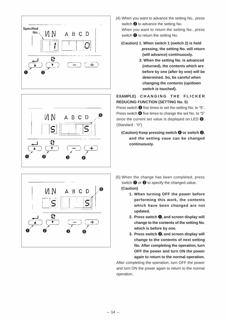
(4) When you want to advance the setting No., press
switch 2 to advance the setting No.
When you want to return the setting No., press
switch 1 to return the setting No.
(Caution) 1. When switch 1 (switch 2) is held
pressing, the setting No. will return
(will advance) continuously.
2. When the setting No. is advanced
(returned), the contents which are
before by one (after by one) will be
determined. So, be careful when
changing the contents (up/down
switch is touched).
EXAMPLE) C H A N G I N G T H E F L I C K E R
REDUCING FUNCTION (SETTING No. 5)
Press switch 2 five times to set the setting No. to “5”.
Press switch 4 five times to change the set No. to “5”
since the current set value is displayed on LED 5.
(Standard : “0”)
(Caution) Keep pressing switch 4 or switch 3,
and the setting vaue can be changed
continuously.
(5) When the change has been completed, press
switch 1 or 2 to specify the changed value.
(Caution)
1. When turning OFF the power before
performing this work, the contents
which have been changed are not
updated.
2. Press switch 1, and screen display will
change to the contents of the setting No.
which is before by one.
3. Press switch 2, and screen display will
change to the contents of next setting
No. After completing the operation, turn
OFF the power and turn ON the power
again to return to the normal operation.
After completing the operation, turn OFF the power
and turn ON the power again to return to the normal
operation.
21
21 43
5
21 43
5
SpecifiedNo.

- 15 -
* Functions with * (asterisk) are those for maintenance. Be very careful of changing the set value.
Indication offunction settingItem
Soft startfunction
Material endsensor function
Thread trimmingfunction bymaterial endsensor
Number ofstitches formaterial endsensor
Flickerreducingfunction
Bobbin threadcountingfunction
Unit of bobbinthreadcounting down
Number ofrotation ofreverse feedstitching
Threadtrimmingprohibitingfunction
Setting ofneedle barstop positionwhen thesewingmachine stops.
Click sound ofkey switchmounted onPSC
Optinal switchfunctionselection
Function ofprohibiting startof the sewingmachine bybobbin threadcounter
Sewingcounter
Number of timesof detection ofrun-out of bobbinthread remainingamount
Function ofneutral presserlifting
No.
1
2
3
4
5
6
7
8
9
10
11
12
13
14
15
21
Settingrange
0 to 9(Stitches)
0/1
0/1
0 to 19(Stitches)
0 to 8
0/1
0 to 2
150 to 3,000(r.p.m.)
0/1
0/1
0/1
0 to 8
0 to 2
0/1
0 to 19
0/1
Description
The number of stitches to be sewn at a low speed when the soft-startfunction is used at the start of sewing.
0 : Soft-start function is not operative.
Material end sensor function (used in case of without panel).0 : Material end detection function is not operative.1 : After detecting material end, the specified number of stitches (No.
4) will be sewn, and the sewing machine will stop.
Thread trimming function by material end sensor (used in case of withoutpanel).
0 : Automatic thread trimming function after detection of material endis not operative.
1 : After detecting material end, the specified number of stitches (No.4) will be sewn, and the sewing machine will stop and performautomatic thread trimming.
Number of stitches for material end sensor (used in case of without panel).Number of stitches from detection of material end to stop of the sewingmachine.
Flicker reducing function (If the hand lamp flickers).0 : Flicker reducing function is not operative.1 : Less effective 8 : Highly effective
Bobbin thread counting function0 : Bobbin thread counting function is not operative.1 : Bobbin thread counting function is operative.
Unit of bobbin thread counting down0 : Count/10 stitches1 : Count/15 stitches2 : Count/20 stitches
Sewing speed of reverse feed stitching
Thread trimming prohibiting function (used in case of without panel).0 : Thread trimming prohibiting function is not operative.1 : Thread trimming is prohibited.
(Output of solenoid is prohibited. : Thread trimmer and wiper)
Position of needle bar is specified when the sewing machine stops.0 : Predetermined lowest position1 : Predetermined highest position
Click sound of key switch mounted on PSC is specified.0 : Click is not operative.1 : Click is operative.
Switching of function of optional switch.0 : No function1 : Needle up/down compensating stitching2 : Back compensating stitching3 : Function of canceling once reverse feed stitching at the end of sewing4 : Thread trimming function5 : Presser foot lifting function6 : One stitch compensating stitching7 : Function of simultaneously canceling reverse feed stitching at the
start and end of sewing8 : Presser foot lifting function when pedal is neutral
Function of prohibiting start of the sewing machine by bobbin thread counting0 : When counting is out (-1 or less) Function of prohibiting start of the
sewing machine is not operative.1 : When counting is out (-1 or less) Function of prohibiting start of the
sewing machine after thread trimming is operative.2 : When counting is out (-1 or less), the sewing machine stops once.
Function of prohibiting start of the sewing machine after threadtrimming is operative.
Counting function of sewing (number of completion of process)0 : Sewing counter function is not operative.1 : Sewing counter function is operative.
Number of times of detection of run-out of bobbin thread remaining amount0 : Function of bobbin thread remaining amount is not operative.
1 to 19 : Number of times during which the signal is not made even ifrun-out of bobbin thread remaining amount is detected.
Function of lifting presser foot when the pedal is in neutral position.0 : Function of neutral automatic presser lifting is not operative.1 : Selection of function of neutral presser lifting.
Ref.page
19
19
19
19
19
19
19
19
20
20
26
20
20
3 0
4 5
5 0
8 1 9 0 0
1 1 1
1 2 0
1 4 1
1 0
2 0
6 1
7 0
9 0
1 0 0
1 3 0
1 5 1
2 1 0
(4) Function setting list
*

- 16 -
38
39
40
41
42
43
One-shotspeed
Pedal stroke atthe start ofrotation
Low speedsection ofpedal
Startingposition oflifting presserfoot by pedal
Startingposition ofloweringpresser foot
Pedal stroke 2for startingthread trimming
One-shot speed (The max. value depends on the number of rotation ofthe sewing machine head.)
Position where the sewing machine starts rotating from pedal neutralposition (Pedal stroke)
Position where the sewing machine starts accelerating from pedal neutralposition (Pedal stroke)
Position where the cloth presser starts lifting from pedal neutral position(Pedal stroke)
Starting position of lowering presser footStroke from the neutral position
Position 2 where the thread trimming starts from pedal neutral position(When the function of lifting presser foot by pedal is provided.) (Pedalstroke)
150 to MAX(r.p.m.)
10 to 50(0.1 mm)
10 to 100(0.1 mm)
–60 to –10(0.1mm)
8 to 50(0.1 mm)
–60 to –10(0.1 mm)
*
Item
Function ofchangeover ofcompensatingswitch on theoperation panelfunction
Function of fineadjustment ofnumber ofrotation
Threadtrimmingmotioncondition
Function ofsetting theholding forceafter stop
Function ofsetting thereaction forceat the time ofretry
Suction time ofthe first start ofthe backsolenoid
Function ofreverse feedstitching on theway
Number ofstitches ofreverse feedstitching on theway
Effectivecondition ofreverse feedstitching on theway when thesewingmachine isstopping.
Threadtrimmingfunction byreverse feedstitching on theway
Number ofrotation at alow speed
Number ofrotation of soft-start
No.
22
24
25
26
27
29
30
31
32
33
35
37
Settingrange
0/1
–1.5% to1.5%
(0.1 %)
0/1
0 to 9
0 to 15
50 to 300(ms)
0/1
0 to 19(Stitches)
0/1
0/1
150 to 250(r.p.m.)
150 to MAX(r.p.m.)
Description
Function of needle up/down compensating switch on the operation panelcan be changed.
0 : Needle up/down compensation1 : One stitch compensation
Number of rotation can be compensated.Be sure to normally use this function with "0".
This function sets the thread trimming motion after DOWN position hasbeen off by turning handwheel by hand.
0 : Thread trimming after turning handwheel by hand is permitted.1 : Thread trimming after turning handwheel by hand is prohibited.
This function prevents the sewing machine from the reverse rotation after ithas stopped.
0 : Initial value1 : Less effective / 9 : Highly effective
This function sets the magnitude of return force of the needle bar beforethe retry motion.
1 : Less return force / 15 : High return force
This function sets the suction motion time of the back-tack solenoid.50 ms to 300 ms
Function of reverse feed stitching on the way0 : Function of reverse stitching on the way is not operative.1 : Function of reverse feed stitching on the way is operative.
Number of stitches of reverse feed stitching on the way.
Effective condition of reverse feed stitching on the way0 : Function is not operative when the sewing machine stops.1 : Function is operative when the sewing machine stops.
Thread trimming function by reverse feed stitching on the way0 : Automatic thread trimming function after completion of reverse feed
stitching on the way is not operative.1 : Automatic thread trimming after completion of reverse feed stitching
on the way is performed.
Lowest speed by pedal
Sewing speed at the start of sewing (soft-start)(The max. value dependson the number of rotation of the sewing machine head.)
Ref.page
21
29
21
21
21
21
22
22
22
22
28
19
23
27
27
27
27
27
*
Indication offunction setting
2 4 0
2 5 1
2 6 0
2 2 0
2 7 3
2 9 2 5 0
3 0 0
3 1 4
3 2 0
3 3 0
3 5 2 0 0
3 7 8 0 0
3 8 2 5 0 0
3 9 3 0
4 0 6 0
4 1 – 2 1
4 2 1 0
4 3 – 5 1
*
*
*
*
*
*
* Functions with * (asterisk) are those for maintenance. Be very careful of changing the set value.

- 17 -
* Functions with * (asterisk) are those for maintenance. Be very careful of changing the set value.
*
*
28
28
23
28
25
23
23
23
24
24
24
24
24
25
24
*
*
No. Item Description Settingrange
Ref.page
44
45
46
47
48
49
51
52
53
55
56
Pedal stroke forreaching themaximumnumber ofrotation
Compensation ofneutral point ofthe pedal
Auto-lifterselecting function
Holding time oflifting auto-lifter
Pedal stroke 1for startingthread trimming
Lowering time ofpresser foot
Compensation ofsolenoid-ontiming of reversefeed stitching atthe start ofsewing
Compensation ofsolenoid-offtiming of reversefeed stitching atthe start ofsewing
Compensation ofsolenoid-offtiming of reversefeed stitching atthe end ofsewing
Foot lift afterthread trimming
Reverserevolution to liftthe needle afterthread trimming
Position where the sewing machin reaches its highest sewing speed frompedal neutral position (Pedal stroke)
Compensation value of the pedal sensor
Auto-lifter selection0 : Solenoid drive system1 : Pneumatic drive system
Limitation time of waiting for lifting solenoid type auto-lifter device
Position where thread trimming starts from pedal neutral position (Standardpedal) (Pedal stroke)
Lowering time of presser foot after the pedal has been depressed.(Start of rotation of the sewing machine is delayed during this time.)
Compensation of starting the solenoid for reverse feed stitching whenreverse feed stitching at the start of sewing is performed.
Compensation of releasing the solenoid for reverse feed stitching whenreverse feed stitching at the start of sewing is performed.
Compensation of releasing the solenoid for reverse feed stitching whenreverse feed stitching at the end of sewing is performed.
Function of lifting presser foot at the time of (after) thread trimming0 : Not provided with the function of lifting presser foot after thread
trimming1 : Provided with the function of lifting presser foot automatically after
thread trimming
Function of reverse revolution to lift the needle at the time of (after) threadtrimming
0 : Not provided with the function of reverse revolution to lift the needleafter thread trimming
1 : Provided with the function of reverse revolution to lift the needleafter thread trimming
10 to 150(0.1 mm)
–15 to 15
0/1
10 to 600(second)
–60 to –10(0.1 mm)
0 to 250(10 ms)
–36 to 36(10˚)
–36 to 36(10˚)
–36 to 36(10˚)
0/1
0/1
57
58
59
60
61
Bobbin threadremainingamount detectionfunction
Function ofholdingpredeterminedupper/lowerposition of theneedle bar
Function of Auto/Manual change-over of reversefeed stitching atthe start ofsewing
Function of stopimmediately afterreverse feedstitching at thestart of sewing
Function ofstartingprohibition of thesewing machineby detection ofbobbin threadremainingamount
Function of detecting bobbin thread remaining amount at the time of(after) thread trimming
0 : Not provided with the function of detecting bobbin threadremaining amount
1 : Provided with the function of detecting bobbin thread remainingamount
Function of holding predetermined upper/lower position of the needlebar
0 : Not provided with the function of holding predetermined upper/lower position of the needle bar
1 : Provided with the function of holding predetermined upper/lowerposition of the needle bar
This function can specify the sewing speed of reverse feed stitching atthe start of sewing.
0 : The speed will depend on the manual operation by pedal, etc.1 : The speed will depend on the specified reverse feed stitching
speed (No. 8).
Function at the time of completion of reverse feed stitching at the startof sewing
0 : Not provided with the function of temporary stop of the sewingmachine at the time of completion of reverse feed stitching at thestart of sewing
1 : Provided with the function of temporary stop of the sewingmachine at the time of completion of reverse feed stitching at thestart of sewing.
Function of starting prohibition of the sewing machine by detection ofbobbin thread remaining amount
0 : This function does not stop the sewing machine when countingis out (-1 or less).
1 : This function stops the sewing machine when counting is out (-1or less).
0/1
0/1
0/1
0/1
0/1
4 4 1 5 0
4 5 0
4 6 0
4 7 6 0
4 8 3 5
4 9 1 4 0
5 1 1 0
5 2 1 6
5 3 1 8
5 5 1
5 6 0
5 7 0
5 8 0
5 9 1
Indication offunction setting
6 0 0
6 1 1

- 18 -
* Functions with * (asterisk) are those for maintenance. Be very careful of changing the set value.
Presser liftersolenoid initialmotion suctiontime
Function ofpedal curveselection
Tensionreleasefunction
Function ofprohibitingcompensationoperation afterturninghandwheel byhand
Function ofreducing speedof reverse feedstitching at thestart of sewing
Function addedto needle up/downcompensatingswitch
Manufacturer'sfunction
Max. number ofrotation setting
Suction motion time of presser lifter solenoid50 to 300 ms
Pedal curve is selected. (Improving pedal inching operation)
It is effective in combination with the machine head provided with tensionrelease function.
0 : Tension release function is ineffective.1 : Tension release function is effective.
Function of compensating stitching when turning handwheel by hand atthe time of completion of constant-dimension stitching
0 : Function of compensating stitching is effective.1 : Function of compensating stitching is prohibited.
Function to reduce speed at the time of completion of reverse feedstitching at the start of sewing.
0 : Speed is not reduced.1 : Speed is reduced.
Operation of needle up/down compensating switch is changed afterturning ON the power or thread trimming.
0 : Normal (needle up/down compensating stitching only)1 : One stitch compensating stitching is performed only when
aforementioned changeover is made. (Upper stop ıî upper stop)
Do not change the set value.
Max. number of rotation of the sewing machine head can be set.* Setting varies in accordance with resistance pack to be connected.
0/1/2
0/1
0/1
0/1
0/1
0/1
150 to MAX(rpm)
0
2
1
Number of rotations
Pedal stroke
*
28
25
25
25
26
28
26
26
29
25
26
26
64
70
71
72
73
75
76
Initial speed when starting reverse feed stitching at the sewing end
Presser foot is slowly lowered.0 : Presser foot is rapidly lowered.1 : Presser foot is slowly lowered.
Speed limitation is performed at the time of re-acceleration on the wayof reducing speed of the sewing machine. It is effective when operating inching sewing.
Speed limitation is performed at the time of start-up of the sewingmachine (excluding the start of sewing). It is effective when operating inching sewing.
This function is used when needle cannot pierce materials .0 : Normal1 : Retry function is provided.
Normal rotating direction of motor0 : Clockwise1 : Counterclockwise
One-shot automatic stitching up to end of material is performed. (Usedin case of without panel)
0 : Without one-shot function1 : With one-shot function
0 to 250(r.p.m.)
0/1
0 to 5
0 to 5
0/1
0/1
0/1
50 to 300(ms)
84
87
89
91
92
93
94
96
No. Item Description Setting range Ref.page
Indication offunction setting
6 4 1 8 0
7 0 0
7 1 0
7 2 0
7 3 1
7 5 1
Change-overspeed of EBT(end back tack)
Function of soft-down of presserfoot
Function oflimitation of re-acceleration fromreduction ofspeed
Function oflimitation ofacceleration atthe start ofrotation
Retry function
Rotating directionof motor
One-shotfunction up toend of material 7 6 0
8 4 2 5 0
8 7 0
8 9 0
9 2 0
9 3 0
9 4 0
9 6 4 0 0 0
* 9 1 1
*
*
*

- 19 -
(5) Detailed explanation of selection of functions
1 Selection of the soft-start function (Function setting No. 1)
The needle thread may fail to interlace with the bobbin thread at the start of sewing when the stitching pitch
(stitch length) is small or a thick needle is used. To solve such problem, this function (called “soft-start”) is
used to limit the sewing speed, thereby assuring successful formation of the starting stitches.
0 : The function is not selected.
1 to 9 : The number of stitches to be sewn under the soft-start mode.
The sewing speed limited by the soft-start function can be changed. (Function setting No. 37)
Data setting range
150 to MAX rpm <50 rpm>
2 Material end sensor (ED : optional) function (Function setting No. 2 to 4)
This function is possible when the material end sensor (ED) is attached.
As for the details, refer to the instruction manual for the material end sensor.
(Caution) Setting will be invalid when the material end sensor is not attached, or CP-160 is connected.
3 Flicker reducing function (Function setting No. 5)
The function reduces flickering of the hand lamp at the start of sewing. The higher the set value increases,
the more effective the function will work.
Setting range
0 to 8
0 : Flicker reducing function does not work.
to
8 : Flickering is effectively reduced.
(Caution) The more effective the flicker reducing function works (the more the set value is made),
the lower the start-up speed of the sewing machine will become.
4 Bobbin thread counting function (Function setting No. 6)
When the control panel (CP-160) is used, the function subtracts from the predetermined value and indicates
the used amount of bobbin thread.
For the details, refer to the instruction manual for the control panel.
(Caution) If “0” is set, the LCD indication on the control panel will go out and the bobbin thread
counting function will be invalid.
5 Thread trimming prohibiting function (Function setting No. 9)
This function turns OFF thread trimming solenoid output and wiper solenoid output when thread trimming is
actuated. [If the control panel (CP-160) is used with the sewing machine, this function will work in accordance
with the function setting on the control panel.]
By this function, separate sewing material can be spliced and sewn without trimming thread.
0 : off Thread trimming is operative. (thread can be trimmed).
1 : on Thread trimming is inoperative. (thread can not be trimmed).
1 0
3 7 8 0 0
5 0
9 0
6 Setting of the needle bar stop position when the sewing machine stops (Function setting No. 10)
The position of the needle bar when the pedal is in its neutral position is specified.
0 : Down The needle bar stops in the lowest position of its stroke.
1 : Up The needle bar stops in the highest position of its stroke.
(Caution) If the stop position of the needle bar is set to the highest position, the thread trimming
action will be taken after the needle bar comes down once to the lowest position.
1 0 0

- 20 -
!0 Neutral automatic presser lifting function (with AK device only) (Functionsetting No. 21)
This function can automatically lift the presser foot when the pedal is in the neutral position.
Automatic lifting time of the pedal depends on the automatic lifting time after thread trimming and when the
presser foot is automatically lowered, it is automatically lifted at the second neutral position after it has come
off the neutral position once.
0 : off Function of neutral automatic presser lifting is not operative.
1 : on Selection of function of neutral automatic presser lifting
8 Optional switch function selection (Function setting No. 12) : It is used only when it is combined with
the machine head provided with the optional switch.
Functions to be assigned to the optional switch can be selected from the following functions.
0 : No function (Standard setting)1 : Needle up / down compensating stitching : Every time the switch is pressed,
normal feed stitching by half stitch is performed. (Same operation as that ofup / down compensating stitching switch on the panel.)
2 : Back compensating stitching : Reverse feed stitching is performed at lowspeed while the switch is held pressing. (It is effective only when constantdimension sewing pattern is selected with the CP-160.)
3 : Function of canceling once reverse feed stitching at the end of sewing : Bydepressing the back part of the pedal after pressing the switch, operation ofreverse feed stitching is canceled once.
4 : Thread trimming function : This function is actuated as the thread trimmingswitch.
5 : Presser foot lifting function : This function is actuated as the foot lifter switch.6 : One stitch compensating stitching : Every time the switch is pressed, one
stitch stitching operation is executed.7 : Function of simultaneously canceling reverse feed stitching at the start and
end of sewing : By operating the optional switch, ineffective/effective canbe alternately changed over.
8 : Presser foot lifting function when pedal is neutral : Every time the switch ispressed, the function whether automatically lifting the presser foot whenthe pedal is neutral or not can be selected.
(Note) Indication 1 of reverse feed stitchingat the start and end of sewing on theoperation panel is the same evenwhen the function is canceled. So, becareful.
9 Sewing counting function (Function setting No. 14)
The function counts up every time thread trimming is completed and counts the number of completion of the
sewing process.
This can be realized together with the CP-160 control panel. Refer to the explanation of the control panel.
1 : on Sewing counting function is operative.
0 : off Sewing counting function is inoperative.
(Indication on the CP-160 contorl panel will go out as well.)(Caution) Setting will be invalid when the material end sensor is not attached, or CP-160 control
panel is connected.
7 Sound of click of the key switch mounted on the PSC box (Function setting No. 11)
This function selects whether the sound is effective or ineffective when operating the four key switches
mounted on the PSC box.
0 : off The sound of click is ineffective.
1 : on The sound of click is effective.1 1 1
1 2 0
1 4 1
1
2 1 0

- 21 -
!1 Function of changeover of compensating switch on the operation panel function (Function setting
No. 22)
Function of compensation switch on the operation panel of CP-160 can be changed over to needle up /
down compensating stitching or one stitch compensating stitching.
0 : Needle up / down compensating stitching
1 : One stitch compensating stitching
!2 Thread trimming motion condition (Function setting No. 25)
This function makes the thread trimming motion ineffective when depressing the back part of the pedal after
DOWN detection position has been off by turning handwheel by hand or the like.
0 : Thread trimming motion is effective.
1 : Thread trimming motion is prohibited.
!3 Function of setting the holding force after stop (Function setting No. 26)
Function to prevent the increased amount of reverse rotation after stop when the machine has been used for
a long time and the machine head torque has become light. When the set value is increased, the prevention
effect becomes large. However, when the set value is excessively increased, on the contrary, there is a
danger that the machine normally rotates. Adjust the function while checking the motion of the needle bar.
Setting range : 0 to 9
!4 Function of setting the reaction force at the time of retry (Function setting No. 27)
This function changes the magnitude of the reversing force before moving to the retry motion.
Setting range : 1 to 15
1 : Less reversing force to 15 : More reversing force
!5 Setting of the suction time of the back-tack solenoid (Function setting No. 29)
This function can change the suction time of the back-tack solenoid.
It is effective to decrease the value when the heat is high.
(Caution) When the value is excessively decreased, failure of motion or defective pitch will follow.
Be careful when changing the value.
Setting range : 50 to 300 ms <10 / ms>
2 2 0
2 5 1
2 6 0
2 7 3
2 9 2 5 0

- 22 -
Actions under each setting state
1 Used as the normal reverse feed stitching touch-back switch.2 Used for reinforcing seam (press sewing) of the pleats. (It works only when the sewing machine is running.)3 Used for reinforcing seam (press sewing) of the pleats.
(It works either when the sewing machine stops or when the sewing machine is running.)4 Used as starting switch for reverse feed stitching at the sewing end.
(Used as the substitute for thread trimming by depressing back part of the pedal. It works only when the sewingmachine is running. It is especially effective when the sewing machine is used as the standing-work machine.)
5 Used as starting switch for reverse feed stitching at the sewing end.(Used as the substitute for thread trimming by depressing back part of the pedal. It works either when thesewing machine stops or when the sewing machine is running. It is especially effective when the sewingmachine is used as the standing-work machine.)
1
2
3
4
5
No.30
0
1
1
1
1
No.32
0 or 1
0
1
0
1
No.33
0 or 1
0
0
1
1
It works as normal touch-back switch.
When operating touch-back switch at the time of depressing front part of the
pedal, reverse feed stitching as many as the number of stitches specified by the
function setting No. 31 can be performed.
When operating touch-back switch at the time of either stop of the sewing machine
or depressing front part of the pedal, reverse feed stitching as many as the number
of stitches specified by the function setting No. 31 can be performed.
When operating touch-back switch at the time of depressing front part of the pedal,
automatic thread trimming is performed after reverse feed stitching as many as the
number of stitches specified by the function setting No. 31 has been performed.
When operating touch-back switch at the time of either stop of the sewing machine
or depressing front part of the pedal, automatic thread trimming is performed
after reverse feed stitching as many as the number of stitches specified by the
function setting No. 31 has been performed.
Function settingOutput functionApplication
!6 Function of reverse feed stitching on the way (Function setting Nos. 30 to 33)Functions of the limit of number of stitches and thread trimming command can be added to the touch backswitch on the sewing machine head.Function setting No. 30 Function of reverse feed stitching on the way is selected.
0 : off Normal back-tack function1 : on Function of reverse feed stitching on the way
Function setting No. 31 Number of stitches performing reverse feed stitching is set.Setting range0 to 19 stitches
Function setting No. 32 Effective condition of reverse feed stitching on the way0 : off Inoperative when the sewing machine stops.
(Reverse feed stitching on the way functions only when the sewingmachine is running.)
1 : on Operative when the sewing machine stops.(Reverse feed stitching on the way functions both when the sewingmachine is running and stops.)
(Caution) Either condition is operative when the sewing machine is running.
Function setting No. 33 Thread trimming is performed when reverse feed stitching on the way iscompleted.
0 : off Without thread trimming1 : on Thread trimming is executed.
3 0 0
3 1 4
3 2 0
3 3 0

- 23 -
!7 Number of rotation of one-shot stitching (Function setting No. 38)This function can set, by the pedal operation of one time, the sewing speed of one-shot stitching when the sewingmachine continues stitching until completing the number of stitches specified or detecting the material end.
Setting range150 to MAX. rpm. <50 / rpm>
(Caution) 1. Setting of one-shot stitching is made by the operation panel of the CP-160, or thefunction setting No. 76.
2. The max. number of rotation of one-shot stitching is limited by the model of the sewing machine head.
!8 Holding time of lifting presser foot (Function setting No. 47)Solenoid type presser foot lifter (No. 46 0) can adjust the holding time control of lifting presser foot.This function automatically lowers the presser foot when the time set with the setting No. 47 has passedafter lifting the presser foot.When the pneumatic type presser foot lifter (No. 46 1) is selected, the holding time control of lifting presserfoot is limitless regradless of the set value.
Setting range10 to 600 sec <10 / sec>
3 8 2 5 0 0
4 7 6 0
3 Compensation of off-timing of solenoid for reverse feed stitching at the end of sewing (Function setting No. 53)Off-timing of solenoid for reverse feed stitching at the start of sewing can be compensated by the unit of angle.
Adjusting range– 36 to 36 <1 / 10˚>
360˚180˚
0˚– 180˚– 360˚
!9 Compensation of timing of the solenoid for reverse feed stitching (Function setting No. 51 to 53)When the normal and reverse feed stitches are not uniform under the automatic reverse feed stitching action, thisfunction can change the ON / OFF timing of the solenoid for back tack and compensate the timing.
1 Compensation of on-timing of solenoid for reverse feed stitching at the start of sewing (Function setting No. 51)On-timing of solenoid for reverse feed stitching at the start of sewing can be compensated by the unit of angle.
Adjusting range– 36 to 36 <1 / 10˚>
Set value Compensation angle Number of sitches of compensation
– 36 – 360˚ – 1
– 18 – 180˚ – 0.5
0 0˚ 0
18 180˚ 0.5
36 360˚ 1
* When the po in t
before 1 stitch is
regarded as 0 ˚ ,
compensation is
possible by 360˚ (1
stitch) in front and
in the rear.
2 Compensation of off-timing of solenoid for reverse feed stitching at the start of sewing (Function setting No. 52)Off-timing of solenoid for reverse feed stitching at the start of sewing can be compensated by the unit of angle.
Adjusting range– 36 to 36 <1 / 10˚>
360˚
180˚
0˚– 180˚
– 360˚
5 1 1 0
5 2 1 6
5 3 1 8
Set value Compensation angle Number of sitches of compensation
– 36 – 360˚ – 1
– 18 – 180˚ – 0.5
0 0˚ 0
18 180˚ 0.5
36 360˚ 1
Set value Compensation angle Number of sitches of compensation
– 36 – 360˚ – 1
– 18 – 180˚ – 0.5
0 0˚ 0
18 180˚ 0.5
36 360˚ 1
–360˚–180˚
0˚180˚360˚

- 24 -
@4 Change-over function of AUTO / Pedal for sewing speed of the reverse feed stitching at the start of
sewing (Function setting No. 59)
This function selects whether the reverse feed stitching at the start of sewing is performed without a break at
the speed set by the function setting No. 8 or the stitching is performed at the speed by the pedal operation.
0 : Manu The speed is indicated by the pedal operation.
1 : Auto Automatic stitching at the specified speed
(Caution) 1. The max. sewing speed of the reverse feed stitching at the start of sewing is limited tothe speed set by the function setting No. 8 regardless of the pedal.
2. When “0” is selected, stitches of reverse feed stitching may not match those of normalfeed stitching.
@3 Function of holding predetermined upper / lower position of the needle bar (Function setting No. 58)
When the needle bar is in the upper position or in the lower position, this function holds the needle bar by
applying a brake slightly.
0 : off Function of holding predetermined upper/lower position of the needle
bar is ineffective.
1 : on Function of holding predetermined upper/lower position of the needle
bar is effective.
@0 Foot lift function after thread trimming (Function setting No. 55)
This function can automatically lift the presser foot after thread trimming.This function is effective only when
it is used in combination with the AK device.
0 : off Function of automatically lifting the presser foot is not provided.
(Presser foot does not automatically go up after thread trimming.)
1 : on Function of automatically lifting the presser foot is provided.
(Presser foot automatically goes up after thread trimming.)
@1 Reverse revolution to lift the needle after thread trimming (Function setting No. 56)
This function is used to make the sewing machine rotate in the reverse direction after thread trimming to lift
the needle bar almost to highest position. Use this function when the needle appears under the presser foot
and it is likely to make scratches on the sewing products of heavy-weight material or the like.
0 : off Function of making the sewing machine rotate in the reverse direction to
lift the needle after thread trimming is not provided.
1 : on Function of making the sewing machine rotate in the reverse direction to
lift the needle after thread trimming is provided.
(Caution) The needle bar is raised, by rotating the machine in the reverse direction, almost to the
highest dead point. This may result in slip-off of the needle thread. It is therefore necessary
to adjust the length of thread remaining after thread trimming properly.
@2 Bobbin thread remaining amount detection function (Function setting No. 57 and No. 61)
This function detects the amount of the bobbin thread used and informs of the time of replacement of the
bobbin.
This function is used when the bobbin thread remaining amount detection device (AE) is attached.
As for the details, refer to the instruction manual for the bobbin thread remaining amount detection device.
(Caution) Be sure to set the setting No. 57 to ineffective (“0”) when the AE device is not attached.
(“E43” is displayed, and the sewing machine is not actuated.)
5 7 0
5 8 0
5 9 1
5 5 1
5 6 0

- 25 -
@8 Function of reducing speed of reverse feed stitching at the start of sewing (Function setting No. 92)
Function to reduce speed at the time of completion of reverse feed stitching at the start of sewing : Normal
use depending on the pedal condition (Speed is acceralated to the highest without a break.)
This function is used when temporary stop is used properly. (Cuff and cuff attaching)
0 : Speed is not reduced.
1 : Speed is reduced.Sew without stopping
without a break.
Temporary stop
@7 Function of improving inching operation (Function setting Nos. 71 and 72)
This function improves operability of one-stitch sewing by operating the high-speed switch for the pedal or
sewing machine for standing work.
The more the set value becomes, the more the speed limitation at the start of rotation is remarkably added
and operability of one-stitch sewing is improved.
Function setting No. 71 limits the speed at the time of re-acceleration on the way of reducing speed.
Function setting No. 72 limits acceleration from the stop state.
Note : This function fails to work when turning ON the power or starting sewing immediately after
thread trimming.
0 to 5
0 to 5
Function settingNo. 72
Function settingNo. 71
rpm
0
5
0
5
Pedal neutral Depressing pedal
@5 Function of stop immediately after the reverse feed stitching at the start of sewing (Function setting No. 60)
This function temporarily stops the sewing machine even when keeping depressing the front part of the
pedal at the time of completion of process of reverse feed stitching at the start of sewing.
It is used when sewing a short length by reverse feed stitching at the start of sewing.
0 : Not provided with the function of
temporary stop of the sewing
machine immediately after the
reverse feed stitching at the start
of sewing
1 : Provided with the function of
temporary stop of the sewing
machine immediately after the
reverse feed stitching at the start
of sewing
Stop the sewing machine
temporarily to change direction
of sewing products.
@6 Function of soft-down of presser foot (with AK device only) (Function setting Nos. 70 and 49)This function can softly lower the presser foot.This function can be used when it is necessary to decrease contact noise, cloth defect, or slippage of clothat the time of lowering the presser foot.
Note : Change the time of function setting No. 49 together at the time of selecting the function of
soft-down since the sufficient effect cannot be obtained unless the time of function
setting No. 49 is set longer when lowering the presser foot by depressing the pedal.
0 to 250 ms
10 ms/Step
0 : Function of soft-down of presser foot is not operative. (Presser foot is
rapidly lowered.)
1 : Selection of function of soft-down of presser foot
6 0 0
4 9 1 4 0
7 0 0
7 1 0
7 2 0
9 2 0
t

- 26 -
#3 Setting of max. number of rotation of the sewing machine head (Function setting No. 96)This function can set the max. number of rotation of the sewing machine head you desire to use.Upper limit of the set value varies in accordance with the sewing machine head to be connected.
150 to Max. [rpm] <50 / rpm>
#2 Function added to the needle up / down compensating switch (Function setting No. 93)One stitch operation can be performed only when the needle up / down compensating switch is pressed atthe time of upper stop immediately after turning ON the power switch or upper stop immediately after threadtrimming.
0 : Normal (Only needle up / down compensating stitching operation)
1 : One stitch compensating stitching operation (upper stop ıî upper stop) is
performed only when aforementioned changeover is made.
#1 Function of pedal curve selection (Function setting No. 87)This function can perform the selection of the curve of number of rotation of the sewing machine against thedepressing amount of the pedal.Change to this function when you feel that inching operation is hard or that pedal response is slow.
0 : Number of rotation of the sewing machine
in terms of the depressing amount of the
pedal increases linearly.
1 : Reaction to intermediate speed in terms
of the depressing amount of the pedal is
delayed.
2 : Reaction to intermediate speed in terms
of the depressing amount of the pedal is
advanced.
#0 One-shot function up to material end (Function setting No. 76)
This function can perform the one-shot automatic stitching up to the end of material in combination with the
material end sensor when the operation panel is not connected.
0 : Without one-shot function
1 : With one-shot function
@9 Retry function (Function setting No. 73)When the retry function is used, if the sewing material is thick and not piereced with needle, this functionmakes the needle pierce in the material with ease.
0 : Normal
1 : Retry function is provided.7 3 1
7 6 0
8 7 0
9 3 0
9 6 4 0 0 0
Num
ber
of r
otat
ion
(rpm
)
Pedal stroke (mm)
0
1
2
#4 Function of prohibiting start of the sewing machine by bobbin thread counter(Function setting No. 13)When operation panel (CP-160 or higher class model) is used, and when thread trimming is executed afterthe predetermined value has been subtracted until the counter value is reached "-"1, this function prohibitsstart of sewing machine afterward.Set this function when there is a possibility of failing to hear the buzzer sound only and making a mistake ofthe time of replacement.(Caution) Reset the bobbin thread counter value when releasing the prohibition operation.
0 : Bobbin thread counter (in csse of -1 or less)
Without function of prohibiting start of sewing machine
1 : Bobbin thread counter (in case of -1 or less)
With function of prohibiting start of sewing machine
2 : Bobbin thread counter (-1 or less)
With function of forcibly prohibiting start of sewing machine
1 3 0

- 27 -
#5 Adjustment of the pedal stroke (Function setting Nos. 39 to 44 and 48)
1. Pedal stroke at the start of rotation (Function setting No. 39)
Stroke between the pedal in its neutral position and starting position of rotation of the sewing machine
can be adjusted.
Adjusting range
1.0 to 5.0 [mm] <0.1 / mm>
2. Low speed section of the pedal (Function setting No. 40)
Stroke of the low speed section can be adjusted by operating the pedal.
Adjusting range
1.0 to 10.0 [mm] <0.1 / mm>
3. Starting position of lifting presser foot by pedal (Function setting No. 41)
Stroke between the pedal in its neutral position and starting position of lifting presser foot can be adjusted.
(When lifting presser foot by pedal is applied.)
Adjusting range
- 6.0 to 5.0 [mm] <0.1 / mm>
4. Setting of starting position of lowering presser foot (Function setting No. 42)
Stroke between the pedal in its neutral position and starting position of lowering presser foot can be
adjusted.(When the automatic neutral presser foot lifting function is used.)
Adjusting range
0.8 to 5.0 [mm] <0.1 / mm>
5. Pedal stroke 2 for starting thread trimming (Function setting No. 43)
Stroke between the pedal in its neutral position and starting position of thread trimming can be adjusted.
(When the function of lifting presser foot by pedal is provided.)
Adjusting range
-6.0 to -1.0 [mm] <0.1 / mm>
-7 -6 -5 -4 -3 -2 -1 0 1 2 3 4 5 6 7 8 9 10 11 12 13 14 15
No.48
No.43 a) b)
No.41
No.42
No.39
No.40
No.44
(mm)
No.48No.43 No.41 No.42 No.39 No.40 No.44
Start of thread
trimm
ing (PF
L)
Start of thread
trimm
ing(S
tandard)
Start of lifting
presser foot(P
FL)
(When autom
aticn
eu
tral p
resse
rfo
ot
lifting
function is used.)
Start of low
eringpresser foot
Start of rotation
of sewing
machine
Low speed
section
Reaching point
of highestspeed
Low speedsection
Speed in compliance with depressingamount of pedal
Direction of depressing back part of pedal Direction of depressing front part of pedal
Pedal neutral position
Adjustable range
3 9 3 0
4 0 6 0
4 1 - 2 1
4 2 1 0
4 3 - 5 1

- 28 -
#6 Compensation of neutral point of the pedal (Function setting No. 45)
Compensation value of neutral point of the pedal is indicated. Setting of the compensation value of neutral
point of the pedal is performed by the automatic compensation of neutral position of the pedal function.
Adjusting range
-15 to 15
6. Pedal stroke for reaching the maximum number of rotations (Function setting No. 44)
Stroke between the pedal in its neutral position and the position where the sewing machine reaches at its
highest speed can be adjusted.
Adjusting range
1.0 to 15.0 [mm] <0.1 / mm>
7. Pedal stroke 1 for starting thread trimming (Function setting No. 48)
Stroke between the pedal in its neutral position and starting position of thread trimming can be adjusted.
(Standard type, or when the function of lifting presser foot by knee switch is provided.)
Adjusting range
-6.0 to -1.0 [mm] <0.1 / mm>
4 4 1 5 0
4 8 - 3 5
4 5 0
#7 Setting of number of rotations at low speed (Function setting No. 35)
This function sets the lowest speed of sewing machine when pedal is lightly operated.
Adjust when the speed of sewing machine is felt slow.
Setting range : 20 to 400 rpm <5 rpm/step>
#8 Setting of change-over speed of condensation stitch/EBT (Function setting No. 64)
This function sets the speed to be limited when performing reverse feed stitch at sewing end or condensation
stitch which is sewn for preventing fray at the end of sewing.
It is effective to change setting when seams at the sewing end are not neatly overlapped.
Setting range : 0 to 250 rpm <5 rpm/step)
#9 Rotating direction of motor change-over function (Function setting No. 75)
This function changes over rotating direction of motor.
Note : Normally, it is not necessary to change setting since rotating direction of motor automatically
changes over according to the sewing machine.
0 : Clockwise (CW)
1 : Counterclockwise (CCW)
3 5 2 0 0
6 4 1 8 0
7 5 1

- 29 -
$0 Function of prohibiting compensation stitching operation after turning handwheel by hand
(Function setting No. 91)
This function can select Prohibited/Effective of compensating stitch command after needle position detector
signal is OFF once by turning handwheel by hand after stop of sewing machine.
0 : Effective
1 : Prohibited
$1 Fine adjustment of number of rotations function (Function setting No. 24)
When rotation is transmitted to the sewing machine by means of V belt, and the number of rotations of
machine head and that of the sewing machine do not rotate in a ratio of 1 to 1 due to the uneven pulley
groove or the like and the max. number of rotations of machine head is not gained, compensation can be
added in the range of ± 1.5%.
Setting range : -1.5 to 1.5% <0.1%/step>+ 1.5%
Number of rotations
(rpm)– 1.5%
9 1 1
2 4 0

- 30 -
(6) Automatic compensation of neutral point of the pedal sensor
Whenever the pedal sensor, spring, etc. are replaced, be sure to perform following operation :
(1) Pressing switch 2, turn ON the power switch.
(2) Indication on the screen will be as illustrated in
6. At this time, the value indicated in the 7
segments of four figures is the compensation
value.
(Caution) At this time, the pedal sensor does
not work properly if the pedal is depressed.
Do not place the foot or any object on the
pedal. Warning sound “peeps” and the
compensation value is not displayed.
(3) Turn OFF the power switch, and turn ON the
power switch again to return to the normal
mode.
6
2
All contents of function setting of SC-500 can bereturned to the standard set values.
(1) Pressing all switches 2, 3 and 4, turn ONthe power switch.
(2) LED displays indication 6 with the sound“peep”, and initialization starts.
(3) The buzzer sounds after approximately onesecond (single sound three times, “peep”,“peep”, and “peep”), and the setting data returnsto the standard setting value.
(Caution) Do not turn OFF the power on the wayof initializing operation. Program of themain unit may be broken.
(4) Turn OFF the power switch, and turn ON the
power switch again to return to the normal
mode.
(Caution)
1. When this operation is performed, the neutral compensation value of the pedal sensor
becomes “0”. Accordingly, be sure to execute the operation of automatic pedal sensor
neutral compensation before using the sewing machine. (Refer to the above (6).)
2. Even when this operation is performed, the sewing data set by the operation panel
cannot be initialized.
6
2 3 4
(7) Initialization of the setting data

- 31 -
7. CHANGING PROCEDURE OF THE PEDAL TYPE1. PFL type is the standard for the pedal type for
SC-500
2. When PFL type is in the standard state, there
is a section of auto-lifter and the amount of
depressing the back part of foot pedal to actuate
thread trimmer becomes larger (thread trimmer
motion position is deep).
3. For this reason, when you feel the work difficult,
it is recommended to change over the jumper
switch to KFL type.
By setting to KFL type, when depressing the
back part of foot pedal, thread trimmer motion
is performed at the shallow position.
4. Select the pedal sensor type changeover jumper
pin in accordance with the type.
(Caution)
1. When changing over the jumper, be sure
to perform the work with the power OFF.
2. Setting does not change even when
changing over the jumper while the
power is ON. However, there is a danger
of damaging the main unit.
KFL•PFL KFL•PFL
KFL setting PFL setting
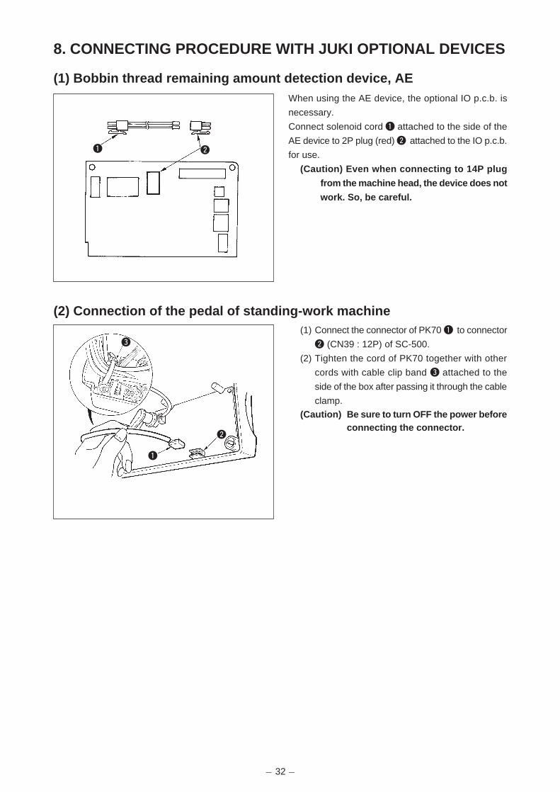
- 32 -
When using the AE device, the optional IO p.c.b. is
necessary.
Connect solenoid cord 1 attached to the side of the
AE device to 2P plug (red) 2 attached to the IO p.c.b.
for use.
(Caution) Even when connecting to 14P plug
from the machine head, the device does not
work. So, be careful.
21
3
1
2
(1) Connect the connector of PK70 1 to connector
2 (CN39 : 12P) of SC-500.
(2) Tighten the cord of PK70 together with other
cords with cable clip band 3 attached to the
side of the box after passing it through the cable
clamp.
(Caution) Be sure to turn OFF the power beforeconnecting the connector.
8. CONNECTING PROCEDURE WITH JUKI OPTIONAL DEVICES
(1) Bobbin thread remaining amount detection device, AE
(2) Connection of the pedal of standing-work machine

- 33 -
When the auto-lifter device (AK) is attached, this
function makes the function of auto-lifter work.
(1) Turn ON the power switch while pressing switch
3 inside the control box.
(2) LED display is turned to 5, 6 (FL ON) with
“beep”, and the function of auto-lifter becomes
effective.
(3) Turn OFF the power switch, and turn ON the
power switch again to return to the normal
mode.
(4) Repeat the operation 1) to 3), and LED display
is turned to (FL OFF). Then, the function of auto-
lifter does not work.
FL ON : Auto-lifter device becomes effective.
FL OFF : Auto-lifter function does not work.
(Standard at the time of delivery)
(Similarly, the presser foot is not automatically
lifted when programmed stitching is completed.)
(Caution) 1. To perform re-turning ON of the power, be sure to perform after the time of one second
or more has passed.
(If ON / OFF operation of the power is performed quickly, setting may be not changed
over well.)
2. Auto-lifter is not actuated unless this function is properly selected.
3. When “FL ON” is selected without installing the auto-lifter device, starting is
momentarily delayed at the start of sewing. In addition, be sure to select “FL OFF”
when the auto-lifter is not installed since the touch-back switch may not work.
56
3
2
1
(3) Setting of the auto lifter function
(1) Connect the connector of material end sensor
(ED) to connector 1(CN55 : 6P) of SC-500.
(2) Tighten the cord of the material end sensor
together with other cords with cable clip band
2 attached to the side of the box after passing
it through the cable clamp.
(Caution)
1. Be sure to turn OFF the power before
connecting the connector.
2. For the use of the material end sensor,
refer to the Instruction Manual attached
to the material end sensor.
(4) Connection of the material end sensor (ED)

- 34 -
1) Exclusive connectors are prepared for connection
of the connector for CP-160.
2) aying attention to the orientation of the connector
!2, connect it to connector !3 (CN38) located on
the circuit board. After connecting, securely lock the
connector.
!2
!3
(5) Connecting procedure of CP-160
9. EXTERNAL INPUT/OUTPUT CONNECTOR (SIGNAL CONNECTOR FOR EXTENSION)
For external input/output connector 8 , following
signals which are convenient when installing
counter or the like outside are prepared.
(Caution) When using the connector, consult
technic ians who have electr ical
knowledge.
8
Revolution by pedal is prohibited while “Low” signal is
being inputted.
Speed of rotation is limited to soft-speed while “Low”
signal is being inputted.
“Low” is output when needle bar is in its DOWN position.
“Low” is output when needle bar is in its UP position.
“Low” is output when sewing machine is in STOP state.
OV (Ground)
Rotation signal 45 pulses/revolution
Input signal of optional sub-panel switch.
Motion depends on setting of function setting No. 12.
OV (Ground)
Monitor LED output of SUBPSW
Table of layout of connector and signal
1
2
3
4
5
6
7
8
9
10
11
+5V
LSWINH(N)
SOFT(N)
DDET(N)
UDET(N)
S.STATE3(N)
SGND
HS(N)
SUBPSW(N)
SGND
SUBSWL(N)
-
Input
Input
Output
Output
Output
-
Output
Input
-
Output
Name ofsignal
CN40Pin No.
Input/output Description
DC5V,-5mA
DC5V,-5mA
DC5V
DC5V
DC5V
DC5V
DC5V,-5mA
DC5V,5mA
Electricity spec.

- 35 -
10. CONNECTOR CONNECTION DIAGRAM
Layout of CN36 pins by classified function Rev.
(1) Solenoid for machine head
Layout of the signals of machine head solenoid connectors CN36 and CN37 varies in accordance with the
function revision of CONTROL circuit board (CTL circuit board).
However, there is interchangeability for the specifications on the machine head side, and the signals can be
used without change.
CN36
TRMD
TRM COM
BTD
BT COM
WPD
WP COM
SUB BTD
SUB BT COM
UTSD
UTS COM
BTSW
BTSW RTN
N.C
FG
Name of signalPin No.Function Rev.01,02 Function Rev.03 and up
TRM COM
TRMD
BT COM
BTD
WP COM
WPD
SUB BT COM
SUB BTD
UTS COM
UTSD
BTSW RTN
BTSW
FG
FG
1
8
6
13
2
9
7
14
4
11
5
12
3
10
(2) Solenoid for lifting presser foot
FL (Presser foot lifter)
Approx. 5.4 Ω
CN37
CN37
Layout of CN37 pins by classified function Rev.
FLD
FL COM
Name of signalPin No.Function Rev.01,02 Function Rev.03 and up
FL COM
FLD
1
2
TRM (Thread trimming)Approx. 7.5 Ω
BT (Touch back)Approx. 6.5 Ω
WP (Wiper)Approx. 8.5 Ω
BT SW Touch back switch
CN36

- 36 -
Relay cord A asm. for the standing sewing machine
(Part No. M9701351AA0)
1) Wiring diagram of variable pedal PK-70 and -71
™ Power section A which is separated by respective signals with different colors comes out from the relay
cord A asm. for the standing sewing machine. Connect switches and variable resistor for speed in
accordance with the wiring diagram.
(Caution) Be sure to turn OFF the power before connecting the connector.
A
Approx. 1.5m
(3) Optional cord
Variable resistor for speed
Switch forlifting presser foot
Switch for threadtrimming
Switch forhigh-speed
Switch forlow-speed
Brown
Orange
Yellow
Green
Blue
Purple
Gray
White
Light blue
Pink
Black
Used by variable voltage
between 1 to 2V
(Increasing / decreasing
speed)
Neutral position is 1V ±0.05V
(Between 3 to 4)
CN39

- 37 -
3) Loosen setscrew 2 in front cover 1.
4) Pressing the side of front cover 1 in the
direction of the arrow, open the front cover
toward you.
(Note) Be sure to open / close the front cover
with your hands.
2) Wiring diagram of fixing max. speed
1) Press the OFF button of the power switch to
turn OFF the power after confirming that the
sewing machine has stopped.
2) Draw out the power cord coming from the power
plug socket after confirming that the power
switch is turned OFF. Perform the work of step
3) after confirming that the power has been cut
and it has passed for 5 minutes or more.
11. MAINTENANCE
(1) Replacing the fuse
12
Variable resistor for speed
Switch for lifting presser foot
Switch for thread trimming
Switch for high-speed
Switch for low-speed
Brown
Orange
Yellow
Green
Blue
Purple
Gray
White
Light blue
Pink
Black
CN39
(Caution) When decreasing the speed of the high-speed SW, use the max. speed limitation variableresistor on the panel.

- 38 -
F1
F2
F1
[ Replacing F1 fuse on CTL circuit board (solenoid protection fuse) ]
1) Loosen two setscrews in the front cover and
open the cover after checking that the power
has been turned OFF.
2) Replace 5A F1 fuse on CTL circuit board with a
fuse of the same capacity supplied as
accessories.
3) Close the front cover as before and fix it with
the setscrews while paying attention to pinching
of the cords.
[ Replacing F1 fuse on PWR circuit board (power circuit protection fuse) ]
[ Replacing F2 fuse on PWR circuit board (regenerative resistance protection fuse) ]
1) Loosen two setscrews in the front cover and
open the cover after checking that the power
has been turned OFF.
2) Remove connectors CN30, CN32, CN33,
CN36, CN37 and CN38 and remove the
setscrew attached to the ground wire of CTL
circuit board. (Connector Nos. depend on the
specifications.)
3) Draw up the front cover obliquely at the position
where the front cover is obliquely tilted by
approximately 45 degrees, and remove the
cover.
Remove the control box from the motor.
4) Remove four setscrews in the bottom cover and
remove the bottom cover.
5) Replace 3.15A F1 fuse or 2A F2 fuse on PWR
circuit board with a fuse of the same capacity
supplied as accessories.
6) Fix the bottom cover as before with the
setscrews, and press the front cover to the
bottom cover from the position where the front
cover is obliquely tilted by approximately 45
degrees for assembling.
7) Attach the connectors and the ground wire
which have been removed.
8) Close the front cover as before and fix it with
the setscrews while paying attention to pinching
of the cords.

- 39 -
(2) Changing procedure between 100V to 120V and 200V to 240V(Possible only for the voltage changeover type)
110V220V
110V
220V
220V
1
A
A
A
110V
Voltage can be changed between single phase 100 to 120V and single phase/3-phase 200 to 240V bychanging over the voltage changeover switch.
(Caution) The voltage changeover switch is on the inside of the control box. When changing the setting, besure to open the front cover after turning OFF the power switch and a lapse of 5 minutes or more.In addition, if the changing procedure is mistaken, the control box is damaged. So, be very careful.
(1) Turn OFF the power with the power switch afterchecking that the sewing machine has stopped.
(2) Draw out the power cord from the powerreceptacle after checking that the power switchhas been turned OFF. Then wait for 5 minutesor more.
(3) Remove two screws 1 fixing the front coverand slowly open the front cover.
(4) hanging procedure of the power voltage(Caution) When the voltage of the power
changeover switch and that of the AC inputcord are wrong, the control box is damaged.
Be sure to check the indication of thechangeover switch and the input powervoltage for use.
1) When using with 3-phase 200 to 240V¡Put a screwdriver or the like to the slit sectionA of the changeover switch and push up theswitch.(Indication of the voltage of switch is 220V.)
¡Connect the crimp style terminal of AC input cordto the power plug as shown in the figure A.
2) When using with single phase 200 to 240V¡Put a screwdriver or the like to the slit sectionA of the changeover switch and push up theswitch.(Indication of the voltage of switch is 220V.)
¡Connect the crimp style terminal of AC input cordto the power plug as shown in the figure B.
3) When using with single phase 100 to 120V¡ Put a screwdriver or the like to the slit section A of
the changeover switch and push down the switch.(Indication of the voltage of switch is 110V.)
¡Connect the crimp style terminal of AC input cordto the power plug as shown in the figure C.
(Caution) Be very careful that the components arenot damaged by the top end of the screwdriver.
(5) Check again that the change has beenperformed without fail before closing the frontcover.
(6) Close the front cover and tighten two screwswhile being very careful that the cord is notcaught by the cover.
WHITEBLACK
WHITEBLACK
RED
Plug side
GREEN/YELLOW
GREEN/YELLOW
RED
WHITEBLACK
Plug side
GREEN/YELLOW
RED
WHITEBLACK
Plug side
GREEN/YELLOW
RED
AC input cordVoltagechangeover switch
AC input cordVoltagechangeover switch
AC input cordVoltagechangeover switch
Fig. A
Fig. B
Fig. C
GREEN/YELLOW
GREEN/YELLOW
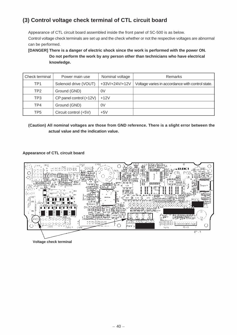
- 40 -
(3) Control voltage check terminal of CTL circuit board
Appearance of CTL circuit board assembled inside the front panel of SC-500 is as below.
Control voltage check terminals are set up and the check whether or not the respective voltages are abnormal
can be performed.
[DANGER] There is a danger of electric shock since the work is performed with the power ON.
Do not perform the work by any person other than technicians who have electrical
knowledge.
(Caution) All nominal voltages are those from GND reference. There is a slight error between the
actual value and the indication value.
Check terminal
TP1
TP2
TP3
TP4
TP5
Power main use
Solenoid drive (VOUT)
Ground (GND)
CP panel control (+12V)
Ground (GND)
Circuit control (+5V)
Nominal voltage
+33V/+24V/+12V
0V
+12V
0V
+5V
Remarks
Voltage varies in accordance with control state.
Appearance of CTL circuit board
Voltage check terminal

- 41 -
Phenomenon
When tilting the sewing machine, thebuzzer beeps and the sewingmachine cannot be operated.
Solenoids for thread trimming,reverse feed, wiper, etc. fail to work.Hand lamp does not light up.
Even when depressing the pedalimmediately after turning ON thepower, the sewing machine does notrun. When depressing the pedal afterdepressing the back part of pedalonce, the sewing machine runs.
The sewing machine does not stopeven when the pedal is returned toits neutral position.
Stop position of the sewing machinevaries (irregular).
Presser foot does not go up evenwhen auto-lifter device is attached.
Touch-back switch fails to work.
UP position move fails to work whenall lamps on the panel light up.
Sewing machine fails to run.
Cause
When tilting the sewing machine withoutturning OFF the power switch, Actiongiven on the left side is taken for safetysake.
When the fuse for solenoid powerprotection has blown out.
Neutral position of the pedal has varied.(Neutral position may be shifted whenchanging spring pressure of the pedalor the like.)
When tightening the screw in thehandwheel is forgotten at the time ofadjustment of needle stop position.
Auto-lifter function is OFF.
Pedal system is set to KFL system.
Cord of auto-l i f ter device is notconnected to connector (CN37).
Presser foot is going up by auto-literdevice.
Auto-lifter device is not attached.However, auto-lifter function is ON.
The mode is in the function setting mode.The switch on the CTL p.c.b. is pressedb y t h e b o u n d c o r d s a n d t h eaforementioned mode resulted.
Motor output cord (4P) is disconnected.
Connector (CN30) of motor signal cordis disconnected.
Corrective measure
Tilt the sewing machine after turning OFFthe power.
Check the fuse for solenoid powerprotection.
Execute the automatic neutral correctionfunction of the pedal sensor.
Securely t ighten the screw in thehandwheel.
Select “FL ON” by auto-lifter functionselection.
Change the jumper to PFL setting to liftthe presser foot by depressing the backpart of the pedal.
Connect the cord properly.
Operate the switch after the presser footlowered.
Select “FL OFF” when auto-lifter device isnot attached.
Remove the front cover, and arrange thecords by the regular binding proceduredescribed in the Instruction Manual.
Connect the cord properly.
Connect the cord properly.
In case of the following, check again before you judge the case as trouble.
12. ERROR CODES
In addition, there are the following error codes in this device. These error codes interlock (or limit function) and inform the problem sothat the problem is not enlarged when any problem is discovered. When you request our service, please confirm the error codes.
Checking procedure of the error code1) Pressing switch 1 in the control box, turn ON the power
switch.2) LED becomes display 5 with the sound of “peep”
and the latest error code is displayed.3) Confirmation of the contents of previous error can
be performed by operating switches 1 or 2.
(Caution) When operating switch 1, one before theexisting error code is displayed.
When operating switch 2, one after theexisting error code is displayed.
5
1 2

- 42 -
(1) Error code list
No.
E000
E003
E004
E005
E007
E008
E343
E730
E731
E811
E813
E906
E924
Description of error detected
Execution of data initialization
(This is not the error.)
Disconnection of synchronizer
connector
Synchronizer lower position
sensor failure
Synchronizer upper position
sensor failure
Overload of motor
Machine head connector
failure(Resistance pack)
Bobbin thread remaining
amount sensor unit failure
Encoder failure
Motor hole sensor failure
Overvoltage
Low voltage
Operation panel transmission
failure
Motor driver failure
Cause of occurrence expected
• When the machine head is changed.
• When the initialization operation is executed
• When position detection signal is not input
from the sewing machine head synchronizer.
• When the synchronizer has broken.
• When the machine head is locked.
• When sewing extra-heavy material beyond
the guarantee of the machine head.
• When the motor does not run.
• Motor or driver is broken.
• When the machine head connector is not
properly read.
• When the position of the detection bar of
the AE device is shifted from the home
position.
• When the motor signal is not properly
inputted.
• When voltage higher than guaranteed one
is inputted.
• 220V has been inputted to SC-500 of 110V
specifications.
• 400V is applied to the box of 220V (230V).
• When voltage lower than guaranteed one
is inputted.
• 110V has been inputted to SC-500 of 220V
specifications.
• 110V is applied to the box of 220V.
• Inner circuit is broken by the applied
overvoltage
• Disconnection of operation panel cord
• Operation panel has broken.
• Motor driver has broken.
Items to be checked
• Check the synchronizer connector (CN33) for
loose connection and disconnection.
• Check whether the synchronizer cord has broken
since the cord is caught in the machine head.
• Check whether the thread has been entangled in
the motor pulley.
• Check the motor output connector (4P) for loose
connection and disconnection.
• Check whether there is any holdup when turning
the motor by hand.
• Check the machine head connector (CN32) for
loose connection and disconnection.
• Check whether the detection bar of the AE device
has returned to the correct position.
• Check whether the function setting No. 57 has
been mistakenly set.
• Check the AE device connectors (CN121, CN123)
for loose connection and disconnection.
• Check whether the AE device cord has broken
since the cord is caught in the machine head.
• Check the motor signal connector (CN30) for loose
connection and disconnection.
• Check whether the motor signal cord has broken
since the cord is caught in the machine head.
• Check whether the applied power voltage is higher
than the rated voltage + (plus) 10% or more.
• Check whether 110V/220V changeover switch is
improperly set.
• In the aforementioned cases, POWER p.c.b is
broken.
• Check whether the voltage is lower than the rated
voltage – (minus) 10% or less.
• Check whether 110V/220V changeover switch is
improperly set.
• Check whether fuse or regenerative resistance is
broken.
• Check the operation panel connector (CN38) for
loose connection and disconnection.
• Check whether the operation panel cord has
broken since the cord is caught in the machine head.

- 43 -
* A,E: 40016493 PSC UNIT A ASSY* B: 40016494 PSC UNIT B ASSY* C: 40016495 PSC UNIT C ASSY* D: 40018367 PSC UNIT D ASSY
13. BLOCK DIAGRAM
M50
* B: 40018481 E50 COMPLETE* A,E: 40018482 E50 COMPLETE JUS* C: 40018483 E50 COMPLETE JE* D: 40018484 E50 COMPLETE CN
4P
2P2P
2P2P
* A,E:40016522VOLTAGE SELACT CORD ASSY
40006134RESISTANCE A ASSY
* A: M6101471AA0 POWER SWITCH A ASM* B,D: M6101471CA0 POWER SWITCH C ASM
4P 4P
CN41(OPTIONAL P.C.B. I/F)
CN34(PEDAL SENSOR)
CN39(STAND PEDAL)
CN38(CP-160)
* A,ECN1(110V/220V CHANGEOVER)
CN2(REGERATIVE RESISTANCE)
T3-1T3-2T3-3
CN141
CN4(+5V, EACH CONTROL SIGNAL)
CN3(VOUT +33Vor+24Vor+12V)
T15-3T15-1T15-2
* A,E: 40016465 PWR PCB A ASSY* B,D: 40016466 PWR PCB B ASSY* C: 40016467 PWR PCB C ASSY
* C: M6102461DAAPOWER INPUT CABLE CE ASM
* C: 40006139POWER INPUT CABLE D ASM
* E: 40012009POWER INPUT CABLE LA ASM
4P4P
4P
(MOTOR DRIVE)
20P
12P
20P
4P4P
30P
40016471PEDAL SENSOR UNIT C ASSY
* OP:CP-160 PANEL 9P 9P
4P7P
2P2P7P
4P
14P
14P
11P
CN140
CN40(USER EXTENSION SIGNAL)
CN36(HEAD MAGNET DRIVE)
CN37(FL)
CN33(SYNCHRONIZER)
CN32(HEAD DISCRIMINATION)
CN30(ENCODER)
40012423CTL PCB ASSY
CN31 CN35
26P
26P
26P
26P
40016468I/F CABLE ASSY
40016469DC POWER SUPPLY CORD ASSY
4P
4P
4P
4P
Symbol
A
B
C
D
E
Destination
JUS
JS
JE
CN
JUS
“* SYMBOL” in the diagram indicates the selective parts for the classified destination.No mark is used for all destinations. In addition, “*OP:” indicates optional selective parts.
Name of electric equipment complete set
SC500 1/3PHASE 120/240 PFL
SC500 1PHASE 200/240 PFL
SC500 1PHASE 230 PFL CE
SC500 1PHASE 220 PFL CN
SC500 1PHASE 100-120 PFL LA
Part No. of complete set
40016490
40016491
40016492
40018366
40018385

- 44 -
100
14. DRAWING OF THE TABLE (For DDL-8700)
U-U
S-S
W-W
V-V (1:1) X-X Y-Y Z-Z T-T
Y - Yrubber cushion installing
drawing for reference
X - Xrubber cushion installing
drawing for reference
Installing position of stopper fordrawer (on the reverse side)
4 - ø 3.4 on the bottom surface, depth 20
(Drill a hole at the time of set-up.)
JUKIlogotype
C1.5 to C2.5(For the hinge side only)
Measure detailed drawing (2 : 1)
Style : Helvetica Reg. CondensedCondensed voided letters
2-ø3.5 depth 4
2-ø3.5 depth 4
3-ø13 drilled hole
2-ø13 depth 10
ø16 depth 30
ø35 ± 0.5 drilled hole
2-ø 3.4 on the bottom surface, depth 10(Drill a hole at the time of set-up.)
2-ø3.5 depth 10
1200
810225
5075 18
ø18 drilled hole
5725.5107
*47±1
28
80
80 (72.2) 339.7±1
52
75.5±0.1
14 968.1±0.5
90 52.5195 100
125 40
195
300
480
500
(525)
(591)
(21) 50 2040
91
390
10
(244
)18
10
136
(22.
5)22
.5
29
140
101
29
95±2
4333
±1 50.5
±1
21.5
8421
.5
86.5
360
70(1
40)
195
200
535
27.5
5517 40
139
14
10
21+0.50
40
27
6
ø26
ø8.5
1
8
17.5
±0.5
23.5
±0.5
19.5
±0.5
1±0.
5
711
.5 7.5
7.5
0.5
0.8 1 1 0.8
11
120˚ 5 x 160 = 800
Thickness : 1.5
Thickness : 0.8
Thickness : 0.5
Thickness : 1.5
R30
R30
R2
R2
R2
R30
R2
C1 C1
R2
R2
R30
R2
R2R27.5
R2
R2
R30
R30
R2
R2R30
50
R8
R242.5
R8
R8
R10
R10
R20
R22
.5
R8
R8
R242.5
12±1
R18R22.5
R8 R8
R10
R10
R22.5
R20
R30
R30
R22.5R18
110
R6
5-R1
1.2±
0.5
1.2±0.5
V V
U
U
Y
Y
Z
Z
X
X
S
W W
90
S
R8
80
R6
R2
159
Part No. : 11155603
T
T
66.5
P27.
5
20+0.50
141
188
-1

Please do not hesitate to contact our distributors or agents in your area for further information when necessary.* The description covered in this engineer's manual is subject to change for improvement of the
commodity without notice.
03 · 11 Printed in Japan (E)
R
INTERNATIONAL SALES H.Q.8-2-1, KOKURYO-CHO,CHOFU-SHI, TOKYO 182-8655, JAPANPHONE : (81)3-3430-4001 to 4005FAX : (81)3-3430-4909 • 4914 • 4984TELEX : J22967
Copyright C 2003 JUKI CORPORATION.
All rights reserved throughout the world.