Embed Size (px)
Citation preview
1
R- RH- and RHC-Steam Boiler Models (RB-Series)
Instructions Manual
Electra Steam, Inc.
P.O. Box 37 Phone: 540-662-3811 4407 Martinsburg Pike Fax: 540-665-8101 Clear Brook, VA 22624 email: [email protected] USA web: www.reimersinc.com
2008 Reimers Electra Steam, Inc. Rev. 1
_____
MODEL:
__________
SERIAL #:

2
READ AND HEED FOR YOUR SAFETY
SHOCK AND BURN WARNINGS R, RH and RHC ELECTRIC STEAM BOILERS You have just purchased a quality steam boiler designed to the ASME Boiler Code and registered with theNational Board of Boiler Inspectors. Treat this industrial equipment with care and respect. It is safe when installed,maintained, and used properly. Read the instruction carefully, refer to the enclosed identification photo andcontact the factory if you have any questions. 1.) ADJUSTMENTS: All controls have been set at the factory and should require no adjustments. However, the boiler must be level. 2.) BLOWDOWN VALVE: This valve is utilized to blow impurities from the boiler chamber. When opened, a large volume of hot water andsteam is discharged. Ensure that this valve is properly piped for such discharge. State and local codes must bemet as applicable. 3.) ELECTRICAL: All wiring must be in accordance with the National Electric Code and any local codes that may apply. Wiring mustbe made by a competent certified electrician. Use copper wire only. 4.) GAUGE GLASS: The gauge glass protector guard must be on at all times. When replacing glass be sure that the unit is not underpressure and is cool to touch. To do otherwise could cause scalding. GAUGE GLASSES SHOULD BE REPLACED ANNUALLY DUE TO INTERNAL WEAR! HOT: The valves and piping on this unit are hot when under pressure or heating up. Don’t touch. 5.) INSTRUCTIONS: Read instructions before installing or operating this steam boiler. These are provided as general guidelines. 6.) MODIFICATION/MISUSE: This boiler has been designed and constructed in accordance with the ASME Boiler Code. Any modification ormisuse can result in a dangerous situation. Reimers Electra Steam, Inc. is not liable for any product that has beenmodified or improperly used. 7.) PRESSURE GAUGE: The pressure gauge indicates the internal pressure of the boiler. It can fail. Periodicallyhave your boiler inspector compare the gauge with a known gauge utilizing the test valve arrangement provided.Ensure that the boiler is cold, not pressurized and electrically disconnected. 8.) REGISTRATION: Most states and cities require boiler registration and inspection. Check with your government authorities. 9.) REPAIR: Repair of this unit must be attempted only by experienced personnel. Before commencing a repair, ensure thatthe boiler is cold, not pressurized and electrically disconnected. All standard electrical and steam safetyprecautions must be taken during testing. 10.) SAFETY VALVE: The safety valve is designed to discharge hot steam when the set pressure is exceeded. Ensure that thedischarge port is pointing toward the back of the unit away from the operator or any aisles. Test the safety valveperiodically to ensure that it is operating properly. Test carefully at full pressure by lifting lever using pliers and“slapping” shut. STEAM DISCHARGE CAN SCALD. ENSURE NO ONE IS EXPOSED! 11.) STEAM INSTALLATION: Steam piping must be of black pipe, not galvanized. Work must be done by an experienced steam fitter. All state and local codes must be met as applicable. 12.) WATER: Ensure that all electrical components are in a dry location, free from any possibility of water soaking. Electric footswitches must not be placed on a wet floor. They must be placed on dry surface not subject to steam or water.
3
LIMITED WARRANTY - STEAM BOILERS
Reimers Electra Steam, Inc. warrants the following products of its own manufacture against defects in materials and workmanship under normal use and service. This warranty is in lieu and excludes all other expressed or implied warranties or merchantability of fitness for any particular use. No person is authorized to extend the terms of this warranty or assume any other liability except by written statement signed by an officer of Reimers Electra Steam, Inc. Clear Brook, Virginia 22624.
WARRANTY PERIOD The pressure vessel, electrical and mechanical components are warranted for one year from date of shipment from Reimers Electra Steam, Inc. in Clear Brook, VA 22624.
LIMITATIONS Products must be installed, used and maintained in accordance with our instructions, including reasonable and necessary maintenance by the user. Users are responsible for the suitability of the products to their application. There is no warranty damage resulting from improper installation, abuse, power failure, fire, flood, lightening, improper water, misuse, improper specification, misapplication or other operating conditions beyond our control or parts that are normally expendable in usual course of operation. Claims against carriers for damage in transit must be filed by the buyer. Reimers liability, if any, will not exceed the price of Reimers products claimed to be defective. Components manufactured by any supplier other than Reimers shall bear only that warranty made by the manufacturer of that product and service for that warranty shall be the responsibility of that manufacturer and not Reimers.
REMEDY Claims under this Limited Warranty must be made by obtaining a Return Authorization Number from our office (PHONE: 540-662-3811,FAX: 540-665-8101) and returning defective part, freight prepaid to: Reimers Electra Steam, Inc., 4407 Martinsburg Pike, Clear Brook, Virginia 22624. Defective items will be repaired or replaced as necessary within a reasonable time without charge, other than incidental charges such as freight prepayment. Such repair or replacement within a reasonable time is the exclusive remedy available from Reimers Electra Steam, Inc., under this Limited Warranty.
CONSEQUENTIAL DAMAGES Reimers Electra Steam, Inc., is not liable for labor costs incurred in the removal, reinstallation, or unauthorized repair of product, or for damages of any type whatsoever, including incidental and/or consequential damages.
THIS WARRANTY SUPERSEDES ALL PREVIOUS WARRANTIES.
4
1. Installation
REIMERS ELECTRA STEAM, INC., boilers are heated by one or more immersion type heating elements. Automatic controls are provided to maintain pre-set operating pressure and proper water supply. Safety features include automatic low water cutoff, automatic pressure control, safety valve and visible water level gauge. Each boiler is manufactured in accordance with ASME I Power Boiler Code Standards and is individually inspected and stamped by an authorized National Board Insurance Inspector. All boilers are registered with the National Board of Boiler and Pressure Vessel Inspectors.
NOTE: ASME DATA PLATE IS LOCATED ON END OF PRESSURE VESSEL
BEHIND LABEL STAMPED WITH NATIONAL BOARD NUMBER OF UNIT. When boiler is received, make sure it has not been damaged in shipment. 1.1 Location
Place the boiler in a level position, close to the equipment which it is to supply. This will insure minimum heat losses and allow more economical piping arrangements. All steam lines should be insulated. 1.2 Water Supply
R, RH and RHC steam boiler models require four (4) gallons of feed water per hour for each 10 kW of electric heating capacity of the boiler. Lines should be of adequate size and meet local plumbing codes. All boilers must be blown down periodically to remove minerals, scale and other foreign matter, which accumulate inside the pressure vessel. The concentration of this deposit depends in part upon the condition of the water in the area. When water is naturally soft, or has been softened chemically, boiler blowdowns are required less often than in areas where hard water is found. Water *softeners are suggested in hard water areas to minimize the formation of hard scale on heating elements. Another factor affecting water condition is the amount of condensate, if any, that is being returned to the boiler. Since condensate is essentially clean distilled water, it contains very few impurities. If a large part of the condensate is being returned and little make-up water is used, the boiler need not be blown down as often as when little or no condensate is returned to the boiler. Chemical water treatment is not recommended for this design of electric boiler except as follows: Recommended water quality by ABMA (American Boiler Manufacture’s Association)
Total dissolved solids 3500ppm max Suspended solids 300ppm max Total Alkalinity 700ppm max PH > 8.5
The above values are also referenced in Marks’ handbook. Following our research, we are concerned with hardness, PH and suspended solids. Feed water can be filtered, softened and adjusted for PH prior to entering boiler. Our recommendations are:
PROPERTIES TREATMENT Hardness less than 17ppm (1 grain) Ion exchange water softener PH between 10 and 11.5 Consult water treatment expert for PH inducer Suspended Solids less than 300ppm Consult water treatment expert for filter Note: Our electronic water level controls require a specific resistivity not greater than 25KΩ/CM The recommendations we make do not guarantee no water related problems. There are many factors, which affect water quality which we can not evaluate. *For details, contact a water softening company in your area. Blowdown is an essential part of boiler operation. It is the best preventive maintenance you can give your boiler. Ensure a blowdown schedule is established and followed regularly.

5
1.3 Steam Outlet
Connect steam line of sufficient size from steam outlet valve to the user’s equipment. 1.4 Condensate Return
If the condensate is to be returned by gravity (no tank) in a closed system, the load discharge should be at least 2 feet above the boiler level so that the weight of the condensate will actuate the check valve. When applicable, install steam return lines at sufficient height to allow a pitch of 2 inches for every 10 feet of pipe length. Note: For condensate return systems (with tank), see Instruction Supplement 1 in this manual. 1.5 Safety Valve
If it is required that discharge piping be installed from the safety valve, the pipe should not be smaller than the valve outlet and should be rigidly supported so as not to place weight on the valve itself. Important: No valve in this line!
1.6 Electrical
Install a fused disconnect switch near the boiler. It should be fused as marked on the boiler name plate. Connect the power supply from the disconnect switch to the terminals in the boiler control panel. A copy of the wiring diagram is in the control panel. Important: Electrical connections to the boiler control panel (FIG. 7) should be made by a qualified Electrician. All wiring must comply with local electrical codes.
2. Operation
2.1 Basic Operations a.)
b.) Throw fused disconnect switch (not provided by factory) to on position and turn on boiler control voltage
c.) Open feed water shutdown valve
Close blowdown valve
Open gauge glass
Open steam line valveslightly. This will allow theboiler to be filled withoutproducing back pressure.
Figure 1
Figure 2

6
d.)
e.)
f.) To shut off boiler: Turn the POWER switch on the boiler controller off.
Turn POWER switch on
Turn BLOWDOWN ENABLE switch off.
After approximately 2 seconds, WATER FEEDlight turns on and water enters boiler. As soon aswater level reaches approximately half height ofgauge glass, automatic water feed turns off. Caution: Do not leave the pump to run dry!
If the boiler controller indicates any boiler alarms, then press the corresponding alarm reset switch.
As soon as no boiler alarms are indicated, the HEATING light turns on and the boiler starts to build up pressure.
Close the steam line valve.
Observe pressure gauge while pressure builds up,until working pressure is reached. The workingpressure should have been factory set to yourspecification. However, if you wish to change theworking pressure setting, proceed as follows:
Remove the cover from the pressure control enclosure. This gives access to the boiler pressure controls.
Turn the black knob of this pressure controlclockwise to increase and counterclockwise to decrease the boiler working pressure. Do not adjust the upper and, if provided, the lower pressure controls.
Figure 3
Figure 4
Figure 5
7
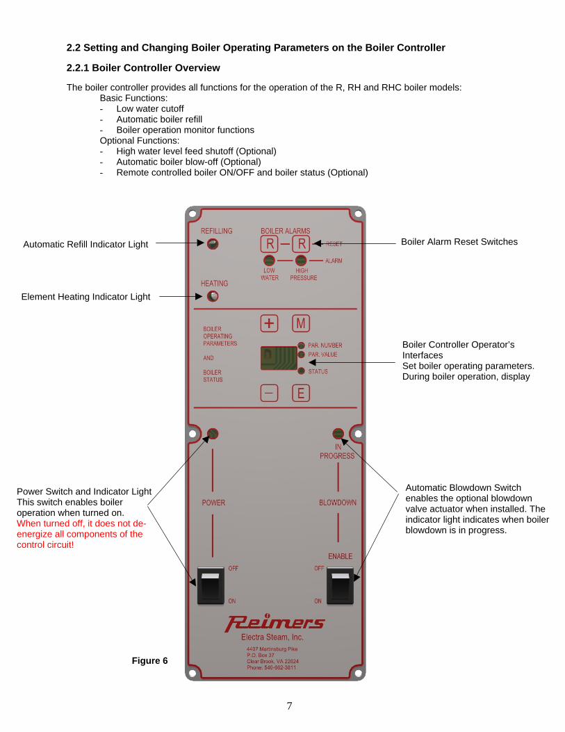
2.2 Setting and Changing Boiler Operating Parameters on the Boiler Controller 2.2.1 Boiler Controller Overview The boiler controller provides all functions for the operation of the R, RH and RHC boiler models: Basic Functions:
- Low water cutoff - Automatic boiler refill - Boiler operation monitor functions Optional Functions: - High water level feed shutoff (Optional) - Automatic boiler blow-off (Optional) - Remote controlled boiler ON/OFF and boiler status (Optional)
Automatic Refill Indicator Light Boiler Alarm Reset Switches
Element Heating Indicator Light
Boiler Controller Operator’s Interfaces Set boiler operating parameters. During boiler operation, display
Automatic Blowdown Switch enables the optional blowdown valve actuator when installed. The indicator light indicates when boiler blowdown is in progress.
Power Switch and Indicator Light This switch enables boiler operation when turned on. When turned off, it does not de-energize all components of the control circuit!
Figure 6
8
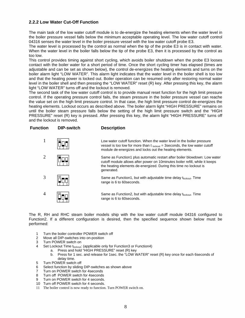
2.2.2 Low Water Cut-Off Function
The main task of the low water cutoff module is to de-energize the heating elements when the water level in the boiler pressure vessel falls below the minimum acceptable operating level. The low water cutoff control 04316 senses the water level in the boiler pressure vessel with the low water cutoff probe E3. The water level is processed by the control as normal when the tip of the probe E3 is in contact with water. When the water level in the boiler falls below the tip of the probe E3, then it is processed by the control as too low. This control provides timing against short cycling, which avoids boiler shutdown when the probe E3 looses contact with the boiler water for a short period of time. Once the short cycling timer has elapsed (times are adjustable and can be set as shown below), the control de-energizes the heating elements and turns on the boiler alarm light “LOW WATER”. This alarm light indicates that the water level in the boiler shell is too low and that the heating power is locked out. Boiler operation can be resumed only after restoring normal water level in the boiler shell and then pressing the “LOW WATER” reset (R) key. After pressing this key, the alarm light “LOW WATER” turns off and the lockout is removed. The second task of the low water cutoff control is to provide manual reset function for the high limit pressure control. If the operating pressure control fails, the steam pressure in the boiler pressure vessel can reache the value set on the high limit pressure control. In that case, the high limit pressure control de-energizes the heating elements. Lockout occurs as described above. The boiler alarm light “HIGH PRESSURE” remains on until the boiler steam pressure falls below the setting of the high limit pressure switch and the “HIGH PRESSURE” reset (R) key is pressed. After pressing this key, the alarm light “HIGH PRESSURE” turns off and the lockout is removed.
Function DIP-switch Description
1 Low water cutoff function. When the water level in the boiler pressure vessel is too low for more than t lockout = 3seconds, the low water cutoff module de-energizes and locks out the heating elements.
2 Same as Function1 plus automatic restart after boiler blowdown: Low water cutoff module allows after power on 10minutes boiler refill, while it keeps the heating elements de-energized. During this time no lockout is generated.
3 Same as Function1, but with adjustable time delay tlockout. Time range is 6 to 60seconds.
4 Same as Function2, but with adjustable time delay tlockout. Time range is 6 to 60seconds.
The R, RH and RHC steam boiler models ship with the low water cutoff module 04316 configured to Function2. If a different configuration is desired, then the specified sequence shown below must be performed:
1 Turn the boiler controller POWER switch off 2 Move all DIP-switches into on-position 3 Turn POWER switch on 4 Set Lockout Time tlockout: (applicable only for Function3 or Function4)
a. Press and hold “HIGH PRESSURE” reset (R) key b. Press for 1 sec. and release for 1sec. the “LOW WATER” reset (R) key once for each 6seconds of
delay time. 5 Turn POWER switch off 6 Select function by sliding DIP-switches as shown above 7 Turn on POWER switch for 4seconds 8 Turn off POWER switch for 4seconds 9 Turn on POWER switch for 4 seconds. 10 Turn off POWER switch for 4 seconds. 11 The boiler control is now ready to function. Turn POWER switch on.
1 2 3
on
1 2 3
on
1 2 3
on
1 2 3
on

9
2.2.3 Setting Boiler Operating Functions, Monitors and Parameters
Example: The Boiler Function Configuration “0” selected above indicates that the following boiler functions are enabled: “Automatic boiler refill function with single probe (E1)” with function parameters
“Refill ON-delay time”= 0seconds (PAR. NUMBER 20) “Refill OFF-delay time” = 3seconds (PAR. NUMBER 21)
And “Pressure Controlled boiler blowdown function” with function parameter “Blowdown duration” = 10minutes (PAR. NUMBER 31) Please refer to Table1 for all available function configurations and detailed boiler function descriptions. The Boiler Monitor Configuration “0” selected above indicates that the following boiler monitors are enabled: “Automatic boiler refill monitor” with parameters “Initial automatic boiler refill timeout after power-on = 10minutes (PAR. NUMBER22) “Automatic boiler refill timeout during boiler operation 1minutee (PAR. NUMBER23) And “Boiler high water level cut-off monitor” Please refer to Table2 for all available boiler monitor configurations and their detailed description. In order to make changes to the boiler controller configuration, proceed as follows: a.) Before setting parameters, a pass code must be entered. This keeps unauthorized personnel from changing controller configurations. In order to enter the pass code, follow the steps below: While the power switch is in ON-position, and the “STATUS”-LED is lit, press and hold the <-> and <E> keys at the same time. With <-> and <E> keys pressed, enter the following sequence on the <+> and <M> keys: <+>, <M>, <+>, <+> and <M>. Once the code is entered correctly, the light on the menu-LED’s toggles from “STATUS” to “PAR. NUMBER” and the controller is ready for boiler operating parameter changes.
With <-> and <E> pressed, enter: <+>, <M>, <+>, <+> and <M>
Press and hold these keys
R, RH and RHC boiler models usually ship with the boiler controller configuredset as shown. No adjustments to the boiler controller need to be made inorder to operate the boiler.
The left display digit indicates the selected boiler function configuration,whereas the right display digit indicates the boiler monitoring configuration.
Boiler Function Configuration
Boiler Monitor Configuration

10
b.) Press the <+> and/or <-> keys to set the boiler operating parameter number. When the parameter number is set, press the <M> key. This will toggle the light on the menu-LED’s from “PAR. NUMBER” to “PAR. VALUE” and the controller is ready for the selected boiler operating parameter value to be set.
c.) Press the <+> or <-> key to set the selected boiler operating parameter value.
d.) To set the next boiler operating parameter, press the <M> key. Repeat item b.) and c.) until all required boiler operating parameters are set.
e.) To exit the boiler parameter setting menu, press the <E> key. Once the <E> key is pressed, the light toggles from the “PAR. VALUE”-LED to the “STATUS”-LED and the new boiler status is displayed.
Set parameter number
Set parameter number
Set parameter value
Set parameter value
Press <M>

11
The following Tables provide an overview of all available boiler and monitor function configurations (Table1 and Table2). Table 3 provides an overview of all operating parameters used in the boiler and monitor functions. Table 1: Boiler Function Configurations
PAR. NUMBER
PAR. VALUE
PARAMETER DESCRIPTION
0 Boiler-Functions Configuration 0 disabled. 0 1 Boiler-Functions Configuration 0 enabled = “0” displayed in left digit of LED-Display.
]
- Automatic boiler refill function with single probe (E1), refill ON-delay time = 0seconds, refill OFF-delay time = 3seconds.
- Pressure controlled boiler blowdown function (Automatic Flush & Drain) with blowdown duration = 10minutes. (Enable/disable this function with BLOWDOWN ENABLE switch on boiler controller)
0 Boiler-Functions Configuration 1 disabled. 1 1 Boiler-Functions Configuration 1 enabled = “1” displayed in left digit of LED-Display
- Automatic boiler refill function with single probe (E1), refill ON-delay time = 0seconds, refill OFF-delay time = 10seconds.
- Pressure controlled boiler blowdown function (Automatic Flush & Drain) with blowdown duration = 10minutes. (Enable/disable this function with BLOWDOWN ENABLE switch on boiler controller)
0 Boiler-Functions Configuration 2 disabled. 2
1 Boiler-Functions Configuration 2 enabled = “2” displayed in left digit of LED-Display
- Automatic boiler refill function with single probe (E1), refill ON-delay time = PAR. NUMBER20 (0 – 10seconds), refill OFF-delay time = PAR. NUMBER21 (3 – 11seconds).
- Pressure controlled boiler blowdown function (Automatic Flush & Drain) with blowdown duration = PAR. NUMBER31. (1 - 20 minutes), (Enable/disable this function with BLOWDOWN ENABLE switch on boiler controller)
0 Boiler-Function Configurations 3 - 9 disabled. 3 - 9 1 Boiler-Function Configuration 3 - 9 enabled: No functions implemented yet.
Boiler Function Definitions Automatic boiler refill function with single probe (E1) Sequence of Events:
- As soon as the POWER switch on the boiler controller is turned off, the boiler controller de-energizes the boiler feed water pump and/or solenoid valve.
- If the POWER switch is turned on: o As long as the water level-probe (E1) is in contact with the boiler water, the boiler controller keeps the boiler
feed water pump and/or solenoid valve de-energized. o As soon as the water level-probe (E1) looses contact with the boiler water, the boiler controller energizes the
boiler feed water pump and/or solenoid valve after the elapse of the refill ON-delay time (PAR. NUMBER20). o As soon as the water level-probe makes contact with the boiler water, the boiler controller de-energizes the
boiler feed water pump and/or solenoid valve after the elapse of the refill OFF-delay time (PAR. NUMBER21). Pressure controlled boiler blowdown function This function requires the Blowdown Valve Actuator and Blowdown Enable Pressure Control installed on the boiler. Sequence of Events:
- As soon as the POWER switch on the boiler controller is turned on, the boiler controller de-energizes the Blowdown Valve Actuator (B2).
- With POWER switch turned off and as soon as the boiler pressure falls below the setting of the Blowdown Enable Pressure Control (S5), the boiler controller generates a 6second time delay. As soon as this time delay has elapsed, the boiler controller energizes (opens) the Blowdown Valve Actuator (B2) for a time (in minutes) saved in PAR. NUMBER31.
- After the time saved in PAR. NUMBER31 has elapsed, the boiler controller de-energizes (closes) the Blowdown Valve Actuator (B2).
12
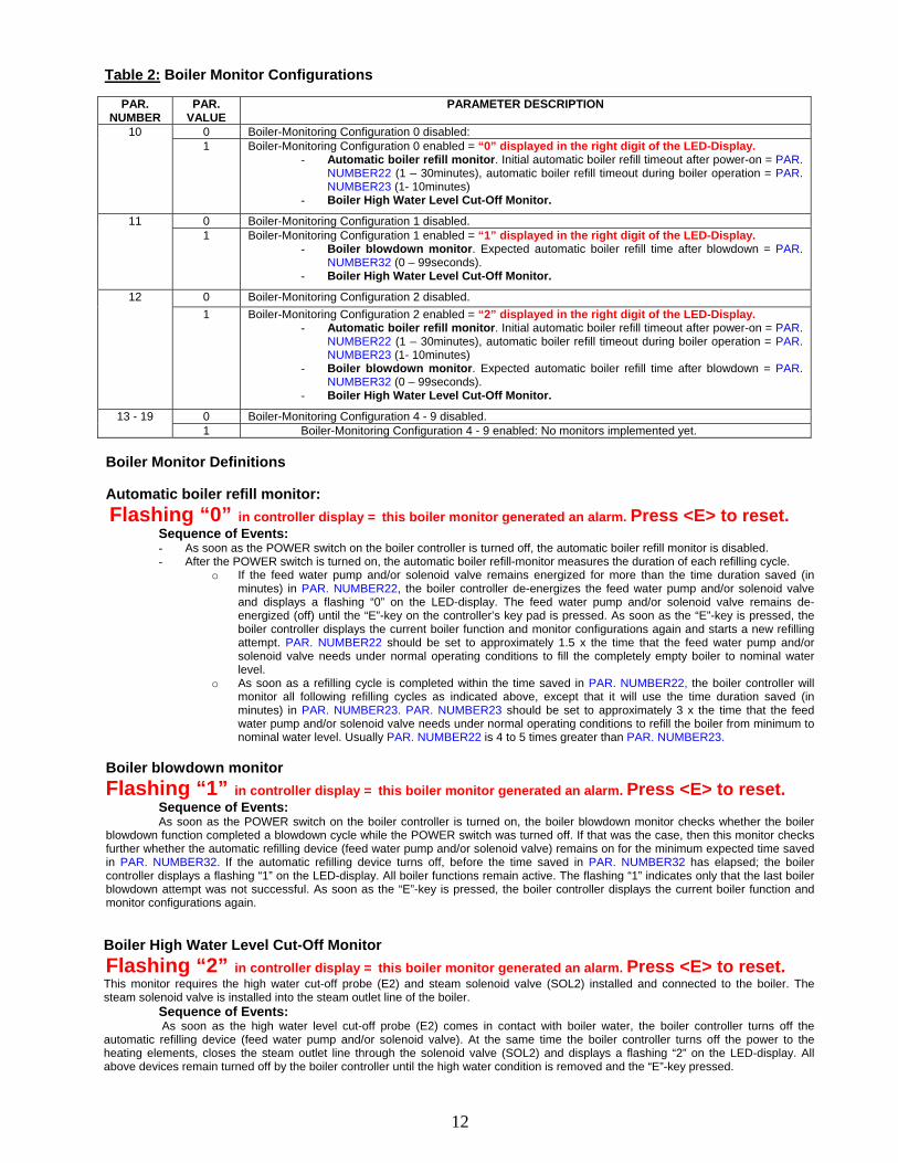
Table 2: Boiler Monitor Configurations
PAR.
NUMBER PAR.
VALUE PARAMETER DESCRIPTION
0 Boiler-Monitoring Configuration 0 disabled: 10 1 Boiler-Monitoring Configuration 0 enabled = “0” displayed in the right digit of the LED-Display.
- Automatic boiler refill monitor. Initial automatic boiler refill timeout after power-on = PAR. NUMBER22 (1 – 30minutes), automatic boiler refill timeout during boiler operation = PAR. NUMBER23 (1- 10minutes)
- Boiler High Water Level Cut-Off Monitor.
0 Boiler-Monitoring Configuration 1 disabled. 11 1 Boiler-Monitoring Configuration 1 enabled = “1” displayed in the right digit of the LED-Display.
- Boiler blowdown monitor. Expected automatic boiler refill time after blowdown = PAR. NUMBER32 (0 – 99seconds).
- Boiler High Water Level Cut-Off Monitor.
0 Boiler-Monitoring Configuration 2 disabled. 12 1 Boiler-Monitoring Configuration 2 enabled = “2” displayed in the right digit of the LED-Display.
- Automatic boiler refill monitor. Initial automatic boiler refill timeout after power-on = PAR. NUMBER22 (1 – 30minutes), automatic boiler refill timeout during boiler operation = PAR. NUMBER23 (1- 10minutes)
- Boiler blowdown monitor. Expected automatic boiler refill time after blowdown = PAR. NUMBER32 (0 – 99seconds).
- Boiler High Water Level Cut-Off Monitor.
0 Boiler-Monitoring Configuration 4 - 9 disabled. 13 - 19 1 Boiler-Monitoring Configuration 4 - 9 enabled: No monitors implemented yet.
Boiler Monitor Definitions Automatic boiler refill monitor: Flashing “0” in controller display = this boiler monitor generated an alarm. Press <E> to reset. Sequence of Events:
- As soon as the POWER switch on the boiler controller is turned off, the automatic boiler refill monitor is disabled. - After the POWER switch is turned on, the automatic boiler refill-monitor measures the duration of each refilling cycle.
o If the feed water pump and/or solenoid valve remains energized for more than the time duration saved (in minutes) in PAR. NUMBER22, the boiler controller de-energizes the feed water pump and/or solenoid valve and displays a flashing “0” on the LED-display. The feed water pump and/or solenoid valve remains de-energized (off) until the “E”-key on the controller’s key pad is pressed. As soon as the “E”-key is pressed, the boiler controller displays the current boiler function and monitor configurations again and starts a new refilling attempt. PAR. NUMBER22 should be set to approximately 1.5 x the time that the feed water pump and/or solenoid valve needs under normal operating conditions to fill the completely empty boiler to nominal water level.
o As soon as a refilling cycle is completed within the time saved in PAR. NUMBER22, the boiler controller will monitor all following refilling cycles as indicated above, except that it will use the time duration saved (in minutes) in PAR. NUMBER23. PAR. NUMBER23 should be set to approximately 3 x the time that the feed water pump and/or solenoid valve needs under normal operating conditions to refill the boiler from minimum to nominal water level. Usually PAR. NUMBER22 is 4 to 5 times greater than PAR. NUMBER23.
Boiler blowdown monitor Flashing “1” in controller display = this boiler monitor generated an alarm. Press <E> to reset. Sequence of Events: As soon as the POWER switch on the boiler controller is turned on, the boiler blowdown monitor checks whether the boiler blowdown function completed a blowdown cycle while the POWER switch was turned off. If that was the case, then this monitor checks further whether the automatic refilling device (feed water pump and/or solenoid valve) remains on for the minimum expected time saved in PAR. NUMBER32. If the automatic refilling device turns off, before the time saved in PAR. NUMBER32 has elapsed; the boiler controller displays a flashing “1” on the LED-display. All boiler functions remain active. The flashing “1” indicates only that the last boiler blowdown attempt was not successful. As soon as the “E”-key is pressed, the boiler controller displays the current boiler function and monitor configurations again. Boiler High Water Level Cut-Off Monitor Flashing “2” in controller display = this boiler monitor generated an alarm. Press <E> to reset. This monitor requires the high water cut-off probe (E2) and steam solenoid valve (SOL2) installed and connected to the boiler. The steam solenoid valve is installed into the steam outlet line of the boiler. Sequence of Events: As soon as the high water level cut-off probe (E2) comes in contact with boiler water, the boiler controller turns off the automatic refilling device (feed water pump and/or solenoid valve). At the same time the boiler controller turns off the power to the heating elements, closes the steam outlet line through the solenoid valve (SOL2) and displays a flashing “2” on the LED-display. All above devices remain turned off by the boiler controller until the high water condition is removed and the “E”-key pressed.

13
Table 3:
20 0…10 Automatic boiler refill ON-delay time, in seconds. 21 0…11 Automatic boiler refill OFF-delay time, in seconds. 22 1…30 If PAR. NUMBER 10 = 1: Initial automatic boiler refill timeout after power-on, in minutes. 23 1…10 If PAR. NUMBER 10 = 1: Automatic boiler refill timeout during boiler operation, in minutes. 24 25 26 27 28 29
0 Pressure controlled boiler blow-off function (Automatic Flush and Drain) disabled. 30 1 Pressure controlled boiler blow-off function (Automatic Flush and Drain) enabled.
31 1…20 Pressure controlled boiler blow-off duration (Automatic Flush and Drain), in minutes. 32 0…99 Expected automatic boiler refill time after blowdown, in seconds.
14
3. Maintenance
CAUTION! Repair must be performed by experienced personnel only. Ensure boiler is cold and drained and has no pressure or electricity. 3.1 Blowdown 3.1 Blowdown Frequency In areas where water is soft or has been softened chemically:
- When little condensate is returned blowdown once per week - When a large part of the condensate is returned and little make-up water is used, blowdown
once every two weeks In areas where hard water exists:
- When little or no condensate is returned, blowdown once a day - When a large part of the condensate is returned and little make-up water is used, blowdown
once every week 3.1.1 Manual Blowdown Turn power off and allow pressure to drop to 5 psig. Then open blowdown valve for approximately 20 seconds. CAUTION! Stand clear of scalding water or steam. Ensure that the blowdown valve is safely piped. 3.1.2 Automatic Blowdown For mode of operation, refer to 2.2.3. 3.2. Pressure Adjustment CAUTION! Stand clear of scalding water or steam. Ensure that the blowdown valve is safely piped. All pressure controls are factory preset and require no adjustment. If a change of the operating pressure is required, then refer to 2.1 e.) 3.3 Safety Valve Test CAUTION! Stand clear of safety valve and scalding steam. Frequency: Minimum once per month. Safety valve should be tested at maximum operating pressure:
- Hold trip lever open for five seconds in order to flush off valve seat - Permit valve to "slap" shut. If leak occurs, repeat test or replace valve.
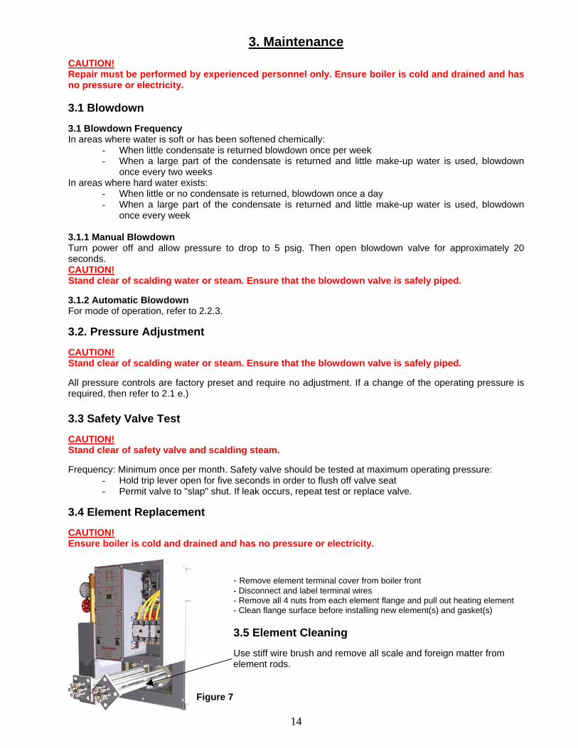
3.4 Element Replacement CAUTION! Ensure boiler is cold and drained and has no pressure or electricity.
- Remove element terminal cover from boiler front - Disconnect and label terminal wires - Remove all 4 nuts from each element flange and pull out heating element - Clean flange surface before installing new element(s) and gasket(s) 3.5 Element Cleaning Use stiff wire brush and remove all scale and foreign matter from element rods. Figure 7
15
3.6 Gauge Glass Replacement Frequency: Minimum once per year.
CAUTION! Ensure boiler is cold, drained and has no pressure or electricity. Be careful not to break glass.
- Close gauge glass valves (top and bottom) - Open petcock on bottom fixture of drain glass - Loosen nuts at top and bottom of glass - Slide glass up, pull out on bottom of glass and remove - Install glass by reversing above procedure
Always install new rubber washers. 3.7 Fuse Replacement
CAUTION! Do not insert the fuse in live circuits that will cause an arc that would cause a burr on the fuse cap, which will prevent good contact with the clips.
- If the insides of the clips and/or fuse caps are not bright and clean, brighten them with emery cloth.
- If the fuse can be easily inserted into the spring clips or can be easily rotated after it is inserted, there is not sufficient contact pressure. Take the fuse out and draw the clips together.
- If the clips have lost their spring, they should be replaced or clip clamps should be used. #1 for 0-30 amp/250 volt; #2 for 35-60 amp/250 volt Even if clamps are used be sure that the insides of clips are bright & clean.
3.8 Feed Water Pump Replacement
CAUTION! Ensure boiler is cold, drained and has no pressure or electricity.
When replacing the feed water pump, proceed as follows: - Unplug the power cord of the pump that needs to be replaced, disconnect pump ports from
solenoid valve and boiler water feed line, remove pump from pump plate. - Install new pump - Turn on ‘POWER”-switch on the boiler controller. Observe water level in gauge glass and ensure
that pump fills boiler to nominal water level. - Wait until boiler reaches the set operating steam pressure. - Test the setting of the pump pressure switch by Either: Caution: Before discharging steam, ensure that the boiler steam valve is properly piped! Open the boiler steam valve, discharge steam and wait until the “REFILLING”-light on the boiler controller turns on. The pump must turn on as soon as the “REFILLING”-light on the boiler controller is on.
Or: Caution: Before opening blowdown valve, ensure that it is properly piped! Open slowly the boiler blowdown valve and drain boiler water until the “REFILLING”-light on the boiler controller turns on. The pump must turn on as soon as the “REFILLING”-light on the boiler controller is on.
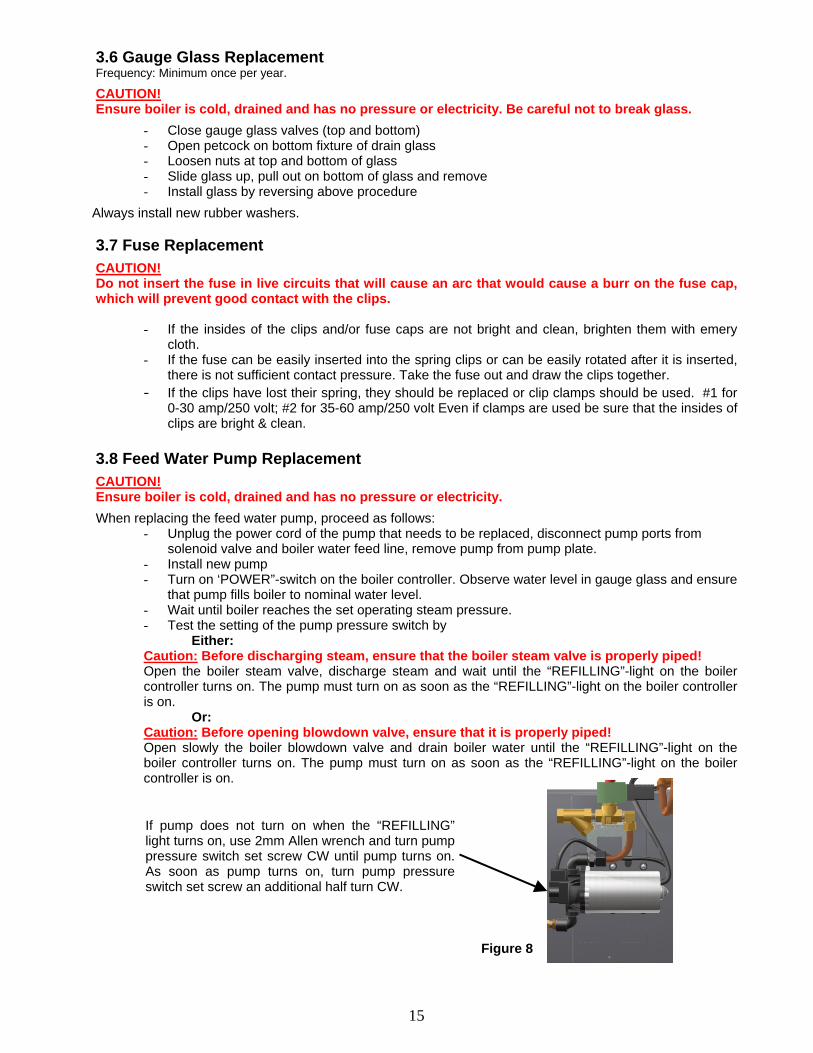
If pump does not turn on when the “REFILLING”light turns on, use 2mm Allen wrench and turn pumppressure switch set screw CW until pump turns on.As soon as pump turns on, turn pump pressureswitch set screw an additional half turn CW.
Figure 8

16
4. Trouble Shooting
Boiler Status
Quick Fix
POWER switch on boiler controller turned on, but no lights lit on the front panel of the boiler controller
- Check circuit breaker or fuse of the wall outlet where the boiler control voltage circuit is hooked up to. If the circuit breaker is tripped or the fuse blown, check whether other appliances are plugged into outlets that are fed by the same circuit breaker/fuse. If that is the case, then plug those other appliances into outlets that are protected by other circuit breakers or fuses.
LOW WATER alarm light on boiler controller panel lit:
- Press the LOW WATER reset button - Check Water Level. Water level must be visible in gauge
glass. - Ensure that the boiler is filled with Tap water and not distilled
or de-mineralized water. - Check the probe wires for continuity
HIGH PRESSURE alarm light on boiler controller panel lit:
- Press the HIGH PRESSURE reset switch - If the pressure gauge indicates steam pressure above the
preset value, reduce pressure and press the HIGH PRESSURE reset switch again.
Unit won’t build up pressure when POWER switch is on, boiler filled to nominal water level with water and HEATING light on the boiler controller is lit.
- Voltage Test: Read voltage across each element. If no voltage reading, check the voltage before and after the element contactor. If no voltage before the contactor, check fuses in fused disconnect switch. If no voltage reading after the contactor and contactor pulled in, replace contactor. If voltage reading after the contactor, go to Amperage Test.
- Amperage Test: Read amperage on each element wire. If no amperage reading on one or more element wires, replace heating elements.
Pump and/or solenoid valve energized, but no water enters the boiler
- Check water inlet strainer - Check whether the water feed shutoff valve is open
Boiler overfills or floods - Check water feed solenoid valve for sticking - Check the probe wires to the boiler controller for continuity - Check feed water. Boiler won’t operate with distilled or de-
mineralized water
Fuse blown - Short circuit or overload has occurred. Before replacing fuse, locate the short circuit or overload.
- Poor contact between fuse and fuse clips can cause fuse to blow. If surface that makes contact with the fuse clips is discolored, fuse has been making poor contact with the clips. Installing a larger fuse will not help. Replace the fuse holder.
Contactor(s) don’t pull in - Ensure that the contactor coil is receiving proper voltage - If contactor pulls in but chatters, clean magnetic core of
contactor - Further problems would indicate mechanical difficulties within
the contactor. - Complete contactor replacement is usually the least expensive
solution
“REFILLING” light on the boiler controller is lit, but feed water pump not energized
- Check for proper contact of the pump power cord to the receptacle
- Check for proper setting of the pump pressure switch. (Refer to chapter 3.8)
.
If trouble shooting did not resolve problem, please contact our service technicians at: Phone: 540-662-3811
Email: [email protected] LIVECHAT www.reimersinc.com
17
Instruction Supplement 1
Condensate Return System
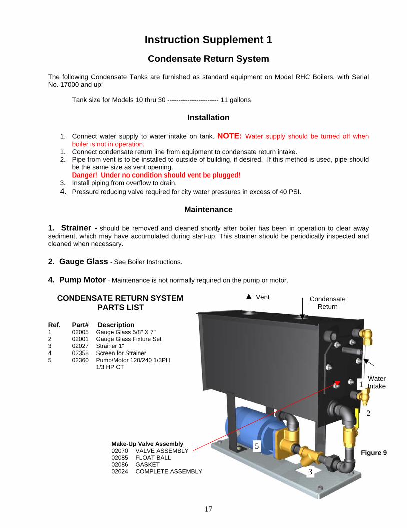
The following Condensate Tanks are furnished as standard equipment on Model RHC Boilers, with Serial No. 17000 and up: Tank size for Models 10 thru 30 ----------------------- 11 gallons
Installation
1. Connect water supply to water intake on tank. NOTE: Water supply should be turned off when
boiler is not in operation. 1. Connect condensate return line from equipment to condensate return intake. 2. Pipe from vent is to be installed to outside of building, if desired. If this method is used, pipe should
be the same size as vent opening. Danger! Under no condition should vent be plugged! 3. Install piping from overflow to drain. 4. Pressure reducing valve required for city water pressures in excess of 40 PSI.
Maintenance
1. Strainer - should be removed and cleaned shortly after boiler has been in operation to clear away sediment, which may have accumulated during start-up. This strainer should be periodically inspected and cleaned when necessary. 2. Gauge Glass - See Boiler Instructions. 4. Pump Motor - Maintenance is not normally required on the pump or motor. CONDENSATE RETURN SYSTEM PARTS LIST
Ref. Part# Description 1 02005 Gauge Glass 5/8" X 7" 2 02001 Gauge Glass Fixture Set 3 02027 Strainer 1" 4 02358 Screen for Strainer 5 02360 Pump/Motor 120/240 1/3PH 1/3 HP CT
CondensateReturn
Vent
Water Intake
Make-Up Valve Assembly 02070 VALVE ASSEMBLY 02085 FLOAT BALL 02086 GASKET 02024 COMPLETE ASSEMBLY 3
2
1
5Figure 9
18
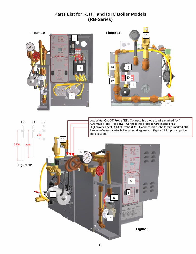
Parts List for R, RH and RHC Boiler Models (RB-Series)
1
1
2
3
9
10
1112
13
14
16 Figure 10
4
5
6
7
8
15
17
Low Water Cut-Off Probe (E3): Connect this probe to wire marked “14” Automatic Refill Probe (E1): Connect this probe to wire marked “13” High Water Level Cut-Off Probe (E2): Connect this probe to wire marked “10” Please refer also to the boiler wiring diagram and Figure 12 for proper probe identification.
Figure 12
E3 E1 E2
Figure 11
Figure 13

19
Ref. No. Wiring Diagram
Ref.
Part No. Description
1 K1, (K2) 02530 02531 02539 02540
Contactor 50A Res. 120V AC Coil Contactor 50A Res. 240V AC Coil Contactor 75A Res. 120V AC Coil Contactor 75A Res. 240V AC Coil
2 HR1, (HR2) 02685 04164 04277 02686 04165 04253 04153 04166 04666 02281
Element 9kW, 208V, 3Ph Element 10kW, 208V, 3Ph Element 15kW, 208V, 3Ph Element 9kW, 240V, 3Ph Element 10kW, 240V, 3Ph Element 15kW, 240V, 3Ph Element 9kW, 480V, 3Ph Element 10kW, 480V, 3Ph Element 15kW, 480V, 3Ph Gasket Element
3 F1 02655 02125 02140
Fuse 5A, 250V Fuse 15A, 250V Fuse Block 30A, 250V 1Pole
Not shown F2 03431 01520
Fuse Miniature 5A, 250V Fuse Block Miniature 250V 1Pole
4 B1 04178 03774
Pump with Cord 120V AC Pump 240V AC
5 SOL1 04761 02584
Solenoid Valve 3/8” NPT 120V AC/DIN-Connector Solenoid Valve 3/8” NPT 240V AC
6 A1/A2 20838 Boiler Controller 04316-EBC-LED-STM(1) 7 S3 04163
04162 Pressure Control Operating 100psi Pressure Control Operating 15psi
8 S4 04296 04162
Pressure Control High Limit 100psi Pressure Control High Limit 15psi
9 02396 Water Gauge Set 10 04569 Gauge Glass 5/8” OD x 4.125” 11 02006 Gauge Rubber Washer 12 02490 Valve Ball ½” NPT 13 03346 Valve Ball ½” NPT w/Latch 14 02370 Valve Check Ball Cone ½” NPT 15 02011
02011 Valve Globe 3/8” NPT Valve Globe
16 02637 02010
Valve Safety ½” NPT Valve Safety ¾” NPT
17 04661 02451
Pressure Gauge 2.0” ¼” NPT, 0-160psi Pressure Gauge 2.5” ¼” NPT, 0-30psi
20
REIMERS ELECTRA STEAM, INC. 4407 MARTINSBURG PIKE
CLEAR BROOK, VA 22624-0037 PHONE 540-662-3811 OR FAX 540-665-8101
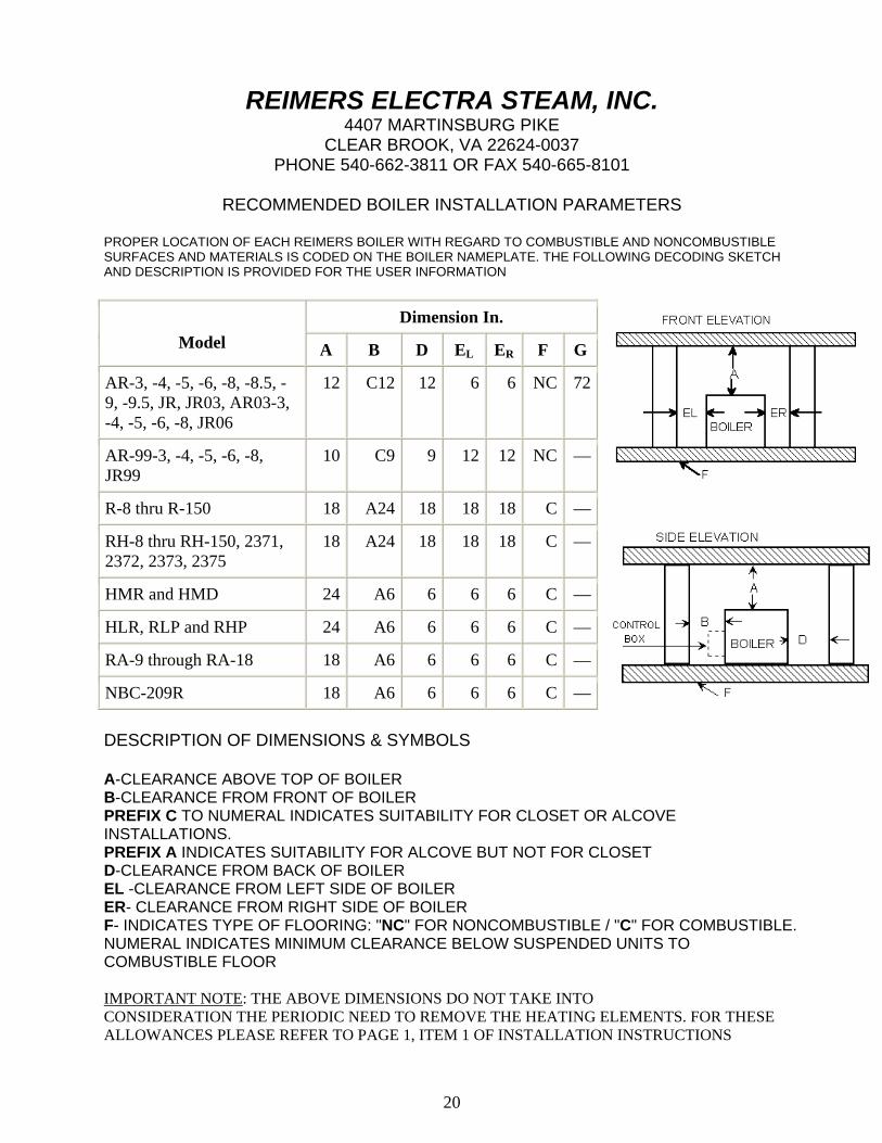
RECOMMENDED BOILER INSTALLATION PARAMETERS
PROPER LOCATION OF EACH REIMERS BOILER WITH REGARD TO COMBUSTIBLE AND NONCOMBUSTIBLE SURFACES AND MATERIALS IS CODED ON THE BOILER NAMEPLATE. THE FOLLOWING DECODING SKETCH AND DESCRIPTION IS PROVIDED FOR THE USER INFORMATION
Dimension In.
Model A B D EL ER F G
AR-3, -4, -5, -6, -8, -8.5, -9, -9.5, JR, JR03, AR03-3, -4, -5, -6, -8, JR06
12 C12 12 6 6 NC 72
AR-99-3, -4, -5, -6, -8, JR99
10 C9 9 12 12 NC —
R-8 thru R-150 18 A24 18 18 18 C —
RH-8 thru RH-150, 2371, 2372, 2373, 2375
18 A24 18 18 18 C —
HMR and HMD 24 A6 6 6 6 C —
HLR, RLP and RHP 24 A6 6 6 6 C —
RA-9 through RA-18 18 A6 6 6 6 C —
NBC-209R 18 A6 6 6 6 C — DESCRIPTION OF DIMENSIONS & SYMBOLS A-CLEARANCE ABOVE TOP OF BOILER B-CLEARANCE FROM FRONT OF BOILER PREFIX C TO NUMERAL INDICATES SUITABILITY FOR CLOSET OR ALCOVE INSTALLATIONS. PREFIX A INDICATES SUITABILITY FOR ALCOVE BUT NOT FOR CLOSET D-CLEARANCE FROM BACK OF BOILER EL -CLEARANCE FROM LEFT SIDE OF BOILER ER- CLEARANCE FROM RIGHT SIDE OF BOILER F- INDICATES TYPE OF FLOORING: "NC" FOR NONCOMBUSTIBLE / "C" FOR COMBUSTIBLE. NUMERAL INDICATES MINIMUM CLEARANCE BELOW SUSPENDED UNITS TO COMBUSTIBLE FLOOR IMPORTANT NOTE: THE ABOVE DIMENSIONS DO NOT TAKE INTO CONSIDERATION THE PERIODIC NEED TO REMOVE THE HEATING ELEMENTS. FOR THESE ALLOWANCES PLEASE REFER TO PAGE 1, ITEM 1 OF INSTALLATION INSTRUCTIONS