Embed Size (px)
Citation preview
ENGLISHDate: 05-2015Document number: 82331-2© 2015 Raymarine UK Limited
Release 14
MFD New features
LightHouse Release 14 — New Features


ContentsChapter 1 Important information........................ 5Trademark and patents notice .................................... 5................................................................................ 5
Chapter 2 New features (EN) .............................. 72.1 Product handbooks .............................................. 82.2 Laylines............................................................... 112.3 Building a route using racemark IDs ...................... 122.4 Race Startline and Race Timer ............................. 132.5 Polar tables ......................................................... 142.6 Automatic route generation ................................... 152.7 Language selection .............................................. 202.8 Compatible Fusion units ....................................... 212.9 Dual channel ping modes ..................................... 222.10 Intensity............................................................. 222.11 Surface filter....................................................... 23
3

4 LightHouse Release 14 — New Features

Chapter 1: Important information
Trademark and patents noticeRaymarine, Tacktick, Clear Pulse, Truzoom, HSB,SeaTalk, SeaTalkhs, SeaTalkng, Micronet, Raytech,Gear Up, Marine Shield, Seahawk, Autohelm,Automagic, and Visionality are registered orclaimed trademarks of Raymarine Belgium.FLIR, DownVision, SideVision, Dragonfly,Instalert, Infrared Everywhere, and The World’sSixth Sense are registered or claimed trademarksof FLIR Systems, Inc.All other trademarks, trade names, or companynames referenced herein are used for identificationonly and are the property of their respective owners.This product is protected by patents, design patents,patents pending, or design patents pending.Copyright ©2015 Raymarine UK Ltd. All rightsreserved.
Important information 5

6 LightHouse Release 14 — New Features

Chapter 2: New features (EN)
Chapter contents• 2.1 Product handbooks on page 8• 2.2 Laylines on page 11• 2.3 Building a route using racemark IDs on page 12• 2.4 Race Startline and Race Timer on page 13• 2.5 Polar tables on page 14• 2.6 Automatic route generation on page 15• 2.7 Language selection on page 20• 2.8 Compatible Fusion units on page 21• 2.9 Dual channel ping modes on page 22• 2.10 Intensity on page 22• 2.11 Surface filter on page 23
New features (EN) 7

2.1 Product handbooksThe latest versions of all English and translated handbooksare available to download in PDF format from the websitewww.raymarine.com.Please check the website to ensure you have the latesthandbooks.
8 LightHouse Release 14 — New Features
Software changesThe tables in this section describe the main changes that have been made since the last release of theproduct software. Use the links / references provided to find more information about each change.• Applicable software version: LightHouse II — Release 14.xx• Applicable products: a65 / a65 WiFi / a67 / a67 WiFi / a68 / a68 WiFi / a75 / a75 WiFi / a77 / a77 WiFi /a78 / a78 WiFi / a95 / a97 / a98 / a125 / a127 / a128 / e7 / e7D / c95 / c97 / c125 / c127 / e95 / e97 / e125/ e127 / e165 / eS75 / eS77 / eS78 / eS97 / eS98 / eS127 / eS128 / gS95 / gS125 / gS165 / gS195.
New features (EN) 9
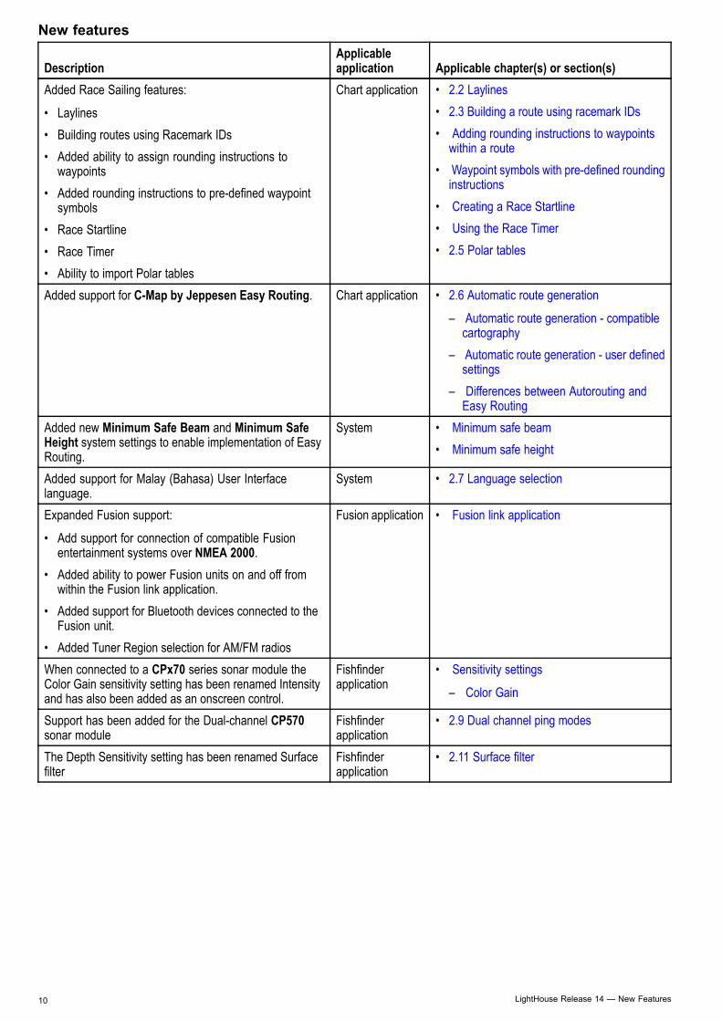
New features
DescriptionApplicableapplication Applicable chapter(s) or section(s)
Added Race Sailing features:
• Laylines• Building routes using Racemark IDs• Added ability to assign rounding instructions to
waypoints• Added rounding instructions to pre-defined waypoint
symbols• Race Startline• Race Timer• Ability to import Polar tables
Chart application • 2.2 Laylines• 2.3 Building a route using racemark IDs• Adding rounding instructions to waypoints
within a route• Waypoint symbols with pre-defined rounding
instructions• Creating a Race Startline• Using the Race Timer• 2.5 Polar tables
Added support for C-Map by Jeppesen Easy Routing. Chart application • 2.6 Automatic route generation
– Automatic route generation - compatiblecartography
– Automatic route generation - user definedsettings
– Differences between Autorouting andEasy Routing
Added new Minimum Safe Beam and Minimum SafeHeight system settings to enable implementation of EasyRouting.
System • Minimum safe beam• Minimum safe height
Added support for Malay (Bahasa) User Interfacelanguage.
System • 2.7 Language selection
Expanded Fusion support:
• Add support for connection of compatible Fusionentertainment systems over NMEA 2000.
• Added ability to power Fusion units on and off fromwithin the Fusion link application.
• Added support for Bluetooth devices connected to theFusion unit.
• Added Tuner Region selection for AM/FM radios
Fusion application • Fusion link application
When connected to a CPx70 series sonar module theColor Gain sensitivity setting has been renamed Intensityand has also been added as an onscreen control.
Fishfinderapplication
• Sensitivity settings
– Color Gain
Support has been added for the Dual-channel CP570sonar module
Fishfinderapplication
• 2.9 Dual channel ping modes
The Depth Sensitivity setting has been renamed Surfacefilter
Fishfinderapplication
• 2.11 Surface filter
10 LightHouse Release 14 — New Features
2.2 LaylinesLaylines are used in sailing to show how far thevessel must sail on the current tack in order to makethe target waypoint after tacking, given presentwind conditions. Laylines are based on the TrueWind Direction (TWD) and fixed or polar upwindand downwind sailing angles. Sailing along laylinesmaximizes your Velocity Made Good (VMG) towindward.Laylines are displayed under the following conditions:• The Boat Type setting is set to one of the availablesailing vessels
• The vessel is under active navigation towards awaypoint
• The layline path to the destination point is lessthan 150 nm
• The angle between port and starboard laylines isless than 170°
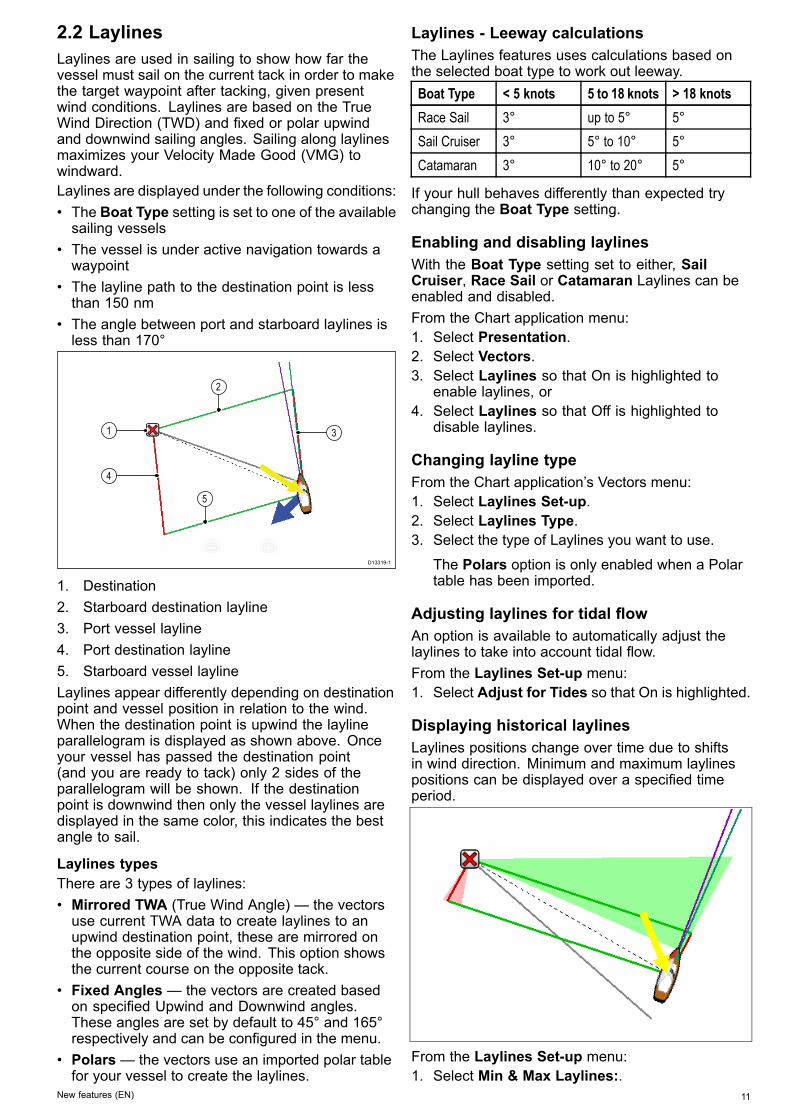
D13319-1
1
4
3
2
5
1. Destination2. Starboard destination layline3. Port vessel layline4. Port destination layline5. Starboard vessel laylineLaylines appear differently depending on destinationpoint and vessel position in relation to the wind.When the destination point is upwind the laylineparallelogram is displayed as shown above. Onceyour vessel has passed the destination point(and you are ready to tack) only 2 sides of theparallelogram will be shown. If the destinationpoint is downwind then only the vessel laylines aredisplayed in the same color, this indicates the bestangle to sail.
Laylines typesThere are 3 types of laylines:• Mirrored TWA (True Wind Angle) — the vectorsuse current TWA data to create laylines to anupwind destination point, these are mirrored onthe opposite side of the wind. This option showsthe current course on the opposite tack.
• Fixed Angles — the vectors are created basedon specified Upwind and Downwind angles.These angles are set by default to 45° and 165°respectively and can be configured in the menu.
• Polars— the vectors use an imported polar tablefor your vessel to create the laylines.
Laylines - Leeway calculationsThe Laylines features uses calculations based onthe selected boat type to work out leeway.Boat Type < 5 knots 5 to 18 knots > 18 knotsRace Sail 3° up to 5° 5°Sail Cruiser 3° 5° to 10° 5°Catamaran 3° 10° to 20° 5°
If your hull behaves differently than expected trychanging the Boat Type setting.
Enabling and disabling laylinesWith the Boat Type setting set to either, SailCruiser, Race Sail or Catamaran Laylines can beenabled and disabled.From the Chart application menu:1. Select Presentation.2. Select Vectors.3. Select Laylines so that On is highlighted to
enable laylines, or4. Select Laylines so that Off is highlighted to
disable laylines.
Changing layline typeFrom the Chart application’s Vectors menu:1. Select Laylines Set-up.2. Select Laylines Type.3. Select the type of Laylines you want to use.
The Polars option is only enabled when a Polartable has been imported.
Adjusting laylines for tidal flowAn option is available to automatically adjust thelaylines to take into account tidal flow.From the Laylines Set-up menu:1. Select Adjust for Tides so that On is highlighted.
Displaying historical laylinesLaylines positions change over time due to shiftsin wind direction. Minimum and maximum laylinespositions can be displayed over a specified timeperiod.
From the Laylines Set-up menu:1. Select Min & Max Laylines:.
New features (EN) 11

2. Select the time period that you want the historicaldata to cover.
Historical Laylines can be reset at any time byselecting Reset Min & Max Laylines from theLaylines Set-up menu.
2.3 Building a route using racemarkIDsYou can build a route quickly by entering a list ofracemark IDs. Each Racemark ID must be uniqueand must have been entered into the comments fieldof the relevant waypoints.Racemark IDs must:• only use alpha numeric characters• not include any spaces• be separated from any other information in thefield using a space.
From the Chart application menu:1. Select My Data.2. Select Routes.3. Select Build using racemark IDs.
An instructional pop-up is displayed, unless youhave previously selected Don’t show again.
4. If the pop-up is displayed, select Continue.The onscreen keyboard is displayed.
5. Enter the relevant racemark IDs, in order, usinga comma to separate each ID that you want toinclude in your route.e.g. entering A2,HK,M5,S,4 and selectingCREATE ROUTE will search for and create aroute using the 5 waypoints with matching IDs.
Once created you can select individual waypointsand apply rounding instructions.
Adding rounding instructions to waypointswithin a routeRounding instructions can be added to waypointswithin a route to indicate the direction the vesselshould take around the waypoint.To use the Rounding feature the Boat Type settingmust be set to a sailing vessel.
12 LightHouse Release 14 — New Features
With the Route plan displayed:1. Select the Waypoint that you want to add a
rounding direction to.2. Select Rounding Direction.3. Select a rounding option:
• None• Leave to Port• Leave to Starboard
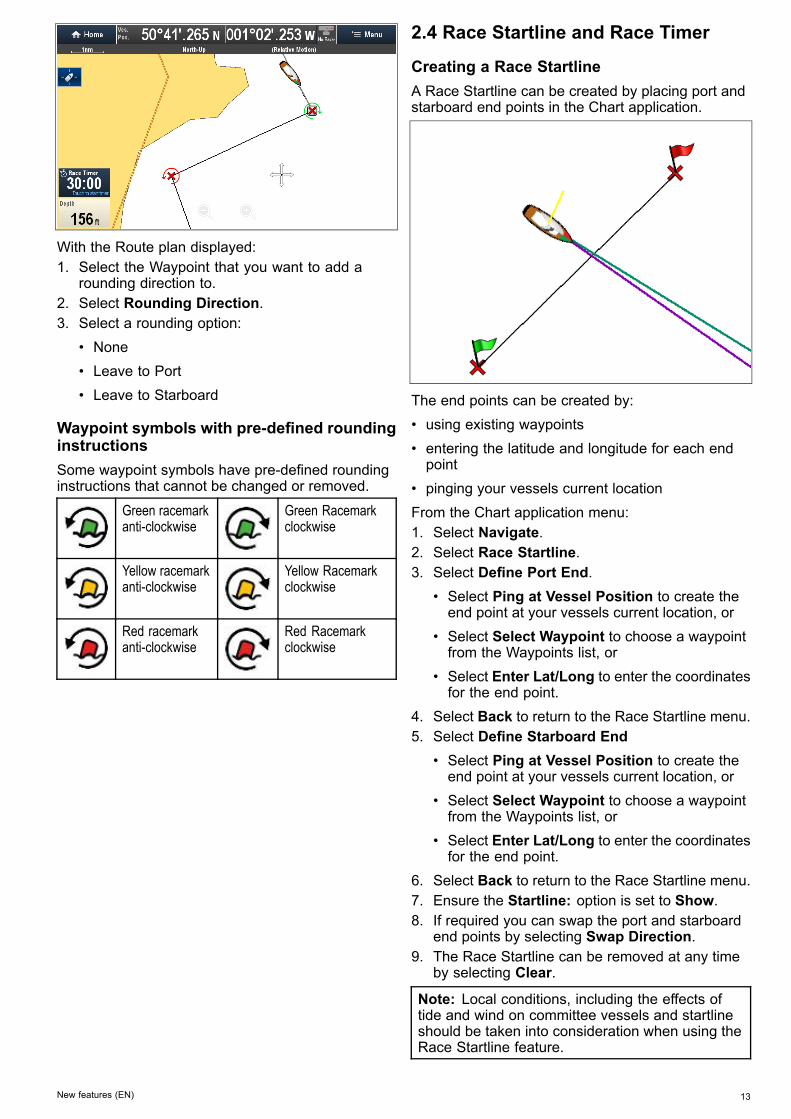
Waypoint symbols with pre-defined roundinginstructionsSome waypoint symbols have pre-defined roundinginstructions that cannot be changed or removed.
Green racemarkanti-clockwise
Green Racemarkclockwise
Yellow racemarkanti-clockwise
Yellow Racemarkclockwise
Red racemarkanti-clockwise
Red Racemarkclockwise
2.4 Race Startline and Race Timer
Creating a Race StartlineA Race Startline can be created by placing port andstarboard end points in the Chart application.
The end points can be created by:• using existing waypoints• entering the latitude and longitude for each endpoint
• pinging your vessels current locationFrom the Chart application menu:1. Select Navigate.2. Select Race Startline.3. Select Define Port End.
• Select Ping at Vessel Position to create theend point at your vessels current location, or
• Select Select Waypoint to choose a waypointfrom the Waypoints list, or
• Select Enter Lat/Long to enter the coordinatesfor the end point.
4. Select Back to return to the Race Startline menu.5. Select Define Starboard End
• Select Ping at Vessel Position to create theend point at your vessels current location, or
• Select Select Waypoint to choose a waypointfrom the Waypoints list, or
• Select Enter Lat/Long to enter the coordinatesfor the end point.
6. Select Back to return to the Race Startline menu.7. Ensure the Startline: option is set to Show.8. If required you can swap the port and starboard
end points by selecting Swap Direction.9. The Race Startline can be removed at any time
by selecting Clear.
Note: Local conditions, including the effects oftide and wind on committee vessels and startlineshould be taken into consideration when using theRace Startline feature.
New features (EN) 13
Using the Race TimerA count down Race Timer is available in the Chartapplication. Once the Race Timer reaches zero it willchange color and start to count up, after 10 secondsthe Race Timer will automatically be hidden from thescreen but continue to count up.From the Chart application’s Navigate menu:1. Select Race Timer.2. Select Show Race Timer in Chart.3. Select Countdown From:.4. Set the timer to the required value.
The Race Timer can be set from 1 minute to 30minutes.
5. Select Back to return to the Race Timer menu.6. Select Start to start the Race Timer countdown.
• You can synchronize the Race Timer countdown by selecting Skip to Next Minute.
• You can stop and reset the Race Timer byselecting Stop & Reset.
7. With the Race Timer count down stopped, youcan hide the timer by selecting Hide Race Timer
8. With the Race Timer hidden you can display itagain by selecting Show Race Timer in Chartfrom the menu.
Using the Race Timer — TouchscreencontrolsThe Race Timer can be controlled by interacting withthe onscreen Race Timer.
From the Chart application, with the Race Timerdisplayed:1. Touch the Race Timer to start the countdown.2. With the timer running you can select the Race
Timer to synchronize.3. Touch and hold the Race Timer to stop and reset
the countdown.
2.5 Polar tablesPolar coordinate tables for your vessel can beimported in .csv format. The layout of the .csv filemust adhere to the layout detailed below.Spreadsheet programs such as Microsoft Excel canbe used to .csv files.The following table layout constraints apply:
Column 1• The first cell is ignored• Column 1 must contain the relevant TWA angles• A minimum of 3 TWA angles are required
Rows• The first cell is ignored• Row 1 must contain the relevant TWS values inknots
• A minimum of 3 TWS values are required
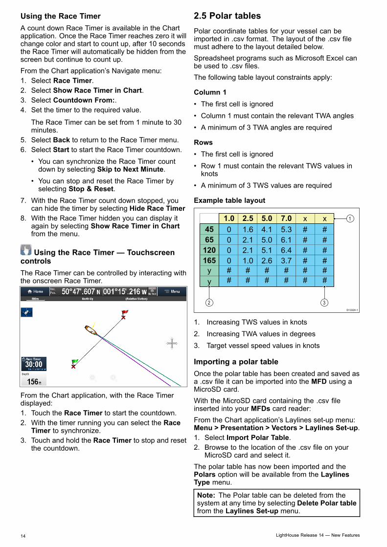
Example table layout
1.0
4565
120165
2.5 5.0 7.0 xx
############
####
####
y
0 1.62.1
4.15.0
5.36.1
2.1 5.1 6.41.0 2.6 3.7
000
y
D13324-1
2 3
1
1. Increasing TWS values in knots2. Increasing TWA values in degrees3. Target vessel speed values in knots
Importing a polar tableOnce the polar table has been created and saved asa .csv file it can be imported into the MFD using aMicroSD card.With the MicroSD card containing the .csv fileinserted into your MFDs card reader:From the Chart application’s Laylines set-up menu:Menu > Presentation > Vectors > Laylines Set-up.1. Select Import Polar Table.2. Browse to the location of the .csv file on your
MicroSD card and select it.The polar table has now been imported and thePolars option will be available from the LaylinesType menu.
Note: The Polar table can be deleted from thesystem at any time by selecting Delete Polar tablefrom the Laylines Set-up menu.
14 LightHouse Release 14 — New Features

2.6 Automatic route generationAutomatic route generation can be used toautomatically create the shortest route between 2waypoints. Automatic route generation can be usedwhen creating new routes or when adding a routeleg to an existing route.
The generated route is based on the data availableon compatible cartography compared with userdefined settings. Waypoints automatically generatedwill be restricted from entering areas that do notadhere to the user defined settings.
Important: The following restrictions apply:• Automatic route generation can only be usedwhen generating routes within the area coveredby your compatible cartography.
• Automatic route generation can be usedbetween waypoints less than 100 nm apart.
• Automatic route generation always usesthe cartography’s minimum depth readingwhen calculating routes. Please refer to theDifferences between Autorouting and EasyRouting section for further details.
• Automatic route generation will fail if thegenerated route will exceed the maximumwaypoint or route capacity of the MFD.
• Automatic route generation will also fail ifinsufficient cartographic data is available.
Automatic route generation - compatiblecartographyAutomatic route generation requires compatibleNavionics® or C-MAP by Jeppesen cartography.The Navionics® Autorouting feature is available onthe following cartography:• Navionics® Updates• Navionics® PlatinumTM
• Navionics® PlatinumTM+The C-MAP by Jeppesen Easy Routing feature isavailable on the following cartography:• C-MAP 4D MAX• C-MAP 4D MAX+
Automatic route generation - user definedsettingsUser defined settings must be set before usingautomatic route generation. The settings used forroute generation are dependent on cartographyvendor.
User settingNavionics®Autorouting
C-MAP byJeppesenEasy Routing
Minimum SafeDepthMinimum SafeBeamMinimum SafeHeight
Refer to Initial set up procedures for details onsetting the required user defined settings.
New features (EN) 15

Differences between Autorouting and EasyRoutingThere are important differences between the wayNavionics® and Jeppesen® handle automatic routegeneration.
Navionics®Autorouting
C-MAP byJeppesenEasy Routing
Tidal height —Depth clearance
Autoroutingavoids shallowareas based onthe user definedMinimum SafeDepth settingplus an additionalNavionicssafety margin.Autoroutingassumes thelowest tide level,normally LowestAstronomical Tide(LAT). The tide canbe lower than LATdue to atmosphericeffects such ashigh air pressure,wind direction, etc.
Easy Routingassumes that therewill be some tide.The user mustapply their ownsafety margin asappropriate tocurrent conditions.Route legs thatcross areasshallower thanthe user definedMinimum SafeDepth settingare marked withhazard waypointsymbols, it iscritical that theselegs are checkedto ensure thatthere is sufficienttide to avoid thehazard.
Beam / Heightconstraints
Autorouting doesnot use the userdefined MinimumSafe Beam orMinimum SafeHeight settings togenerate routes.Objects with beam/ height constraintsare marked withhazard waypointsymbols, it iscritical that theselegs are checkedto ensure thatthere is sufficientclearance to avoidthe hazard.
Easy Routinguses the userdefined MinimumSafe Beam andMinimum SafeHeight settingsto determineif sufficientclearance isavailable. Theuser mustapply there ownsafety margin asappropriate tocurrent conditions.The Height datummust be checked,as it could beMean High WaterSprings (MHWS)or HighestAstronomical Tide(HAT). In bothcases the tide canbe higher thanthe datum dueto atmosphericeffects such ashigh air pressure,wind direction, etc.
Caution: Easy Routing - DredgedareasThe Jeppesen Easy Routing feature willignore some hazards in dredged areas.Easy Routing is intended for passageplanning between harbors rather thanwithin a harbor.
Warning: Automatic routegenerationRoutes created using automatic routegeneration rely on data taken fromcompatible electronic cartography anduser defined settings. As both of thesevalues are subjective the generatedroute MUST be carefully checked andif necessary edited BEFORE starting tofollow the route in the Chart application.
Warning: Traffic separationAutomatic route generation featuresdo not adhere to the Traffic SeparationSchemes identified in Rule 10 of theInternational Regulations for PreventingCollisions at Sea 1972 as amended.Raymarine® therefore recommendsthat you do NOT use Automatic routegeneration to create any part of a routewhich will cross traffic lanes or passnear to traffic separation lines. In thesesituations Automatic route generationMUST be switched Off and the routeor route leg MUST be built manually,ensuring compliance to the rules laid outin the above regulations.
Building a route using automatic routegenerationAutomatic route generation can be used to create anentire route or can be activated at any time whenbuilding a new route.From the Chart application:1. Select Build Route from the chart context menu
or the Navigate menu.The Build Route menu is displayed.
2. Select Autorouting / Easy Routing so that Onis selected.
Autorouting / Easy Routing can be switchedOn and Off at any time during route building.
16 LightHouse Release 14 — New Features

3. Select the position on the Chart where you wantthe route or route leg to start.
4. Select the position on the Chart where you wantthe route or route leg to end.
The system will try to automatically calculate theshortest safe route between the 2 points.
If the automatic route generation completessuccessfully the calculated route is displayed.
Waypoints within the route that were calculatedusing automatic route generation are assignedthe Marker waypoint symbol.
5. Subsequent route legs can be added by selectingthe next desired location on the Chart.
6. When your route is complete select Finish Build.The Finish Route Build warning is displayed.
7. Select Exit to complete the route and close theBuild Route menu.
8. Select Follow to immediately start following thegenerated route.
Important: Do not rely on automatic routegeneration alone to guarantee that the route is safeto navigate. Review the suggested route carefullyand if necessary edit the route before following.
9. Select Edit to display the Route in the Route List
You can further customize the route from theroute list. Reviewing the route list is not anadequate method of checking a route, pleaserefer to Reviewing an automatically generatedroute for details on how to check a route.
Once finished, routes generated automatically willbehave the same as any other route.
Important: Automatic route generation will NOTbe used when moving waypoints within routes,extra care should be taken to ensure that the routeleg and any moved waypoints are safe to navigate.
Reviewing an automatically generated routeBefore you start to follow any route you shouldreview each waypoint and route leg to ensure it isappropriate to follow.
New features (EN) 17

With the completed route displayed:1. Range in on the route to identify areas of caution.
Areas of caution should be identified by the useof the Caution waypoint symbol before and afterthe cautionary area.
2. Range in further to review the area around andbetween the caution symbols.In the example below the route passes close to acharted buoy.
3. Once the reason for the caution has beenidentified you can manipulate the route by movingthe caution waypoints so that the caution areais avoided.
Note: Automatic route generation will NOT beused when moving waypoints within routes, extracare should be taken to ensure that the route legand any moved waypoints are safe to navigate.
4. Scroll over the entire route to identify any otherareas that might be of concern, that have notbeen highlighted with Caution symbols.
Important: Due to variations in detail and accuracyof cartography at different zoom levels, automaticroute generation may not highlight all areas ofconcern within a route. It is therefor essential thatthe entire route is checked before following.
Example route legIn the example below the automatic routegeneration has not identified the pile as a hazard.
D13331-1
Warning: Minimum Safe Depth,Beam and HeightDepending on cartography vendor, theminimum safe settings are used duringautomatic route generation, they are usedto restrict created routes from enteringwater that is not suitable for the vessel.Data is taken from compatible cartography.Minimum safe settings are user definedcalculations. As both of these factorsare outside of Raymarine’s control;Raymarine will not be held liable forany damage, physical or otherwise,resulting from the use of the automaticroute generation feature or the MinimumSafe Depth, Minimum Safe Beam orMinimum Safe Height settings.
Minimum safe vessel depthAs part of the Initial startup wizard the MinimumSafe Depth value can be set.Minimum Safe Depth can be established by addingtogether:• Maximum Vessel Draft (i.e. the distance from thewaterline to the lowest point of a vessel’s keel.)
• Safety Margin (an adequate clearance below thekeel to allow for draft variation and changes inwater or bottom conditions.)
i.e.: Minimum Safe Depth = Maximum Vessel Draft+ Safety Margin.
18 LightHouse Release 14 — New Features
D13159-1
2 4
1
3
1. Waterline2. Maximum Vessel Draft3. Safety Margin4. Minimum Safe DepthImportant: The information below is providedfor guidance only and is not exhaustive. Someinfluencing factors can be unique to certain vesselsand / or areas of water and may not be listedbelow. You should ensure you account for ALLfactors that apply to your current situation whenmaking calculations.
Some of the factors that can influence how much avessel draws are shown below:• Vessel displacement (weight)— A vessel’s draftwill increase when it is fully laden when comparedwith its unladen displacement.
• Water type — A vessel’s draft will increase byapproximately 2% to 3% in fresh water comparedto seawater.
Some of the factors that should be taken into accountwhen calculating a Safety Margin are:• Vessel maneuvering characteristics — Avessel’s draft increases due to squat, trim, roll,pitch and heave.
• Chart accuracy — The electronic chart depthmay not be accurate or the true depth may havechanged since the last survey.
• Weather conditions — High air pressure, andprevailing wind strength and direction can affectwave height.
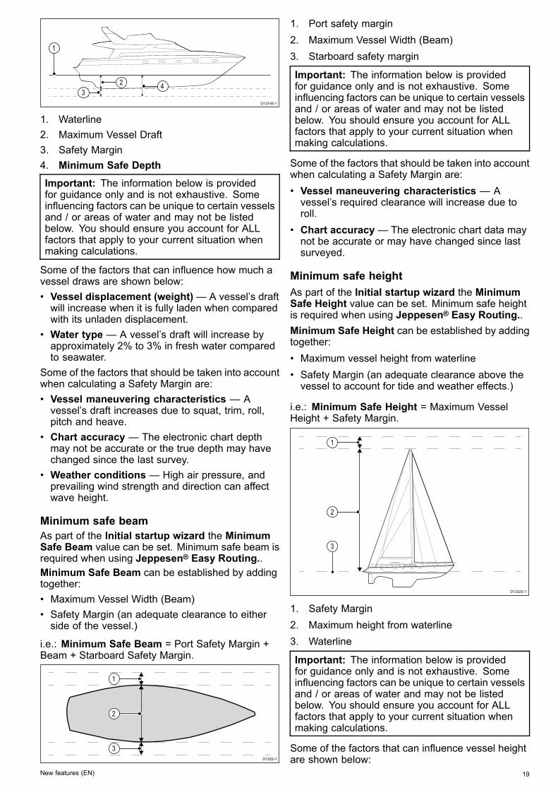
Minimum safe beamAs part of the Initial startup wizard the MinimumSafe Beam value can be set. Minimum safe beam isrequired when using Jeppesen® Easy Routing..Minimum Safe Beam can be established by addingtogether:• Maximum Vessel Width (Beam)• Safety Margin (an adequate clearance to eitherside of the vessel.)
i.e.: Minimum Safe Beam = Port Safety Margin +Beam + Starboard Safety Margin.
D1322-1
2
1
3
1. Port safety margin2. Maximum Vessel Width (Beam)3. Starboard safety margin
Important: The information below is providedfor guidance only and is not exhaustive. Someinfluencing factors can be unique to certain vesselsand / or areas of water and may not be listedbelow. You should ensure you account for ALLfactors that apply to your current situation whenmaking calculations.
Some of the factors that should be taken into accountwhen calculating a Safety Margin are:• Vessel maneuvering characteristics — Avessel’s required clearance will increase due toroll.
• Chart accuracy— The electronic chart data maynot be accurate or may have changed since lastsurveyed.
Minimum safe heightAs part of the Initial startup wizard the MinimumSafe Height value can be set. Minimum safe heightis required when using Jeppesen® Easy Routing..Minimum Safe Height can be established by addingtogether:• Maximum vessel height from waterline• Safety Margin (an adequate clearance above thevessel to account for tide and weather effects.)
i.e.: Minimum Safe Height = Maximum VesselHeight + Safety Margin.
1
2
3
D13323-1
1. Safety Margin2. Maximum height from waterline3. Waterline
Important: The information below is providedfor guidance only and is not exhaustive. Someinfluencing factors can be unique to certain vesselsand / or areas of water and may not be listedbelow. You should ensure you account for ALLfactors that apply to your current situation whenmaking calculations.
Some of the factors that can influence vessel heightare shown below:
New features (EN) 19

• Vessel displacement (weight) — A vessel’sheight (from the waterline) will decrease whenit is fully laden when compared with its unladendisplacement.
• Water type — A vessel’s height will decrease byapproximately 2% to 3% in fresh water comparedto seawater.
Some of the factors that should be taken into accountwhen calculating a Safety Margin are:• Vessel maneuvering characteristics — Avessel’s height changes due to squat, trim, roll,pitch and heave.
• Chart accuracy— The electronic chart data maynot be accurate or may have changed since thelast survey.
• Weather conditions — Low air pressure, andprevailing wind strength and direction can affectwater level.
Setting the vessel Minimum Safe Depth,Beam and HeightFrom the Homescreen:1. Select Customize.2. Select Boat Details.3. Select Min. Safe Depth, Min. Safe Beam or
Min. Safe Height.4. Enter your calculated minimum safe settings.
2.7 Language selectionThe system can operate in the following languages:
English (US) English (UK) ArabicBulgarian Chinese —
SimplifiedChinese —Traditional
Croatian Czech DanishDutch Finnish FrenchGerman Greek HebrewHungarian Icelandic ItalianJapanese Korean Malay (Bahasa)Norwegian Polish Portuguese
(Brazilian)Russian Slovenian SpanishSwedish Turkish
With the Homescreen displayed:1. Select Customize.2. Select Language.3. Select your language from the list of languages.Language is part of the Shared Preferences scheme.Once a new language is selected the User interfacelanguage will change on all MFDs networked usingSeaTalkhs or SeaTalkng and, if the language issupported any instrument displays networked usingSeaTalkng .
20 LightHouse Release 14 — New Features

2.8 Compatible Fusion unitsThe table below details the Fusion entertainmentsystems that are compatible with Raymarine®LightHouseTM powered MFDs.
Fusion unitNMEA 2000connection
SeaTalkhsconnection
650 Series
700 Series
750 Series
RA205 Series
Powering off an NMEA 2000 Fusion unitFrom the Fusion link application:1. Select the Menu icon.2. Select Power off.
The Fusion unit will power off.The Fusion link application will display the unitselection page.
Powering on an NMEA 2000 Fusion unitWith the unit selection page displayed.1. Select the unit that you want to power up.
Menu optionsThe menu options available are dependent on themedia source connected.
Menu option Media sources DescriptionBrowse Music • iPod
• USBEnables browsingof music storedon the selecteddevice.
Repeat • iPod• USB
• Off• Folder —
Repeats allsongs in thecurrent folder
Shuffle • iPod• USB
Switches trackshuffle on and off.
Tone Controls • All devices Enablesadjustment ofthe following tonecontrols:
• Bass• Middle• Treble
Tuner region • All devices • USA• Europe• Japan• Australasia
Menu option Media sources DescriptionUpdate • All devices Initiate software
update of Fusionunit.
Power Off • All devices Powers off theFusion unit anddisplays the unitselection page.Only availablewhen connectedover NMEA 2000.
Select Fusionsystem
• All devices Enables you toselect the Fusionentertainmentsystem you wantto control.
Preset • AM / FM Radio• VHF Radio
Enables selectionand saving ofchannels aspresets.
Scan • VHF Radio Enables scanningof saved channels.
New features (EN) 21

2.9 Dual channel ping modesThe CP570 sonar module features 2 CHIRP sonarchannels that can transmit and receive independentlyof each other. Ping modes are available that balancethe ping rate Vs interference between the 2 channels.Ping modes:• Auto— The system selects the best mode basedon your chosen range settings.
• Independent pings — Maximum ping rate, butgreater chance of interference.
• Simultaneous pings — Reduced ping rate,based on the deepest range setting, but reducedchance of interference.
Note: Ping modes will only be available whenthe sonar module is connected to a 2 channeltransducer.
Selecting a ping modeFrom the Fishfinder application menu:1. Select Set-up.2. Select Sounder Set-up.3. Select Dual-Channel Ping Modes.
The ping mode selection page is displayed.
4. Select the required ping mode.
2.10 IntensityWhen connected to a CPx70 series sonar modulethe Intensity control is available. Sonar modulesuse different colors to determine the strength of anecho. You can adjust the color intensity manuallybetween 0% and 100% or set it to automatic. WhenIntensity is set to automatic the setting can be offsetby +/- 50%.The Intensity control sets the lower limit for thestrongest echo color. All echoes with a signalstrength above this value are displayed in thestrongest color. Those with a weaker value aredivided equally between the remaining colors.• Setting a low value produces a wide band for theweakest color, but a small signal band for theother colors.
• Setting a high value gives a wide band for thestrongest color, but a small signal band for theother colors.
Onscreen Intensity controlThe onscreen Intensity control is available whenconnected to a CPx70 series sonar module.Selecting the onscreen control enables you to adjustthe setting as required.
The Auto Intensity can beoffset by +/-50%When in manual mode theslider bar control
Adjusting the IntensityTo adjust the Intensity control on a CPx70 seriessonar module follow the steps below.From the Fishfinder application:1. Select Menu.2. Select Sensitivity settings.3. Select Intensity.
The slider bar control is displayed.4. Adjust the control to the required value.5. Select Back to confirm setting and close slider
bar, or6. Select Auto to enable automatic Intensity control.
Setting auto Intensity offsetWhen connected to a CPx70 series sonar modulethe Auto Intensity can be offset by +/–50%.From the Sensitivity Settings menu:1. Select Intensity.2. Ensure Auto is selected.3. Adjust the slider control to the required value.The scrolling image will now track the automaticsetting by the offset value specified.
22 LightHouse Release 14 — New Features

2.11 Surface filterThe Surface filter setting is available whenconnected to a CPx70 series sonar module. Thecontrol reduces the amount of noise / clutterdisplayed near the surface by varying the gainthroughout the water column.
0% 100%
The Surface filter can be set to automatic or can beadjusted manually. In manual:• a low value decreases the depth to which the filteris applied and produces stronger targets / moreclutter near the surface.
• a high value increases the depth to which the filteris applied and produces weaker targets / lessclutter near the surface.
Adjusting the Surface filterAdjusting the Surface filter settings can improve thesonar image.From the Sensitivity Settings menu:1. Select Surface Filter.2. Adjust the slider control to the required value, or3. Select Auto to allow the system to automatically
adjust the Surface Filter for current conditions.
New features (EN) 23

24 LightHouse Release 14 — New Features


www.raymarine.com