Embed Size (px)
Citation preview
> REPLACE THIS LINE WITH YOUR PAPER IDENTIFICATION NUMBER (DOUBLE-CLICK HERE TO EDIT) <
1
Abstract—A novel planar Yagi-Uda antenna is presented in
this letter. The proposed antenna uses electrically small
resonators as radiating elements that behave as short electric
dipoles. Its radiation pattern, gain, front-to-back ratio (FBR) and
efficiency are maintained close to that of a Yagi-Uda antenna of
stacked half-wavelength dipoles. However, its physical
dimensions are considerably reduced. The choice of the resonant
particle and its radiation properties, along with the antenna
structure, are discussed. Simulated results show a good
impedance matching (29 dB) at the working frequency of
5.5 GHz for a 15-elements antenna, as well as a high gain
(11.5 dBi). These characteristics are experimentally validated and
compared with that of others Yagi-Uda designs from the
literature.
Index Terms—Electrically small resonators, end-fire array,
front-to-back ratio, gain, planar Yagi-Uda antenna.
I. INTRODUCTION
HE Yagi-Uda antenna [1], [2] has been widely used as
an end-fire antenna in the last years for TV and amateur
radio applications. The classical Yagi-Uda antenna consists of
an array of parallel electric dipoles, where only one element
needs to be fed and the remaining parasitic elements
contribute to build a directional radiation pattern. To optimize
the gain and front-to-back ratio (FBR), the lengths and spacing
between elements must be properly adjusted [3], [4]. In order
to reduce the bulkiness, Yagi-Uda antennas have been
implemented in planar substrates, which provide low profile,
light weight and mechanical support, as well as compatibility
with printed circuitry. On the other hand, feeding the active
element can be troublesome due to the presence of the
parasitic radiators, although a truncated microstrip ground
plane as reflecting element can avoid the use of a reflector
dipole [5]. Planar Yagi-Uda antennas can be also configured
into arrays to improve the directive gain [6] or the fractional
bandwidth [7].
Microstrip Yagi-Uda array antennas based on rectangular
patches, first studied by Huang in 1989 [8], avoid the feeding
This work has been supported by MINECO-Spain (project TEC2013-
40600-R COM-SEN-RFID), by Generalitat de Catalunya (project 2014SGR-
157) and by FEDER funds. Ferran Martín has been awarded with an ICREA
Academia Award.
The authors are with GEMMA/CIMITEC, Departament d’Enginyeria
Electrònica, Universitat Autònoma de Barcelona, 08193 Bellaterra, Spain (e-
mail: [email protected]).
issue and also have the advantages of low profile, simple
topology and high gain. However, this solution provided low
FBR and was not able to radiate completely end-fire, due to
the radiation properties of the patch elements. Successive
works focused on improving such limitations achieved high
FBR [9], [10] and end-fire radiation [11], where vertical
polarization was also obtained due to the excitation of
magnetic moments orthogonally to the antenna surface.
Although the length of Yagi-Uda arrays can be tailored by
modifying the number of directors, which controls the
directivity, their width is typically set by the length of the
radiating elements, which is usually close to a half-
wavelength. A classic approach to reduce the width consists of
using one-wavelength loop elements [12], [13], whose
diameter is roughly λ0/3 (being λ0 the free-space wavelength at
the working frequency). However, this solution involves a
significant increase in the antenna cross-section, and it can not
be applied in planar topology.
In this letter, a new planar Yagi-Uda antenna design with
significantly reduced width in comparison with conventional
designs is presented. The main idea consists in replacing the
array elements with electrically small resonators, such as the
split-ring resonator (SRR), typically employed in metamaterial
devices [14], [15]. Such resonators, along with several derived
structures, have also been employed to enhance the
functionality of antennas [16], [17], including Yagi-Uda arrays
as follows. In [18], meander SRRs etched in the active
element reduced the width to λ0/3.3, though the gain was
significantly reduced. In [19], multiband functionality was
obtained by means of square spiral resonator (SSR) loading,
and recently, a dual-band design with opposite beam
directions was achieved by adding SRRs to the passive
element [20]. Nevertheless, the use of such resonators as
radiators in Yagi-Uda antennas has not been reported to date.
The radiation properties of the SRR antenna at the first
(fundamental) and second resonance have been recently
analyzed in [21] and [22], respectively. The analysis
highlighted that the SRR operated at its second resonance
behaves similarly to a half-wave dipole antenna, in terms of
input impedance and radiation resistance, yet its lateral
dimensions are reduced by almost a factor two. This fact
allows a significant reduction of the antenna width, while
maintaining similar radiation properties (mainly the gain and
the FBR) of the original configuration. As a proof of concept,
Planar Yagi-Uda Antenna Array based on Split Ring
Resonators (SRRs)
Pau Aguilà, Student Member, IEEE, Simone Zuffanelli, Member, IEEE, Gerard Zamora, Member,
IEEE, Ferran Paredes, Member, IEEE, Ferran Martín, Fellow, IEEE, and Jordi Bonache, Member, IEEE
T

> REPLACE THIS LINE WITH YOUR PAPER IDENTIFICATION NUMBER (DOUBLE-CLICK HERE TO EDIT) <
2
-
- -
-
---
-
--
x
y
cd
r i0i0
z
Fig. 1. Layout and charge distributions of the Split Ring Resonator at the
second resonance.
a 15-elements planar Yagi-Uda array based on SRRs working
at f0 = 5.5 GHz for wireless local area network (WLAN)
applications is implemented in this letter.
The work is organized as follows. Section II is focused on
the analysis and design of the antenna. To validate the
simulated results, a prototype is fabricated and its
characteristics are measured and compared with the state-of-
the-art in Section III. Finally, the main conclusions are
highlighted in Section IV.
II. PROPOSED STRUCTURE
A. Principle of Operation
The proposed antenna is an arrangement of electrically
small resonators, in this work the SRR, whose topology is
illustrated in Fig. 1. As already mentioned, the SRR operating
at the second resonance shows high radiation efficiency and an
input resistance close to that of a half-wavelength dipole,
while reducing the lateral dimensions by roughly a factor of
two [22]. At the second resonance, the SRR mainly exhibits an
electric dipole moment in the y-direction, since the currents in
the internal and external rings flow in opposite directions.
Such a current configuration also leads to a significant
cancellation of the axial magnetic dipole moment generated by
the individual rings. Although the far-field contribution of the
residual magnetic dipole moment generates a cross-polar
component in most directions, that contribution becomes
entirely co-polar along the xz-plane, where the fields radiated
by both moments are parallel. As a result, the polarization
along the main beam of the proposed antenna (x-direction) is
expected to be linear.
To take advantage of the abovementioned behavior, a Yagi-
Uda antenna has been designed, where the canonical half-
wavelength dipoles implementing the active and parasitic
elements (directors and reflector) have been replaced by
SRRs. In order to achieve a very directional radiation pattern
with high gain in the end-fire direction, a great number of
directors has been used. As suggested by conventional Yagi-
Uda antenna theory [23], the directors were set to be slightly
smaller than the active element, whereas the reflector was set
to be slightly larger. Also, the separation between the reflector
and the active element was set to be somewhat smaller than
the spacing between directors.
B. Design Process
The layout of the proposed SRR-based Yagi-Uda antenna
REFLECTORDIRECTORS
ACTIVE
x
y
z
VIALp Wp
VIA
BOTTOM SIDETOP SIDE
Fig. 2. (a) Illustration of the planar SRR Yagi-Uda array, (b) Feeding network
of the active element
TABLE I
GEOMETRICAL PARAMETERS OF THE SRRS
REFLECTOR DRIVEN DIRECTORS
c (mm) 0.72 0.70 0.67
d (mm) 0.36 0.35 0.34
r (mm) 5.11 4.96 4.76
consists of 15 elements, as shown in Fig. 2(a). An ArlonCU
233LX substrate slab is used, with relative permittivity
εr = 2.43, dielectric loss tanδ = 0.0022 and thickness
h = 0.49 mm.
Let us now proceed to design the active element. As stated
in [22], the SRR mean radius r is determined to be r = λ0/11 in
order to adjust its radiation resistance (which is close to the
input impedance due to the low dielectric and ohmic losses) to
50 Ω at resonance. Thus, the mean radius was fixed to
r = 4.96 mm at f0 = 5.5 GHz. The second step consists of
obtaining the strip width c. The radiation efficiency of the
SRR can be expressed as a function of the metal conductivity
σ, the mean radius r and the strip width c. Therefore, to ensure
an efficiency above 90% by using copper, the strip was set to
c = 0.7 mm. The last step consisted of adjusting the second
resonance of the SRR at the operating frequency f0 by tailoring
the distance d, which controls the coupling between rings. As
a result, a distance of d = 0.35 mm was chosen. The ring cut
width, which does not significantly affect the SRR behavior,
was set to 1.3 mm.
The parasitic radiators are designed to optimize the antenna
end-fire gain and FBR while keeping the input impedance
close to 50 Ω. By means of a parametric analysis, their size
and separation were swept around their initial values. As a
result, the director was chosen to be 4% smaller than the
exciter (while preserving its aspect ratio) and the reflector was
found to be 3% larger. The spacing between all directors was
set to 17.5 mm center-to-center (0.32λ0). Finally, the distance
between the active element and the reflector, which has a
strong influence on the antenna input impedance [23], was
swept to maintain good impedance matching to 50 Ω,
(b)
(a)

> REPLACE THIS LINE WITH YOUR PAPER IDENTIFICATION NUMBER (DOUBLE-CLICK HERE TO EDIT) <
3
Fig. 3. Simulated and measured power reflection coefficient of the proposed
antenna.
Fig. 4. Normalized simulated and measured radiation pattern evaluated at
5.72 GHz in the (a) H-plane (xz) and (b) E-plane (xy).
resulting in a value of 15 mm center-to-center (0.28λ0). Table I
summarizes all the geometrical parameters for the different
elements.
An antipodal excitation based on a paired strip transmission
line was used to feed the exciter at the center of the external
ring [Fig. 2(b)]. By this means, the use of a balun to feed the
antenna is avoided [24], [25]. The strip located in the back
side is connected to the lower half of the SRR trough a
metallic via. The electrical length of the line was fixed to λ0/2
in order to maintain the input impedance equal to that of the
antenna, which, as mentioned above provides good impedance
matching. Its dimensions were found to be Lp = 18.2 mm and
Wp = 0.7 mm, respectively.
III. SIMULATED AND EXPERIMENTAL RESULTS
The layout of the antenna described in Section II has been
simulated by means of CST-Microwave Studio. Its power
Fig. 5. Illustration of the fabricated SRR Yagi-Uda antenna prototype.
Fig. 6. Measured maximum gain and FBR within the –10 dB bandwidth.
reflection coefficient is depicted in Fig. 3, showing a good
impedance matching level (almost –30 dB) around f0, with a
−10 dB bandwidth of 179 MHz. The simulated radiation
pattern is shown in Fig. 4. The antenna exhibits a maximum
gain of 11.5 dBi or, equivalently, 9.35 dBd in the end-fire
direction (θ = 90º, ϕ = 0º) with a radiation efficiency of 84%.
The FBR and the 3-dB beam-width are about 14 dB and 32.5º,
respectively, for both planes, but the SLL (Sidelobe Level) is
equal to −6.1 dB in the H-plane and −10.4 dB in the E-plane.
To validate the simulated results, the proposed antenna has
been manufactured (Fig. 5) by means of a printed circuit board
(PCB) milling machine LPKF-H100. A 50-Ω SMA connector
soldered on the input port is used to feed the array. The power
reflection coefficient of the proposed antenna has been
measured by means of an Agilent N5221A network analyzer.
The results (Fig. 3) show an excellent impedance matching
and a −10 dB bandwidth of 191 MHz, which are in
concordance with simulations. However, a frequency shift of
165 MHz is produced, as a result of fabrication tolerances.
The experimental radiation pattern of the antenna was
obtained with an Agilent N5221A network analyzer using the
gain transfer method [26]. The Antenna Under Test (AUT)
and a reference antenna (DE0518 broadband horn antenna)
were connected to the two ports of the network analyzer and
the S21 was measured (taking the reference plane at the input of
each antenna). The separation between both antennas was set
to 8 m, which is higher than the inner boundary of the far field
(Fraunhofer) region [23] of the reference antenna (7.4 m) and
the AUT (2.3 m). The power gain of our antenna was
calculated then from the measured S21 using the Friis
transmission formula.
The measured radiation pattern is plotted in Fig. 4, showing
minor variations with the simulated results due to the
scattering effects from the measurement setup. The maximum
gain, FBR and 3-dB beam-width are close to the simulated
values. However, the measured SLL is 3 dB below its
expected value in the H-plane and 3 dB higher in the E-plane.
As shown in Fig. 6, the FBR is more sensitive as a function of
frequency than the gain, but both parameters show smooth
5,00 5,25 5,50 5,75 6,00-30
-20
-10
0
S1
1 (
dB
)
Frequency (GHz)
Simulation
Measurement
-25
-20
-15
-10
-5
00
30
60
90
120
150
180
210
240
270
300
330
-25
-20
-15
-10
-5
0
Simulation
Measurement
-25
-20
-15
-10
-5
0
0
30
60
90
120
150
180
210
240
270
300
330
-25
-20
-15
-10
-5
0
Simulation
Measurement
0
3
6
9
12
15
FB
R (d
B)
Ga
in (
dB
)
10
15
20
25
5,60 5,64 5,68 5,72 5,76 5,80
Frequency (GHz)
(b)
(a)
> REPLACE THIS LINE WITH YOUR PAPER IDENTIFICATION NUMBER (DOUBLE-CLICK HERE TO EDIT) <
4
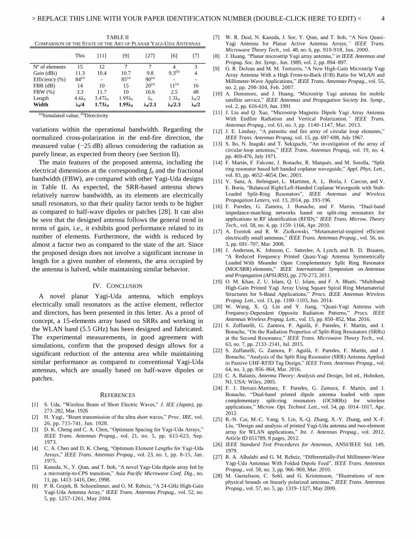
TABLE II
COMPARISON OF THE STATE OF THE ART OF PLANAR YAGI-UDA ANTENNAS
This [11] [9] [27] [6] [7]
Nº of elements 15 12 7 7 4 3 Gain (dBi) 11.3 10.4 10.7 9.8 9.3(b) 4
Efficiency (%) 84(a) - 85(a) 90(a) - -
FBR (dB) 14 10 15 20(a) 11(a) 16 FBW (%) 3.3 11.7 10 16.6 2.5 48
Length 4.6λ0 3.47λ0 1.95λ0 λ0 1.3λ0 λ0/2
Width λ0/4 1.73λ0 1.95λ0 λ0/2.1 λ0/2.3 λ0/2
(a)Simulated value; (b)Directivity
variations within the operational bandwidth. Regarding the
normalized cross-polarization in the end-fire direction, the
measured value (−25 dB) allows considering the radiation as
purely linear, as expected from theory (see Section II).
The main features of the proposed antenna, including the
electrical dimensions at the corresponding f0 and the fractional
bandwidth (FBW), are compared with other Yagi-Uda designs
in Table II. As expected, the SRR-based antenna shows
relatively narrow bandwidth, as its elements are electrically
small resonators, so that their quality factor tends to be higher
as compared to half-wave dipoles or patches [28]. It can also
be seen that the designed antenna follows the general trend in
terms of gain, i.e., it exhibits good performance related to its
number of elements. Furthermore, the width is reduced by
almost a factor two as compared to the state of the art. Since
the proposed design does not involve a significant increase in
length for a given number of elements, the area occupied by
the antenna is halved, while maintaining similar behavior.
IV. CONCLUSION
A novel planar Yagi-Uda antenna, which employs
electrically small resonators as the active element, reflector
and directors, has been presented in this letter. As a proof of
concept, a 15-elements array based on SRRs and working in
the WLAN band (5.5 GHz) has been designed and fabricated.
The experimental measurements, in good agreement with
simulations, confirm that the proposed design allows for a
significant reduction of the antenna area while maintaining
similar performance as compared to conventional Yagi-Uda
antennas, which are usually based on half-wave dipoles or
patches.
REFERENCES
[1] S. Uda, “Wireless Beam of Short Electric Waves,” J. IEE (Japan), pp. 273–282, Mar. 1926
[2] H. Yagi, “Beam transmission of the ultra short waves,” Proc. IRE, vol.
26, pp. 715-741, Jun. 1928. [3] D. K. Cheng and C. A. Chen, “Optimum Spacing for Yagi-Uda Arrays,”
IEEE Trans. Antennas Propag., vol. 21, no. 5, pp. 615-623, Sep.
1973. [4] C. A. Chen and D. K. Cheng, “Optimum Element Lengths for Yagi-Uda
Arrays,” IEEE Trans. Antennas Propag., vol. 23, no. 1, pp. 8-15, Jan.
1975. [5] Kaneda, N., Y. Qian, and T. Itoh, “A novel Yagi-Uda dipole array fed by
a microstrip-to-CPS transition,” Asia Pacific Microwave Conf. Dig., no.
11, pp. 1413–1416, Dec. 1998.
[6] P. R. Grajek, B. Schoenlinner, and G. M. Rebeiz, “A 24-GHz High-Gain
Yagi-Uda Antenna Array,” IEEE Trans. Antennas Propag., vol. 52, no.
5, pp. 1257-1261, May 2004.
[7] W. R. Deal, N. Kaneda, J. Sor, Y. Qian, and T. Itoh, “A New Quasi-
Yagi Antenna for Planar Active Antenna Arrays,” IEEE Trans. Microwave Theory Tech., vol. 48, no. 6, pp. 910-918, Jun. 2000.
[8] J. Huang, “Planar microstrip Yagi array antenna,” in IEEE Antennas and
Propag. Soc. Int. Symp., Jun. 1989, vol. 2, pp. 894–897. [9] G. R. DeJean and M. M. Tentzeris, “A New High-Gain Microstrip Yagi
Array Antenna With a High Front-to-Back (F/B) Ratio for WLAN and
Millimeter-Wave Applications,” IEEE Trans. Antennas Propag., vol. 55, no. 2, pp. 298-304, Feb. 2007.
[10] A. Densmore, and J. Huang, “Microstrip Yagi antenna for mobile
satellite service,” IEEE Antennas and Propagation Society Int. Symp., vol. 2, pp. 616-619, Jun. 1991
[11] J. Liu and Q. Xue, “Microstrip Magnetic Dipole Yagi Array Antenna
With Endfire Radiation and Vertical Polarization,” IEEE Trans. Antennas Propag., vol. 61, no. 3, pp. 1140-1147, Mar. 2013.
[12] J. E. Lindsay, “A parasitic end fire array of circular loop elements,”
IEEE Trans. Antennas Propag, vol. 15, pp. 697-698, July 1967. [13] S. Ito, N. Inagaki and T. Sekiguchi, “An investigation of the array of
circular-loop antennas,” IEEE Trans. Antennas Propag, vol. 19, no. 4,
pp. 469-476, July 1971.
[14] F. Martín, F. Falcone, J. Bonache, R. Marqués, and M. Sorolla, “Split
ring resonator based left handed coplanar waveguide,” Appl. Phys. Lett.,
vol. 83, pp. 4652–4654, Dec. 2003. [15] V. Sanz, A. Belenguer, L. Martinez, A. L. Boria, J. Cascon, and V.
E. Boria, “Balanced Right/Left-Handed Coplanar Waveguide with Stub-
Loaded Split-Ring Resonators”, IEEE Antennas and Wireless Propagation Letters, vol. 13, 2014, pp. 193-196.
[16] F. Paredes, G. Zamora, J. Bonache, and F. Martin, “Dual-band impedance-matching networks based on split-ring resonators for
applications in RF identification (RFID),” IEEE Trans. Microw. Theory
Tech., vol. 58, no. 4, pp. 1159–1166, Apr. 2010. [17] A. Erentok and R. W. Ziolkowski, “Metamaterial-inspired efficient
electrically small antennas,” IEEE Trans. Antennas Propag., vol. 56, no.
3, pp. 691–707, Mar. 2008. [18] J. Anderson, K. Johnson, C. Satterlee, A. Lynch, and B. D. Braaten,
“A Reduced Frequency Printed Quasi-Yagi Antenna Symmetrically
Loaded With Meander Open Complementary Split Ring Resonator
(MOCSRR) elements,” IEEE International Symposium on Antennas
and Propagation (APSURSI), pp. 270-273, 2011.
[19] O. M. Khan, Z. U. Islam, Q. U. Islam, and F. A. Bhatti, “Multiband High-Gain Printed Yagi Array Using Square Spiral Ring Metamaterial
Structures for S-Band Applications,” Procs. IEEE Antennas Wireless
Propag. Lett., vol. 13, pp. 1100–1103, Jun. 2014. [20] W. Wang, X. Q. Lin and Y. Jiang, “Quasi-Yagi Antenna with
Frequency-Dependent Opposite Radiation Patterns,” Procs. IEEE
Antennas Wireless Propag. Lett., vol. 15, pp. 850–852, Mar. 2016. [21] S. Zuffanelli, G. Zamora, P. Aguilà, F. Paredes, F. Martín, and J.
Bonache, “On the Radiation Properties of Split-Ring Resonators (SRRs)
at the Second Resonance,” IEEE Trans. Microwave Theory Tech., vol. 63, no. 7, pp. 2133–2141, Jul. 2015.
[22] S. Zuffanelli, G. Zamora, P. Aguilà, F. Paredes, F. Martín, and J.
Bonache, “Analysis of the Split Ring Resonator (SRR) Antenna Applied to Passive UHF-RFID Tag Design,” IEEE Trans. Antennas Propag., vol.
64, no. 3, pp. 856–864, Mar. 2016.
[23] C. A. Balanis, Antenna Theory: Analysis and Design, 3rd ed., Hoboken, NJ, USA: Wiley, 2005.
[24] F. J. Herraiz-Martinez, F. Paredes, G. Zamora, F. Martin, and J.
Bonache, “Dual-band printed dipole antenna loaded with open complementary split-ring resonators (OCSRRs) for wireless
applications,” Microw. Opt. Technol. Lett., vol. 54, pp. 1014–1017, Apr.
2012. [25] R.-N. Cai, M.-C. Yang, S. Lin, X.-Q. Zhang, X.-Y. Zhang, and X.-F.
Liu, “Design and analysis of printed Yagi-Uda antenna and two-element
array for WLAN applications,” Int. J. Antennas Propag., vol. 2012, Article ID 651789, 8 pages, 2012.
[26] IEEE Standard Test Procedures for Antennas, ANSI/IEEE Std. 149,
1979. [27] R. A. Alhalabi and G. M. Rebeiz, “Differentially-Fed Millimeter-Wave
Yagi-Uda Antennas With Folded Dipole Feed”, IEEE Trans. Antennas
Propag., vol. 58, no. 3, pp. 966–969, Mar. 2010. [28] M. Gustafsson, C. Sohl, and G. Kristensson, “Illustrations of new
physical bounds on linearly polarized antennas,” IEEE Trans. Antennas
Propag., vol. 57, no. 5, pp. 1319–1327, May 2009.


![Periodic Plasmonic Nanoantennas in a Piecewise …...Although the concept of nanoantenna has been around since 1985 [1], it is ... monopoles, dipoles and bowties to Yagi-Uda nanoantennas](https://img.dokumen.tips/doc/110x75/5f4f21a83bde496e35386ec9/periodic-plasmonic-nanoantennas-in-a-piecewise-although-the-concept-of-nanoantenna.jpg)