Embed Size (px)
Citation preview

ComforTrakTM Series Assembly Instructions
R
EP-960™ & EP-970™ Inversion Tables
Pour télécharger et imprimer les instructions de montage du dossier ComforTrak™ en français, rendezvous sur teeter-inversion.com
Para descargar e imprimir las instrucciones de montaje de ComforTrak™ en español, visite teeter-inversion.com
TEET
ER HANG UPS
W
ARRANTY
YEAR5FULL
* Inversion Table images may vary slightly from your model.
The EP-960 is shown here.
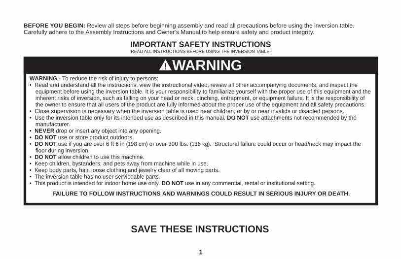
IMPORTANT SAFETY INSTRUCTIONSREAD ALL INSTRUCTIONS BEFORE USING THE INVERSION TABLE.
SAVE THESE INSTRUCTIONS
WARNING - To reduce the risk of injury to persons: • Read and understand all the instructions, view the instructional video, review all other accompanying documents, and inspect the
equipment before using the inversion table. It is your responsibility to familiarize yourself with the proper use of this equipment and the inherent risks of inversion, such as falling on your head or neck, pinching, entrapment, or equipment failure. It is the responsibility of the owner to ensure that all users of the product are fully informed about the proper use of the equipment and all safety precautions.
• Close supervision is necessary when the inversion table is used near children, or by or near invalids or disabled persons.• Use the inversion table only for its intended use as described in this manual. DO NOT use attachments not recommended by the
manufacturer.• NEVER drop or insert any object into any opening.• DO NOT use or store product outdoors.• DO NOT use if you are over 6 ft 6 in (198 cm) or over 300 lbs. (136 kg). Structural failure could occur or head/neck may impact the
floor during inversion.• DO NOT allow children to use this machine.• Keep children, bystanders, and pets away from machine while in use.• Keep body parts, hair, loose clothing and jewelry clear of all moving parts.• The inversion table has no user serviceable parts.• This product is intended for indoor home use only. DO NOT use in any commercial, rental or institutional setting.
FAILURE TO FOLLOW INSTRUCTIONS AND WARNINGS COULD RESULT IN SERIOUS INJURY OR DEATH.
BEFORE YOU BEGIN: Review all steps before beginning assembly and read all precautions before using the inversion table. Carefully adhere to the Assembly Instructions and Owner’s Manual to help ensure safety and product integrity.
1
WARNING!

IMPORTANT SAFETY INSTRUCTIONSREAD ALL INSTRUCTIONS BEFORE USING THE INVERSION TABLE.
SAVE THESE INSTRUCTIONS
FAILURE TO FOLLOW INSTRUCTIONS AND WARNINGS COULD RESULT IN SERIOUS INJURY OR DEATH.
BEFORE YOU BEGIN: Review all steps before beginning assembly and read all precautions before using the inversion table. Carefully adhere to the Assembly Instructions and Owner’s Manual to help ensure safety and product integrity.
• DO NOT use the equipment without a licensed physician’s approval and a review of the medical contraindications, as noted in the Owner’s Manual.
• Failure to assemble and/or use the equipment as directed may void the manufacturer’s warranty on this product and could result in injury or death.
• Choose a level surface for assembling and operating the table.• Follow each step in sequence. DO NOT skip ahead. • Make sure that all fasteners are secure.• ALWAYS test and inspect the table. Make sure the table rotates smoothly to inverted position and back.• ALWAYS replace defective components immediately and/or keep the equipment out of use until repair.
2
WARNING!

ITEMS FOR ASSEMBLY (Page 1 of 2)
3
E61100 F51008
E61301A E61300B HK1006
E61630
NX1620
ITEM NAME ITEM NUMBERStretch-and-GripTM Base Assembly A-Frame EZ-Angle Tether pre-assembled to A-Frame
ComforTrakTM Table Bed Assembly Upper Portion with pre-assembled Bed Frame Extension Lower Portion with pre-assembled Bed Frame Table Bed Assembly Hardware Kit Large Bolt (1), Small Bolts (2), Nuts (3)
Main Shaft with EZ-ReachTM Ankle Lock System Assembly
Main Shaft with Deluxe EZ-ReachTM Ankle Lock System Assembly
E61520 HK1007
TR1003
E61105
F51088 IA1149
ITEM NAME ITEM NUMBERHandle Assembly Stretch MaxTM Handles (2) Stretch MaxTM Handle Assembly Hardware Kit Allen Head Bolts (6), Bolts (2), Nuts (2), Washers (6)
Roller Hinge Assembly 3-Hole Roller Hinges with Traction Handles (2)
Optional Accessories Head Pillow
Tools Provided for Assembly 10/13mm Open-Ended Wrenches (2) 5mm Allen Wrench (1)

ITEMS FOR ASSEMBLY (Page 2 of 2) Items not shown to scale. Hardware drawings located on the insert inside each Hardware Kit.
4
Stretch-and-Grip Base Assemblywith pre-assembled Angle Tether
F51088
ComforTrak Table Bed Assemblyuse Table Bed Assembly Hardware Kit (HK1006)
Main Shaft with EZ-Reach Ankle Lock Systemfor use with EP-960 models only
Main Shaft with Deluxe EZ-Reach Ankle Lock System
for use with EP-970 models only
Stretch Max Handle Assemblyuse Stretch Max Handle Assembly Hardware Kit (HK1007)
Roller Hinge Assembly
Optional Accessories
Tools Provided for Assembly
IA1149
E61100
F51008
E61301A
E61520
TR1003
E61105
E61300B
NX1620
E61630

Head Pillow
Bed Frame Extension
ComforTrak™ Table Bed
Pivot Pins
Hinge Plates
Self-Locking Hooks
3-Hole Roller Hinges
Stretch Max™ Handles
Height-Selector Locking Pin
1
2
3
4
5
6
7
8
9
Spreader Arms
EZ-Angle Tether
Crossbar
A-Frame
Main Shaft
Ankle Lock System
Ankle Comfort Dial™
Stability Feet
UNDERSTANDING YOUR INVERSION TABLE
Identifying Parts and Components
* Inversion Table images may vary slightly from your model.
The EP-960 is shown here.
Before reading further, study the drawing below to familiarize yourself with the important components of your new Teeter Hang Ups® Inversion Table.
Located on back of table
bed.
10
11
12
13
14
15
16
17
23
910
8
1312 11
15
16
17
4
5
6
7
5
14
1

Important: Please review all labels and supporting materials before using your inversion table.
This drawing indicates the locations of the warning labels found on your product.
If a label is missing, illegible or is removed, contact Customer Service at the phone number or website found on the last page to request a complimentary replacement label.
Note: Image and labels below not shown at actual size.
WARNING / AVERTISSEMENTADVERTENCIA
!
E6-1740-M 1112-0Do not use Setting A for users over 220 lbs (100kgs).Ne pas utiliser le réglage A pour les utilisateurs plus 100 kgs (220 lbs).
No utilizar Configuración A para los usuarios de 100kg (220lbs). Replace label if damaged, illegible, or removed. / Remplacer l’etiquette si endommage
ou enleve. / Reemplace las etiquetassi se llegará dañar, se volvieran ilegibles o a perder. WARNING / AVERTISSEMENTADVERTENCIA
!
NX-1750-M 1112-2
TIPPING HAZARD: For upright storage, leave A-Frame open wide enough to remain stable, or secure to thewall to prevent tipping. In households with small children, the table should be stored flat on the floor, not upright. DANGER DE RENVERSEMENT: Pour un rangement en position verticale, laissez le cadre en A suffisamment ouvert pour qu'il reste stable, ou appuyez-le sur un mur pour éviter les chutes. Dans les foyers avec de jeunes
enfants, cette table devrait être rangée à plat sur le sol et non pas debout.PELIGRO DE DESLIZAMIENTO: Para guardar la tabla parada, deje la estructura A lo suficiente abierta paraque quede estable, o asegúrela a la pared para prevenir que se deslice y caiga. En casa con niños pequeños,
la tabla debe guardarse acostada sobre el piso, no parada. Replace label if damaged, illegible, or removed. / Remplacer l’etiquette si endommage
ou enleve. / Reemplace las etiquetassi se llegará dañar, se volvieran ilegibles o a perder.
WARNING / AVERTISSEMENTADVERTENCIA
!
IA-2007-M 1112-2Ankles must be properly secured before use. Les chevilles doivent etre convenablement a obtenu avant l’usage.Los tobillos deben estar propiamente asegurados antes de usarse.
Replace label if damaged, illegible, or removed. / Remplacer l’etiquette si endommageou enleve. / Reemplace las etiquetassi se llegará dañar, se volvieran ilegibles o a perder.
WARNING LABEL PLACEMENT DIAGRAM
6
Teeter, 9902 162nd St. Ct. E., Puyallup, WA 98375Teléfono: 800-847-0143 www.teeter-inversion.com
ADVERTENCIA!
EP-1737-S 0612-2
ADVERTENCIA - Para reducir el riesgo de lesiones personales o muerte • Lea y entienda todas las instrucciones antes de usar la tabla de inversión.
Es su responsabilidad familiarizarse con el uso adecuado del equipo y con los riesgos inherentes de la inversión, tales como caer de cabeza o en el cuello, pellizcarse, quedar atrapado o que el equipo falle.
• No permita que niños usen este equipo.• Mantenga niños, espectadores y mascotas lejos del equipo mientras este en uso.• Mantenga partes corporales, cabello, ropa holgada y joyería alejados de las partes móviles.• Capacidad de Altura/Peso: 4 pies 8 pulgadas, 6 pies 6 pulgadas
(142-198 cm); 300 libras (136 kg).• Este producto está diseñado solamente para uso casero en interiores.Reemplace las etiquetas y el manual del usuario si se llegará dañar,se volvieran ilegibles o a perder.
Teeter, 9902 162nd St. Ct. E., Puyallup, WA 98375Téléphone: 800-847-0143 www.teeter-inversion.com
AVERTISSEMENT!
EP-1737-F 0612-2
AVERTISSEMENT - Afin de réduire le risque de blessures ou la mort: • Lire et comprendre toutes les instructions avant d’utiliser la table d’inversion.
Vous êtes responsable de vous familiariser avec l’utilisation correcte de cet appareil et aux risques inhérents à l’inversion tels que le risque de tomber sur la tête ou sur le cou, les pincements,la possibilité de rester coincé, ou les risques de défaillances de l’appareil.
• NE PAS permettre aux enfants d’utiliser cet appareil.• Maintenir les enfants, les spectateurs et les animaux de compagnie éloignés
lors de l’utilisation de l’appareil.• Maintenir toutes les parties du corps, les cheveux, les vêtements amples et
les bijoux éloignés de toutes les pièces en mouvement.• Capacité de hauteur/poids: 1,42 m-1,98 m (4 ft 8 in – 6 ft 6 in); 136 kg (300 lbs)• Ce produit est pour l’usage domestique intérieur seulement.Remplacer L’etiquette Si Endommage Ou Enleve.
WARNING - To reduce the risk of personal injury or death:• Read and understand all the instructions before using the inversion table.
It is your responsibility to familiarize yourself with the proper use of the equipment and the inherent risks of inversion, such as falling on your head or neck, pinching, entrapment or equipment failure.
• Do not allow children to use the machine. • Keep children, bystanders, and pets away from the machine while in use. • Keep body parts, hair, loose clothing and jewelry clear of all moving parts. • Height/Weight capacity: 4 ft 8 in - 6 ft 6 in (142-198 cm); 300 lbs (136 kgs).• This product is for consumer, indoor household use only. Replace Labels and Owner’s Manual if Damaged, Illegible, or Removed.Teeter, 9902 162nd St. Ct. E., Puyallup, WA 98375Toll Free (Phone): 800-847-0143 Web: www.teeter-inversion.com
WARNING!
EP-1737 0911-3 * Inversion Table images may vary slightly from your model.
The EP-960 is shown here.

Unpack and Prepare Your Workspace
• If possible, set up the product at or near the space in which you intend to use it to avoid moving it later.
• Unpack all parts and support materials. Set aside packing materials and clear your work area.
• Locate the Hardware Kits, packaged with the manuals. They are labeled to correspond with the assembly process.
• The Assembly & Use DVD provides step-by-step instruction on how to assemble your product. You may find it helpful to follow along with the DVD by watching it on either your TV or computer. The DVD is divided into the following sections:
• Assembly - Follow step-by-step instruction on how to assemble your inversion table.• User Settings - Personalize your inversion experience by adjusting these four settings. • Use Instructions - Learn how to properly invert and return upright. • Advanced Stretching & Exercises - Rotational stretches, sit-ups, squats and more! • BONUS Healthy Back Routines* - Dr. Shawn leads you through 5 original “Healthy Back Routines,” including one designed specifically for use with your inversion table! *Not available in French or Spanish.
BEFORE BEGINNING ASSEMBLY
7

Note that the Stretch-and-Grip Base (A-Frame) has NOT been fully assembled.Follow these directions carefully to ensure safe handling of this part.Open the A-Frame• On a level surface, remove the zip-ties that secure the two legs of the A-frame together.
• Keeping the legs of the A-Frame together, lay the A-Frame on its side (Figure 1).
• Open the A-Frame legs so that it creates a V-shape on the floor (Figure 2). NOTE: This will stabilize the unit so that you can assemble the Stretch MaxTM Handles to the A-Frame and secure the Spreader Arms.
Assemble the Upper Handle PortionNOTE: Fully assemble the upper/lower portion of one handle before assembling the other.
• Determine the left or right Handles, marked with an embossed L / R on the inside of the black plastic part of each handle.
• Locate the Stretch Max Handle Hardware Kit (HK1007)
• Align the black plastic part of the corresponding handle (left / right) over the outside edge of the Hinge Plate on the A-Frame (Figure 3). The lower handle portion will be extended down the side of the A-Frame with the unassembled Spreader Arm.
• Insert and loosely hand-tighten three of the Allen Head Screws through the Hinge Plate into the inside of the handle (Figure 4).
STEP 1 Stretch Max Handle Assembly - Upper Portion
FIGURE 1
FIGURE 2
FIGURE 3
FIGURE 4 DO NOT PROCEED TO THE OTHER HANDLE YET.
RIGHT
LEFT
8
STEP 2 Stretch Max Handle Assembly - Lower Portion
9
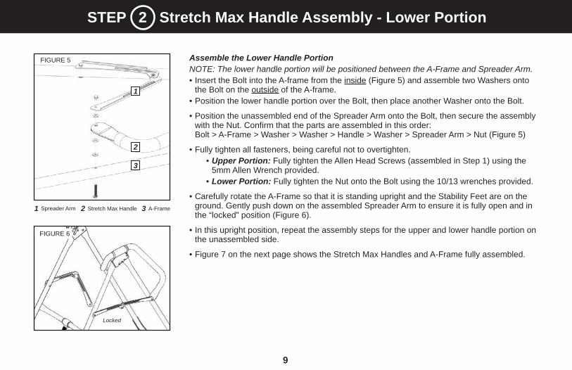
Assemble the Lower Handle PortionNOTE: The lower handle portion will be positioned between the A-Frame and Spreader Arm.• Insert the Bolt into the A-frame from the inside (Figure 5) and assemble two Washers onto
the Bolt on the outside of the A-frame. • Position the lower handle portion over the Bolt, then place another Washer onto the Bolt.
• Position the unassembled end of the Spreader Arm onto the Bolt, then secure the assembly with the Nut. Confirm that the parts are assembled in this order: Bolt > A-Frame > Washer > Washer > Handle > Washer > Spreader Arm > Nut (Figure 5)
• Fully tighten all fasteners, being careful not to overtighten.• Upper Portion: Fully tighten the Allen Head Screws (assembled in Step 1) using the
5mm Allen Wrench provided. • Lower Portion: Fully tighten the Nut onto the Bolt using the 10/13 wrenches provided.
• Carefully rotate the A-Frame so that it is standing upright and the Stability Feet are on the ground. Gently push down on the assembled Spreader Arm to ensure it is fully open and in the “locked” position (Figure 6).
• In this upright position, repeat the assembly steps for the upper and lower handle portion on the unassembled side.
• Figure 7 on the next page shows the Stretch Max Handles and A-Frame fully assembled.
FIGURE 5
FIGURE 6
1 Spreader Arm 2 Stretch Max Handle
1
3 A-Frame
2
3
Locked

10
1 Crossbar
2 Spreader Arm(s)
You may want to refer back to this diagram for reference throughout the assembly process.
RIGHT
LEFTBACK
FRONT
1
2
FIGURE 7
STEP 3 Familiarize Yourself with the A-Frame
• Position the A-frame on a level surface. Gently push down on the Spreader Arms to ensure they are fully open and in the “locked” position (Figure 7).
• Look for these temporary labels on your A-Frame, designed to assist you with the remainder of the assembly process. You may choose to remove them after you assembled your inversion table. RIGHT- Indicates right side as you are using the inversion table, not facing it. LEFT - Indicates left side as you are using the inversion table, not facing it. BACK - Indicates the back of the A-Frame / fully assembled inversion table. FRONT- Indicates the front of the A-Frame / fully assembled inversion table.

Assemble the Upper and Lower Portions of the Table Bed
NOTE: Do not detach the Bed Frame Extension from the clips.
• Locate the Table Bed Assembly Hardware Kit (HK1006)
• Lay the Upper and Lower Portions face down on the floor (Figure 9).
• Gently lift the base of the pre-assembled Bed Frame Extension to slide the Lower Portion and Frame onto the Upper Portion. Align the shaft of the frame into the plastic track of the Upper Portion (Figure 10).
• Align the bolt holes of the upper part of the frame (triangle-shaped area) to the bolt holes on the Upper Portion. Release the Bed Frame Extension so that it rests on top of the bolt holes (Figure 10).
• Reaching underneath, insert one of the shorter bolts through one of the holes in the Upper Portion and hold in place. Slide one of the Bed Frame Extension loops over the bolt and hand-tighten with a nut (Figures 11 & 11a). Repeat with the other shorter bolt.
• Reaching underneath, insert the longest bolt into the lower hole and hand-tighten with a nut.
• To fully tighten all three nuts to the bolts, insert the Allen Wrench into the bolt heads and tighten the nuts using a 10/13mm Open-Ended Wrench.
Lower Portion
Upper Portion
Bed Frame Extension
11
STEP 3 Table Bed and Bed Frame Extension Assembly
FIGURE 10
FIGURE 9
Lower Hole / Longer Bolt
Upper Holes / Shorter Bolts
12
FIGURE 11
Bed Frame Extension Loop2Shorter Bolt1
FIGURE 11a

• Familiarize yourself with the Roller Hinge and Cam Lock terms detailed above in Figure 12.
• For ease of assembly, rest the Table Bed against the Crossbar (Figure 13) at the front of the A-Frame.
• On one side of the Table Bed, lift the Cam Lock up all the way to unlock (Figure 14).
• In your other hand, hold one 3-Hole Roller Hinge at the Pivot Pin. With the Pivot Pin facing out (away from the Table Bed), slide the bottom of the Roller Hinge between the Cam Lock and the Bracket. TIP: Make sure that the Cam Lock is completely open when inserting the Roller Hinge, otherwise assembly will be more difficult.
• Engage one of the holes in the Roller Hinge over the Bracket Pin. Figure 16 shows the Roller Hinge installed correctly, with the Bracket Pin engaged in Setting C. NOTE: Refer to the Owner’s Manual for an explanation of the hole settings. If you are unsure, use Setting C to start.
• Push down on the Cam Lock (Figure 15) to lock it and secure the Roller Hinge.
• Repeat on other side. Make sure the Roller Hinges are in the same hole setting on both sides.
STEP 4 Roller Hinge Assembly
CBA
1
12
FIGURE 13
FIGURE 14 FIGURE 15
FIGURE 16
Unlocked Locked
Cam LockPivot Pin
Bracket
FIGURE 12
NEVER disassemble the Roller Hinge Pivot Pin.
WARNING!
Bracket Pin1

• Face the front of the A-Frame where the Crossbar is located (refer to Figure 17 to determine A-Frame Front).
• Grasp both the Roller Hinges, right above the Cam Lock, and lift the Table Bed. Allow the top of the Table Bed to rotate toward the floor, so that the back of the Table Bed is now facing you and the top of the Table Bed is in front of the Crossbar (Figure 18).
• Lower each Roller Hinge Pivot Pin into the A-Frame hinge plates, one side at a time (Figure 19). The Self-Locking Hooks will open to allow the Pivot Pin into the Hinge Plate slot, then automatically snap closed over the Pivot Pin. TIP: You may need to push outward on the Hinge Plate in order for the second Pivot Pin to lock in place.
• Make sure that each Pivot Pin is seated at the base of the slot in the Hinge Plates, and that the Self-Locking Hooks have closed over both Pivot Pins (Figures 19a & 19b).
• Rotate the Table Bed into the use position (Figure 20). Ensure that it rotates smoothly.
STEP 5 Attach the Table Bed to the A-Frame
13
FIGURE 17
FIGURE 18
FIGURE 19 FIGURE 20
FIGURE 19a TOP VIEW
FIGURE 19b INSIDE VIEW
Failure of the Self-Locking Hooks to close over both Roller Hinge Pivot Pins is an indication of improper assembly and if not corrected
could result in serious injury or death!
WARNING!
FRONTBACK

• Facing the front of the A-Frame, hold the Main Shaft in your left hand with the height markings facing up. Slide the end of the Main Shaft into the Main Shaft Housing (Figure 21), located at the base of the Table Bed.
• With your right hand, pull out the Height-Selector Locking Pin (Figure 21a) to allow the Main Shaft to slide in further and release in the desired height setting. Refer to the Owner’s Manual for more information on selecting your height setting.
• The Main Shaft MUST REST against the Crossbar of the A-Frame (Figure 22). IMPORTANT: The Crossbar prevents the Table Bed from rotating forward when the user steps on the Ankle Comfort Dial. If the Main Shaft does not rest on the Crossbar as shown in Figure 22, then the Table Bed has been assembled backwards onto the A-Frame. This MUST BE CORRECTED before use.
• Test the inversion table by hand for smooth and steady rotation (Figure 23) and ensure that all fasteners are secure.
STEP 6 Assemble the Main Shaft to the Table Bed
14
FIGURE 21
FIGURE 22
FIGURE 23
FIGURE 21a
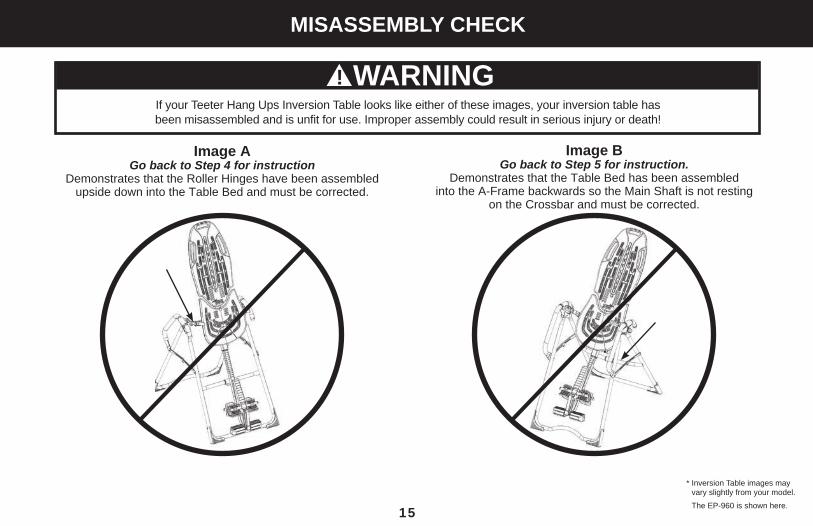
Image B Go back to Step 5 for instruction.
Demonstrates that the Table Bed has been assembled into the A-Frame backwards so the Main Shaft is not resting
on the Crossbar and must be corrected.
Image A Go back to Step 4 for instruction
Demonstrates that the Roller Hinges have been assembled upside down into the Table Bed and must be corrected.
If your Teeter Hang Ups Inversion Table looks like either of these images, your inversion table has been misassembled and is unfit for use. Improper assembly could result in serious injury or death!
MISASSEMBLY CHECK
* Inversion Table images may vary slightly from your model.
The EP-960 is shown here. 15
WARNING!

Attach the EZ-AngleTM Tether (OPTIONAL)
• The tether will come pre-assembled to the A-Frame.
• Unfold the adjustable tether and clip it to the U-Bar on the underside of the Table Bed (Figure 24).
• The EZ-AngleTM Tether features color coded angle markers to assist in finding your preferred pre-set angle of rotation:
20° / Gentle Inversion Green stripe must show in the center of the sliding buckle.
40°/ Moderate Inversion Orange stripe must show in the center of the sliding buckle.
60° / Advanced Inversion Red stripe must show in the center of the sliding buckle.
90° / Full Inversion Remove the carabineer from U-Bar to enable rotation to full inversion.
Attach the Head Pillow (OPTIONAL)
• Attach the Head Pillow by securing the Velcro Straps through the holes in the Table Bed (Figure 25). The position of the pillow can be adjusted depending on the user.
STEP 7 Attach the Accessories
16
FIGURE 24
FIGURE 25
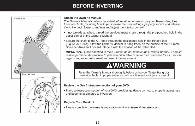
Attach the Owner’s Manual The Owner’s Manual contains important information on how to use your Teeter Hang Ups Inversion Table, including how to personalize the user settings, properly secure and release the Ankle Lock System, and test and adjust the rotation control.
• If not already attached, thread the provided metal chain through the pre-punched hole in the upper corner of the Owner’s Manual.
• Secure the chain to the A-Frame through the designated hole in the Hinge Plate (Figure 26 & 26a). Allow the Owner’s Manual to hang freely on the outside of the A-Frame Spreader Arms so it doesn’t interfere with the rotation of the Table Bed.
IMPORTANT: Once attached to the A-Frame, do not remove the Owner’s Manual. It should remain permanently attached to your inversion table to serve as a reference for all users in regards to proper adjustment and use of the equipment.
Review the Use Instruction section of your DVD
• The Use Instruction section of your DVD provides guidance on how to properly adjust, use and become acclimated to inversion.
Register Your Product
• Please complete the warranty registration online at teeter-inversion.com.
WARNING!Read the Owner’s Manual thoroughly before using your Teeter Hang Ups Inversion Table. Improper settings could result in serious injury or death!
BEFORE INVERTING
17
FIGURE 26
FIGURE 26a