Embed Size (px)
Citation preview

-• -ter. ^-^Y -^
< Copy
1956 RM^sL56H27
CLASSIFICATION CANCELLEDr I—V w74 Trruvtre( PUBLICATIONS
"-AtE ey
'JCLASsS.IFICAT+ION ORANGE
NACAL1 ^
By authority of - ,u1.¢':.",
t RCH MEMORANDUMfor the
U. S. Air Force
LONGITUDINAL AND LATERAL STABILITY,
COYTROL CHARACTERISTICS, AND VERTICAL-TAIL-LOAD
1XI SUREIviENTS FOR 0.03-SCAM MODEL OF TM AVRO
CF-105 AIRPLANE AT MACH NUMBER 1.41
By M. Leroy Spearman, Ross B. Robinson,and Cornelius Driver
Langley Aeronautical LaboratoryLangley Field, Va.
ofmaemer TUMrTMRUTnb-rized person is proMbite y law.
NATIONAL ADVISORY COMMITTEEFOR AERONAUTICS I
ILE COPY
WASHINGTON To be returned to
AUG 11 0 1956
V
https://ntrs.nasa.gov/search.jsp?R=20050028458 2018-06-08T13:00:59+00:00Z

NACA RM SL56H27
RESEARCH MEMo.RANDUM
for the
U. S. Air Force
Lo.NGrruDINAL AND LATERAL STABILITY, '
Co.NTRo.L CHARACTERISTICS, AND VERTICAL-TAIL-Lo.AD
MEASUREMENTS Fo.R o..o.3-SCALE Mo.DEL o.F THE AVRo.
CF-lo.5 AIRPLANE AT MACH NUMBER 1.4l
By M. Leroy Spearman, Ross B. Robinson, and Cornelius Driver
SUMMARY
An investigation has been made in the Langley 4- by 4-foot supersonic pressure tunnel at a Mach number of l.4l to determine the aerodynamic characteristics of an o..o.3-scale model of the Avro CF-lo.5 airplane. The investigation included the determination of the static longitudinal and lateral stability, the control and the hinge-moment characteristics of the elevator, the aileron, and the rudder, as well as the vertical-tail-load characteristics.
The results indicated a minimum drag coefficient of about 0..0.270., and a maximum trimmed lift-drag ratio of about 4.25 which occurs at a lift coefficient of o..l6.
The directional stability decreased with increasing angle of attack until a region of static instability occurred above an angle of attack of about 90 •
INTRo.DUCTION
At the request of the U. S. Air Force, an investigation of the aerodynamic characteristics of the Avro CF-lo.5 airplane has been undertaken by the National Advisory Committee for Aeronautics.
, . ·"L .. ~.;:::;1J(i >',: >i!nlfnWarrW ~ .. ,:,: ;,':\,1 t'::{:?X<::,~{~::~j\:~~~>;:,:: ,:-, <~, ,,;' ,:~~:t
~. ...- • I
• ,PO -;;/ ,:;.~;'~ t.- t ,-
, I
2 NACA RM SL56H27
! This airplane is a twin-jet-propelled tailless fighter design having
a cambered 61.40 delta wing with a thickness ratio of 3.5 percent. The inner wing leading edge is drooped 80 , the outer wing leading edge is extended 10 percent of the wing chord and drooped 40 , and a leading-edge notch is located at about the midsemispan of the wing. Twin inlets are located on the sides of the fuselage fO~fard of the wing leading-edge juncture. A swept vertical tail is used to provide the directional stability. Directional control is provided by a conventional rudder, whereas the longitudinal control and lateral control are provided by separate elevators and ailerons on the wing trailing edge.
The purpose of the present paper is to present the results of an investigation of an 0.03-scale model of the Avro CF-105 conducted in the Langley 4- by 4-foot supersonic pressure tunnel at a Mach number of 1.41. In addition to six-component results for the model, three-component results were obtained for the vertical tail, and hinge-moment results were obtained for the elevator, the rudder, and the aileron.
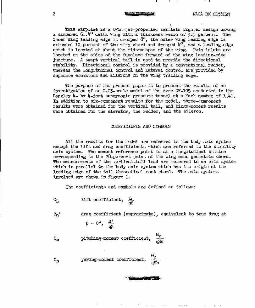
COEFFICIENTS AND SYMBOLS
All the results for the model are referred to the body axis system except the lift and drag coefficients which are referred to the stability axis system. The moment reference point is at a longitudinal station corresponding to the 28-percent point of the wing mean geometric chord. The measurements of the vertical-tail load are referred to an axis system 1'rhich is paraJ.lel to the body axis system which has its origin at the leading edge of the tail theoretical root chord. The axis systems involved are shown in figure 1.
'c L
The coefficients and symbols are defined as follows:
lift coefficient,
CD I drag coefficient (approximate), equivalent to true drag at
f3 = 0 0,
DI qS
pitching-moment coefficient,
yawing-moment coefficient,
~ qSc
Mz qSb
""j T· 2!h£8
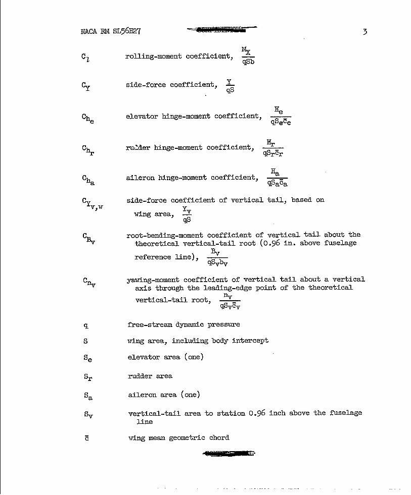
NACA RM SL56H27 -=T8UiiI EEl ± i 3
C~
Cyv"r ,
CBv
CIlv
q
S
rolling-moment coefficient,
side-force coefficient, L qS
Mx qSb
elevator binge-moment coefficient,
ru~der hinge-moment coefficient,
aileron binge-moment coefficient,
side-force coefficient of vertical tail, based on
wing area, Yv qS
root-bending-moment coefficient of vertical tail about the theoretical vertical-tail root (0.96 in. above fuselage
reference line), Bv
yawing-moment coefficient of vertical tail about a vertical axis through the leading-edge point of the theoretical
nv vertical-tail root, qpvcv
free-stream dynamic pressure
i-Ting area, including body intercept
elevator area (one)
rudder area
aileron area (one)
vertical-tail area to station 0.96 inch above the fuselage line
,·ring mean geometric chord
11070 n
I • , ••
• • ••
4
ce
cr
ca
Cv
b
bv
a.
13
°e
or
°a
LID
Cy 13
--- ~--- -
NACA EM SL56H21
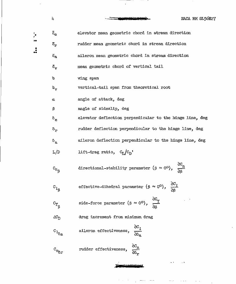
elevator mean geometric chord in stream direction
rudder mean geometric chord in stream direction
aileron mean geometric chord in stream direction
mean geometric chord of vertical tail
vTing span
vertical-tail span from theoretical root
angle of attack, deg
angle of sideslip, deg
elevator deflection perpendicular to the hinge line, deg
rudder deflection perpendicular to the hinge line, deg
aileron deflection perpendicular to the hinge line, deg
lift-drag ratio, ~/CnI
directional-stability parameter (13 ~ 00 ),
effective-dihedral parameter (13 ~ 00 ),
side-force parameter (\3 ~ 00 ),
L'CD drag increment from minimum. drag
aileron effectiveness,
Cnor rudder effectiveness,
F PEEMI

NACA RM SL56H27 ,
= .lfiiFRlilTPb 5
Choa aileron binge-moment parameter,
rudder binge-moment parameter,
MODEL AND APPARATUS
Details of the model are shown in figure 2 and its geometric characteristics are given in table Ie A photograph of the model is presented in figure 3.
The model had a modified delta wing I-Tith a leading-edge sweep of 61.40 , an aspect ratio of 2, a taper ratio of 0.089, and vTas composed of 3.5-percent-tbick cambered sections. The outer wing leading edge was extended 10 percent of the chord and drooped 40 • The inner Ifing leading edge I-Tas drooped 80
• A leading-edge notch was located betlfeen the inner and outer portions of the I-ring at about the midsemispan point.
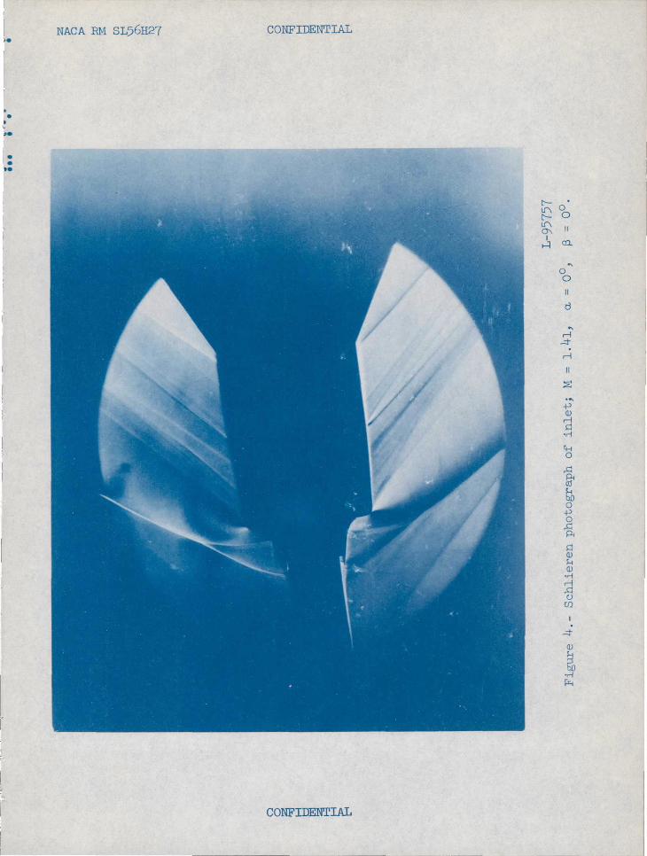
The model I-Tas equipped Ifith twin side inlets that were ducted to a single exit around the sting at the base of the model. For most of the investigation the inlets I-Tere open to permit air flow through the model. In addition, for one test, faired plugs (outlined in fig. 2(a)) vTere used to close the inlets so that some results might be obtained Idthout f'lmT through the ducts. The internal flow characteristics for the configurations having open inlets were not determined since the internal lines of the model were such that an accurate determination of the characteristics could not be made. A schlieren photograph of the flow characteristics at the open inlet is shmm in figure 4.
One test I-Tas made vri th transition fixed on the model. The transition strips, l-Tbich consisted of one-quarter inch I-Tide strips of No. 60 carborundum particles adhered to the surface vri th shellac, lfere located about 1 inch rearlfard of the fuselage nose and along the 10-percentchord lines on both surfaces of the ldng and vertical tail.
The basic model had a nose cone included angle of 500 • One test l-Tas made ldth a slightly longer nose having a cone angle of 300 • (See fig. 2(a).)
The external lines of the model fuselage were altered slightly from those of the airplane in that a portion of the afterbody on the underside of the fuselage l-Tas enlarged to accommodate the sting support.
,6dmEI.±£*

• • • ••
• • ••
6 8611t !! '.10* NACA RM SL56H27
A rudder, tvro elevators, and a single aileron on the right 'toling only were provided. These controls were manually adjustable and were equipped id th strain-gage beams. The vertical tail was equipped with a three-component strain-gage balance designed for the purpose of determining the side force on the tail, the root bending moment of the tail, and the tail yawing or tvlisting moment. Forces and moments for the model proper i-rere measured by means of a six-component internal strain-gage balance. The model was mounted on a remotely controlled rotary sting in order to facilitate testing at combined angles of attack and sideslip.
TESTS
Test Conditions
The tests were conducted at a Mach number of 1.41, a stagnation pressure of 10 pounds per square inch, and a stagnation temperature of 1000 F. The dei'l'point was maintained at -250 F or less to prevent adverse condensation effects.
The Reynolds number based on the idng mean geometric chord i'TaS
2.69 x 10⁴• The dynamiC pressure for the test was about 620 pounds per square foot.
-40 0 Tests 1-rere made through an angle-of -attack range of about to 15 at 13::::: 00 and through a -1;120 sideslip range at nominal angles of attack of 00 , 4.30 , 8.70 , 130 , and 15.20 • The results., except i-There noted, are for the open inlet configuration.
Corrections and Accuracy
The angles of attack and sideslip and the control surface angles have been corrected for the deflection under load. No corrections for internal flow effects or base conditions have been applied to the drag measurements. It is estimated, however, on the basis of results for similar arrangements, that the drag corrections would result in an increase in the minimum drag coefficient of about 0.004 for the open inlet configuration and in a decrease in the minimum drag coefficient of about 0.002 for the faired inlet configuration.
The estimated errors in the individual measured quantities are as follows:
~. 0000000 . . o 0 0 0 0 000
("~r -lJ Q 0 0 0
(!186M nZ!l!Sl@

• • • ••
• • ••
NACA RM SL56H27
Cm ••• Cn •
C7, 0
Cy • • •
Cbe ••• chx
II LA
o 0 0 0 0 0 • • .00 0 .00 0
o • • G 000000 00000
0000 0000000
000.0 ••••••• 0 •••• 0 ••
0" 0000.0 •• 0000000
••• 00000 •••••• 0.
Cha 0 ••••••• 0 ••• 00 • 0 0
CYv 1-T • • • • • 0 0 0 0 0 , CBv ......... 00.0.0000 o 0 0 0 0
en ...... 0 • v 000 •••• 000.0000.
0" deg /3, deg • 0e' deg or' deg
• • • • • • • 0 • • 0 •
• •• ooeooo •• ooo 00.0000
• • • • 0 • •
•••• 00 •• 0 •• 0 •••• 0.00 •• 0
0a' deg •• • • • • o 0 • • 0 • • 0 00 ••• 000
RESULTS
The results are presented in the following manner:
7
±O.0005 -±000005 i:O.0002 -1:000057
±Oo0070
i:000025
-j;().0064
i:O.0010
to.0013
i:O.0016
-1:0.2 -±O.2 ±Co3 -j;().3
i:O.4
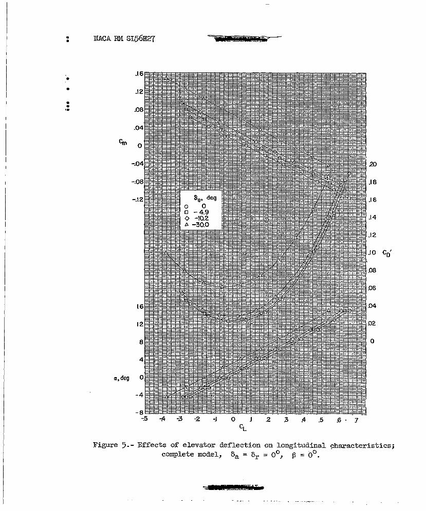
Figure Effects of elevator deflection on longitudinal charac
teristiCS; complete model, 0a = or = 00 , /3 = 00 000000 5
Effects of fuselage nose and inlet fairings on longitudinal characteristics; oa = oe = or = 00 , /3 = 00
0
Effects of fixed transition on aerodynamic characteristics o • • 6
of complete model in pitch and sideslip; oe = oa = or = 00 7 Effects of inlet fairings on aerodynamic characteristics
in sideslip of complete model and the wing-fuselage combination; oa = 0e = or = 00
0 • • • 0 • 0 • • • • • • • • •• 8 Effects of fuselage nose shape on aerodynamic character-
istics in sideslip at various angles of attack; complete model, oa = oe = or = 00 • • • • • • 0 • • • • • • • • • • • •• 9
Effects of rudder deflection on aerodynamic characteristics in pitch; complete model, oa = oe = 00 , /3 = 00 • • • • • • 10
Aerodynamic characteristics in Sideslip at several angles of attack of complete model with various rudder deflections and of wing-fuselage combination; oa = oe = 00 • •
JlJapIEzum
o ., 0 0 11

, • , I.
• • I.
8 >4 i2 NACA RM SL56H27
Figure Rudder hinge-moment characteristics in sideslip at
several angles of attack; 0e = 0a = 00 • • • • • • • • • • • • •
Effects of aileron deflection on aerodynamic charac-teristics in pitch; complete model, 0e = or = 00 , ~ = 00 ••••
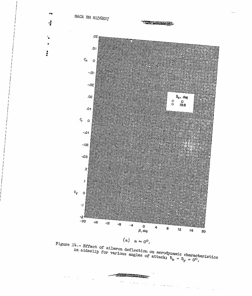
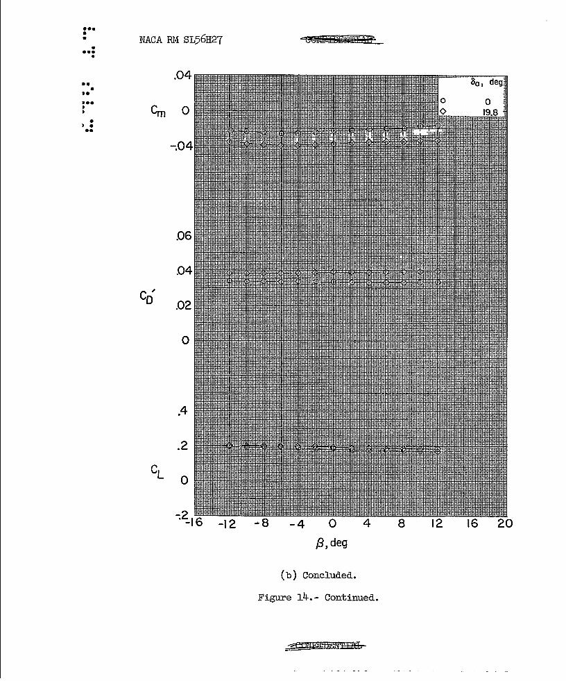
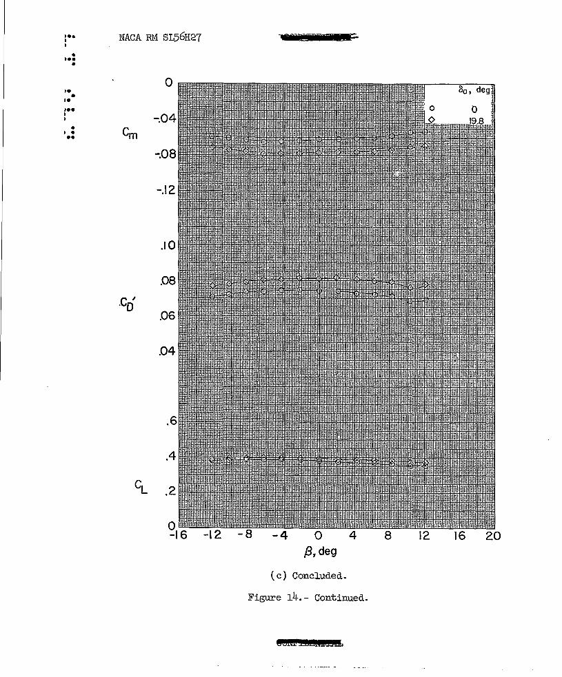
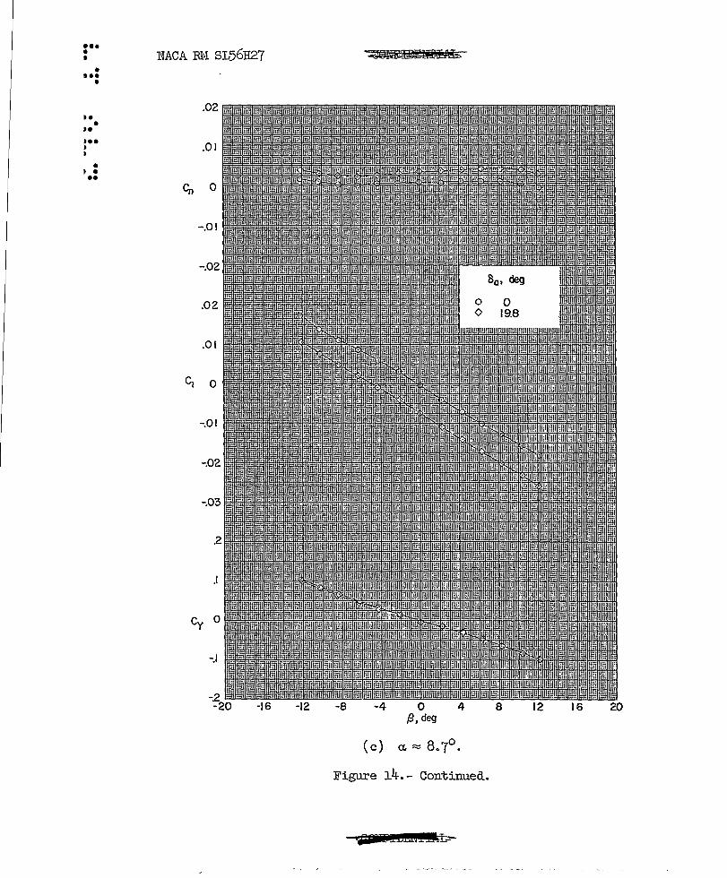
Effect of aileron deflection on aerodynamic characteris-tics in sideslip for various angles of attack; o e = or = 0° . . . . . . 0 • 0 0 0 0 0 0 • • 0 • • 0 0 0 0 0 0 0
Aileron hinge-moment characteristics in sideslip; complete model, 0e = or = 00 • • • • • • • • • •
Effect of angle of attack on variation of side-force coefficient of vertical tail based on wing area id th angle of sideslip; 0e = 0a = or = 00 • • • • • • 0 0
Effect of rudder deflection bn variation of side-force coefficient of vertical tail based on wing area with
o 0 0 0 0 0
12
13
14
l5
16
angle of sideslip for various angles of attack • • 0 • 0 • • •• 17 Effect of angle of attack on the variation of root-
bending-moment coefficient of vertical tail with angle of sideslip; 0e = 0a = or = 00 • • • • • • • • • • • • •• 18
Effect of rudder deflection on variation of rootbending-moment coefficient of vertical tail with angle of sideslip for various angles of attack •
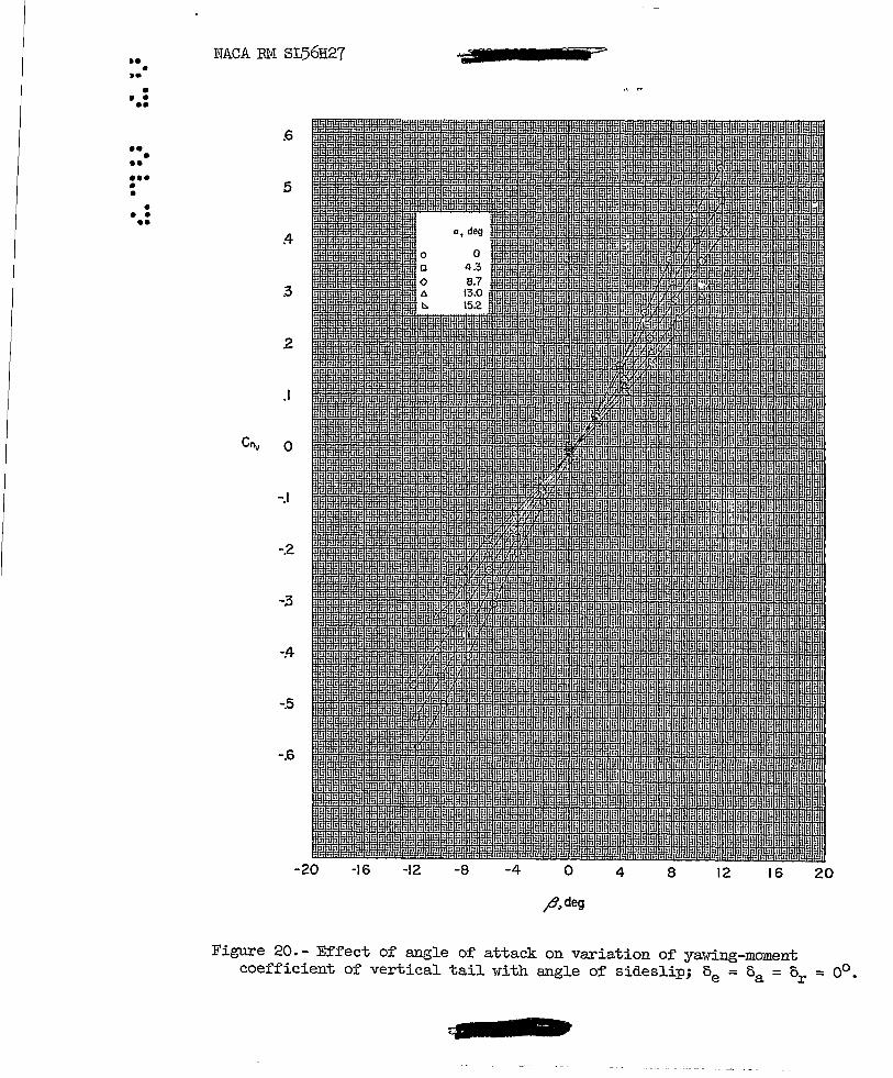
Effect of angle of attack on yaidng-moment coefficient of vertical tail idth angle of sideslip; 0e = 0a = or = 00 •• • • • • • • • • • • • • •
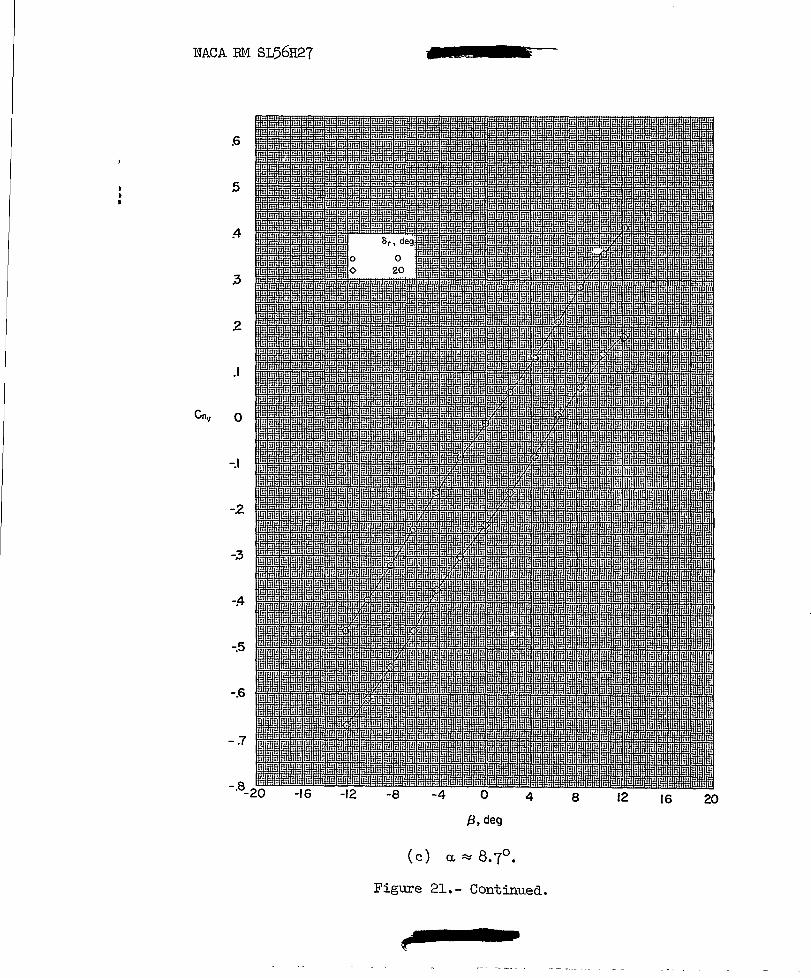
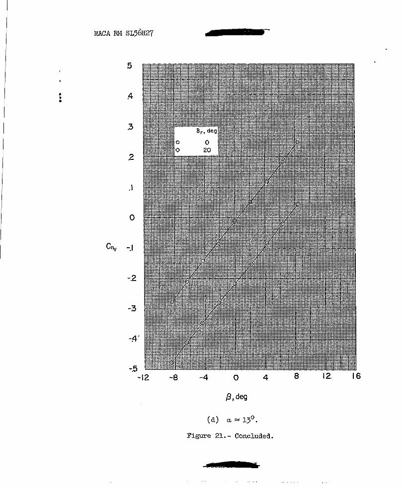
Effect of rudder deflection on variation of yaidngmoment coefficient of vertical tail with angle of
00000000 19
O.ftOOOOO 20
sideslip for various angles of attack ••• • • • • • • • 0 • 0 21 Trim longitudinal characteristics; complete model,
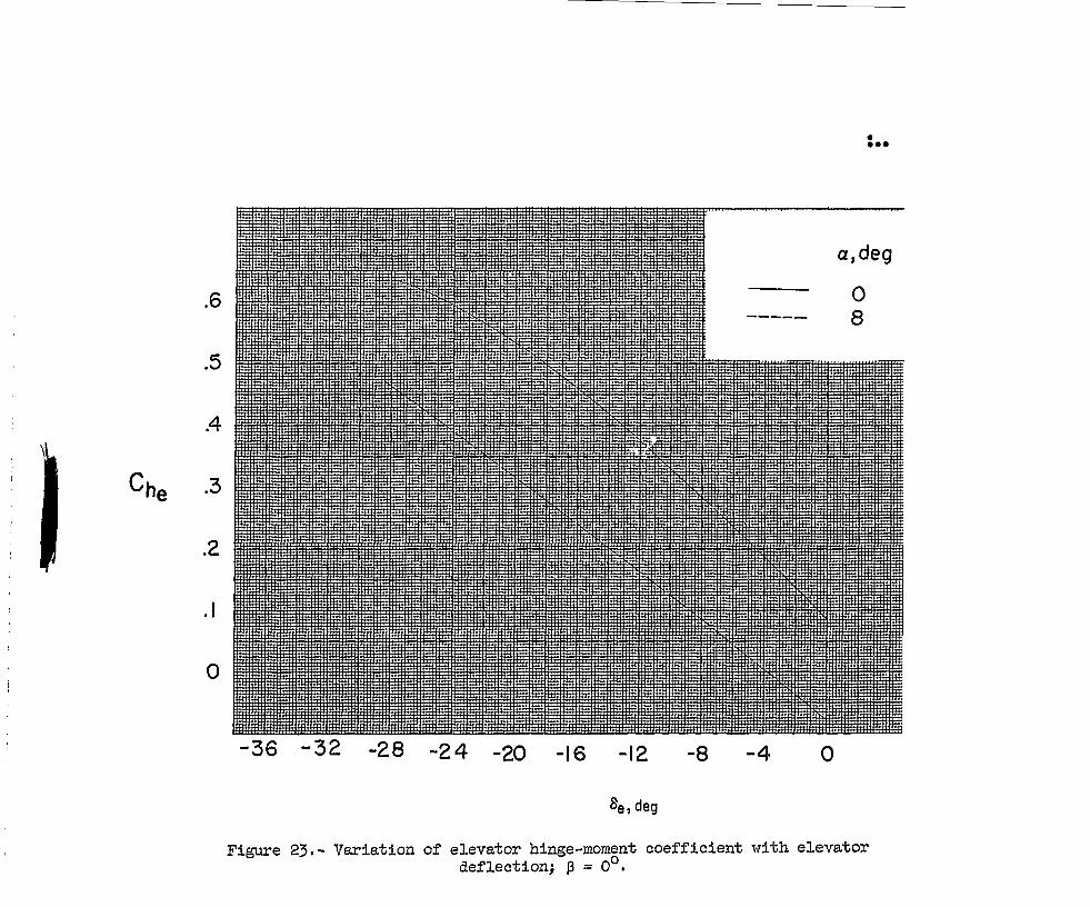
open inlets (uncorrected drag) • 0 0 • • • 0 •••• 0 0 0 • •• 22 Variation of elevator hinge-moment coefficient with
elevator deflection; ~ = 00 • • • • • • • • • • • • 0 • • 0 23 Characteristics of drag due to lift; complete model~
open inlets, 0e = 0a = or = 00 , (uncorrected drag) 24 Variation of lateral and directional stability charac-
teristics for open and faired inlets for complete model and idng-fuselage combination. 0a = 0e = or = 00 •••• 25
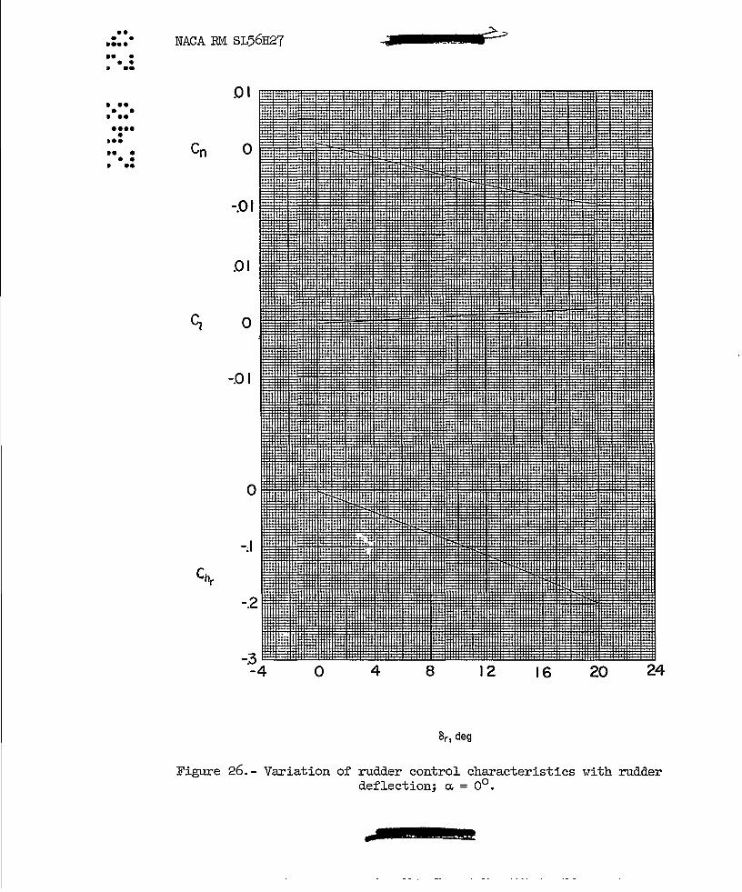
Variation of rudder control characteristics with rudder deflection; ~ = 00
0 • • • • • • • • •
Variation of aileron control characteristics with aileron deflection; ~ = 00 • • • • • • • • • • •
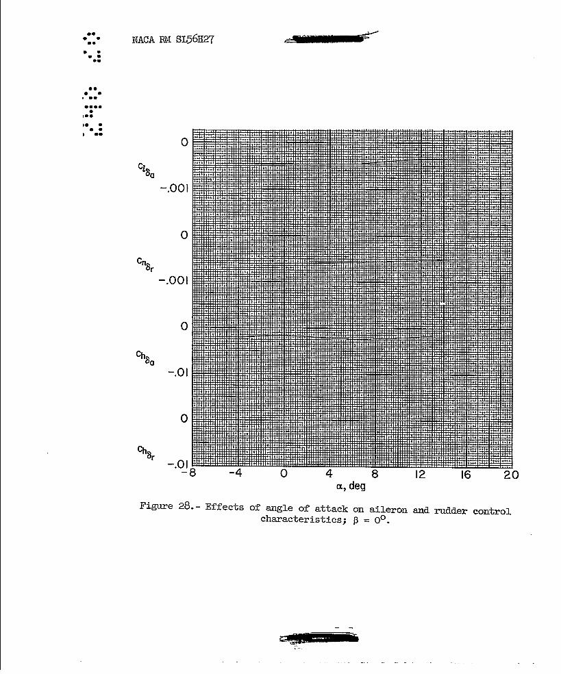
Effects of angle of attack on aileron and rudder control characteristics; ~ = 00 • 0 • • • • •
aiU~Em¥STU
0000000
27
28

•• • •• ••• • •
• • • ••
NACA RM SL56H27 su.,,'i .... 9
A limited analysis of the results has been made and some points of general interest have been noted. The uncorrected minimum drag values, are about 0 .0230 with the inlets open and about 0 .0290 with the inlets faired (fig. 6). It is est~ted, on the basis of investigations of similar configurations, that the corrected minimum drag coefficient would be about 0.0270.
A maximum trimmed lift-drag (LID) ratio of about 4.25 was obtained at a lift coefficient of 0.16 (fig. 22). For an assumed wing loading of 40 pounds per square foot this imuld correspond to an altitude of about 57,000 feet. A lift coefficient of 0.32 was obtained with the maximum elevator deflection of -300 (fig. 22). Hence, if sufficient power is assumed to be available, a normal acceleration of 2g r s could be attained from an initial trim position corresponding to the maximum LID (~= 0.16). .
The directional stability results (fig. 25) indicate that about 63 percent of the total tail contribution to c~ is required to over-
come the unstable moment of the wing-fuselage combination at ~ = 00 •
This, of course, is caused primarily by the far rearward center of gravity (moment reference point) which results in a large unstable fuselage moment and a short tail moment arm. The directional stability Cn/3
decreases with increasing angle of attack until a region of static instability occurs above ~ R:: 90 • This reduction in Cn/3 results pri-
marily from a loss in the vertical-tail contribution and, to some extent, to an increase in the instability of the wing-fuselage combination. The loss in tail contribution probably results primarily from sidewash changes induced at the tail by vortices emanating from the rather square upper corners of the fuselage. The directional stability for the prototype airplane may be further aggravated by the additional losses in tail contribution to be expected from aeroelastic effects and, with increasing Mach number, by the decrease in tail lift-curve slope.
Fairing the inlets had little effect on the tail contribution to Cn/3 (fig. 25) but did provide small positive increments of C~ for
both the tail-on and tail-off configurations •
..... nT 'Wilf

,. • ,.
t •• p I>
• It •
••
10 ilUltlRLIi££& NACA RM SL56R27
The control characteristics of the elevator, the rudder, and the aileron indicated positive control effectiveness that I"as reasonably linear lvith control deflection and decreased slightly with increasing angle of attack.
Langley Aeronautical Laboratory, National Advisory Committee for AeronautiCS,
Langley Field, Va., August 13, 1956.
"W\..-R~~ M. Leroy Spearman
Aeronautical Research Scientist
k4~ Ross B. Robinson
Aeronautical Research Scientist
~£J~ Cornelius Driver
Aeronautical Research Scientist
Approved: ~~ John V: Becker
Chief of Compressibility Research Division
pf

NACA RM SL56H27 ':::.i!II' Iii oj?
TABLE I.- GEOMETRIC CHARACTERISTICS OF MODEL
vling: Area, sq ft • • • Span (projected), in. Mean geometric chord, in. Sweep of quarter-chord line, deg Sweep of leading edge, deg Aspect ratio Taper ratio • Dihedral, deg • Incidence, deg Thickness ratio, percent
Vertical tail (theoretical, with root station 0.96 inch above fuselage reference line): Area, sq ft • Span, in. Mean geometric chord, in. Sweep of leading edge, deg Aspect ratio (panel) Taper ratio •
Elevator: Area, sq ft • Span, in. Mean geometric chord, in.
Rudder: Area, sq ft • Span, in. Mean geometric chord, in.
Aileron: Area, sq ft • Span, in. Mean geometric chord, in.
o 0
?
II
1.1025 18.000 10.878
55 61.4 2.04
0.089 -4 o
3.5
0.143 4.635 4.872 59.3 1.04
0.298
0.048 3.665 1.89
0.0343 3.615 1.422
0.030 3.605 1.261

a • •
NAeA RM SL56H27
____ 01
~~r Relative Wind I ..
f3 X .J---------::;;:
L
My
a X--~------~~~~~~~----
Relative Wind .. ----.::::::::::::::::=_ ---11"-01
z
(a) Stability axes.
Figure l. - Axis notation. Arrmrs indicate posi ti ve directions 0
cCRlLml£!Wsz-

l'lACA EM SL56H27 4GI6:: ; ; m,,!) i • iIIT
x~~ a
• Relative Wind
z
(b) Body axes.
Figure 1.- Concluded •
.::I! •• n T 7~

9.000
,
140
Chord plane
Fuselage station 0
/:
Fuselage station
o
Fuselage 0.114 reference line -
7.110 -I "',
c:J 1.9:~ 13.07
• ••••• • • • • • • ••• • • • ••
16.12
......... ..........
3.253 t
______ ,.;-~----I C = 10.884---\
~onnent reterence
- I 0.
9001'" -~6.050-~ """==------------25.388--------------1
(a) Three-view drawing .of model.
Figure 2.- Details of model. All dimensions in inches unless otherwise noted.

Fuselage ~ --+J < r-0.808
16.200
6\.4 o
(b) Details of wing.
Figure 2. - Continued.
0.144
1.44
: .. • • • • • : ..
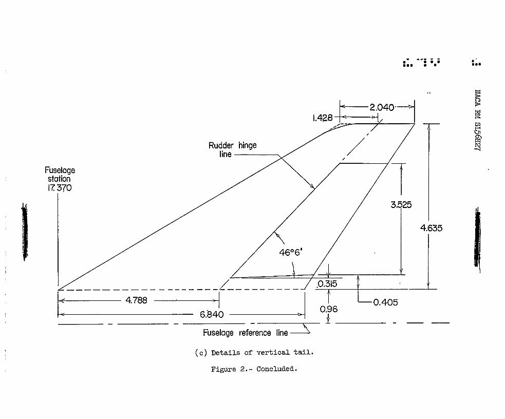
Fuselage station 17. 370
Rudder hinge line-----....
_______________ ___ L _____ ___ _ k 4.788.. ,I J ~ 6.840 ------
Fuselage reference line--=s
(c) Details of vertical tail.
Figure 2.- Concluded.
.- -~i i i • ••• • • • ••
3.525
4.635
0.96 0.405
1 __ -

jr
zn
rrnxN-J
iw
0O
H
9Hr
QO
dt^J
Figure 3.- Photograph of 0.03-scale model of Avro CF-105. L-93^+65
0.`n 0^ n
a co-
0 0
t3
0
0
dp
aD0
0
PA
a^
0
U
bD.r{
NACA Ell SL56H27 CONFIDENTIAL
CONFIDENTIAL
• •
• •
• • I.
NACA RM SL56H27
Gn
20
.18
.16
.14
.12
.10 C I D
.08
.06
.04
.02
0
a,deg
~ -.3 -2 -J 2 .3 .4 .5 .6· 1
Figure 5.- Effects of elevator deflection on longitudinal ~haracteristics; o '0 complete model, 0a = or = 0, ~ = 0 •
II ""!BMiif:iu.

.6
.5
.4
.3
11i!!l!l 1!Ii lin ill! l1!: !lll!!!I!1 ill! !lH!iW!11II II! III: 1IIII'IIIi1l11lmITiffil 11: In ill 1 ; IT ·11· .... " .............. '111 '1 1 .... I!il '1\ I' \. :;" ....... I" '1"1 II I "1""1 I,,: im mi 1:H:* II\: :iI LI :Hi \H: I. .1 I ilP !I!I iii! ! Ii III: F .:::11
! IIUl! ililliii HI I'll II. I ":I!ll ql ,: I \ I !I I ! 1\ 'il! [P! Hi! ! II ,illig i ·m III! III II I iii HI I I Ii' 1 II h i \ H 1!PiIW : HlUUl! I Ii !II Iii I . i rmt· I I ,!I! I'n!! ilii IIllm [ 0 Iii! HH I I i! n, Hi I . 1 dl I nil !ill III II :-II IIlI IIIl I 0 .ill!iill I II'I'! I' II'!! ! '1' I' I, Iii! W! i:1 1 IIi! jill I F '(Ii 111'1"1/11 1:11' I 1/ 1111 1l:!1 i A 'II In:. • :lj 0 I. II \ I '" ,1 f I II I .1. I d'X 1111 .. II H I I 11,1. v
If([ nlll! Ii\! ~! " .in H,!' .\\, II I iii! P!! !n! ii!: ill! iP! I,I! 1'J;!li!!l1)J11 HI I'll I I ':IIIHlIII': Wi: .Intl '" I ':L ,!,. " 11 ...... H~' ,." .... It \ It. ~ •• II IUIII:~ .. II.J I. II J I., I I ..... A il !Iii \'!I' 1'1 11\' \lliH\' I'I! H!i iii: IIH I iii' r 'I\!i iii: ili\' llli p': l' j I'·:·'N,!! 'I:! i!'11 :1111111:l1! iiF i 01 .... I II ... • It •• to " I •• lif ".1 • I ,HI. tt '.0.. I. lUI, ,.I ,
• • • f f f.' • • f.
t 8e, deg .:
o -4.9
-10.2 -30.0
i I
ft Iii! nil I Iii !ill !iii lin lHi iiii I!H Iii HI!! IIll i!li "Ii ! III! dli i lr ~I 't' lW iW i Pi: i:n :ill iiii iii: Wi iln :m jll,'1 nIl!" I " !II I 1IIIHi II' 11111111 Ill! It I i !!I'I 'Il: I!!i i!!1 Ii !il' i iil l '11'111 :I!: .... II'!: i!ll ,I ....... 1, 'ii ......... 1 .. In' :111 • I • I iI' III I • I .. , ..... I ,1,11111.1.1 .... I ..
1::1 i!!:" I'i I' Iii Ill! PI! ,'i:: pp Illi I!II! 'I I' II. II!!! 1111 lill II lijill!, '1 ' !til iii! H!! il:: lii! 'iii l::! im !iIi i!I'i I!! 'I. \in ,j; t h .u. '1 • .Ill ., .nl n' lill III "I I ,I:t: , .1 '~';'" I It 01,1 ,.iiit ....... q ,I • t.11
j.:: p.! ; I: till !,,: ::.1 Ip: !!JI 1!1I 11 III' I 11111\ :lil' I I Ill: 'Il' Ill' : II Iii II I I" I\il ilil :::; ;I,H !'I": 1111 IJ!: ::11 lil' l W; 1111 I':' .II I n' ;,:: ::~~ :.:t :'.: :W IL. III I I I t:1I :', I • ;: ,:" ; I;. :!tl ::11 :h: till In: :::1 0:· to : .::~ :: ; .Itlt :1": III . 1111 III: I::: IIj: !Ii '1'11 lUI '! 'Ii' II. I\li II . 1011111 'lit! 'I III 'ji:!' I: p: Hil: '1\1'111111 ,ql :11; \':1\ :lli I,ll nl\ II:: I I tltt: H 1f';I" 1:1: 1::1 :: 1 H. IHl t (' i~L I d III II I 11111 I nt ;:;1 .1 111 ::.: ':p :n l' ttl: :::: ::::
ilil gil j I: Ii I !m ntH~Nlil\ lHi : .. iili I! '1 ' i lii!!ili l! iii; 1.'1' I iii Ii! I I' iU ''1' : i' liE im iff: Pll l!!I im itti !iii I q
Ill! iii"l I \ I Ii II I Illl :H: tili \'i ~ I Ii,' I II' I : 1'11'. 1\ I' ITI j I .1 ::1' Ill! : II I! j' II! jll. I:'! illl' ]1\1111 !P! ::::! I , • I. :;: %11 ., 1", • IrQ. 111 1 1 ••• " ••• • I III. 1J • I " % HI ••••• "
IIi!!! Iii: I11I 1m Ii Il!lf ',':ITI: lIi \ I'.ll I Iii' :\\'\ '''I I I I I :' .• '\ '\' I: [' ! ill ;1 1)1 II:! lili P,! iii! 11'j! !I"I 'PI H!. in I .,1. :1 HI.: t • I I till I I .!J B t .t ,Ip In. ,I,. • I I ,f
. iil! 1!IPI!!! II:!! !tl'J' ,!il I '\',. I I' I,illl 1111 111'1 J • I, I " • II !II, 'I' \ Ill: !ill !11,m: 1'1\; ITII' ,'!,'! ':1" 2
II ... u:lt:u .n;: n, :0 .. I, , tnt:l: • I j, d .• ,d· ,'\of ... It I. III
• 11\': :.\1 \1;1 Ijll" III fJ.gJ • i I I Ii I! :P'I 11'1 iiI" ~·::tl I \ il : :ill I::: I:I! ::1: 1111 illl m!· I :tIl 1"1' mil :~ ~ !'! u; 'Ut: :;'1: ',I. ::: .•• : I I ~~ • ,:: :::: :::: :::. ::1: ::' Uii lH ':! t .. i:U
.1
o
-.1
\::11 :.' 111\ II I '1;1 iJlI IIli It· 1'1\ I I : I' I . \'1\ I':: I::: I::' I::' '!l! . I \11\' Tf:j' I IT . til Id II: I I' ,;.t. iUl. 1:1 I' I :1:: .!:: :1:: Ill! I:;: III ! 11: 1 111 .. 1. I: I' "I'" i' II .,. jill It 1111; III I .. I " I I' ": Ii"i III 1111' I:': 1:t1 II I m jT"fT,,' 1\ 01 II 'II I I :11 .; .';' i!i: I I, • t; :1. Ii! , !. ::i!tll1! .:\: WI I: I I HlP:II!
\11 ' filii :1 !tTt :1 ~r:. j' p: I I I:' ! I ;ili lili lill I.,.j . !. II ! 'IH 1m gll !ill 1m ilil 1m 1m iii l! Ii 1 lUi I I • I . \i irrt. III !!II:I!' I "'!iij 1\' I . i ii! . :j 'iii llillPi IPI iffi lIli lUI ITiI :11 '1: {I I,ll iii i Ii l' liil!1.III" . I iii ilil iii! !ill 'ld HI! iii: li1i ill' I I : II! I i:~ 'I I I , I 1m iii! iii; W! ii!! !til PI! !ill 11 . Ii Ii" II' I I :'\ I Ii' I • !Hi iiii 1m iii! Iii! ill' liP im 'II i Iii I' I! j. I : I '1 I! 'l!i Ii .IIH!! iHi Pi! iHi Iti! IIi! iFi IW . il,ll , \ I 1 I i I! iIlI1:!j Illi illi nllli!! !il rm Pl! lin llii
1 III II Ii i I ! I !U ~l!H Iii! Ill! Jill llH !Iii 'Hi Iilil illi !ill iln !II II: II III I • Ill' t¥ II' \1 I IHi HlWIHlilliii Hii (Hi d!!! Wl lhi iii! ,;;: iiii
-8 -4 o 4 a, deg
8
Figure 5.- Concluded.
12 16 20 24

NACA EM SL56R27 o IIIW RMIII IUli
20
.\8
.16
.14
.12
.10 CO
.08
.06
16 .04
12 .02
8 0
4
a,deg 0
-4
-8 ~5 -:4- -.3 -2 -J 0 J .2 .3 :4- .5 .6 ']
CL
Figure 6.- Effects of fuselage nose and inlet fairings on the longitudinal characteristics; oa = oe = Or = 0°, ~ = 0°.
" LiE I

NACA EM SL56H27 tg7TFT" PHI
-.I 20
.18
.16
.14
.12
.10 crf
.08
.06
.04
.02
0
( a) Plot of Cm., CD', and a. against CL; [3 ~ 0°.
Figure 7.- Effects of fixed transition on aerodynamic characteristics of complete model in pitch and sideslip; Be = Ba = Br = 0°.
-. - - _._ ..... - - ..

NACA RM SL56H27
o
-.01
01
o
-01
2
.I
Cy 0
-.I
-2 -12
,mWPYITT 1 &
on
-8 -4 o -4 -8 -12
{3, deg
(b) Plot of' Cn, CZ, and Cy against 13; a. ~ 00 •
Figure 7. - Continued.
I WE.,.,.
-16

NACA RM SL56H27 -J? M
-01 .02
.01
o ~
-01
-.02
.I
Cy 0
-.I
-2 -12 -8 -4 0 -4 -8 -12
/3,deg
(c) Plot of' Cn' C7.' and Cy against /3; a.::::. 8.70•
Figure 7.- Concluded.
2 EMf g
NAeA EM SL56H27 £ Ii p
.02
.01
Cn 0
-.01
-.02
Inlet
.02-
.01
C; 0
...:.01
-.02
-.03
2
.I
Cy 0
-.I
-2 -20 -16 -12 -8 -4 0 4 8 12 16 20
[3, deg
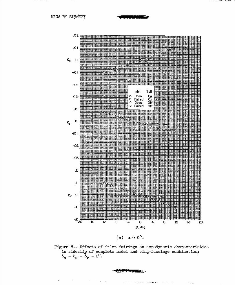
(a) a. ~ 0°.
Figur~ 8.- Effects of inlet fairings on aerodynamic characteristics in sideslip of complete model and wing-fuselage combination; 5 ~ 5 ~ 5 ~ 0°. a e r

NACA ffi.l SL56H27 tOt" 'W"Ii" 'tH
.02
.01
-Co 0
~Ol
-.02
.01
<; 0
-.01
.I
/3,deg
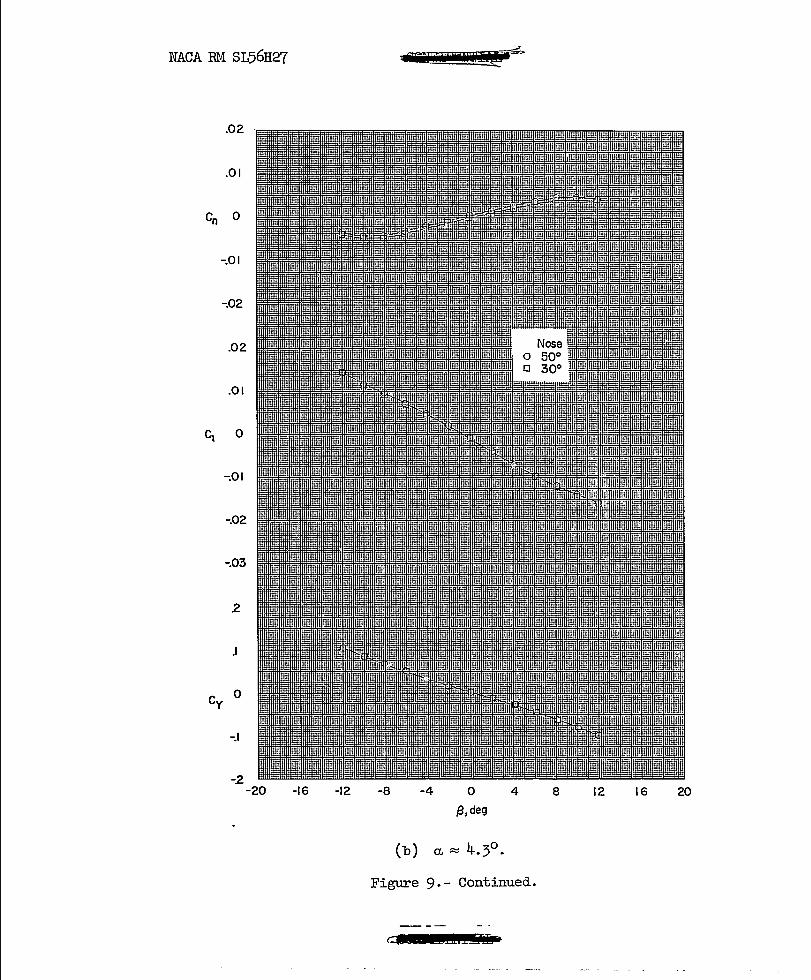
(b) a. ~ 4.3°.
Figure 8.- Continued.
~ 180Li i Ii i i4 S
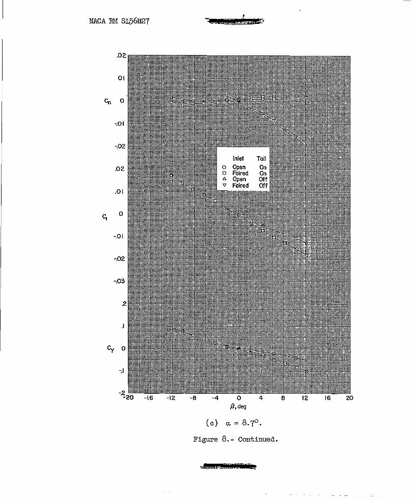
NACA RM SL56H27
.02
01
Cn 0
-.01
-.02
.02
.01
o
-:01
-.02
-.03
2
.I
Cy 0
-.\
-16 -12 -8 -4
Inlet
o /3,deg
4
Figure 8 . .;. Continued.
Ad EMIr' k::
8 12 16 20

NACA RM SL56H27 b
.02
.01
Co 0
-.01
-.02
.01
<; 0
-.01
2
J
eyo
-.\
-16 -12 -8 -4 0 4 8 12 16 20 {3,deg
(d) a. ~ 13°.
Figure 8.- Continued •
• i1 T I'M

NACA EM SL56H27 . ·s;;: 2& 4
.02
.01
Co 0
-.01
-.02 Inlet Tail
.02
.01
C; 0
-.01
-.02
-.03
2
.I
Cy 0
-.I
-~20 -16 -12 -8 -4 0 4 8 12 16 20
/3, deg
(e) a. ~ 15.2°.
Figure 8.- Concluded.
eSSE .•

NACA Rt.f SL56H27
.02
.01
Co 0
-.01
-.02
.02
.01
C; 0
-.01
-.02
-.03
2
.I
er O
-.I
:-2 -20 -16 -12 -8
- -. -- -- - . -~. -
-4
-- - --
o /3, deg
4 8 12 16 20
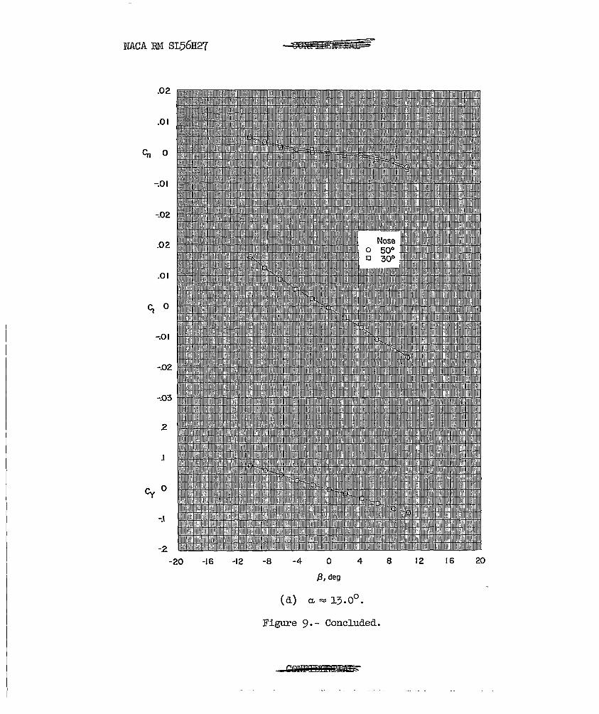
Figure 9.- Effects of fuselage nose shape on aerodynamic characteristics in sideslip of various angles of attack; complete model, o = 0 = 0 = 0°. ~ e r
NACA RM SL56H27
.02
.01
Cn 0
-.01
-.02
.02
.01
C; 0
-.01
-.02
-.03
2
.I
o Cy
-.I
-2 -20 -16 -12
fOB'? lit! 'iliJik1! ~
-8 -4 o {3, deg
4
Figure 9. - Continued.
c$ Ei±£iL
8 12 16 20

NACA RM SL56H27
.02
.01
Co 0
-.01
-.02
.02
.01
C; 0
-.01
-.02
-.03
2
.I
Cy 0
-.I
-2 -20 -16 -12 -8 -4 o
{3,aeg
4
Figure 9.- Continued.
8 12 16 20
NACA RM SL56H27
.02
.01
Co 0
-:.01
~02
.02
.01
C; 0
-.01
-.02
-.03
2
.I
eyO
-.1
-2
-20 -16 -12 -8 -4 0 4 8 12 16 20
f3, deg
(d) CL ~ 13.0°.
Figure 9. - Concluded.

t » t
NACA RM SL56H27
.18
.16
.14
.12
.10 C I 0
.08
.06
.04
.02
0
a,deg
~ -3 -2 -J o 2 3 A .5 .6 ]
Ct-
( a) Plot of Cm' CD I, and a. against. CL•
Figure 10.- Effects of rudder deflection on aerodynamic characteristics in pitch; complete model, oa = oe = 0°, ~ = 0°.
~l! !« WItE\%:

• • • •
• • • • I.
NACA RM SL56H27
o
-.01
.01
o
-.01
.I
Cy 0
-.I -8 -4 o 4 8
a"deg
8 r , deg o 0 o 9.7 <) 20
12
Figure 10.- Concluded.
16 20

NACA RM SL56H27
.02
.01
Co 0
-.01
-.02
.02
.01
C; 0
-.01
-.02
2
.I
Cy 0
-.I
-2 -20 -16 -12 -8 -4 o
/3. deg
4 8 12 16 20
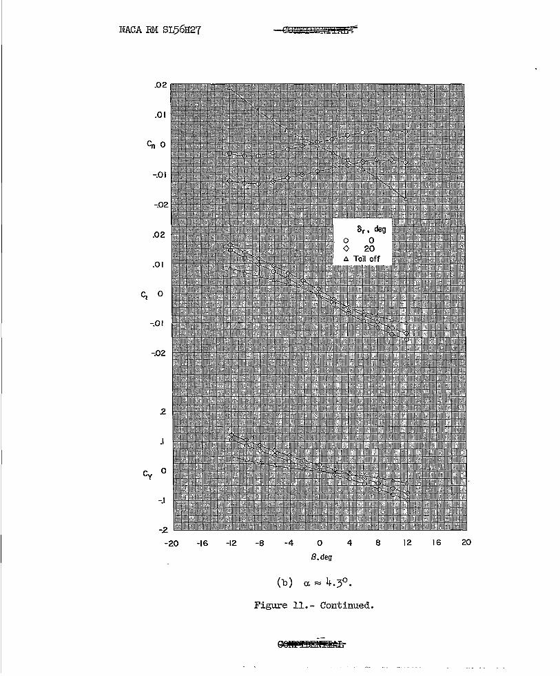
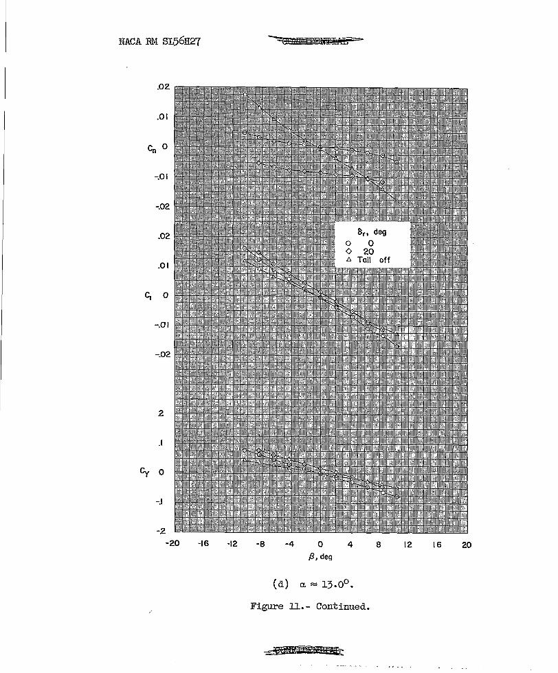
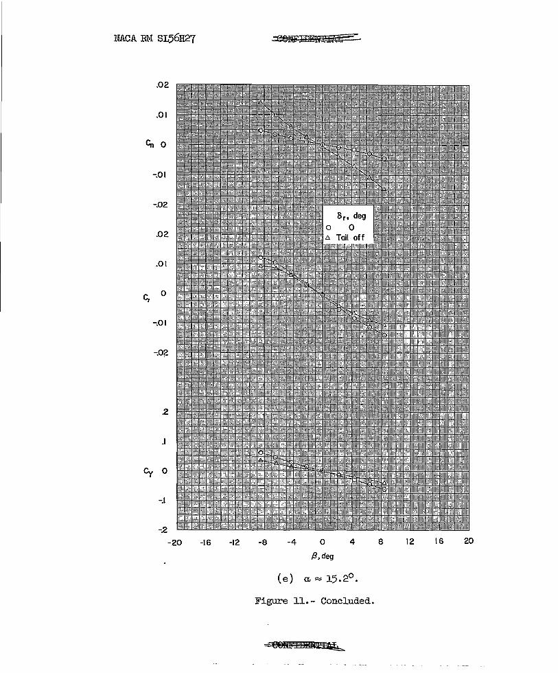
Figure ll.- Aerodynamic characteristics in sideslip at several angles of attack of complete model with various rudder deflections of \'Tingfuselage combination; oa = oe = 0 0 •
eSIWI!9!Kli!J;£ L
NACA RM SL56H27
.02
.01
<;'0
-.01
-.02
.02
.01
<1 0
-.01
-.02
2
.I
Cy 0
-.I
-2
-20 -16 -12 -8
-QIJ£!l'iIUii£lTIA£~
-4 o 4
B.deg
Figure 11.- Continued.
8 12 16 20

NACA RM SL56H27
.01
Cn 0
-.01
-.02
.02
.01
C, b
-.01
-.02
.2
.I
eyO
-.\
-.2 -20 -16 -12 -8 -4 o
p, deg
4
(c) a. ~ 8.7°.
Figure ll.- Continued.
8 12 16 20
NACA EM SL56H27
.02
.01
Cn 0
-.01
-.02
.02
.01
C; 0
-.01
-.02
2
.I
Cy 0
-.I
-2
-20 -16 -12
--=t!' liWTFT!ffiI£ar=-
-8 -4 o f3, deg
4
Figure ll.- Continued.
~eMR I I bEdittt&tt
8 12 16 20
NACA RM SL56H27
.02
.01
Co 0
-.01
-.02
.02
.01
C, 0
-.01
-.02
2
J
Cy 0
-.I
-2
-20 -16 -12 -8
~1'¥£1~
-4 o /3, deg
4
( e ) a. ~ 15. 2° •
Figure 11.- Concluded.
-'-':@@ltt :t:m!ff£llJlib,.
8 12 16 20

"" ....
.1 0
Cl A
v
-.I
-.2
-.3
-16 -12
ItlS':'" r, deg
0 9.7 '20
-8 -4 o 4 {3, deg
8 12 16
Figure 12.- Rudder hinge-moment characteristics in sideslip at several angles of attack; oe = oa = 0°,

.1 q
<> Ch r 0
-.1
-.2
-.3
-16 -12
8 y , de~
0 20
-8 -4 o {3, deg
Figure 12.- Continued.
W Q :x>
~ (/)
tri ~
.....:j
4 8 12 16

.1
o
-I .
-.2
-.3
lin n~~ UH nn Hi! ;:~: Iml I I 1111111 IiiI' H!11111i I!F 'I" '11' II" ... , , I I II I i ,I I Iii! hi! I:i: i:H in! nn in: 1m iiii lii[ iiii ni! iW Eli 8r , deg !Hi ,I, HI. !! ! ill! !iii li:i Wi iii Wi gi1 Wi if;! ;;g g~; HH
IiiI'll ',liP IPI lili HllllP Iii' il!i in! IIlllnii III III liP IIj, a 0 • I.. 1:: I !: ~ t • t: I:.:
!l·I!HHIHP ll/l !!Iilli!\ ,. ot, ,,!It • <> 20 i! ' !!!III1!!I! II!lilllii I IilH III "'1 !II' IIl'lI iI!!HIIII nil 'J I ,:;1: : nii
,1Iill! 1 I i j II WI 1m I, I ,11I1I'1l! I 'I 'llMlmH . I I ': I :i I I
: nil i I i I', n I.!!H iill Iii! lil, 1111 I III , I 'Ill!! I , I j I I Iii, 1111 ,
I II II ill I I ! . !I'LIII
! I .I i ..
,: I " I . I H !: d 11 " , HI !. Ii II! I I
I: , I I i II I
, I
1,1 'i! !:1.1 1'1 I i t
iii' 'jl! r!lli ! ~ liN If:
Ill' .,. i::! Ii rill .t I! 111 iTIl It' f Ti 'I' ! :! 1!l!llfH'I!lI I' ,J' I
I 1I ii ill! it'iii I~ ill I ,II 11 i II , III I I j' !J "
I t "Ii i 111l!11 in! TI i Ii!!l !ii,11lI II! ' ..... I
'nFlHlillUi HI III
-16 -12 -8
ilil I I I Ij II ill' Hi! iii! ill! Hii !HI iii J. j 1.1
.II. I !II! !!l!lITli TIT! : Ui1 riJi nn Iii! iig illl ,
III. II! I I II! I :lli Ii/l'!l! ::1 ,: , Illd!P' I iii! iill i1!! ! :1
iiii Ii! !!l1 ! !, iI' !w.mIHrI '1! ill. n!lllili I I I i III ,! liiii iiii,llH !P'I iI I;Wr.;,! ',,1' lilll!!1 iI I I
I
I I i II
, II
! 11 II I
.
1 I
II I.
-4
it I II l. 'III' iii I I
I I I
i I! : , . I: i , 1/
" I
I Ii !
I . i , j'l I , I
I
o f3, deg
I
:1 I
i
I
I" I iI!li! Iii! WI ' I I ! I! i Iilii It! !1l: I !i!i I' i! I,' II, I i! II HI! I I Ill! III 11 iii! i.
I ,I II I j, II' d! I iHBnH!ii!h. II ' , I I IU! I I I' illl Ihi nil III I. 1, ...... 1 ..
II I Ilil:!! . 'W ill I ,
i'
I I .1' ! llili I i I i I I , I Ii II 1'1 III di! . I I. .1'
11'1' ,!! Ill! !l ill! III !1I1 , , Ill! I ,
i :! III i jluji iili !Iii i·il ill' i 1 •• 1 .... I. I" , I I Iill IIlI iiil llii i: t I
II l!illlli :H I , ',. 1111 d I r .
! I i iii ,
i I 11'1 :iI :
, !
I. fll! .1: 1 .
1 I' , ,
I I: ! I II I , I
I
;.Ii I .1 1
.llI
4 8 12 16
Figure 12.- Continued.

(") ::r ~
I I t;J N - 0 . -
-I -m =
I = -l\) 00
I
I-:I:j CD O?
~
1-'" NO ~
~ 0 a. .......... (1)
CD p.. I 10 '-'" ~ I-'
f\) ~ .
I
a II 'n:> g I-' ...
\.)I
~ 0 () . lj 0 CD 0 p.. \0 CD p.. .
~

NACA EM SL56H27 1JQffF IIII
. 'i i
',Ii II ""11 I ,I
"I II
"II 'II' Ii Ii II iii I'll
! I'i " , , ,
,I
i,I "~"~I, ,~~;
~~~~fIEE~~~~~~'~'~~~~'~II~'~~"~:I~:~' ~il' 20
illl Ii I ! II I I', Ii I, I II I
:'1 I: I' :. I .18
I,::! ""'1:':11':'::' :~': ""'&1"': ",I ,171-,..16
~itij:l±Eti:a±1}t±~t±ili±~Eill~~' ,~' ~', , II', ',' , r;,lil I I r; , I , "t Ii' I
, ,: ': , .14
i I
[I! , 'I
I 'Ii .12 ii , ,
I , II I' I i 'II I 'I I
I !
I I I 'I .10
',_' : ';":J!1!:+!:,.J; iH-T,I±,lH' Hr'if"t+Mfli:I IJ !!: i I, Iii iii 1
11•08
i' : I I I i I" I
II , ,
, , I II I
, I !
.04 I I I i
I
II: I:: .02
.~~mttt+tI:' ~' I $I',' ~t~ 0
, ,
2 .3 .5 .6 1
( a) Plot of' Cm' Cn', and ~ against CLo
CO
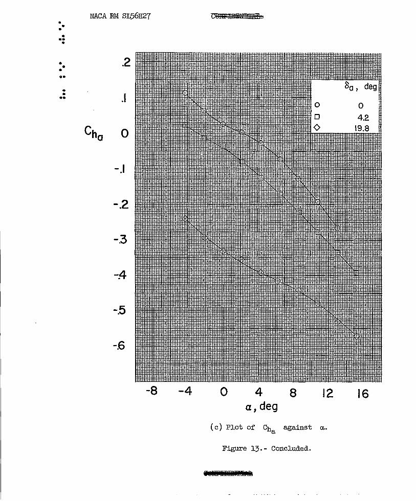
Figure 13.- Ef'f'ects of' aileron def'lection on aerodynamic characteristics in pitch; complete model, De = Or = 0°, ~ = 0°.
~Ji9iiMiif~ .~

• • • •
I
• I
I.
• • II>
NACA RM SL56H27
Cn 0
-.01
.0 I
C; 0
-.01
.I
Cy 0
-I ·-8 -4 o
.,..:;{1fT." D ~
80 , deg 0 0 0 4.2 <> 19.8
4 8 12 a,deg
(b) Plot of Cn' C2' and Cy against ~.
Figure 13.- Continued.
16 20
• • • • •• •
• • •
• • ••
NACA RM SL56H27
.I
o
-.I
-.2
-.3
-;4
-.5
-.6
-8 -4
TIOm Bi!U'f I 'j3b
0 4 8 a,deg
(c) Plot of Ch a against
Figure 13.- Concluded.
r ~ __ ~ - _. 0"-
_.. - -- ---
o o o
12
a..
80 J deg
o 4.2
19.8
16
••
• I •
. • •
• • •
• NACA RM SL56H27
.02
.OJ
Cn 0
-.OJ
-.02
.02
.OJ
'1 0
-.e)J
-.02
-.03
2
.I
Cy 0
-./
-16 -/2 -8 -4 o /3, deg
4 20 /2 8
/6
Figure 24._ E~ect of aileron deflection on aerodYnamic characteristics in sideslip for various angles of attack; 8
e _ 8r _ 00.
~-. - ---
••• • • • ••• •
•• • •• ••• • •
• » • ••
NACA RM SL56H27
.04
Crn 0
c ' o
-.04
.06
.04
.02
o
.4
.2
o
•
-12 .... 8
Guiff'HiirVPiF "ff
-4 o f3, deg
(b) Concluded.
4
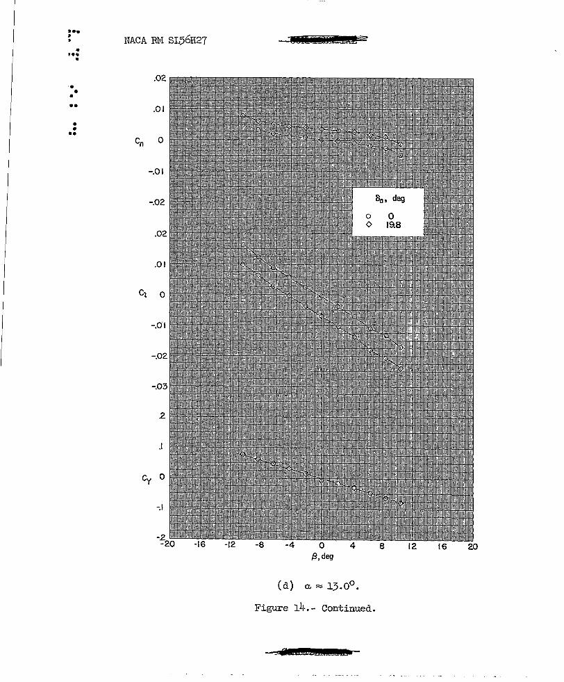
Figure 14.- Continued.
8 12 16 20

••• • • • ••• •
•• • •• ••• t •
• ) . ••
NACA RM SL56H27
.02
.01
Co 0
-.01
-.02
.02
.01
~ o·
-.01
-.02
-.03
.I
Cy 0
-.I
-2 -20
20 -16 -12 -8 -4 0
/3, deg 4 8 12 16
Figure 14.- Continued •
• UfIZMd!£d:-
.e. NACA RM SL56H27 V27TT • • e
.ee e
0 .e • ••
I ••
• -.04 I
• em • • •• -.08
-.12
.10
.08
,Co .06
.04
(c) Concluded.
Figure 14.- Continued.
@&U£M!IIL&

NACA RM SL56H27
.02'
.01
-.01
-.02
.02
.01
<; 0
-.d,1
-.02
-.03
2
.I
Cy 0
-.I
-2 -20 -16 -12 -8 -4 o
{3, deg 4
Figure l4.- Continued.
8 12 16 20

••• • • • ••• •
•• • •• ••• t t
• t • ••
NACA RM SL56H27
.04
em 0
c' o
-.04
.06
.04
.02
o
.4
.2
o
-12
Wi!l'IDirwa r 1ff
-4 o {3, deg
(b) Concluded.
4
Figure 14.- Continued.
8 12 16 20
••• • • • ••• •
•• • ,. , .. , ,
• , . ••
NACA RM SL56H27
.02
.01
Cn 0
-.01
-.02
.02
.01
<; 0
-.01
-.02
-.03
.I
Cy 0
-.I
-.2 -20 -16 -12 -8 -4 0 4 8 12 16 20
{3, deg
Figure 14. - Continued.
I •• t
NACA RM SL56H27 • --~
• t ••
•
.02 ' . • • •• .01
• • •• Cn 0
-.01
-.02
.02
.01
Cl 0
-.0' I
.I
-.\
-16 -12 -8 -4 0 4 8 12 16 20 $,deg
Figure 14.- Continued.
-::0 f 12E!&Sb

•• NACA RH SL56H27 ••• s ---• •• •
• • • I.
• Cm, • ,.
.I
C ' I D .
-12 -8 -4 0 4 8 12 16 20 f3, deg
(d) Concluded.
Figure l4.- Continued.
R IlI'll.i±£~

/ .. I I
• I ••
•
• • • ••
• • ••
NACA EM SL56H27
.02
.01
Co 0
-.01
.01
C; 0
-.01
.I
-.I
-16 -12 -8
,Wft'I!,i!!IW·gs-
-4 0 4 f3,deg
Figure 14.- Continued.
i81l iii. "
8 12 16 20

' .. • •• •
• • • ••
• • ••
NACA RM SL56H27
em
c ' D
-.04
~08
-.12
-.16
6 , r 5>
f3, deg
(e) Concluded.
Figure 14.- Concluded.
_if fEDEilLS
Cho
.I
0
-.I
-.3
-A
-.5
-16 -12 -8
0
0
-4 0 4 f3, deg
80 , deg
0
19.8
8 12 16
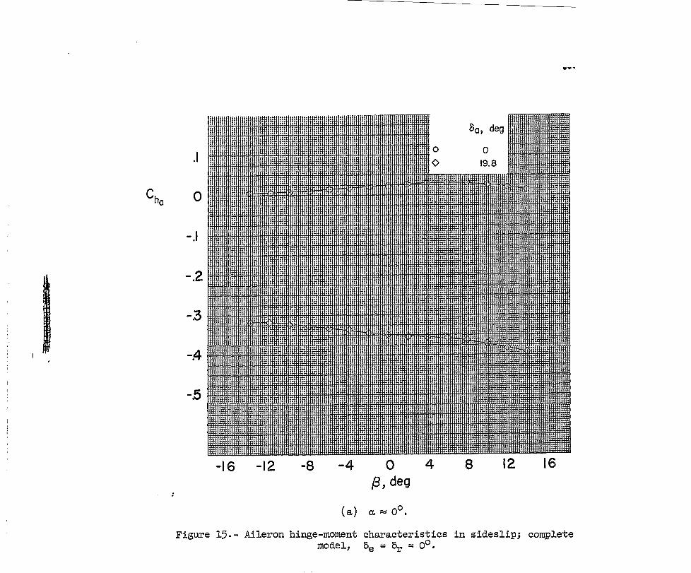
Figure 15.- Aileron hinge-moment characteristics in sideslip; complete model, Be = Br = 0°.

-.2
-.3
-.4
-.5
-16 -12 -8 -4 o /31 deg
4
Figure 15.- Continued.
8 12 16

!! 11!!llll!!mi!lHHmllllmr~llili
o i!
80 , deg
0 0 <0 /9.8
-.I
-.2
:;
-!4
-.5
-.6
-16 -12 -8 -4 0 4 8 12 {31 deg
(c) CL ~ 8.7°,
Figure 15.- Continued.
11m mn I ..
16
j j j j j j j
j j j j j
j j
j j j
I
j

0
-./
-.2
Cho -.3
-~
-.5
-.6
-:7
-16 -12 -8 -4 o f3, deg
4
'F'iaU're 1'1. - (1ont1 nllF!C'l.
80 ,
8
deg
0 19.8
12 16

o
-.5
-.6
-.7
-16 -12 -8 -4 o {3, deg
4
Figure 15.- Concluded.
8 12 16
•• • •• • ••• •
•• • •• ••• • •
• • • ••
NACA BM SL56H27
.\0
08
06
.04
-02
-04
-06
-08
-:10 -12
[
-8 -4
iiJ£!i?
o {3, deg
a, deg
0 0 0 4.3 0 8.7 ~ 13.0 Il:. 15.2
4 8 12 16
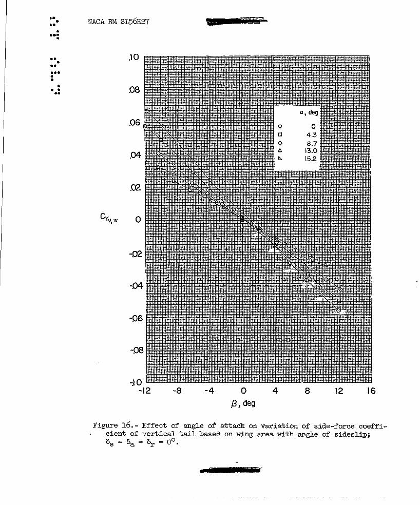
Figure 16.- Effect of angle of attack on variation of side-force coefficient of vertical tail based on i-ring area i'lith angle of sideslip; ~-~_s::.-Oo ' ve - va - vr - •
.. ... Z ___ iiiliir

, .. • t·· •
•• • •• ••• • •
• • • ••
NACA RM SL56H27 f2
.10
.08
06
.02
-02
-.04
-06
-8 -4
g -)
o /3, deg
0
0
4
8 r ,
0 9.7 20
8 12
Figure 17.- Effect of rudder deflection on variation of side-force coefficient of vert.ical tail based on \dng area with angle of sideslip for various angles of attack.
16

••• • ••• •
•• • •• ••• • •
, . • • ••
NACA RM SL56H27
.08
.06
.02
-02
-04
-06 -12 -8 -4
'iii. ..
o /3, deg
4
o
<>
Figure l7.- Continued.
~e>£DWi& r
o 20
8 12 16
j
j
j
j
j
j
j
j
j
j
j
j
j
j
j
j
j
j
j
j
j
j
j
j
j
j
j
j
j
j
j
j
j
j
j I

. •••
• •••• •
•• , . •• , ... • ,. , . • • ••
NACA EM SL56H27
.08
06
.04
.02
-02
-04
-06 -12
JI?? SPIr--
o
-8 -4 o 4 /3, deg
Figure 17.- Continued.
o 20
8 12 16
••• NACA RM SL56H27 • ••• •
•• • •• ••• • •
• .10 • • ••
06
.04
.02
c Yvw I o
-02
-04
-8
11
-4
it
o f3, deg
0
<>
4
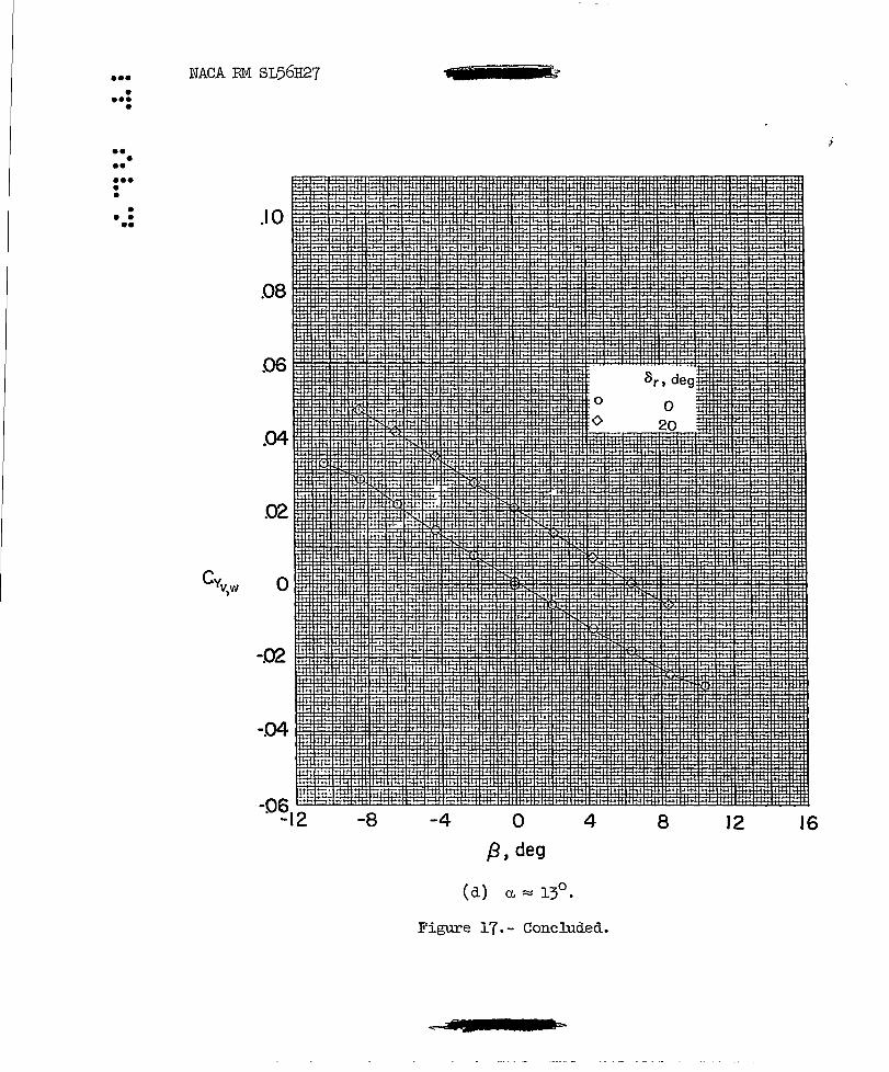
Figure 17.- Concluded.
is
SrI deg
0
8 12 16

•• • •• • ••• •
•• • •• ••• • •
• • • ••
NACA RM SL56H27
.3
.2
.I
-.I
-.2
-.3
-.4
-.5 -16 -12 -8 -4
0
0
¢ 6.
~
o S,deg
a, deg
0 4.3 8.7
13.0 15.2
4 8 12
Figure 18.- Effect of angle of attack on variation of root-bending-moment coefficient of vertical tail with angle of sideslip; 0e = 0a = or = 0°.
7

NACA RM SL56H27
.3
.2
.I
-.I
-.2
-.3 -12 -8 -4
--
o {3, deg
8 r , deg
0 0 0 9.7 0 20
4 8 12 16
Figure 19.- Effect of rudder deflection on variation of root-bendingmoment coefficient of vertical tail with angle of sideslip for various angles of attack.
all,

NACA RM SL56H27
.3
.2
.I
-.I
-.2
-8
8ml
-4 o {3, deg
0
<>
8r , deg
0 20
4
Figure 19. - Continued.
r il
12 16

• • •
NACA RM SL56H27
.3 8r , deg
.2
.I
-.I
-.2
-8 -4 o j3, deg
o 0 o 20
4
Figure 19.- Continued.
~? iih.
8 12 16

• • • •
NACA RM SL56H27
.. 3
.2
.I
-.I
-.2
-8
•
-4
IS
o f3, deg
4
o o
Figure 19.- Concluded.
G 5 .-a.
8r • deg
o
8 12 16
•• • •• • • • ••
•• • •• ••• • •
• • • ••
NACA EM SL56H27 'i ::::>
.6
S
A
.3
2
.I
Cnv 0
-.I
-2
-.3
-A
-.5
-.6
-20 -\6 -\2 -8 -4 o 4 8 12 16 20
,8.deg
Figure 20.- E~~ect o~ angle of attack on variation of yaiv.ing-moment coefficient of vertical tail I·Ti th angle of sideslip; 0e = 0a = or = 00 •

• • •
NACA ffi.l SL56H27
. 6
5
2
.I
cn,. 0
-.\
-2
-3
-~
-.5
-.6
-.7
-.8
-.9 -20
• •
-16 -12 -8 -4 o fJ,deg
4 8 12 16 20
Figure 21. - Effect of rudder deflection on variation of ya't.ring-moment coefficient of vertical tail 'td th angle of sideslip for various angles of attack.
2

NACA RM SL56H27 • R 5
. 6
5 • • • .4
.3
2
.1
0
Cnv
-.I
-.2
-3
-A-
-.5
-.6
-.7
-.8
f3. deg
Figure 21. - Continued •
.. &
NACA RM SL56H27 •
.2
.I
en" 0
-.\
-.2
-;3
-A
-.5
-.6
f3. deg
(c) a.::::: 8.7°.
Figure 21.- Continued.
t • •
NACA RM SL56H27
5
.4
,3
2
.1
o
Cnv -.\
-.2
-.3
-.5 -12
o
-8
o 20
-4 o 4
{3, deg
Figure 2l.- Concluded.
2 I £I 5
8 12. 16

t • • • •• • • • • ••
•• • • • •• •••• • , .. ). . • • t ••
NACA RM SL56H27
L o
a, deg
" &
6
4
2
12
8
.I.
Ii £
.3
o
10
.12
.08
.04
o
.4
c ' o
Figure 22.- Trim longitudinal characterist~cs; complete model, open inlets (uncorrected drag) •
. 7
·6
.5
.4
.2
.1
o
-36 -32 -28 -24 -20 -16 -12 -8 -4 o
• •••
a,deg
o 8
Figure 23. - Variation of elevator hinge-moment coefficient w'i th elevator deflection; ~ = 0°.

•••• • •••• •• • , .. • ••
• •• I. • • •• •••• • , ...
•• • , .. • ••
NACA RM SL56H27
.08
.07
.06
I1C / o D4
02
01
o o D4 08 .12
C a L
.16 .20 24
Figure 24.- Characteristics of drag due to lift; complete model, open inlets, 0e =: 0a =: Or =: 00 (uncorrected drag).

•• • • I. • t. • • • t ••
t •• • • • •• •••• • •••
•• • • • • ••
NACA RM SL56H27 • 0 a
.001
en u Inlet Tail f3
UIICU On -upen On
.001 ~ Inlet Tail
!...UIICU Off -upen Off
-()()?
.001
a Inlet TaJI
n Off ~t'- On
Cy f3
.01
.0~4 a 4 8 12 16 20 24
a, deg
Figure 25.- Variation of lateral "and directional stability characteristics for open and faired inlets for complete model and ~fing-fuselage combination; 0a = oe = Or = 0°.
&
•• • • •••• I. • • • • ••
I •• • • I ••
•••• • ~ .. •• • • • • ••
NACA RM SL56H27 z P Ed &
01
-.01
.01
-.01
o
-J
-.2
-.3 -4 16 20 24 4 8 12 o
8r • deg
Figure 26. - Variation of rudder control characteristics I'lith rudder deflection; ~ = 0°.
.. Q1£

••• • • • ••
•• • •• ••• • •
• • • ••
NACA RM SL56H27 - I aLE .
.01
en 0
-01
-.01
.1
o
-.\
Ct,o -.2
-.3
-4 . -4 o 4 8 12 16 20 24
80 , deg
Figure 27.- Variation of' aileron control characteristics Hith aileron def'lection; ~ = 0°.
$ F
•• • • •• • • • • ••
, .. • • , .. •••• • , .. I. . • •
I ••
NACA RM SL56H27 dTP •
-.001
o
o
-.01
o
-4 o 4 8 12 16 20 a.,deg
Figure 28.- Effects of angle of attack on aileron and rudder control characteristics; ~ = 00.
Q$ T
•• Q
• ••• l ,
NACA EM SL56H27
Subject
Stability, Longitudinal - Static Stability, Lateral - Static Stability, Directional - Static Control, Longitudinal Control, Lateral Control, Directional Control, Hinge Moments Loads, Steady - Tail
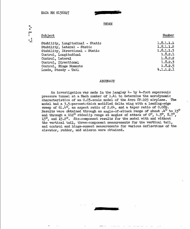
INDEX
ABSTRACT
Number
1.8.1.1.1 1.8.1.1.2 1.8.1.1.3
1.8.2.1 1.8.2.2 1.8.2.3 1.8.2.5
4.1.1.2.1
An investigation was made in the Langley 4- by 4-foot supersonic pressure tunnel at a Mach number of 1.41 to determine the aerodynamic characteristics of an 0.03-scale model of the Avro CF-105 airplane. The model had a 3.5-percent-thick modified delta wing vdth a leading-edge svTeep of 61. 40 , an aspect ratio of 2.04, and a taper ratio of 0.089. Results \'I'ere obtained through an angle-of-attack range of about -40 to 150
and through a ±120 sideslip range at angles of attack of 00, 4.30
, 8.70,
130 , and 15.20 • Six-component results for the model with and without the vertical tail, three-component measurements for the vertical tail, and control and hinge-moment measurements for various deflections of the elevator, rudder, and aileron \'Tere obtained.

\\ \\W\~\ \\\\ \~m\~\~{~\~\m\\~\\\W\\\ \ \ \\\\\\ \\\\\ 3 1176014385034.
~_ ~~"'~_~_r ____ ~___ -"- -~ , ... ,- ..... --~ .. --..,.~- " - -~'"""-~ ,,~--."-~----- ----