Embed Size (px)
Citation preview
Munters Corporation4215 Legion Dr. Mason, MI 48854-1036 USA(517) 676-7070 Fax (517) 676-7078www.munters.us/aerotech
FORM: QM1059Rev. 4, March 2010
Page 1 of 14
AX36T, AX365T, AX481T, AX4815T AX511T, AX5115T, GB36T, GB365T,
GB481T, GB4815T
Apex and Grower Tilt Fans with Galvanized Cones
aerotechR
Ventilation Systems
R

FORM: QM1059Rev. 4, March 2010
Page 2 of 14
Munters Corporation4215 Legion Dr. Mason, MI 48854-1036 USA(517) 676-7070 Fax (517) 676-7078www.munters.us/aerotech
To achieve maximum performance and insure long life from your Aerotech Fan it is essential that it be installed and maintained properly. Please read all instructions carefully before beginning installation.
Thank you for purchasing an Aerotech, Apex and Grower fan. Aerotech equipment is designed to be the highest performing, highest quality equipment you can buy. With the proper installation and maintenance it will provide many years of service.
Section
TABLE OF CONTENTS
ThANk YOu
PLEASE NOTE
Unpacking the Equipment ........................................................................................................3
Fan Dimensions........................................................................................................................3
Installation .............................................................................................................................. 4-6
Electrical Wiring ........................................................................................................................7
Operation ..................................................................................................................................8
Maintenance .......................................................................................................................... 9-10
Winterizing ...............................................................................................................................10
Troubleshooting ....................................................................................................................... 11
Exploded View ...................................................................................................................... 12-14
Page
WARRANTY
For Warranty claims information see the "Warranty Claims and Return Policy" form QM1021 available from the Aerotech Ventilation System, Munters Corporation office at 1-800-227-2376 or by e-mail at [email protected].
Conditions and Limitations:
• Products and Systems involved in a warranty claim under the "Warranty Claims and Return Policy" shall have been properly installed, maintained and operated under competent supervision, according to the instructions provided by Aerotech Ventilation Systems, Munters Corporation.
• Malfunction or failure resulting from misuse, abuse, negligence, alteration, accident or lack of proper installation or maintenance shall not be considered a defect under the Warranty.

Munters Corporation4215 Legion Dr. Mason, MI 48854-1036 USA(517) 676-7070 Fax (517) 676-7078www.munters.us/aerotech
FORM: QM1059Rev. 4, March 2010
Page 3 of 14
TC-FAn SeRieS
36" fan 48" and 51" fan
F E
G Wall Opening W
all O
peni
ng
A
C
A
C Guard
F
G
A
Wal
l Ope
ning
Wal
l Ope
ning
Shu
tter
Guard
B
C 9"
CAT. NO.FAN DIA. A D E
AX, GB36TAX, GB365TAX, GB481T
AX, GB4815TAX51T
C 43" W. x 45" H. 43" W. x 45" H.
55" W. x 56¼" H.*55" W. x 56¼" H.*57" W. x 58¼" H.*
36"36"48"48"51"
F G45¼"W. x 45¾"H.45¼"W. x 45¾"H.573/16"W. x 59¼"H.573/16"W. x 59¼"H.59⅛" W. x 61¼" H.
123/16"123/16"7⅞"7⅞"73/16"
431⁄2"431⁄2"555⁄8"555⁄8"56"
44¾"44¾"57⅜"57⅜"59⅛"
463⁄8"463⁄8"4911⁄16"4911⁄16"51⅜"
195⁄16"195⁄16"21¼"21¼"27⅛"
Wall Opening(I.D., framed)B
6"6"---------
Front View All Fans
*Opening based on 2 x 4 framing. Opening size may change with framing. See page 3.
Before beginning installation, check the overall condition of the equipment. Remove packing materials, and examine all components for signs of shipping damage. Any shipping damage is the customer's responsibility and should be reported immediately to your freight carrier.
uNPACkING ThE EquIPmENT
Fan Specifications:Power: 120/240 VAC or 208-240/480 VACPhase: 1 or 3Hertz: 60 60
NOTE: Crate may contain Fan Accessories.
D -
Dia
met
er
D -
Dia
met
er
FAN DImENSIONS
each Fan includes:1 - Belt Drive Fan4 - Cone Sections4 - Cone Support Brackets1 - Cone Guard1 - Shutter 1 - Hardware Package as follows: HP1098 - AX/GB - 36" and 48" tilt fans[A] .... 12 - 1⁄4" x 1.5" Hex Lag Screw, ZP[B] .... 16 - 1⁄4" x 20 x 1⁄2" Flange Head Bolt, ZP[C] .... 12 -1⁄4" - 20 x 3⁄4" flange Head Bolt, ZP[D] .... 28 - 1⁄4" - 20 Hex Flange Nut, ZP[E] .... 8 - 1⁄4" - 20 x 3⁄4" TEK Screw, ZP[F] .... 3 - Shutter Retainer Clips, AL HP1092 - AX - 51" tilt fans[A] .... 12 - 1⁄4" x 1.5" Hex Lag Screw, ZP[B] .... 16 - 1⁄4" x 20 x 1⁄2" Flange Head Bolt, ZP[D] .... 28 - 1⁄4" - 20 Hex Flange Nut, ZP[E] .... 8 - 1⁄4" - 20 x 3⁄4" TEK Screw, ZP[F] .... 3 - Shutter Retainer Clips, AL[G] .... 12 - 1⁄4" - 20 x 13⁄4" Flange Head Bolt, ZP[H] .... 12 - 3⁄4" O.D. x 1"L. Spacer
[A][B][C][D][E]
[G]
[H]
[F]
FORM: QM1059Rev. 4, March 2010
Page 4 of 14
Munters Corporation4215 Legion Dr. Mason, MI 48854-1036 USA(517) 676-7070 Fax (517) 676-7078www.munters.us/aerotech
Step 1 Construct the framed opening to correct size according to the Chart A (below) and
your fan size. See Figure 1A and Chart A. If fan and housing is to be framed into a 2 x 4 wall or concrete wall, See Figure 1A, 1B, 1C and Chart A for details. For greater than 4" wall thicknesses, See Figure 1D.
Clearance Notes:
Fan with Discharge Cone: maintain 12" minimum clearance on all sides
INSTALLATION INSTRuCTIONS
Chart A
Figure 1A
Ceiling
Framing Wal
l Ope
ning
(see
cha
rt)12
"
Wall Opening (see chart)
See Clearance Notes, upper right
COnCReTe wAll FRAMinG
Figure 1CFigure 1BTC-SeRieS
48" and 51" Fans
A - 2
x 4
Wal
l Ope
ning
A2 x 4 framing43"W. x 45"H.
55"W. x 56¼"H.57"W. x 58¼"H.
Catalog no.36T48T*51T*
Bconcrete framing44½"W. x 46½"H.55"W. x 57¾"H. 57"W. x 59¾"H.
Framing cut at 12° to match fan housing
31/2"
Figure 1DGReATeR THAn 4"
wAll THiCkneSSeS
*Housing slopes at 12° downward angle
B -
Con
cret
e W
all O
peni
ng
2 x 4
A - 2
x4 W
all O
peni
ng
Munters Corporation4215 Legion Dr. Mason, MI 48854-1036 USA(517) 676-7070 Fax (517) 676-7078www.munters.us/aerotech
FORM: QM1059Rev. 4, March 2010
Page 5 of 14
Step 3 Confirm that housing inside dimensions match those
shown in Figure 3A. Then secure housing to wall using (12) fastener [A] (provided) through holes in each mount-ing flange. The screws in the top flange must go through (3) Part [F] (provided), DO NOT fully tighten these screws to allow clips to rotate. See Figure 3B.
Step 4 Proceed to the Installation Instructions for the Discharge
Cone, Form QM1023 for 36" and 48" and QM1033 for 51" fans. Once Discharge Cone is completed, proceed to Electrical Wiring Section, before the shutter installation.
1/4" x 1.5" Lag Screws [A]
Retaining Clip [F]
Figure 3B
Cat. no.
Minimum inside Dimensions for Proper
Shutter Operation
36T48GT51GT
X42"
54½"56"
Y42"
54½"56¼"
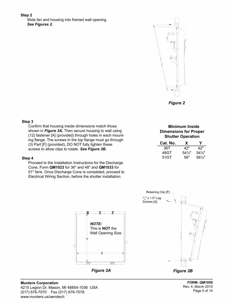
Step 2 Slide fan and housing into framed wall opening. See Figures 2.
Figure 2
NOTE:This is nOT theWall Opening Size
Y
X
Figure 3A

FORM: QM1059Rev. 4, March 2010
Page 6 of 14
Munters Corporation4215 Legion Dr. Mason, MI 48854-1036 USA(517) 676-7070 Fax (517) 676-7078www.munters.us/aerotech
Figure 4A
Step 5 Add flashing and/or caulk around completed housing on exterior
side of building wall.
Step 6 Make electrical connections to fan motor per instructions
provided with fan or as shown on motor.
Step 7 Rotate shutter retaining clips up 90°. See Figure 4A. Insert
shutter into housing and rotate shutter clips down over shutter flange to secure it in place. Pliers may be required to do this. See Figure 4B and 4C. Gently push shutter blades open by hand, checking for smooth operation. Housing installation is now complete.
Shutter Retaining Clips (rotated 90°)
Figure 4B
Figure 4C
Shutter Retaining Clips (F)
Shutter
ShuTTER INSTALLATION

Munters Corporation4215 Legion Dr. Mason, MI 48854-1036 USA(517) 676-7070 Fax (517) 676-7078www.munters.us/aerotech
FORM: QM1059Rev. 4, March 2010
Page 7 of 14
All wiring should be installed in accordance with National, State, and Local electrical codes. Fans used to ventilate livestock buildings or other rooms where continuous air movement is essential should be connected to individual electrical circuits, with a minimum of two circuits per room. For electrical connection requirements, refer to diagram on motor nameplate and to information enclosed with the Aerotech environ-mental control to be used.
Single Phase Fans: motor overload protection should be provided for each fan. A Circuit Breaker Switch or slow blow motor type fuses must be used See Figure 5. See Aerotech form QM1400 for proper size. NOTE: A safety cut-off switch should be located adjacent to each fan.
ELECTRICAL WIRING
WARNING!
ROTATING FAN BLADES. Operation of fan without wire screens or guards may result in direct contact with blades and cause severe personal injury or death.
Figure 5Single Phase - Motor Overload Protection with Disconnect
(SY2000 or equivalent)keY: L1 = Line 1 H = Hot L2 = Line 2 N = Neutral G = GroundnOTe: Information in parenthesis refers to 120 VAC control.
120 or 240 VAC Power Supply for Fan
L1 (H)
L2 (N)
G
T1 (H)
T2 (N)
G
120 or 240 VACPower Out to Fan
L1 (H)
L2 (N)
T1 (H)
T2 (N)
1) 36" Direct Drive, 3 Phase fan is not suitable for frequency drive.2) The use of a quality frequency drive and the installation of line reactors is recommended to reduce voltage spikes and harmonic distortion.3) Minimum operating frequency of 30 Hz.4) Will require three pole contactors with overload protection (by others) if a frequency drive is not used.
Three Phase Fans:
»install shutter at this time, go back to Step 7 in the installation instructions Section.
Recommended wire routing:As the power cable exits the back of motor form a drip loop and then run power cable down along strut and "zip tie" the cable to strut to prevent cable from getting tangled in the pulley or belt. See figure 6. Then run the cable out the hole to the circuit breaker or control panel.
Zip tie
Drip loop
Figure 6
FORM: QM1059Rev. 4, March 2010
Page 8 of 14
Munters Corporation4215 Legion Dr. Mason, MI 48854-1036 USA(517) 676-7070 Fax (517) 676-7078www.munters.us/aerotech
1) iniTiAl START-UP: With electrical power off, verify that the fan propeller turns freely and that all fasteners are secure. Turn on electrical power and confirm that the fan operates smoothly.
2) ADJUSTMenTS: Set the fan control to the temperature shown on your Aerotech ventilations system drawing, or to a value which will provide the desired environmental conditions.
3) BelT ADJUSTMenTS: After 3 days of operation you must tighten fan belt. See Maintenance Section: Belt Tension.
WARNING!
moving parts,disconnect power before servicing.
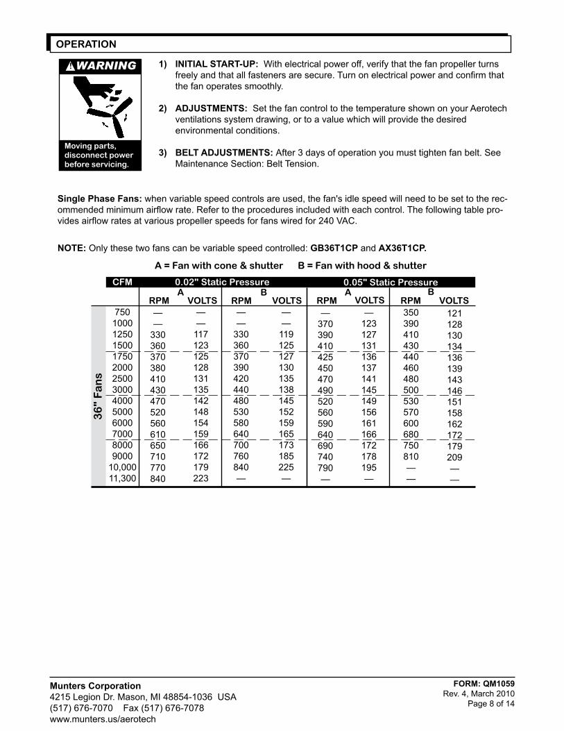
Single Phase Fans: when variable speed controls are used, the fan's idle speed will need to be set to the rec-ommended minimum airflow rate. Refer to the procedures included with each control. The following table pro-vides airflow rates at various propeller speeds for fans wired for 240 VAC.
OPERATION
7501000125015001750200025003000400050006000700080009000
10,00011,300
A = Fan with cone & shutter B = Fan with hood & shutter
36
" F
an
s
0.02" Static Pressure 0.05" Static Pressure
——
330360370390420440480530580640700760840—
RPm VOLTSA
CFm
RPm VOLTSB
——
330360370380410430470520560610650710770840
RPm VOLTSA
RPm VOLTSB
——
117123125128131135142148154159166172179223
——
119125127130135138145152159165173185225—
—370390410425450470490520560590640690740790—
350390410430440460480500530570600680750810——
121128130134136139143146151158162172179209——
—123127131136137141145149156161166172178195—
nOTe: Only these two fans can be variable speed controlled: GB36T1CP and AX36T1CP.
Munters Corporation4215 Legion Dr. Mason, MI 48854-1036 USA(517) 676-7070 Fax (517) 676-7078www.munters.us/aerotech
FORM: QM1059Rev. 4, March 2010
Page 9 of 14
The following inspection and cleaning procedures should be performed monthly:
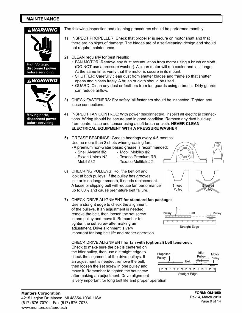
1) INSPECT PROPELLER: Check that propeller is secure on motor shaft and that there are no signs of damage. The blades are of a self-cleaning design and should not require maintenance.
2) CLEAN regularly for best results: • FAN MOTOR: Remove any dust accumulation from motor using a brush or cloth. (DO NOT use a pressure washer). A clean motor will run cooler and last longer. At the same time, verify that the motor is secure in its mount. • SHUTTER: Carefully clean dust from shutter blades and frame so that shutter opens and closes freely. A brush or cloth should be used. • GUARD: Clean any dust or feathers from fan guards using a brush. Dirty guards can reduce airflow.
3) CHECK FASTENERS: For safety, all fasteners should be inspected. Tighten any loose connections.
4) INSPECT FAN CONTROL: With power disconnected, inspect all electrical connec- tions. Wiring should be secure and in good condition. Remove any dust build-up from control case and sensor using a soft brush or cloth. neVeR CleAn eleCTRiCAl eQUiPMenT wiTH A PReSSURe wASHeR!
5) GREASE BEARINGS: Grease bearings every 4-6 months. Use no more than 2 shots when greasing fan. • A premium non-water based grease is recommended: - Shell Alvania #2 - Mobil Mobilux #2 - Exxon Unirex N2 - Texaco Premium RB - Mobil 532 - Texaco Multifak #2
WARNING!
moving parts,disconnect power before servicing.
WARNING!
high Voltage,disconnect power before servicing.
mAINTENANCE
6) CHECKING PULLEYS: Roll the belt off and look at both pulleys. If the pulley has grooves in it or is no longer smooth, it needs replacement. A loose or slipping belt will reduce fan performance up to 60% and cause premature belt failure.
7) CHECK DRIVE ALIGNMENT for standard fan package: Use a straight edge to check the alignment of the pulleys. If an adjustment is needed, remove the belt, then loosen the set screw in one pulley and move it. Remember to tighten the set screw after making an adjustment. Drive alignment is very important for long belt life and proper operation. CHECK DRIVE ALIGNMENT for fan with (optional) belt tensioner: Check to make sure the belt is centered on the idler pulley, then use a straight edge to check the alignment of the drive pulleys. If an adjustment is needed, remove the belt, then loosen the set screw in one pulley and move it. Remember to tighten the set screw after making an adjustment. Drive alignment is very important for long belt life and proper operation.
SmoothPulley
GroovedPulley
MotorPulley
Straight Edge
Belt
IdlerPulley
PropellerPulley
PulleyPulley
Straight Edge
Belt
FORM: QM1059Rev. 4, March 2010
Page 10 of 14
Munters Corporation4215 Legion Dr. Mason, MI 48854-1036 USA(517) 676-7070 Fax (517) 676-7078www.munters.us/aerotech
In most climates, it is probable that the ventilation system will never need to operate at a total capacity during the colder winter months. Consequently, it is advisable to "winterize" those fans which will not be used in cold weather to avoid unnecessary heat loss and condensation.
To winterize, turn fan control "off". Install the insulated closure panel over the fan intake. If you don't have an insulated closure panel, a piece of rigid insulation material can be used. Remember the insulation panel must be removed before warmer weather returns.
NOTE: At least one single speed fan should be left uncovered and with power available to provide air move-ment in the event of variable speed control difficulties.
WINTERIZING FAN
Alignment Mark
Hex
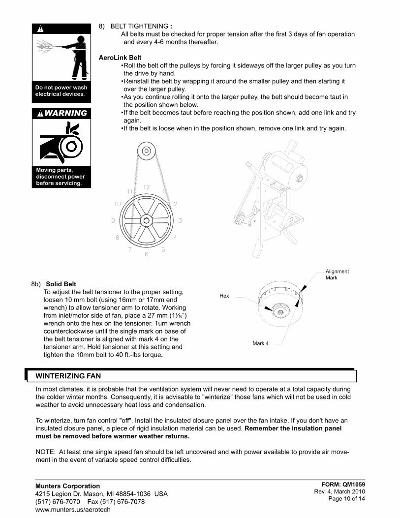
8) BELT TIGHTENING : All belts must be checked for proper tension after the first 3 days of fan operation
and every 4-6 months thereafter.
Aerolink Belt • Roll the belt off the pulleys by forcing it sideways off the larger pulley as you turn
the drive by hand. • Reinstall the belt by wrapping it around the smaller pulley and then starting it
over the larger pulley. • As you continue rolling it onto the larger pulley, the belt should become taut in
the position shown below. • If the belt becomes taut before reaching the position shown, add one link and try
again. • If the belt is loose when in the position shown, remove one link and try again.
!
Do not power wash electrical devices.
WARNING!
moving parts,disconnect power before servicing.
Mark 4
8b) Solid Belt To adjust the belt tensioner to the proper setting,
loosen 10 mm bolt (using 16mm or 17mm end wrench) to allow tensioner arm to rotate. Working from inlet/motor side of fan, place a 27 mm (11⁄16”) wrench onto the hex on the tensioner. Turn wrench counterclockwise until the single mark on base of the belt tensioner is aligned with mark 4 on the tensioner arm. Hold tensioner at this setting and tighten the 10mm bolt to 40 ft.-lbs torque.
Munters Corporation4215 Legion Dr. Mason, MI 48854-1036 USA(517) 676-7070 Fax (517) 676-7078www.munters.us/aerotech
FORM: QM1059Rev. 4, March 2010
Page 11 of 14
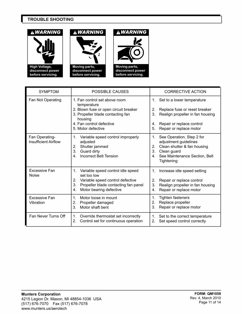
Fan Operating-Insufficient Airflow
Excessive Fan Noise
1. Fan control set above room temperature2. Blown fuse or open circuit breaker3. Propeller blade contacting fan housing4. Fan control defective5. Motor defective
1. Variable speed control improperly adjusted2. Shutter jammed3. Guard dirty4. Incorrect Belt Tension
1. Variable speed control idle speed set too low2. Variable speed control defective3. Propeller blade contacting fan panel4. Motor bearing defective
1. Set to a lower temperature
2. Replace fuse or reset breaker3. Realign propeller in fan housing
4. Repair or replace control5. Repair or replace motor
1. See Operation, Step 2 for adjustment guidelines2. Clean shutter & fan housing3. Clean guard4. See Maintenance Section, Belt Tightening
1. Increase idle speed setting
2. Repair or replace control3. Realign propeller in fan housing4. Repair or replace motor
Fan Not Operating
SYMPTOM POSSIBLE CAUSES CORRECTIVE ACTION
Excessive FanVibration
1. Motor loose in mount2. Propeller damaged3. Motor shaft bent
1. Tighten fasteners2. Replace propeller3. Repair or replace motor
Fan Never Turns Off 1. Override thermostat set incorrectly2. Control set for continuous operation
1. Set to the correct temperature2. Set speed control correctly
TROuBLE ShOOTING
WARNING!
moving parts,disconnect power before servicing.
WARNING!
high Voltage,disconnect power before servicing.
WARNING!
moving parts,disconnect power before servicing.
FOR
M: Q
M10
59R
ev. 4
, Mar
ch 2
010
Pag
e 12
of 1
4
Mun
ters
Cor
pora
tion
4215
Leg
ion
Dr.
Mas
on, M
I 488
54-1
036
US
A(5
17) 6
76-7
070
Fa
x (5
17) 6
76-7
078
ww
w.m
unte
rs.u
s/ae
rote
ch
Apex
and
Gro
wer
Fan
s w
ith G
alva
nize
d Co
nes
Munters Corporation4215 Legion Dr. Mason, MI 48854-1036 USA(517) 676-7070 Fax (517) 676-7078www.munters.us/aerotech
FORM: QM1059Rev. 4, March 2010
Page 13 of 14
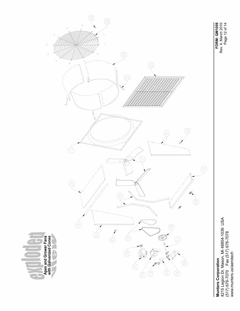
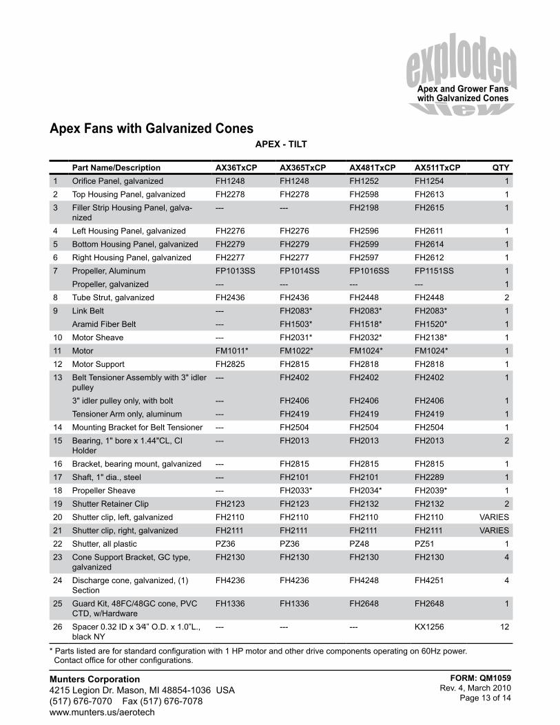
Apex and Grower Fans with Galvanized Cones
APeX - TilT
Part name/Description AX36TxCP AX365TxCP AX481TxCP AX511TxCP QTY1 Orifice Panel, galvanized FH1248 FH1248 FH1252 FH1254 12 Top Housing Panel, galvanized FH2278 FH2278 FH2598 FH2613 13 Filler Strip Housing Panel, galva-
nized--- --- FH2198 FH2615 1
4 Left Housing Panel, galvanized FH2276 FH2276 FH2596 FH2611 15 Bottom Housing Panel, galvanized FH2279 FH2279 FH2599 FH2614 16 Right Housing Panel, galvanized FH2277 FH2277 FH2597 FH2612 17 Propeller, Aluminum FP1013SS FP1014SS FP1016SS FP1151SS 1
Propeller, galvanized --- --- --- --- 18 Tube Strut, galvanized FH2436 FH2436 FH2448 FH2448 29 Link Belt --- FH2083* FH2083* FH2083* 1
Aramid Fiber Belt --- FH1503* FH1518* FH1520* 110 Motor Sheave --- FH2031* FH2032* FH2138* 111 Motor FM1011* FM1022* FM1024* FM1024* 112 Motor Support FH2825 FH2815 FH2818 FH2818 113 Belt Tensioner Assembly with 3" idler
pulley--- FH2402 FH2402 FH2402 1
3" idler pulley only, with bolt --- FH2406 FH2406 FH2406 1Tensioner Arm only, aluminum --- FH2419 FH2419 FH2419 1
14 Mounting Bracket for Belt Tensioner --- FH2504 FH2504 FH2504 115 Bearing, 1" bore x 1.44"CL, CI
Holder--- FH2013 FH2013 FH2013 2
16 Bracket, bearing mount, galvanized --- FH2815 FH2815 FH2815 117 Shaft, 1" dia., steel --- FH2101 FH2101 FH2289 118 Propeller Sheave --- FH2033* FH2034* FH2039* 119 Shutter Retainer Clip FH2123 FH2123 FH2132 FH2132 220 Shutter clip, left, galvanized FH2110 FH2110 FH2110 FH2110 VARIES21 Shutter clip, right, galvanized FH2111 FH2111 FH2111 FH2111 VARIES22 Shutter, all plastic PZ36 PZ36 PZ48 PZ51 123 Cone Support Bracket, GC type,
galvanizedFH2130 FH2130 FH2130 FH2130 4
24 Discharge cone, galvanized, (1) Section
FH4236 FH4236 FH4248 FH4251 4
25 Guard Kit, 48FC/48GC cone, PVC CTD, w/Hardware
FH1336 FH1336 FH2648 FH2648 1
26 Spacer 0.32 ID x 3⁄4” O.D. x 1.0”L., black NY
--- --- --- KX1256 12
Apex Fans with Galvanized Cones
* Parts listed are for standard configuration with 1 HP motor and other drive components operating on 60Hz power. Contact office for other configurations.
FORM: QM1059Rev. 4, March 2010
Page 14 of 14
Munters Corporation4215 Legion Dr. Mason, MI 48854-1036 USA(517) 676-7070 Fax (517) 676-7078www.munters.us/aerotech
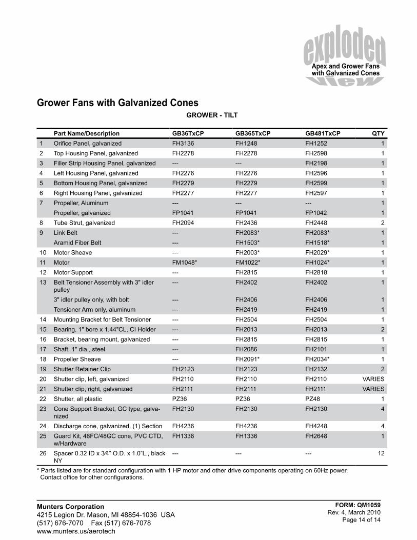
GROweR - TilT
Part name/Description GB36TxCP GB365TxCP GB481TxCP QTY1 Orifice Panel, galvanized FH3136 FH1248 FH1252 12 Top Housing Panel, galvanized FH2278 FH2278 FH2598 13 Filler Strip Housing Panel, galvanized --- --- FH2198 14 Left Housing Panel, galvanized FH2276 FH2276 FH2596 15 Bottom Housing Panel, galvanized FH2279 FH2279 FH2599 16 Right Housing Panel, galvanized FH2277 FH2277 FH2597 17 Propeller, Aluminum --- --- --- 1
Propeller, galvanized FP1041 FP1041 FP1042 18 Tube Strut, galvanized FH2094 FH2436 FH2448 29 Link Belt --- FH2083* FH2083* 1
Aramid Fiber Belt --- FH1503* FH1518* 110 Motor Sheave --- FH2003* FH2029* 111 Motor FM1048* FM1022* FH1024* 112 Motor Support --- FH2815 FH2818 113 Belt Tensioner Assembly with 3" idler
pulley--- FH2402 FH2402 1
3" idler pulley only, with bolt --- FH2406 FH2406 1Tensioner Arm only, aluminum --- FH2419 FH2419 1
14 Mounting Bracket for Belt Tensioner --- FH2504 FH2504 115 Bearing, 1" bore x 1.44"CL, CI Holder --- FH2013 FH2013 216 Bracket, bearing mount, galvanized --- FH2815 FH2815 117 Shaft, 1" dia., steel --- FH2086 FH2101 118 Propeller Sheave --- FH2091* FH2034* 119 Shutter Retainer Clip FH2123 FH2123 FH2132 220 Shutter clip, left, galvanized FH2110 FH2110 FH2110 VARIES21 Shutter clip, right, galvanized FH2111 FH2111 FH2111 VARIES22 Shutter, all plastic PZ36 PZ36 PZ48 123 Cone Support Bracket, GC type, galva-
nizedFH2130 FH2130 FH2130 4
24 Discharge cone, galvanized, (1) Section FH4236 FH4236 FH4248 425 Guard Kit, 48FC/48GC cone, PVC CTD,
w/HardwareFH1336 FH1336 FH2648 1
26 Spacer 0.32 ID x 3⁄4” O.D. x 1.0”L., black NY
--- --- --- 12
Grower Fans with Galvanized Cones
Apex and Grower Fans with Galvanized Cones
* Parts listed are for standard configuration with 1 HP motor and other drive components operating on 60Hz power. Contact office for other configurations.