Embed Size (px)
Citation preview

FAILURE OF PRESTRESSED CONCRETE BRIDGE DECK BEAMS X01 of 11016, I 94 over NYCRR
G. R. Cudney
Research Laboratory Division Office of Testing and Research
Research Project 61 B-54 Report No. 372
··-,, ,;
'.
Michigan State Highway Department John C. Mackie, Commissioner
Lansing, February 1962

FAILURE OF PRESTRESSED BRIDGE DECK BEAMS X01 of 11016, I 94 over NYCRR
This report summarizes an investigation into the cause of failure of certain prestressed box-beam girders of Bridge X01 of 11016 (formerly BIX1of 11-2-6), carrying I 94 over the New York Central railroad southeast of Benton Harbor. At various intervals during the progress of this investigation, the results of all observations have been reported in a series of letter reports.
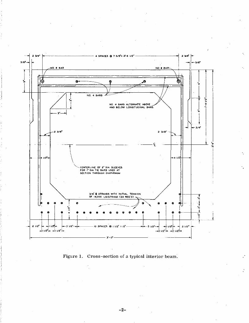
Each of the dual bridges involved consists of three 58-ft, simply supported spans on a 53° 53' skew. Each span consists of 16 prestressed, precast box-beam girders. A cross-section and a plan view of a typical interior beam are shown in Figs. 1 and 2, and identification· numbering for all 96 beams showing their specific locations is given in Fig. 3.
Earlier Investigation (September 1960)
The bridges were both opened to traffic on November 3, 1960, and the distressed beams first discovered about January 7, 1961. Before this, in September 1960, after all beams were in place on the bridges, an investigation was instigated as a result of an incident in which a construction vehicle had punched through the top walls of two beams on the northbound bridge. To ascertain the top wail thicknesses for the 84 interior beams, two 0.5-in. holes were drilled by the Field Testing Division in the top of each of the three large voids of each beam. The following variations in top thickness were reported:
Total Beams 16 22 33 13
Top Thickness 4 in. or more 3 to 4 in. 2 to 3 in. less than 2 in.
In addition, 22 holes of 8 to 10 in. diam were knocked in the tops of 22 interior beams by the beam fabricator to measure side wall thickness variation, at the locations indicated in Fig. 3, and 10 holes were drilled in the sides of 10 fascia beams for the same purpose. Side wail thickness was found to vary from 4. 25 to 5. 5 in., the average being 4. 75 in.
4 SPACES $ 7 5/8"= 2!.8 112" -------------1
NO.8 BAR--.
\ l
4
····-=:4 •• :ERNATE ABOV~ I AND BELOW LON<ITUDINAL .:.A
2 3/8"-~--
I
_,,__., .. i
·•
~t ..
J J ~3/4'
i
1---- 4 V2'-II
f.-· '"' I f----.
" " .. t ·~ .. .. i i
"'--CENTERLINE OF 2" OIA_ SLEEVES FOR I" OIA TIE BARS USED AT SECTION THROUG.H DIAPHRAG-M
..
.. •
3/8' t STRANDS WITH INITIAL TENSION Of 14,000 L8/STRANO (29 REQ'O) ~
,.- -- ---- -) ·~ 888009198.
I ! ~ t f/2'' f_ • I 1/2~ ~J l/2" 10 SPACES @ I 112" :: ~~··••-----t--3 1/211__., ..., I 112."~ 2 112"
I !df- _,j I 1/2" ~ - I l/2'' k- ..., I l/2n
--------------- 3'-0" ------------- ---
Figure 1. Cross-section of a typical interior beam.
-2-
•N , • _ _,_

I
"' I
~------------------------------------------------------------57-7V4"------------------------------------------------------------~
2'-2 ..,.. z'-z v4•
17·-,,··-----4--,.-+~-J+-i f---,--. --- ••'-• •n•---4-+~--J--+i-f _____ 20'-• ,..
gf ~~~ ~~n 111 111 --~ ,---------------,,1 rrll r------------,llr-,11 I I -~ I \Ill Jill 1111 IIlii I . I I I Ill Ill
• • 1/2. CONCRETE INSERTS II I I I I I ·~ ~ ~ ~ (%. I '~0~0~6~~ ~~.~~~M 1\11 \II i'1J\ ill I I UJ / I (TYP•CAL) IIJI II I Ill Ill I
lL I ~II H"~-----------~''H'l~---------J
/; I '
I; 2" DIA. SLEEVES FOR
I" OLA. POSITION DOWELS (TYPICAL) I · •'-w-Lj H· ~2vs" , ··-·~.· H· ~m· • ~~ b7wa• l---- 15'-1·~ ~ t4-V2" ~ 15-1· 2 ~ z'-211'4"
Figure 2. · Plan view of a typical interior beam.

I .,.. I
25'-9"1 "'"" NUMBERS
" .. " • •
. , • • . . " • " u .. " "
~ " 1 sounisouNo j ., " , " .. ~
' I I
; ;
.. ·~
.. .. ·~
"
.. ..
" • • U, ..
J ,._,.
"
M
N
"·
"
I
" I
; I
I
u
" .. .. u
" "
~~ l-r I
; I
;
If » ~
;.~ -- I _er 3 ( ~i
f· L___i_ 30 ~ fo I ~ ~
I .• ·il__ -1 f· i'· ' ' ' M ------ - j $ ~'J' uj
(NORTHBOUND 1/ 7 ' L -9 • .z ;; T 7 ~ -I•
I ;i I "I -~ T :>1 ;,; .. 7 i I ·L "I
L· I•
I· -0 ,oL L I ·'Lti .. ;
$ z __ 1 1 ~~z 1 3$7 I•
7 ;. /• I ,. I ,0 I ·o/_L ·of
I· I I~---- I 1- 'll ------;.;
L L J"_,. ""'J I. _ j'""L_ _ _j. 25-9" :as'-7'~
s7'-s~ s7'-e" . 57'-e"
~ $ 8 TO 10-IN. DIAMETER HOLES IN
BEAM TOPS f'OR SIDEWALL Tl-UCKZ-IESS MEASUREMENTS
0 HOl.ES IN BEAM TOPS CAUSED BY CONSTRUCTION VEHICLE
Figure 3. Beam identification numbering with locations of holes in beam top walls.
N
~.

First Inspection (January 1961)
On February 1, 1961, a special Departmental committee was formed for correlation and cooperation in various phases of an investigation into the causes of the deterioration noted the preceding month. Members included J. C. Brehler, C. H. Cash, R. S. Fulton, P. A. Nordgren, L. T. Oehler, and C. J. Olsen, with E. A. Finney as Chairman.
The bridges were first inspected by the Research Laboratory Division on January 31, 1961, and the following conditions were observed:
1. Extensive longitudinal and diagonal cracking on the bottom surface of the south end of Beam18 (Fig. 4). The longitudinal crack extended along the entire south third of the beam and into the end anchorage block.
2. Transverse and longitudinal cracks on the bottom surface of Beam 19 near a diaphragm and transverse tie bars (Fig. 5).
3, A pair of diagonal cracks on the bottom surface of Beam 24 near a diaphragm and transverse tie bars (Fig. 5).
4. Extensive longitudinal cracking and spalling on the bottom surface of Beam 58 near a diaphragm and transverse tie bars (Fig. 6). In addition, a transverse crack was observed above this distressed area, in the 5 to 7 in. thick concrete deck slab.
5. A longitudinal crack on the bottom surface of Beam 61 extending into the end anchorage block.
Second Inspection (February 1961)
The Research Laboratory Division's second inspection included two days of observations, February 3 and 17, 1961. On the former date, two 0. 5-in. diam holes were drilled through the bottom of Beam 58 into the large voids adjacent to what was then believed to be a solid concrete diaphragm 3 ft 4 in. long. No evidence of ice or water was found in either of these voids. Fig. 7 shows, however, that ice or water were observed here later in February, and also at the same points on Beams 18 and 19 where deterioration had been noted in the January inspection. Fig. 7 also shows ice discovered at the joint between Beams 74 and 75, once again at about the one-third point on the span near the diaphragm and transverse tie bars, although the visible surfaces of these last two beams appeared to be undamaged.
-5-

-
-6-

(
I
...._ Beam 19, Northbound 4 Beam 24, Northbound
Figure 5. Distressed beams (first inspection, January 1961).
-7-

-8-

Beam 18
Beam 58
Beam 75
-9-
Beam 19
Beam 61
Figure 7. Distressed beams (second inspection, February 1961).

Inquiry into the fabrication, transportation, and erection of the beams revealed that all were fabricated in August and September 1959, and stored outdoors in the fabricator's yard for one year prior to shipment to the bridge site. There was no relation between the dates the beams were fabricated, or their positions in the casting bed, and the locations of the distressed beams in the bridge. There was no evidence indicating poor concrete mix or strength, or unequal . pretensioning of the prestressing strands. The beams were erected directly from the transporting vehicle upon its arrival at the site. Further, there was no evidence of cracking or distress of any kind from the time the beams arrived at the site until they were in final position with the longitudinal keyways between beams grouted and sealed. Erection of the beams was completed by August 11, 1960.
The only significant factor uncovered by this inquiry was that the already noted variations in beam wall thickness were caused by floating of the void box liner forms during fabrication.
Third Inspection (March 1961)
On March 9, the special committee met again to discuss the status of the beam failures. It was decided to seal the prestressing strands to prevent corrosion, and in the process to explore further into the nature and extent of the beam failures.
A third inspection period, including observations between March 23 and Aprilll, 1961, produced the following data:
1. The longitudinal and diagonal cracks on the bottom of Beam 18 extended through the bottom wall into the beam void (Fig. 8). In addition, cracks were observed extending upward diagonally on the beam's west side into the south anchorage block, and longitudinal cracks extended into the anchorage block on the beam's east side. Chunks of ice were visible in the south end of the void, apparently having accumulated in the divider spaces of the cardboard void liner forms.
2. Loose chunks of concrete were visible on the west side of Beam 19 in the small void area, as well as a crack extending about 6 to 8 ft into the center void (Fig. 8). The transverse crack south of the diaphragm area appeared to angle back and upward toward the small void. Holes drilled into the small void between tie bars and into the south end void indicated these to be dry. A 1. 5-in. diam hole drilled into the center void adjacent to the small void, however, produced a flow of water lasting about 45 min.
-10-

I ...... ...... I
Beam 18 Beam19
Figure 8. Distressed beams (third inspection, March 1961).

3. In the distressed area bfBeam 24, there was no evidence of any water or ice in either of the two large voids or the small void. No cracks were visible on the beam's "(last side, but one was observed on the west side extending from about 2 ft into the center void through the diaphragm section and continuing about 2 ft into the end void.
4. A void about 12 in. long was discovered between the two tie bars in the diaphragm at the distressed area of Beam 58 (Fig. 9). The west side wall of this small void was fractured completely through, and the vertical stirrup reinforcement was bent outward. In addition, diagonal cracks extended from the lower inside corners of the small void down through the beam's bottom wall. The short longitudinal crack at the beam center proved to be a fracture through the bottom wall into the small void.
5. No cracking appeared either on the bottom or sides of Beam 75. However, water drained for about 1. 5 hr from a 0. 5-in. diam hole drilled in the small void, and for better than 2. 5 hr from holes of the same size drilled in the north and center large voids (Fig. 9).
In addition to the longitudinal crack previously described in Beam 61, similar short longitudinal cracks were found extending along the obtuse angle sides of Beams 53 and 96. Holes of 0. 5-in. diam drilled into the end voids of these three beams revealed no water.
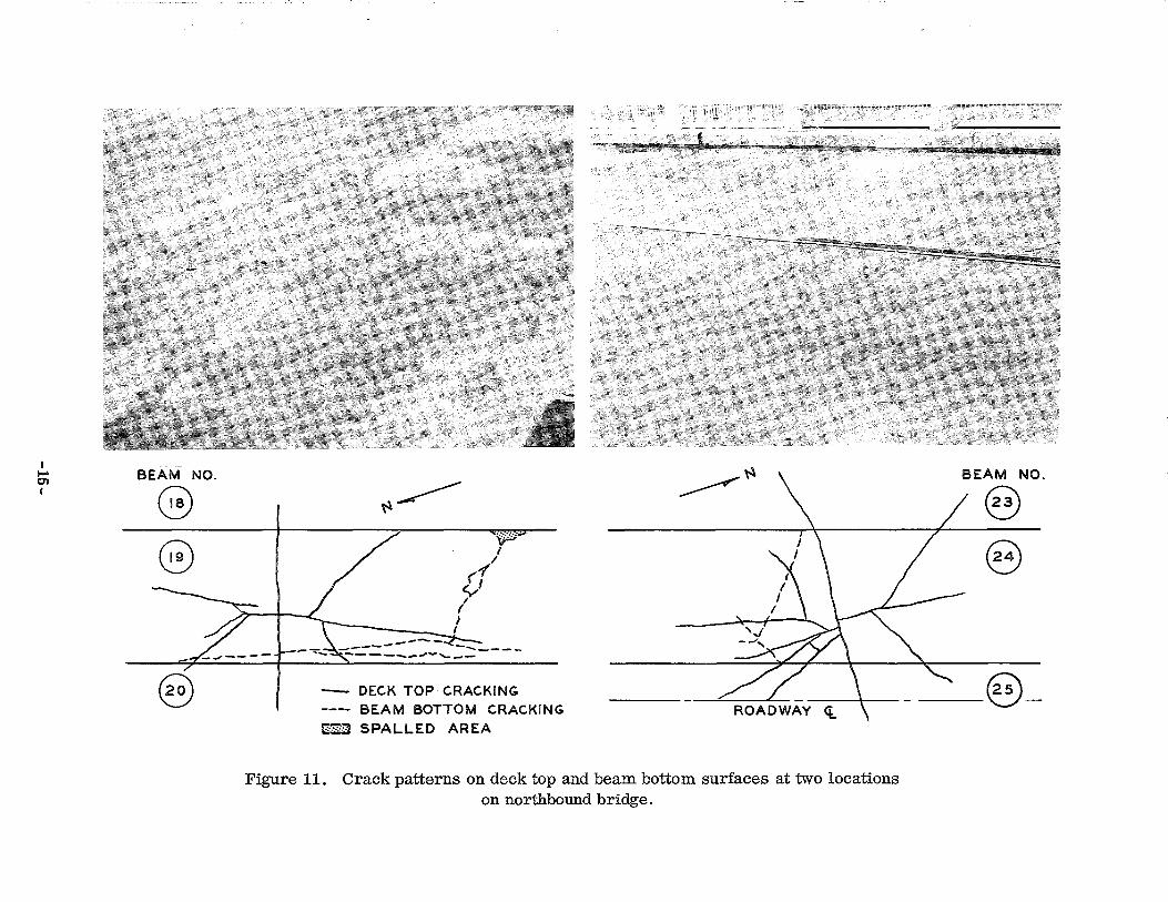
During this phase of the investigation four definite crack patterns were also established on the 5 to 7 in. thick deck slab. These cracks were located above the distressed areas of Beams 19, 24, 58, and 75, as previously described. The basic patterns at these four locations consisted essentially of a transverse and longitudinal crack with a pair of diagonal V -slope cracks on each side of the transverse crack. Photos and diagrams of each of these patterns are shown in Figs. 10 and 11, along with the relative position and condition of bottom surfaces of the corresponding distressed beams.
Discussion
In examining the distressed beam failures, two distinct types of failure condition became apparent--one believed to be a direct result of the presence of water and subsequent formation of ice, and the other an indirect result of ice formation.
-12-

~Beam 58 ~Beam75
Figure 9. Distressed beams (third inspection, March 1961).
-13-

I ...... ~ I
BEAM NO.
8 e
C0
~\'\
DECK TOP CRACKING BEAM BOTTOM CRACKING
2~~ SPALLED AREAS
Figure 10. Crack patterns on deck top and beam bottom surfaces at two locations on southbound bridge.
BEAM NO .
8 @
8
I ..... Q1 I
BEAM NO .
G 0
@
~~ tlli·· I
'(I
fj ~ ( I
-!
- DECK TOP CRACKfNG BEAM BOTTOM CRACKING
t:'::S SPALLED AREA
'·
__.--r- ~
Figure 11. Crack patterns on deck top and beam bottom surfaces at two locations on northbound bridge.
-..oi!!Jit ... "' .................. --... ""''"'':""""!!':"''
BEAM NO.
@
8
__ @_

1. The first type of failure is exemplified by deterioration at Beams 19, 24, 58, and 75, occurring at the small void between the transverse tie bars, and accompanied by a radiating crack pattern on the deck slab directly above. This type of failure is believed to be the direct result of water freezing while confined to the small void between the transverse tie bars. Observation of the condition of these beams indicated the failure to have been caused by internal forces as would be produced by internal pressure in the void. A substantiating example is the position of the bent stirrup and the broken pieces of concrete of Beam 58, indicating forces directed outward toward the adjacent beams. Beam 7 5 exhibited no visible damage, but Beams 19 and 24 also showed fractured concrete pieces that had been forced outward; The crack pattern on the deck over these four beams is typical of cracking on the tension side of a slab subjected to flexure; similar crack patterns were observed on the tension side of test slabs subjected to normal loading by Newmark, Siess, and Penman (1). In all probability this deck cracking was caused by internal pressure of ice in the small void, either by a direct upward force on the slab, or as a result of abrupt reduction in the properties of the cross-section due to failure of the bottom and side walls of the beam, which became more pronounced with increased traffic loads. Because of the variations in beam wall thicknesses due to floating void box liner forms, the extent and location of failure would depend on wall thickness. In Beams 24 and 7 5 for example, the bottom thickness at the small void section was 12 in. , while in Beam 58, it was about 5 in. Finally, if one considers a section of the beam through the small void as a rigid plain concrete box section with a modulus of rupture of 700 psi, subjected to a uniform internal pressure, the pressure required to cause failure is greatly exceeded by the range of the internal crushing pressure of ice which depends on the temperature and rate of temperature change. An example of uniaxial compressive strengths of ice specimens has been given by Rose (2), who showed variations of from 300 psi at 28 F to 811 psi at 2 F.
2. The second type of beam distress, which appears to be only indirectly the result of ice formation, is characterized by a longitudinal crack about 6 to 10 in. from the obtuse angle side of the skewed beam,
(1) Newmark, N. M., Siess, C. P., and Penman, R. R. "Studies of Slab and Beam Highway Bridges: Part I--Tests of Simple-Span Right I-Beam Bridges." Univ. of lll. Engineering Experiment Station Bull. Series No. 363, Vol. 43, No. 42 (March 8, 1946).
(2) Rose, Edwin. "Thrust Exerted by Expanding Ice Sheet." ASCE Proc., Vol. 72, No. 5 (May 1946), pp. 571-85.
-16-

originating in the end anchorage block section. This condition, where the formation of ice in the large end void has intensified the cracking to. an extreme degree, is found in Beam ·18. In this type of beam distress, shearing stresses of considerable magnitude exist at the level of the prestressing steel in the end anchorage block section, due to the transfer of the tensile force .in the steel to the concrete. Also, for skewed beams the resulting prestress force is eccentric with respect to vertical as well as horizontal plane sections through the end face of the beam. In addition, the orily transverse steel across the bottom of the beam is one grid reinforcement mat in the end anchorage block section. It is possible for longitudinal cracks in the beam to originate in the end anchorage block section near the obtuse angle side, where the shearing stress is greatest, upon the release of the prestressing force in the strands. The reason for the extreme distress of Beam 18 is simply that its end void contained considerable water, which in freezing intensified the cracking to the failure condition displayed.
The existence ·of the longitudinal cracks in Beams 53, 61, and 96, where the presence of water and ice formation were less evident, represents a relatively minor crack condition.
There seems no doubt, then, considering the nature of the evidence observed and information collected that the failures were caused by the presence of water in the voids. This water, in all probability, was due to rain runoff entering the voids through some of the 600 holes of 0. 5 in. diamor the 22 larger 8 to10 in. diam holes in the beam top walls drilled for purposes of w.all thickness measurement, or through some of 12,000 holes of 1 in. diam for shear developer dowels between the beam and slab which were inadvertently drilled into the beam voids. Also, none of the holes drilled in the beam tops for thickness variation measurement on September 26, 1960, were patched until October 23, prior to pouring the deck slab. During this time interval, 1. 07 in. of rainfall was recorded in the area. Further, all beams with the larger holes contained water prior to patching, but were empty at the time the holes were first made.
The shear developer dowel holes were drilled between October 12 and 18; placing and grouting of the dowels started October 18. During the six days these holes were exposed, local rainfall was recorded as 0. 55 in. Further, these holes were so spaced that a pair occurred approximately over the center of each small void. Considering the angle at which these holes were drilled and varying beam wall thickness, it seems highly probable that some were drilled directly into the voids.
-17-

Fourth Inspection (April-May 1961)
On April 24, 1961, the special committee met again to consider results and conclusions from the first three series of inspections, concerning the causes of beam distress. Further discussion as to whether undamaged beams might also contain water in their large and small voids produced a general opinion that this was definitely probable. It was then recommended that the exploratory investigation continue in order to determine whether these undamaged beams also contained water, as a basis for deciding how extensive repair of the bridge might be. The consensus was that if the apparently undamaged beams contained water, then replacement of all beams would be warranted.
It was further suggested that the Design Division should proceed with a new design, and that it was possible with present clearance to replace the box beams with rolled steel beams using composite construction. It was also agreed to proceed with a traffic crossover design to detour vehicles while the bridge was being repaired.
The fourth series of inspections was carried out between April 26 and May 1, with results reported on May 2, 1961. The locations of 64 additional holes of 0. 5-in. diam drilled through the bottom wall into the voids of 58 apparently undamaged beams are shown in Fig. 12. Typical caseswherewater was discovered in the beamvoidsare shown in Fig. 13, where water is flowing from the large voids at the north ends of Beams 84, 85, and 92. In all cases where water is indicated at particular void locations in Fig. 12, it flowed full from the holes for at least 5 min, and continued to drip for at least 2 hr from some voids and as. long as 48 hr from others.
Water was discovered in the following void locations:
1. At one of eight holes drilled into the small voids between tie bars of eight beams.
2. At 6 of 11 holes drilled in the large voids of 11 beams that already had 8 to 10 in. diam holes knocked in top walls for measurement of sidewall thickness.
3. At 11 of 45 holes drilled in the large voids of 45 beams that previously had only the l-in. diam shear dowel holes and the 0. 5-in. diam holes drilled in their top walls.
-18-

'"" NU~BERS .. ~
... " .. • " " ...
" " ... " " • "
!souTHBOUND I ~ '· " ~
" ., " H .. "' "
" ., "w " H ,•o ., " ,. H
" ., .. •• .. ~ .. .. •• u
" .. . , " • .. ... ., H R ... .. ..
/~ /~7~..j J., 7A I -19'-2" I
v-19'-2" T'" ' ' ' ' I • " .. s " . , '· .. " .. .;, " .. ... ., ,,
" .. .. " ., " .. ..
" ., "· .. .. ... " .. .. I NORTHBOUND I . " . , .. .. •• Q
•• •• .. ., ., ,•D ~ •• ..
~ ,•o .. •• " e - vZ' DIAMETER HOlES IN aoTT~ OF BEAM
' ,, " •• .. Ill - V2" DIAMETER HOLES IN SMALL VOIOS
•• " BETWEEN TIE BARS ., " o-voro DRY
,•• " .. .. w- VOID CONTA!r£0 WATER , .. " .. ., M .. .. ••
" u
-+:-~e.- 6~0' G-o~ + = s7'-e' 57'-e" 57'-e"
Figure 12. Beam identification numbering with locations of holes drilled in beam bottom walls to determine presence of water.

I 1).:1 0 I
Beam 84
Beam 92
Beam 85
Figure 13. Water flowing from 0. 5-in. diam holes drilled in beam bottom walls (May 1961).

In addition, the following bottom wall thicknesses were measured for these 64 beams:
Total Beams 16 16 12 14
5 1
Bottom Thickness 4 to 5 in. 5 to 6 in. 6 to 7 in. 7 to 8 in. 8 to 9 in. 9 in.
This exploration, confined to distressed beams which presumably would not have to be replaced or removed for repair, indicated conclusively that water was present in the voids of a significant number of these beams. A breakdown of the voids which contained water, as shown by the survey, indicates:
12.5 percent had water in small voids between transverse tie bars, 54.5 percent had water in large voids with 8 to 10 in. diam holes in
top walls, and 24. 5 percent had water in large voids with 0. 5 in. diam holes in top
walls.
Although it was not possible to ascertain quantitatively the amount of water in these voids, at over half the holes from which water drained, the flow and dripping continued for considerable periods, indicating a reasonable probability of future similar beam failures.
-21-


![2GIG GC3 Security & Automation System User Guide [10004670 x01] · 2020. 10. 8. · Title: 2GIG GC3 Security & Automation System User Guide [10004670 x01] Author: Nortek Security](https://img.dokumen.tips/doc/110x75/60b66c029a281e2f1308ba2d/2gig-gc3-security-automation-system-user-guide-10004670-x01-2020-10-8.jpg)