Embed Size (px)
Citation preview

R 2100 - 42x : 4 - Zones „heat-only“ Temperature Controller
R 2100 - 43x : 4 - Zones „heat-only“ or „heating-off-cooling“ Temperature Controller
- Heater Current Monitoring (Option)- CANopen Interface (Option)- 2 x Analog Input 0-10VDC (Option)
DIN-Format: 192 x 96 mm Installation depth: 122 mm
DESCRIPTION AND OPERATING MANUAL
Nr.: R21-43-5-E 05/2000
Clarian uk ltd www.clarian.co.ukClarian UK Ltd. PO Box 185, Royston, Hertfordshire, SG8 5UY Tel. 01763 246319

2
Contents
Type code Page 2
Connection diagram, relay outputs 3 R2100 -421, -431
Connection diagram, bist. voltage control outputs. Com.: + 4 R2100 -422, -432
Connection diagram, bist. voltage control outputs. Com.: - 5 R2100 -426, -436 (preference)
Connection diagram, „heating“: bist. voltage control outputs. Com.: - „cooling“: relay control outputs 6 R2100 -437
Display and keyboard, general 7Display: process values, setpoints, tendency, heater current value 8Tendency display, controller outputs, alarm indication 9
Operating levels, general 10
Configuration level, general ( zone 0 ) 11 General settingsHeater current monitoring 12
Configuration level, zone dependend ( zones 1...4 ) 15 Individual settings for each zone
Parameter level 18
Operating level 21
Technical data 23
Error displays 24Installation instructions 24
Please read this operating manual carefully before starting up.Observe the installation and connecting instructions.
Type code
R 2100 - aaa - x - y - 000 - d - z
1: power supply: 230 V AC 2: power supply: 115 V AC
3: power supply: 24 V AC 5: power supply: 24 V DC
0: without serial interface2: ser. interface RS232-C Protocol: ELOTECH - standard4: ser. interface RS485 Protocol: ELOTECH – standard
InterBus-S via gateway M-IBS -5Profibus-DP via gateway M-PBS-5DeviceNet via gateway M-DN 5
5: ser. interface 0/20mA Protocol: ELOTECH - standard7: CAN CANopen Device Profile DS-404
0: standard 1: with analog input d1 (0...10VDC) 2: with analog input d1 and d2 (each 0...10VDC) 5: with heater current monitoring (use only with bist. voltage outputs)
0: sensor programmable: RTD (Pt100-DIN), 2- or 3-wire; Type L, Type J; Type K
421 4 - zones heat-only controller; control outputs: relay422 4 - zones heat-only controller; control outputs: bist. voltage signal. Com.: -426 4 - zones heat-only controller; control outputs: : bist. voltage signal. Com.: + (preference)
431 4 - zones heating-off-cooling controller; control outputs: all, relay432 4 - zones heating-off-cooling controller; control outputs: all, bist. voltage signal. Com.: +436 4 - zones heating-off-cooling controller; control outputs: all, bist. voltage signal. Com.: - (preference)437 4 - zones heating-off-cooling controller; control outputs: : „heating“: bist. voltage signal. Com.: -
„cooling“: relay
Clarian uk ltd www.clarian.co.ukClarian UK Ltd. PO Box 185, Royston, Hertfordshire, SG8 5UY Tel. 01763 246319

3
Connection Diagram: R 2100 - 421 R 2100 - 431
K4 K3 K2 K1 70L ( - ) 1 71N ( + ) 2 72
3 73A1 4 17 74A1 5 18 75A2 6 19 Option: d2 0-10VDC + 76A2 7 20 Analog inputs d2 0-10VDC - 77Out4H 8 Out4C 21 d1 0-10VDC + 78Out4H 9 Out4C 22 d1 0-10VDC - 79Out3H 10 Out3C 23 Zone: Sensor: 80Out3H 11 Out3C 24 TC Pt100 81Out2H 12 Out2C 25 - C1 82Out2H 13 Out2C 26 4 C2 83Out1H 14 Out1C 27 C3Out1H 15 Out1C 28 3 - C4 GND GND 90 Only type: C5 RxDout RxD in 91
R2100-43x - C6 TxD in RxDout 92 2 C7 H A TxDout TxDout 93 C8 L B RxD in TxD in 94
1 - C9 CAN RS485 RS232 0/20mA 95D1 96
C6: RTD 2. wire RTD 2. wireC7: 3-wire 1. wire 2-wire 1. wireC8: connection 3. wire connection 3. wire = jumper to 2. wire
jumper jumper
C8: RTD 3. wire RTD 3. wire = jumper to 2. wireC9: 3-wire 2. wire 2-wire- 2. wireD1: connection 1. wire connection 1. wire
„heat-only“ or „cool-only“ - controller: „heating-o ff-cooling“ - controller: Control output OUT 1H: Zone 1; „heating“ or „cooling“ „heating“
toOUT 4H: Zone 4; „heating“ or „cooling“ „heating
Control output OUT 1C: Zone 1; „cooling“ toOUT 4C: Zone 4; „cooling“
Alarm Output A1: Alarm 1 ( Temperature monitoring alarm A1 for all zones)Alarm Output A2: Alarm 2 ( Temperature monitoring alarm A2 for all zones)
Setpoint Controlling: K1: open = Setpoint 1 (SP1) validK1: closed = Setpoint 2 (SP2) valid, for all zones
Adjustment lock (LOC): K2: open = Adjustment lock only via „software code“ (see parameter: LOC)K2: closed. = Adjustment locked according to the choosen „software code“.
Setpoint changing: K3: open = individual setpoint adjustment for each zoneK3: closed = if setpoint has been changed in one zone,
this new setpoint is valid (will be overtaken) for all other zones automatically.
CAN-Interface, (Option) : K4: open = CAN: „operational“. Operation only with CANopen protocoll.K4: closed = CAN: „operational“ always active.
„k4“ must be closed, if the instrument is equipped with a CAN-interface but not used.
Input d1, (Option) : 0 ... 10 VDC, Zone: d1Input d2, (Option) : 0 ... 10 VDC, Zone: d2
Clarian uk ltd www.clarian.co.ukClarian UK Ltd. PO Box 185, Royston, Hertfordshire, SG8 5UY Tel. 01763 246319
4
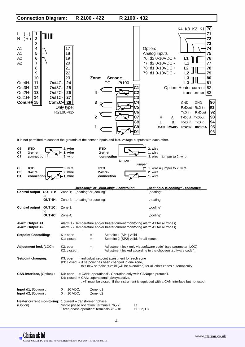
Connection Diagram: R 2100 - 422 R 2100 - 432
K4 K3 K2 K1 70L ( - ) 1 71N ( + ) 2 72
3 73A1 4 17 Option: 74A1 5 18 Analog inputs 75A2 6 19 76: d2 0-10VDC + L1 76A2 7 20 77: d2 0-10VDC - L1 77
8 21 78: d1 0-10VDC + L2 78 9 22 79: d1 0-10VDC - L2 79 10 23 Zone: Sensor: L3 80
Out4H- 11 Out4C- 24 TC Pt100 L3 81Out3H- 12 Out3C- 25 - C1 Option: Heater current 82Out2H- 13 Out2C- 26 4 C2 transformer 83Out1H- 14 Out1C- 27 C3Com.H+ 15 Com.C+ 28 3 - C4 GND GND 90 Only type: C5 RxDout RxD in 91
R2100-43x - C6 TxD in RxDout 92 2 C7 H A TxDout TxDout 93 C8 L B RxD in TxD in 94
1 - C9 CAN RS485 RS232 0/20mA 95D1 96
It is not permitted to connect the grounds of the sensor-inputs and bist. voltage-outputs with each other.
C6: RTD 2. wire RTD 2. wireC7: 3-wire 1. wire 2-wire 1. wireC8: connection 3. wire connection 3. wire = jumper to 2. wire
jumper jumper
C8: RTD 3. wire RTD 3. wire = jumper to 2. wireC9: 3-wire 2. wire 2-wire- 2. wireD1: connection 1. wire connection 1. wire
„heat-only“ or „cool-only“ - controller: „heating-o ff-cooling“ - controller: Control output OUT 1H: Zone 1; „heating“ or „cooling“ „heating“
toOUT 4H: Zone 4; „heating“ or „cooling“ „heating
Control output OUT 1C: Zone 1; „cooling“ toOUT 4C: Zone 4; „cooling“
Alarm Output A1: Alarm 1 ( Temperature and/or heater current monitoring alarm A1 for all zones)Alarm Output A2: Alarm 2 ( Temperature and/or heater current monitoring alarm A2 for all zones)
Setpoint Controlling: K1: open = Setpoint 1 (SP1) validK1: closed = Setpoint 2 (SP2) valid, for all zones
Adjustment lock (LOC): K2: open = Adjustment lock only via „software code“ (see parameter: LOC)K2: closed. = Adjustment locked according to the choosen „software code“.
Setpoint changing: K3: open = individual setpoint adjustment for each zoneK3: closed = if setpoint has been changed in one zone,
this new setpoint is valid (will be overtaken) for all other zones automatically.
CAN-Interface, (Option) : K4: open = CAN: „operational“. Operation only with CANopen protocoll.K4: closed = CAN: „operational“ always active.
„k4“ must be closed, if the instrument is equipped with a CAN-interface but not used.
Input d1, (Option) : 0 ... 10 VDC, Zone: d1Input d2, (Option) : 0 ... 10 VDC, Zone: d2
Heater current monitoring: 1 current – transformer / phase(Option) Single phase operation: terminals 76,77: L1
Three-phase operation: terminals 76 – 81: L1, L2, L3
Clarian uk ltd www.clarian.co.ukClarian UK Ltd. PO Box 185, Royston, Hertfordshire, SG8 5UY Tel. 01763 246319

5
Connection Diagram: R 2100 - 426 R 2100 - 436
K4 K3 K2 K1 70L ( - ) 1 71N ( + ) 2 72
3 73A1 4 17 Option: 74A1 5 18 Analog inputs 75A2 6 19 76: d2 0-10VDC + L1 76A2 7 20 77: d2 0-10VDC - L1 77
8 21 78: d1 0-10VDC + L2 78 9 22 79: d1 0-10VDC - L2 79 10 23 Zone: Sensor: L3 80
Out4H+ 11 Out4C+ 24 TC Pt100 L3 81Out3H+ 12 Out3C+ 25 - C1 Option: Heater current 82Out2H+ 13 Out2C+ 26 4 C2 transformer 83Out1H+ 14 Out1C+ 27 C3Com.H- 15 Com.C- 28 3 - C4 GND GND 90 Only type: C5 RxDout RxD in 91
R2100-43x - C6 TxD in RxDout 92 2 C7 H A TxDout TxDout 93 C8 L B RxD in TxD in 94
1 - C9 CAN RS485 RS232 0/20mA 95D1 96
It is not permitted to connect the grounds of the sensor-inputs and bist. voltage-outputs with each other.
C6: RTD 2. wire RTD 2. wireC7: 3-wire 1. wire 2-wire 1. wireC8: connection 3. wire connection 3. wire = jumper to 2. wire
jumper jumper
C8: RTD 3. wire RTD 3. wire = jumper to 2. wireC9: 3-wire 2. wire 2-wire- 2. wireD1: connection 1. wire connection 1. wire
„heat-only“ or „cool-only“ - controller: „heating-o ff-cooling“ - controller: Control output OUT 1H: Zone 1; „heating“ or „cooling“ „heating“
toOUT 4H: Zone 4; „heating“ or „cooling“ „heating
Control output OUT 1C: Zone 1; „cooling“ toOUT 4C: Zone 4; „cooling“
Alarm Output A1: Alarm 1 ( Temperature and/or heater current monitoring alarm A1 for all zones)Alarm Output A2: Alarm 2 ( Temperature and/or heater current monitoring alarm A2 for all zones)
Setpoint Controlling: K1: open = Setpoint 1 (SP1) validK1: closed = Setpoint 2 (SP2) valid, for all zones
Adjustment lock (LOC): K2: open = Adjustment lock only via „software code“ (see parameter: LOC)K2: closed. = Adjustment locked according to the choosen „software code“.
Setpoint changing: K3: open = individual setpoint adjustment for each zoneK3: closed = if setpoint has been changed in one zone,
this new setpoint is valid (will be overtaken) for all other zones automatically.
CAN-Interface, (Option) : K4: open = CAN: „operational“. Operation only with CANopen protocoll.K4: closed = CAN: „operational“ always active.
„k4“ must be closed, if the instrument is equipped with a CAN-interface but not used.
Input d1, (Option) : 0 ... 10 VDC, Zone: d1Input d2, (Option) : 0 ... 10 VDC, Zone: d2
Heater current monitoring: 1 current – transformer / phase(Option) Single phase operation: terminals 76,77: L1
Three-phase operation: terminals 76 – 81: L1, L2, L3
Clarian uk ltd www.clarian.co.ukClarian UK Ltd. PO Box 185, Royston, Hertfordshire, SG8 5UY Tel. 01763 246319
6
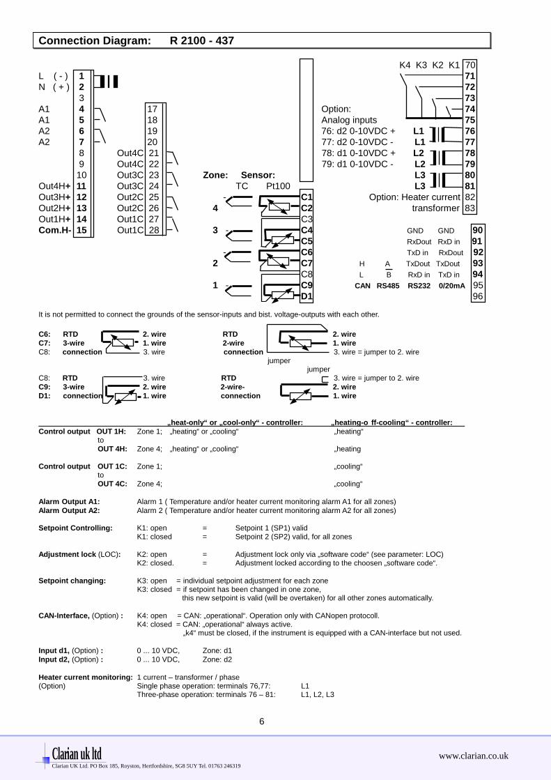
Connection Diagram: R 2100 - 437
K4 K3 K2 K1 70L ( - ) 1 71N ( + ) 2 72
3 73A1 4 17 Option: 74A1 5 18 Analog inputs 75A2 6 19 76: d2 0-10VDC + L1 76A2 7 20 77: d2 0-10VDC - L1 77
8 Out4C 21 78: d1 0-10VDC + L2 78 9 Out4C 22 79: d1 0-10VDC - L2 79 10 Out3C 23 Zone: Sensor: L3 80
Out4H+ 11 Out3C 24 TC Pt100 L3 81Out3H+ 12 Out2C 25 - C1 Option: Heater current 82Out2H+ 13 Out2C 26 4 C2 transformer 83Out1H+ 14 Out1C 27 C3Com.H- 15 Out1C 28 3 - C4 GND GND 90 C5 RxDout RxD in 91
- C6 TxD in RxDout 92 2 C7 H A TxDout TxDout 93 C8 L B RxD in TxD in 94
1 - C9 CAN RS485 RS232 0/20mA 95D1 96
It is not permitted to connect the grounds of the sensor-inputs and bist. voltage-outputs with each other.
C6: RTD 2. wire RTD 2. wireC7: 3-wire 1. wire 2-wire 1. wireC8: connection 3. wire connection 3. wire = jumper to 2. wire
jumper jumper
C8: RTD 3. wire RTD 3. wire = jumper to 2. wireC9: 3-wire 2. wire 2-wire- 2. wireD1: connection 1. wire connection 1. wire
„heat-only“ or „cool-only“ - controller: „heating-o ff-cooling“ - controller: Control output OUT 1H: Zone 1; „heating“ or „cooling“ „heating“
toOUT 4H: Zone 4; „heating“ or „cooling“ „heating
Control output OUT 1C: Zone 1; „cooling“ toOUT 4C: Zone 4; „cooling“
Alarm Output A1: Alarm 1 ( Temperature and/or heater current monitoring alarm A1 for all zones)Alarm Output A2: Alarm 2 ( Temperature and/or heater current monitoring alarm A2 for all zones)
Setpoint Controlling: K1: open = Setpoint 1 (SP1) validK1: closed = Setpoint 2 (SP2) valid, for all zones
Adjustment lock (LOC): K2: open = Adjustment lock only via „software code“ (see parameter: LOC)K2: closed. = Adjustment locked according to the choosen „software code“.
Setpoint changing: K3: open = individual setpoint adjustment for each zoneK3: closed = if setpoint has been changed in one zone,
this new setpoint is valid (will be overtaken) for all other zones automatically.
CAN-Interface, (Option) : K4: open = CAN: „operational“. Operation only with CANopen protocoll.K4: closed = CAN: „operational“ always active.
„k4“ must be closed, if the instrument is equipped with a CAN-interface but not used.
Input d1, (Option) : 0 ... 10 VDC, Zone: d1Input d2, (Option) : 0 ... 10 VDC, Zone: d2
Heater current monitoring: 1 current – transformer / phase(Option) Single phase operation: terminals 76,77: L1
Three-phase operation: terminals 76 – 81: L1, L2, L3
Clarian uk ltd www.clarian.co.ukClarian UK Ltd. PO Box 185, Royston, Hertfordshire, SG8 5UY Tel. 01763 246319
7
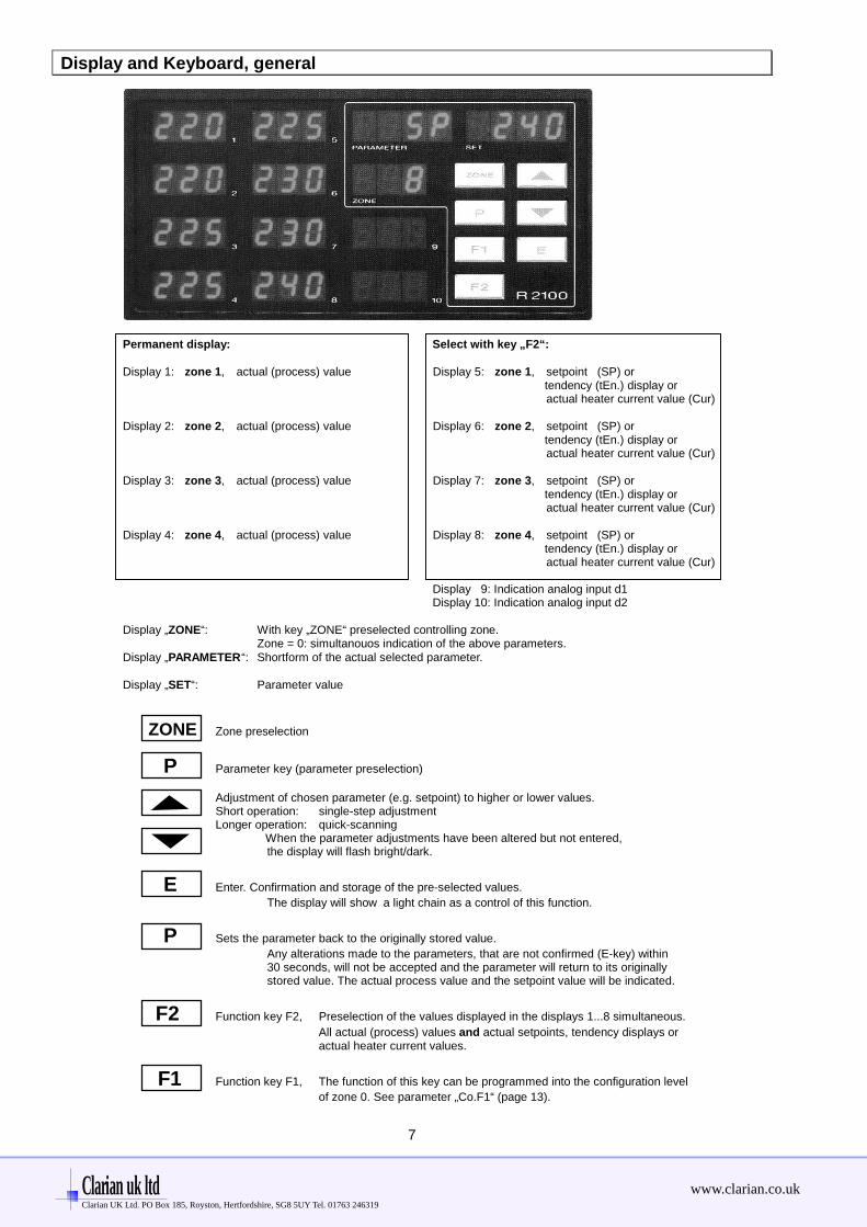
Display and Keyboard, general
Permanent display: Select with key „F2“:
Display 1: zone 1, actual (process) value Display 5: zone 1, setpoint (SP) or tendency (tEn.) display or
actual heater current value (Cur)
Display 2: zone 2, actual (process) value Display 6: zone 2, setpoint (SP) or tendency (tEn.) display or
actual heater current value (Cur)
Display 3: zone 3, actual (process) value Display 7: zone 3, setpoint (SP) or tendency (tEn.) display or
actual heater current value (Cur)
Display 4: zone 4, actual (process) value Display 8: zone 4, setpoint (SP) or tendency (tEn.) display or
actual heater current value (Cur)
Display 9: Indication analog input d1 Display 10: Indication analog input d2
Display „ZONE“: With key „ZONE“ preselected controlling zone.Zone = 0: simultanouos indication of the above parameters.
Display „PARAMETER“: Shortform of the actual selected parameter.
Display „SET“: Parameter value
ZONE Zone preselection
P Parameter key (parameter preselection)
Adjustment of chosen parameter (e.g. setpoint) to higher or lower values.Short operation: single-step adjustmentLonger operation: quick-scanning
When the parameter adjustments have been altered but not entered,the display will flash bright/dark.
E Enter. Confirmation and storage of the pre-selected values.
The display will show a light chain as a control of this function.
P Sets the parameter back to the originally stored value.
Any alterations made to the parameters, that are not confirmed (E-key) within30 seconds, will not be accepted and the parameter will return to its originallystored value. The actual process value and the setpoint value will be indicated.
F2 Function key F2, Preselection of the values displayed in the displays 1...8 simultaneous.
All actual (process) values and actual setpoints, tendency displays oractual heater current values.
F1 Function key F1, The function of this key can be programmed into the configuration level
of zone 0. See parameter „Co.F1“ (page 13).
Clarian uk ltd www.clarian.co.ukClarian UK Ltd. PO Box 185, Royston, Hertfordshire, SG8 5UY Tel. 01763 246319

8
Display: - Process values and setpoints - Process values and tendency, control output and alarm indication
- Process values and actual heater current values
After switching on the unit,the process values (actual values) and the setpoints of zones 1...4 will be displayed simultaneously::
Zone 1: Zone 1: P.SPx P.SPx:process 1 setpoint 5 P: Process value
PARAMETER SET andZone 2: Zone 2: SP1: Setpoint 1process 2 setpoint 6 0 SP2: Setpoint2
Zone 3: Zone 3: ZONEprocess 3 setpoint 7
Zone 4: Zone 4:process 4 setpoint 8
Press key F2: Display switches from setpoint indication over to tendency and alarm indication of zones 1...4:
Zone 1: Zone 1: tEn. tEN:process 1 a1-te-a2 5 a1: alarm A1 indication
PARAMETER SET te.: tendency andZone 2: Zone 2: output indicationprocess 2 a1-te-a2 6 0 a2: alarm A2 indication
Zone 3: Zone 3: ZONEprocess 3 a1-te-a2 7
Zone 4: Zone 4:process 4 a1-te-a2 8
Interpretation of the symbols: see next page
Only OPTION: Heater current monitoring
Press key F2: Display switches from tendency and alarm indication over to actual heater current value indication of zones 1...4:
Zone 1: Zone 1: Cur. Cur:process 1 current 5 Cur: Actual Heater current
PARAMETER SET value indication Zone 2: Zone 2: of zones 1 - 4
process 2 current 6 0 in displays 5 - 8
Zone 3: Zone 3: ZONEprocess 3 current 7
Zone 4: Zone 4:process 4 current 8
Press key F2: Display switches back to process value and setpoint indication. Zones: 1...4.
Clarian uk ltd www.clarian.co.ukClarian UK Ltd. PO Box 185, Royston, Hertfordshire, SG8 5UY Tel. 01763 246319

9
Tendency, control output and alarm indication
With the help of key „F2“ a temperature tendency display will be shown, to give an overview about the temperaturesdeviations relating to the setpoints, the activity of the control outputs and an alarm indication in the individual controllerzones.
For each zone are 3 digits available (displays 1...8) :
Digit a1: Indication = 1, if alarm message A1 is active in this zone.
Digit te: Temperature tendency digit.
Digit a2: Indication = 2, if alarm message A2 is active in this zone.
a1 te a2
a1 te a2
O =Self tuning algorithm (Opt.) : active
a1 te a2
H = Manual mode (Hand) Dec.-point flashed acc. to the actual output ratio
The symbols in digit „te“ (Temperatur tendency ) have to be interpreted as follows:
actual value > SP + 0,5 %
temperature o.k.
actual value < SP - 0,5 %
heating: heating: heating: heating: zone: Sensor erroron off off on off short circuit
(bottom range end)or and sensor breakage
(top range end)cooling cooling or wrong connection.on off
The flashing dec.-point shows, that either „heating“- or „cooling“-output is active.
Clarian uk ltd www.clarian.co.ukClarian UK Ltd. PO Box 185, Royston, Hertfordshire, SG8 5UY Tel. 01763 246319

10
Operating Levels
The operation of the controller is divided into 3 levels.In zone 0 general settings have to be made.
and and
press press appr. 5 sec.
Parameter- Configuration-Controller: Operating level level level“on“
process value Y ( output ratio ) Zone : on / OFF (process)
setpoint value (set)
Y ConF
1Y.Hi SEn
Alarm A1Alarm A2 OFSt COPY
Back into the operation level:
- Press 1 sec. or automatically after appr. 30 sec.
Operating level (for each zone separatly):Process- and Setpoint value will be displayed simultaneously. Within the operating level the setpoint can be adjustedby pressing the " " / " " - keys.Every adjustment has to be quit by pressing the „ E “ - key.All parameters within the operating level ( including the alarm values ) can , in succession, be displayed by pressing the „ P “ - key andadjusted by pressing the " " / " " - keys. Quit by pressing the „ E “ - key.
Parameter level (for each zone separatly):Within the parameter level the values are adjusted to suit each individual process.This level is reached by simultaneously pressing the "P" - and " E " -keys.The display of each single parameter within the parameter level and their adjustment,are made in the same fashion as within the operating level.After either pressing the „E“ - key for approx. 1 second, or waiting for a period of approx. 30 seconds,the unit will automatically return to the operating level (display of process value and setpoint).
Configuration level: This primary informations have to be entered before taking the instrument into operation.The configuration level is reached by simultaneously pressing the "P" - and " E " - keys for a period of approx. 5 seconds.First choose the configuration level in zone 0. Here general settings have to be made.This has to be programmed at first:- Only TC- or RTD-connection for all zones? Or: Mixed connection ?- Alarm configuration (valid for all zones) - Function of key „F1“- Software key - Serial interface informations- Heater current monitoring system
Than choose the configuration level of each individual controller zone.This has to be programmed at second:- Controller type (for each zone)- Input type (sensor type), sensor range(for each zone)- Min. and max. setpoint range (for each zone)The display of each single parameter within the configuration level and their adjustment, made in the same fashion as within theoperating level.There is also a copy function available. So it is possible, to copy the programmed parameters of one zone to other zones.After either pressing the „E“ - key for approx. 1 second, or waiting for a period of approx. 30 seconds,the unit will automatically return to the operating level (display of process value and setpoint).
P
E
E
P P
P
P
P
E
P
P
Clarian uk ltd www.clarian.co.ukClarian UK Ltd. PO Box 185, Royston, Hertfordshire, SG8 5UY Tel. 01763 246319

11
Configuration Level, general ( select zone 0 and press „P“ - and „E“ - key appr. 5sec.,
general settings )
Display Parameter Display"PROCESS" „SET“
P - tc Sensor mix - 4 all 4 zones: prepared for thermocouple - connection2 2 zones 1 - 2 : RTD - connection; zones 3 - 4 : Thermocouple connection4 - all 4 zones: prepared for RTD - connection
Co.A1 Alarm 1-Configuration The selected configuration is effective for all control zones.(switches relay A1) The individual temperature alarms A1 of all zones are connected
to the main, common contact A1.If a control zone indicates a fault (sensor short circuit / break ),the alarm output A1 is generally switched.
OFF alarm OFF, no alarm signalisation (ex works)1 signal contact, setpoint depentend: off-on2 limit contact, process value depentend: off-on3 limit comparator: off-on-off4 signal contact: on-off5 limit contact: on-off6 limit comparator: on-off-on7 limit comp. with start-up suppression: off-on-off8 heater current monitoring; limit contact: off-on; see page 129 heater current monitoring; limit contact: on-off; see page 12
The signal contact is adjusted and displayed The limit contact is adjusted and displayed relative to the setpoint (deviation alarm). as an absolute value. Switching behaviour: Configuration: Switching behaviour: Configuration:
off on 1 off on 2, 8
on off 4 on off 5, 9
setpoint process process
The limit comparator is adjusted and displayed The alarm relay of the limit comparator with relative to the setpoint. The selected start-up suppression is activated when the controller value is effective below and above the setpoint. is first switched on. It is only then deactivated, when the
process value has been within, and left, the o.k. -zone. Switching behaviour: Configuration: Switching behaviour: Configuration:
on off on off 3 off on off 7
on off on 6
setpoint process setpoint process
Please note:In case of sensor error the alarms will react in the same way as range override. The alarm contacts therefore do not offer protectionagainst all types of plant breakdown. With this in mind, we recommend the use of a second, independent monitor unit.Care should be used to ensure, that the setpoints of the alarm contacts are programmed within the selected measuring range.If a setpoint ramp has been programmed, the alarms that are relative to the setpoint (signal contact, limit comparator) follow thesetpoint up the ramp.
signal value
limit range
limit value
limit range
Clarian uk ltd www.clarian.co.ukClarian UK Ltd. PO Box 185, Royston, Hertfordshire, SG8 5UY Tel. 01763 246319

12
Display Parameter Display"PARAMETER" „SET“
rE.A1 Relay A1switching behaviour dir on: LED = „1“ Relay A1 "activated"
off: LED = „1“ Relay A1 "not active"
inv on: LED = „1“ Relay A1 "not active" off: LED = „1“ Relay A1 "activated"
Co.A2 Alarm 2-Configuration see Co.A1 (alarm 1 - configuration)(switches relay A2)
rE.A2 Relay A2switching behaviour dir on: LED = „2“ Relay A2 "activated",
off: LED = „2“ Relay A2 "not active",
inv on: LED = „2“ Relay A2 "not active", off: LED = „2“ Relay A2 "activated",
Heater current monitoring
The following parameters will only be displayed if the heater current monitoring system is activated as descriped below:
Heater current monitoring via relay A1: Program parameter Co.A1 to number 8 or 9Heater current monitoring via relay A2: Program parameter Co.A2 to number 8 or 9
The heater current to be monitored, has to be programed as an absolute value into the operatinglevel for both relays A1 and A2.See: Operating level, Parameter „A1“ or „A2“.
Please note if the supply voltage is low the heater current is higher than the monitoring value otherwise the alarm signal will beactivated.If the heater current value falls below the monitoring value, an alarm signal (the relay switches) willbe activated.With the help of the parameter „dL.Ax“ it is possible to program a delay time.If you do so, it is virtually impossible to get an unauthorized alarm signal.When switching the power-on, the alarm signalisation will be suppressed until the heating current values for all zones has beenscanned and verified.The monitoring function and all possible adjustments are valid for all connected heating zones.
Display Parameter- Parameter valuePROCESS" description Display „SET“
dL.A1 delay time, relay A1 5 steps adjustable (in sec.) Adjustment and display in seconds.If alarm relay A1 is selected OFF= no delay time The values are dependent on thefor the heater current current detection interval time and themonitoring. number of active controller zones.
dL.A2 delay time, relay A2 5 steps adjustable (in sec.) Adjustment and display in seconds.If alarm relay A2 is selected OFF= no delay time The values are dependent on thefor the heater current current detection interval time and themonitoring. number of active controller zones.
Clarian uk ltd www.clarian.co.ukClarian UK Ltd. PO Box 185, Royston, Hertfordshire, SG8 5UY Tel. 01763 246319

13
Display Parameter- Parameter value„PARAMETER" description Display „SET“
Cu.CY Current detection intervall 1 ... 60 sec. Time between the current measuringof two zones following each other.
C x.x Min. leakage current value OFF; Adjustment of the allowed min.and leakage current display 0,0...99,9 A leakage current value.with continous current display. The heater current will be monitored
to detect circuits with an eventualleakage current (e.g. SSR damage).
SSR`s (especially if they are combined with RC-combinations) normally have small leakage currents.Heaters also have small leakage currents.
The actual leakage current will be displayed in display „PROCESS“.Via display „SET“ the min. allowed leakage current value can be adjusted.Currents below this value will be ignored.
If a permanent current is detected in one zone the alarm relay will be activated andthe display „PROCESS“ will show the error signalisation „Er.Cu“.The zone with a measured permanent current can be located by pressing the zonekey and watching all temperature indications.Display indication in this case: „Comparable with„temperature too high.“But there is no special indication via tendency- or alarm status display.
Display: C 0.2 1.0
PARAMETER SET
Leakage current: 0,2A Min. leakage current value: 1,0A
Er. Cu
PARAMETER SET
Permanent current detected in one zone.Error signalisation: flashing
Display Parameter- Parameter value„PARAMETER" description Display „SET“
Co.F1 Select funktion OFF No functionof key „F1“ OPt Selftuning algorithm can be activated by pressing key „F1“
in the matching zone. „F1“ and „E“: stop selftuning. Y Shows the actual percentage output ratio, while pressing „F1“.
Display „PARAMETER“: YLEd.t Lamp (LED) test, while pressing „F1“.
LOC Adjustment lock OFF No adjustment lock (ex works)P C Parameter and configuration levels lockedn.SP1 All parameters apart from SP1 locked (not SP1)ALL All parameters locked
All parameters that have been locked with „LOC“ can be selected and read, but not altered.This adjustment cannot be changed if the external contact K2 is closed.
Zo.OF Zones offset preselection OFF No offset preselection. Zones indication: 1 - 4(Continuous numbering of 1 - 95 Zones will be numbered with preselected offset value.the controller zones) Beisp.: Zo.OF = 1 -> Zone indication: 2 - 5
Zo.OF = 8 -> Zone indication: 9 - 12
Clarian uk ltd www.clarian.co.ukClarian UK Ltd. PO Box 185, Royston, Hertfordshire, SG8 5UY Tel. 01763 246319

14
Display Parameter- Parameter value„PARAMETER" description Display „SET“
The following parameters are only valid, if the unit is equipped with a serial interface.RS232, RS485, 0/20mA.
Prot Protocol preselection ELO ELOTECH- standard protocolIbS Gateway-protocol valid for Profibus-DP, InterBus-S, DeviceNet
Only with RS 485-interface (Code-No.: 4).
Adr Unit adress 1 .... 255 (ex works: 1)The computer adresses the unit/controller at this adress.Each unit has ist own adress. With RS-485 it is possible to adress 32 units.
For Data format 7E1 7 data, even, 1 stopbit7o1 7 data, odd, 1 stopbit7E2 7 data, even, 2 stopbit7o2 7 data, odd, 2 stopbit7n2 7 data, none, 2 stopbit8E1 8 data, even, 1 stopbit8o1 8 data, odd, 1 stopbit8n1 8 data, none, 1 stopbit Profibus-DP, InterBus-S, DeviceNet8n2 8 data, none, 2 stopbit
bAud Baud rate OFF; 0,3 ... 9,6 kBaudThe baud rate denotes the transmission rate at which one bit is transmitted.Profibus-DP, InterBus-S, DeviceNet = 9,6 kBaud
Details: See: - sep. interface description: ELOTECH – standard-protocol- sep. interface description: Gateway: M-PBS-5, M-IBS-5, M-DN-5
The following parameters are only valid, if the unit is equipped with a CAN interface.
Adr Unit adress 1 .... 127 (ex works: 1)
tiM CAN - timing CIA acc. to CiA - recommendation (ex works: CIA)StZP acc. to StZP - recommendation
bAud Baud rate 10, 20, 50, 100, 125, 250, 500 kBaud (ex works: 20)
CANopen-specfication: CANopen Master: noCANopen Slave: yesExtended Boot-up: noMinimum Boot-up: yesCOB ID Distribution: yes; default via SDONode ID Distribution: no; via device keyboardNo. of POD´s: 0RX, 1TXPDO Modes: async.Variable PDO mapping: noEmergency message: yesLife guarding: yesNo. of SDO`s: 1RX, 1TXDevice Profile: CiA DS-404
Details: See: CANopen Device Profile CiA DS-404; ELOTECH Object Dictionary
21xxEL.xx Control number No function. End of configuration level
Clarian uk ltd www.clarian.co.ukClarian UK Ltd. PO Box 185, Royston, Hertfordshire, SG8 5UY Tel. 01763 246319

15
Configuration Level Individual selectable for zones 1 ... 4
(select zone and press „P“ - and „E“ - key appr. 5sec. )
Display Parameter Display"PARAMETER" „SET“
Zone Zone on / off OFF measuring- or controller zone „off“on measuring- or controller zone „on“
ConF Controller configuration 2P h 2-point-controller „heating-off“ (ex works)2P c 2point-controller „cooling-off“2Pnc 2point-controller „cooling-off“ with non-linear cooling *).3P 3point-controller „heating-off-cooling“ ( Only type: R2100-43x )3Pn c 3point-controller „heating-off-cooling“ with non-linear cooling *)
( Only type: R2100-43x )*) non-linear cooling:Cooling action can be pre-selected with either linear ornon-linear cooling response curve ( e.g. for vapour cooling).
diSP Zone works as an indicator, no controller action
SEn Sensor selection P1 °C Pt 100, 0,0 ...99,9 °CP1 °F Pt 100, 32 ...212 °FP2 °C Pt 100, -100 ...+100 °CP2 °F Pt 100, -148 ... +392 °FP4 °C Pt 100, 0 ... 400 °C (ex works)P4 °F Pt 100, 32 ... 752 °FP8° C Pt 100, 0 ... 800 °C
or, if selected as a thermocouple-input zone (depending on parameter „P - tc“ in Zone 0):
L4 °C T/C Fe-CuNi (L), 0 ... 400 °CL4 °F T/C Fe-CuNi (L), 32 ... 752 °FL8 °C T/C Fe-CuNi (L), 0 ... 800 °CJ8 °C T/C Fe-CuNi (J), 0 ... 800 °Cn1 °C T/C NiCr-Ni (K), 0 ... 999 °C
If the Sensor selection is changed, the following parameters will be set as follows and need to be re-adjusted:Setpoint 1, setpoint 2: SP.Lo Process value offset: OFFLower setpoint limitation: Bottom range end; Higher setpoint limitation: Top range end;Setpoint-ramp values: OFF; Alarm values: OFF;
OPTION: The following parameters are only valid for zones d1 and d2 (Input: 0...10 Vdc).It is to configurate the display range of the 0...10 Vdc inputs.The difference between the bottom end of the display range and the top end must amount to a minimum of100 units and a maximum of 2000 units. By adjustment of one of the above parameters, the otherin this case will automatically follow.
unit selectable physical. unit Shown in the display „parameter“, when zone d1 or d2 selected( e.g. : °C, °F, bar, volt ... ). Display „set“ shows additional the actual value.
rA.dP decimal points 0; 1; 2 (ex works: 1)rA.Hi display range top end rA.Lo ... 9999 (ex works: 100,0)rA.Lo display range bottom end -1999 ... rA.Hi (ex works: 0,0)
SP.Hi higher setpoint limitation programming range: SP.Lo ... top range (ex works: 400)
SP.Lo lower setpoint limitation programming range: bottom range ... SP.Hi (ex works: 0)
COPY Copy function to 1 ... to x Copy all configuration datas of the actual zone 1 to zone x.Select the target zone 1, 2 .... or „to A“ (all) with the „up/down“ - keysand press „E“ (enter). After this, the datas would be copied.Note: It is only possible to copy the configuration, if the sensorconfiguration ( Parameter: P - tc ) in the target-zone is the same as in theactual zone. This means, that it is not possible, to copy configurations ofe.g. RTD-input zones to thermocouple-input zones.
Clarian uk ltd www.clarian.co.ukClarian UK Ltd. PO Box 185, Royston, Hertfordshire, SG8 5UY Tel. 01763 246319

16
Display Parameter Display"PARAMETER" „SET“
Softstart-function
TAKE CARE: If you take the softstart-function, make sure that the heating control outputs areequipped with bistable voltage (logic) outputs.This function is not allowed for instruments with relay-outputs(in this case set So.St = OFF).Otherwise the relais will be destroid becuse they switch too fast.
Softstart (general function):During the softstart the controllers’ heating output response is limited to a pre-selected ratio, in orderto achieve a slow baking out of high performance heat cartridges.Simultaneously the output clock frequency is quadrupled. Once the process value reachesthe softstart setpoint, it remains stable at this value for a pre-selcted hold-duration time.At the end of this period the process value rises to the valid setpoint.This results in a slower, more regular heating period.For this purpose the bistable voltage output must be taken, that actuates SSR relays.If the softstart is active, the controllers’ autotune function can’t operated (Er.OP).If a setpoint-ramp has been programmed, the softstart has priority, and the ramp will onlybecome active after the softstart has been completed.
The softstart only works,- if the parameter „1 P“ (prop. band, xp) is programmed > 0,1%.- if the actual process value is lower than So.SP – 5% of the selected measuring range.
It is possible, to select this function for each zone individally.
Setpoint SP
So.SP Softstart setpoint
So. Y So.ti
t
So.St Softstart-function OFF: Softstart not active (ex works)Next parameter So.Y, So.SP, So.ti are not shown.
On: Softstart in action.The softstart function always runs, if the controller is switched on and / orif the actual temperature is below the softstart setpoint So.SP minus 5%of the range (e.g. range: 400^C -> 5%= 20°C).
So. Y Softstart output ratio 10 ... 100%
So.SP Softstart setpoint range: SP.Lo .... SP.Hi
So.ti Softstart duration time OFF; 0,1 ... 10,0 min.
Clarian uk ltd www.clarian.co.ukClarian UK Ltd. PO Box 185, Royston, Hertfordshire, SG8 5UY Tel. 01763 246319
17
Display Parameter Display"PARAMETER" „SET“
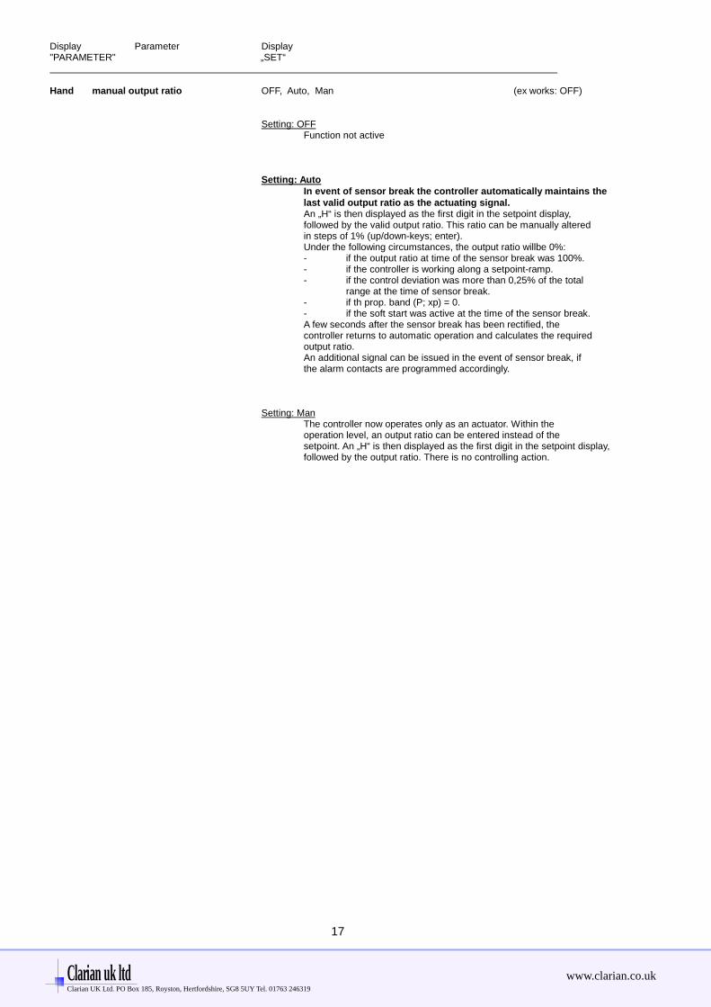
Hand manual output ratio OFF, Auto, Man (ex works: OFF)
Setting: OFFFunction not active
Setting: AutoIn event of sensor break the controller automatically maintains thelast valid output ratio as the actuating signal.An „H“ is then displayed as the first digit in the setpoint display,followed by the valid output ratio. This ratio can be manually alteredin steps of 1% (up/down-keys; enter).Under the following circumstances, the output ratio willbe 0%:- if the output ratio at time of the sensor break was 100%.- if the controller is working along a setpoint-ramp.- if the control deviation was more than 0,25% of the total
range at the time of sensor break.- if th prop. band (P; xp) = 0.- if the soft start was active at the time of the sensor break.A few seconds after the sensor break has been rectified, thecontroller returns to automatic operation and calculates the requiredoutput ratio.An additional signal can be issued in the event of sensor break, ifthe alarm contacts are programmed accordingly.
Setting: ManThe controller now operates only as an actuator. Within theoperation level, an output ratio can be entered instead of thesetpoint. An „H“ is then displayed as the first digit in the setpoint display,followed by the output ratio. There is no controlling action.
Clarian uk ltd www.clarian.co.ukClarian UK Ltd. PO Box 185, Royston, Hertfordshire, SG8 5UY Tel. 01763 246319

18
Parameter Level Individual selectable for zones 1 ... 4
(select zone and press „P“ - and „E“ - key appr. 1sec. )
Display Parameter Display"PARAMETER" „SET“
Y valid output ratio -100...100 % The output ratio shows the momentary calculated ratio.It cannot be altered. The display is in percent of the installedperformance capability for heating or cooling.Output ratio for cooling is shown as a negative value.
1Y.Hi output ratio limit 0...100 % (ex works: 100)„heating“ Limitation of the output ratio is only necessary when:
the heating or cooling energy supply is grossly over-dimensioned compared to the power required, orto turn off a control output (setting = 0%). Undernormal circumstances no limitation is needed (setting = 0%).The limitation becomes effective, when the controllers’ calculatedoutput ratio is greater than the maximum permissible (limited) ratio.Warning!The output ratio limitation does not work during autotune.
2Y.Hi output ratio limit 0...100 % (ex works: 100)„cooling“ Only types: R2100-63x and R2100-83x and
Configuration: heating-off-cooling controller
1 P Xp, prop.-band (P) OFF; 0,1...100,0 % (ex works: 3,0)„heating“ If „ 1 P “ = OFF (control action: on-off, without feedback)
next parameter: „ 1 sd “.
1 d Tv, rate (D) OFF; 1...200 secs (ex works: 30)„heating“
1 J Tn, reset (I) OFF; 1...1000 secs (ex works: 150)„heating“ Normally the controller works using PD/I control action.
This means, controlling without deviation and with practicallyno overshoot during start-up.The control action can be altered in its structure by making thefollowing adjustments to the parameters:a. no control action, on-off (setting P = OFF)b. P-action (setting D and I = 0)c. PD-action (setting I = 0)d. PI-action (setting D = 0)e. PD/I modified PID-action
1 C cycle time 0,5...240,0 secs (ex works: 10,0)„heating“ The switching frequency of the actuator can be determined
by adjusting the cycle time. This is the total time needed for thecontroller to switch on and off once.
a) Relay outputs: cycle time > 10 secsb) Bistable voltage outputs: cycle time 0,5...10 secs
1 Sd Control sensivity Only if: 1 P = Xp = OFF (On-off action, without feedback)output „heating“ OFF; 0,1...80,0 °C (ex works: 0,1)
Sd = 10,0
on
-5,0 +5,0 off
SETPOINT PROCESS VALUE
Clarian uk ltd www.clarian.co.ukClarian UK Ltd. PO Box 185, Royston, Hertfordshire, SG8 5UY Tel. 01763 246319

19
Display Parameter Display"PARAMETER" „SET“
The following parameters apply only to types R 2100 - 43x andif configurated as heat-off-cool controllers ( configuration: „3 P“ or „3Pnc“ ):
Sh switch-point difference OFF; 0,1...80,0 °C/°F (ex works: OFF)OFF; 0,01...8,00 °C/°F
This parameter raises the setpoint (switch-point) for cooling outputby the displayed value. It can be help to reduce the switchingfrequency between the heating and cooling outputs, if this is to high.Simultaneously activation of heat and cool outputs is not possible.
2 P Xp, prop. band (P) OFF; 0,1...100,0 % (ex works: 3,0)„cooling“ If „ 2 P “ = OFF (control action: on-off, without feedback)
next parameter: „ 2 sd “.
2 d Tv, rate (D) OFF; 1...200 secs (ex works: 30)„cooling“
2 J Tn, reset (I) OFF; 1...1000 secs (ex works: 150)„cooling“
Normally the controller works using PD/I control action.This means, controlling without deviation and with practicallyno overshoot during start-up.The control action can be altered in its structure by making thefollowing adjustments to the parameters:a. no control action, on-off (setting P = OFF)b. P-action (setting D and I = 0)c. PD-action (setting I = 0)d. PI-action (setting D = 0)e. PD/I modified PID-action
2 C cycle time 0,5...240,0 secs (ex works: 10,0)„cooling“ The switching frequency of the actuator can be determined
by adjusting the cycle time. This is the total time needed for thecontroller to switch on and off once.a) Relay outputs: cycle time > 10 secsb) Bistable voltage outputs: cycle time 0,5...10 secs
2 Sd Control sensivity„cooling“ Only if: 2 P = Xp = OFF (On-off action, without feedback)
OFF; 0,1...80,0 °C (ex works: 0,1)
Clarian uk ltd www.clarian.co.ukClarian UK Ltd. PO Box 185, Royston, Hertfordshire, SG8 5UY Tel. 01763 246319

20
Display Parameter Display"PARAMETER" „SET“
OPt self tuning OFF self tuning out of action(autotune) on self tuning on request ( one time)
The tuning algorithm determines the characteristic values within the controlled process, and calculatesthe valid feedback parameters ( P,D,I ) and the cycle time ( C = 0.3 x D ) of a PD/I-controller for a wide section of the range.
The self tuning activates during start-up shortly before the setpoint is reached. The setpoint mustamount to the least 5% of the total range.If activated after the setpoint has already been reached, the temperature will first drop by approx. 5%of the total range, in order to detect the exact amplification of the process.
The tuning algorithm can be activated at any time by selecting the OPT=on and pressing the „E“-key.During self tuning „Opt“ is shown in the display, alternating with the setpoint value.
Self tuning activ: „SPx“ flashes with „OPt“ - indication in display „PARAMETER“.
After having calculated the correct feedback parameters, the controller will lead the process value to the setpoint.
X X
Set Set
OPT on t OPT on tSelf tune Self tune, after the setpointduring start-up has already been reached
Self-tuning can be stopped by selecting the option OPT = OFF and pressing the „E“ - key.
OFSt process value offset -99 ... OFF ...100 Units (ex works: OFF)-9,9 ... OFF ... 10,0
This parameter serves to correct the input signal, e.g. for:- the correction of a gradient between the measuring point and the sensor tip,- the line resistance balancing of 2-line RTD (Pt100) sensors and- correction of the control devition when using P- or PD-action.
If for example the offset value is set to +5°C, then the real temperature measuredby the sensor (when process is balanced) is 5°C less than the setpoint and thedisplayed process value.
Clarian uk ltd www.clarian.co.ukClarian UK Ltd. PO Box 185, Royston, Hertfordshire, SG8 5UY Tel. 01763 246319
21
Operating Level ( individual selectable for zones 1 ... 4 )
Display Parameter Display"PARAMETER" „SET“
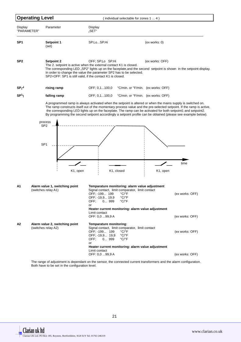
SP1 Setpoint 1 SP.Lo...SP.Hi (ex works: 0)(set)
SP2 Setpoint 2 OFF; SP.Lo SP.Hi (ex works: OFF)The 2. setpoint is active when the external contact K1 is closed.
The corresponding LED „SP2“ lights up on the faceplate,and the second setpoint is shown in the setpoint-display.In order to change the value the parameter SP2 has to be selected.SP2=OFF: SP1 is still valid, if the contact K1 is closed.
SP rising ramp OFF; 0,1...100,0 °C/min. or °F/min. (ex works: OFF)
SP falling ramp OFF; 0,1...100,0 °C/min. or °F/min. (ex works: OFF)
A programmed ramp is always activated when the setpoint is altered or when the mains supply is switched on.The ramp constructs itself out of the momentary process value and the pre-selected setpoint. If the ramp is active, the corresponding LED lights up on the faceplate. The ramp can be activated for both setpoint1 and setpoint2.By programming the second setpoint accordingly a setpoint profile can be oblained (please see example below).
process SP2
SP1
time
K1, open K1, closed K1, open
A1 Alarm value 1, switching point Temparature monitoring: alarm value adjustment(switches relay A1) Signal contact, limit comparator, limit contact
OFF; -199... 199 °C/°F (ex works: OFF)OFF; -19,9... 19,9 °C/°FOFF; 0... 999 °C/°ForHeater current monitoring: alarm value adjustmentLimit contactOFF: 0,0 ...99,9 A (ex works: OFF)
A2 Alarm value 2, switching point Temparature monitoring:(switches relay A2) Signal contact, limit comparator, limit contact
OFF; -199... 199 °C/°F (ex works: OFF)OFF; -19,9... 19,9 °C/°FOFF; 0... 999 °C/°ForHeater current monitoring: alarm value adjustmentLimit contactOFF: 0,0 ...99,9 A (ex works: OFF)
The range of adjustment is dependant on the sensor, the connected current transformers and the alarm configuration.Both have to be set in the configuration level.
Clarian uk ltd www.clarian.co.ukClarian UK Ltd. PO Box 185, Royston, Hertfordshire, SG8 5UY Tel. 01763 246319

22
D I S P L A Y ( OPTION: only inputs zone d1 and d2 , individual display )
Analogue Display Indicationvalue „Zone“
input d1 d1 Display 9: 0...10 Vdc, corresp. the progr. range (ex works: 0...100)
input d2 d2 Display 10: 0...10 Vdc, corresp. the progr. range (ex works: 0...100)
Clarian uk ltd www.clarian.co.ukClarian UK Ltd. PO Box 185, Royston, Hertfordshire, SG8 5UY Tel. 01763 246319

23
Technical Data
Input RTD, Pt 100 (DIN): 2 - or 3 - wire connection possible.Built-in protection against sensor breakage and short circuit.Max. permissible line resistance by 3-wire connection: 80 OhmsSensor current: < 1 mACalibration accuracy: < 0,2 %Linear error: < 0,2 %Influence of the ambient temperature: < 0,01 % / K
Input Thermocouple: Built-in internal compensation point and protection against sensor breakageand incorrect polarity.Re-calibration not required for a line resistance of up to 50 Ohms.Calibration accuracy: < 0,25%
Analog inputs (Option): 0 ... 10 V DC (Display range programmable)
Setpoint selection: Ext. potential-free contact, switching voltage appr. 24 V DC, max. 1 mA.Selection between SP1 and SP2 valid for all zones.
Control outputs OUT 1 ... OUT 4 : Bist. voltage signal, 0/18 V DC, max. 10 mA, short-circuit prooforRelay, max. 250 VAC, max. 3 A (cos-phi = 1)
Alarm outputs A1 and A2: Relay, max. 250 VAC, max. 3 A (cos-phi = 1)
7-Segment-Display: Process: 10 mm red, Set: 10 mm red
Data protection: EAROM
CE – mark: Tested according to 89 / 336 / EWGEN 50081-2, EN 50082-2
Power supply: 230 V AC, ± 10 %, 48...62 Hz, appr. 10VA
Connections: Screw terminals, Protection mode IP 20 (DIN 40050), Insulation class C
Permissible operating conditions: Operating temperature: 0...50 °C / 32...122 °FStorage temperature: -30...70 °C / -22...158 °FClimate class: KWF DIN 40040;equivalent to annual average max. 75 % rel. humidity, no condensation
Casing: Format: 192 x 96 mm (DIN 43700), installation depth 122 mmPanel cutout: 186 +1,1 mm x 92 +0,8 mmMaterial: Noryl, self-extinguishing, non-drip, UL 94-V1Protection mode: IP 20 (DIN 40050), IP 50 front side
Weight: app. 800 g
Heater current monitoring:
Current transformer 1:1000: Passive through current transformer with snap-in attachment for DIN rail(Type M2000) mounting (EN 50022, 35mm).
Connections to the controller: 2 x 6,3mm flat connectors.
Heater current detection andindication range: 0...max. 60,0A. Single-phase operation.
0...max. 99,9 A. Three-phase operation.The sum of the current of all three phases of one controller zone will be monitored.Variations of the power supply voltage have to be considered when thethe alarm values are programmed.
Current detection interval time programmable (1...60 sec.).This is the time between the measuring of two successive controller zones.
Alarm delay time programmable. It depends upon the current detection interval time and the number of the connected temperature zones (min. 8 sec.).
Subject to technical improvments!
Clarian uk ltd www.clarian.co.ukClarian UK Ltd. PO Box 185, Royston, Hertfordshire, SG8 5UY Tel. 01763 246319

24
Error displays
Display Cause Possible r emedy
SP.Lo Lower setpoint limit has been reached Reduce limit, if need be
SP.Hi Upper setpoint limit has been reached Increase limit, if need be
LOC Parameter has been locked Unlock, if need be
Er.H Top range end has been exceeded, Check sensor and cablesensor defect
Er.L Bottom range end has been exceeded, Check sensor and cablesensor defect
Er.OP Self tuning error Extinguish error signal by pressing the „E“-key.Check the self tuning conditions and restart.
Er.SY System error Extinguish error signal by pressing the „E“-key.Check all parameters.If the error signal continues please send the controllerfor examination.
Co.A1 Alarmconfiguration of alarm A1: OFF No alarm signal available
Co.A2 Alarmconfiguration of alarm A2: OFF No alarm signal available
-no- Parameter not available in this zone.-PA-
Er.Cu Short circuit current in one or more loads. Ckeck load.Look at ssr`s with short circuit.The zone or the zones were a permanent current is measured, can be detected by controlling the actualtemperatur indications of all zones. The tempearture should be too high.
Installation Instructions
Make certain that the devices described here are used only for the intended purpose.They are intended for installation in control panels.The controller must be installed so that it is protected against impermissible humidity and severe contamination.In addition, make sure that the permitted ambient temperature is not exceeded.
The electrical connections must be made according to the relevant locally applicable regulations.
If using a thermocouple sensor, the compensation cables must be laid directly to the controller terminals.Transducers must be connected only in compliance with the programmed range.
Transducer cables and signal lines (e.g. logic or linear voltage outputs) must be laid physicallyseparated from control lines and mains voltage supply cables (power cables).Spatial separation between controller and inductive loads is recommneded.Interference from contactor coils must be suppressed by connecting adapted RC-combinations parallel to the coils.Control circuits (e.g. for contactors) should not be connected to the mains power supply terminals of the controller.
IMPORTANT:Before operation, the unit must be configurated for its intended purpose under an experts guidance.(e.g. controller type, sensor type and range, alarm adjustment etc.)Please see „Configuration Level“.
Clarian uk ltd www.clarian.co.ukClarian UK Ltd. PO Box 185, Royston, Hertfordshire, SG8 5UY Tel. 01763 246319