Embed Size (px)
Citation preview

G L E N A I R A P R I L 2 0 1 5 V O L U M E 1 9 N U M B E R 2
QwikConnectn n n
International Partnerships
and the Future of Space Exploration
SPECIAL FEATUREESA/Glenair Interconnect Part Number Reference Guide
S C R E E N E D
NASAESA, JA X A
SPACE G
RADE

32 QwikConnect n April 2015 QwikConnect n April 2015
QwikConnect
International Launch Vehicle ProgramsThe top line for expendable launch capabilities in North America is the United Launch Alliance (ULA), a broad-based collaboration between Lockheed Martin and Boeing. ULA fields the most experienced and successful teams staging both the Atlas and Delta launch technologies that have supported America’s presence in space for more than 50 years. The Atlas and Delta expendable launch vehicles offer a wide variety of configurations for their commercial and government customers and are able to carry payloads weighing up to thousands of kilograms into Low Earth Orbit (LEO) and Geosynchronous Transfer Orbit (GTO). A solid manifest continues to support ULA through 2015.
ESA fields a family of three major launch vehicles which compete for launch business in all sectors of the space market. Rocket launches are carried out by Arianespace utilizing Ariane 5, Soyuz-2 and Vega class rockets. Interestingly, ESA sponsored launches from its Guiana Space Centre are able to handle larger payloads than higher-altitude spaceports due to the center’s proximity to the equator. Equatorial launches take advantage of the higher rotational velocity of the earth at the equator. The ability to place communication satellites more readily into equatorial orbit is a distinct advantage of ESA’s French Guiana space port.
Vega is ESA’s carrier for small satellites and is capable of delivering 300 to 1500 kg satellites and other payloads into low earth orbit. Vega’s maiden launch from ESA’s Guiana Space Center was on 13 February 2012. The Vega rocket design features three lower stage solid propulsion sections and a liquid propulsion upper stage (the AVUM). Vega is ideally suited for pin-point orbital insertion and its capability to deploy multiple payloads into different orbits.
Commercial Launch VehiclesSeveral next-generation commercial options for launch capability also support this marketplace including
O r b i t a l S c i e n c e s Corporation (Orbital) and their Pegasus vehicle—an air-launched rocket capable of carrying small payloads (less than 500 kilograms) into Low-Earth Orbit (LEO). The Antares rocket, formerly called the “Taurus II”, is a two-stage launch vehicle designed for heavier Low Earth Orbit (LEO) insertions. Currently, the Antares rocket is one of two launch technologies supporting NASA’s Commercial Resupply Services (CRS) program, delivering cargo payloads and supplies to the ISS on commercially-operated spacecraft.
One of the newest offerings for commercially-operated launch capability is the New Shepard vehicle developed by Blue Origin. Blue Origin is a private company founded by Amazon.com visionary Jeff Bezos that has achieved considerable credibility for their incremental technology approach to the development and launch of low earth orbit satellite systems.
JAXA’s Japanese Experiment Module
(nicknamed “Kibo”) consists of a Pressurized Module where astronauts conduct microgravity experiments; and the Exposed Facility, a unique platform that is
continuously exposed to the space environment.
Photo: NASA
Russian Proton UR 500 expendable launch system, first launched in 1965. Modern versions of the
launch system are still in use, making it one of the most successful heavy boosters in the history of
space flight.
The United Launch Alliance Atlas V rocket with the
Landsat Data Continuity Mission (LDCM) spacecraft onboard. The LDCM mission is a collaboration between NASA and the U.S. Geological Survey to
monitor the Earth’s landscapes from space.
Photo: NASA
International Partnerships and the Future of Space ExplorationIt has now been some four years since the American Space Shuttle program completed its final voyage. The four-person crew for the 135th and last mission of the grand Reusable Launch Vehicle (RLV) program was the smallest of any shuttle mission since STS-6 in April 1983. But its primary cargo, a Multi-Purpose Logistics Module (MPLM), was as important as any Atlantis (or any of the other four, low-earth orbiter shuttles) ever carried. Named “Raffaello”—after Raffaello Sanzio, an Italian painter and architect of the Renaissance—the MPLM was the second of three built by Thales Alenia to serve as “moving vans,” carrying equipment, experiments and supplies to and from the International Space Station (ISS).
For the many international organizations involved in the shuttle program, the last mission represented the end of a major era for manned and unmanned space flight. Today, NASA’s Commercial Crew Development (CCDev) space technology program is actively working toward producing a successor to the Shuttle, which is expected in late 2017. In the meantime, the ISS has partnered with Roscosmos, the Russian space agency, and their Soyuz vehicle for crew delivery and return flights—as have JAXA, ESA and other agencies committed to space environment research and development. Worldwide, a growing number of private and commercial vehicle launch enterprises, such as U.S.-based Blue Origin (New Shepard) are not sitting idle awaiting the fruits of the CCDev effort.
The growth of private, commercially-owned space programs, in partnershp with governmental space agencies including NASA, JAXA, ESA and Roscosmos, has become the major source of innovation and velocity in current-day space exploration. This special space issue of QwikConnect highlights some of the more significant of these launch and payload partnerships. We also present an in-depth cross-reference and guide to Glenair’s worldwide Micro-D and Nanominiature connector solutions for space-grade applications, particularly for new ESA projects and programs.
ULA Delta II lifts off carrying NASA’s NPP spacecraft and five small CubeSat research
satellites, including M-Cubed, and JPL’s COVE Earth science
technology experiment. Photo: NASA/ULA
Ariane 5 launch of the XMM X-ray spectroscopy mission. ESA’s Ariane 1 to 4 launched half of the world’s commercial satellites. The advanced Ariane 5 is one of the most reliable and affordable launchers in the world. Photo: NASA

QwikConnect
54 QwikConnect n April 2015 QwikConnect n April 2015
enters Earth’s atmosphere and lands as a space plane, similar to the Shuttle. The X-37 is operated by the United States Air Force for Orbital Spaceflight Missions with the goal of demonstrating reusable space technologies. It currently has completed three successful multi-month missions; the last one logging 22 months in space. There is little doubt that this robotic, winged, space vehicle will remain a unique contributor to the U.S. space presence in the next decade.
SatellitesSince the launch of Explorer 1 in 1958, the United States has continued to advance its space satellite technologies and programs. Originally and exclusively designed for the intelligence community, the importance of government space vehicle and satellite hardware has grown far beyond military applications. Commercial service providers leveraging technology originally developed for government use are now providing a variety of real-time communications, navigation, climate and environmental monitoring using a broad spectrum of satellite technologies. Advances in materials science, photovoltaics and Gas Ion propulsion have enabled spacecraft designers to minimize structural mass and increase available power providing engineers and scientists increased capacity for their payloads and prolonged service life.
The Inmarsat-5 satellite is a perfect example of such technology optimization. Inmarsat-5 utilizes a Boeing 702 HP (High Power) platform that will carry 89 Ka-band radio frequency beams operating in geosynchronous orbit for flexible global coverage. The satellite is designed to generate approximately 15 kilowatts of power at the start of service and approximately 13.8 kilowatts at the end of its 15-year design life. To generate such high power, the spacecraft
will use two solar wings that employ five panels each. Each panel will be populated with ultra triple-junction gallium arsenide solar cells. To help get the satellite into
geosynchronous orbit, Inmarsat-5 will employ one 445 N (newton) liquid apogee rocket engine using a bi-propellent (fuel-oxidizer) mixture. Inmarsat-5 will also use Boeings Xenon Ion Propulsion System (XIPS) for all on-orbit maneuvering. Pioneered by Boeing, XIPS is 10 times more efficient than conventional liquid
rocket fuel systems. The four 25-cm thrusters will require only 5 kg of gas per year, which is a fraction of what traditional bipropellant or
Arcjet systems consume. To put this into perspective, Inmarsat-5 will consume some 2000kg of fuel to reach its geosynchronous station, well before it’s actively providing service.
Considering this large mass-fraction loss—expended in the initial life of the geosynchronous satellite—Boeing engineers continue to investigate the role of XIPS technology as a replacement to the standard liquid apogee rocket engine.
manifest is now populated
by a diverse customer base, including space
station resupply missions (CRS), commercial satellite launch missions, and
US government science and national security missions. SpaceX is not slowing down anytime soon as they moving toward developing a Heavy Lift version of their Falcon 9 rocket and a manned version of the Dragon spacecraft for NASA as part of the CCDev efforts.
Japan has developed a class of launch vehicles, called the H-IIB for support of satellite launch missions and cargo transport to the international space station. The two-stage liquid oxygen and liquid hydrogen propelled rocket utilizes distinctive strap-on solid rocket boosters for effective flight deployment of satellite payloads and equipment and commodities for the ISS. Launched from the Tanegashima Space Center in Japan, the expendable launch system is a partnership between Mitsubishi Heavy Industries and JAXA. Successful first flight of the H-IIB occured on 10 September 2009. Subsequent flights have carried Japanese, U.S., and Chinese-made telecommunication satellites.
Aeronautical Launch SystemsThe Airborne Launch Assist Space Access (ALASA) program sponsored by the Defense Advanced Research Projects Agency (DARPA) is a new launch program supporting the Small Satellite community (form factors up to 100-lb. [45 kg]). DARPA was established in 1958 principally to maintain the technological superiority of the U.S. military. To fulfill its mission, DARPA relies on diverse partners to apply multi-disciplinary approaches to develop innovative technologies through applied research. The ALASA is an ambitious project that aims to launch small satellites more quickly while dramatically reducing costs. The target goal of the project is propelling 100-lb. [45 kg] satellites into LEO within 24 hours of call-up, for less than $1 million per launch. The basis of this program relies on a fighter jet (F-15) with an expendable launch vehicle mounted underneath it. Essentially, the fighter jet acts as the first stage of a rocket. After the aircraft flies to a specified altitude, it releases the expendable and can then return to land on a conventional runway. The
ALASA system is designed to be “an alternative to ride-sharing for satellites,” or when a small satellite hitches a ride into
space on a rocket whose primary purpose is to boost a larger satellite. ALASA flight demonstrations are
expected to begin in late 2015.
Reusable Unmanned SpacecraftWhat began as a NASA project in 1999
(before being transferred to the U.S. Department of Defense in 2004), the
Boeing X-37 is a reusable unmanned spacecraft. Also known as the Orbital Test Vehicle (OTV), the X-37 is boosted into space by an Atlas V
launch vehicle, then re-
Page photo: A Minotaur I rocket carrying 11 small
cubesat research satellites, part of NASA’s Educational Launch of a Nanosatellite
program. Photo: NASA/Ali Stancil
The LE-7 first-stage liquid oxygen/hydrogen powered main engine of a JAXA H-IIB expendable launch vehiclePhoto: Masamic, Wikimedia Commons
The ALASA Airborne Launch Assist Space Access uses an F-15 fighter jet as the “first stage” to launch an expendable vehicle with a small satellite payload.Aritst’s Rendering: U.S. Air Force
The Boeing X-37 Orbital Test Vehicle reusable unmanned spacecraft taxis on the flightline at
Vandenberg Air Force BasePhoto: US Air Force
Sandia Labs engineer Steve Yearout
displays a 1/15 scale model of a NAVSTAR
Block IIR GPS satellite Photo: Sandia labs/
Randy Montoya)

76 QwikConnect n April 2015 QwikConnect n April 2015
QwikConnect
Key to their approach to this problem was the design of the 702SP (Small Platform) satellite. The 702SP operates in the low- to mid-power ranges (3 to 8 kilowatts) and features an all-electric propulsion system employing their highly efficient XIPS. The mass of the 702SP is about half of a standard 702 satellite of equal performance. The 702SP’s lightweight system design allows for launch on most commercial launch systems, including Falcon 9. However, because of its lower mass and weight, two 702SP satellites may be launched on a single launch vehicle, resulting in a cost savings of up to 20 percent when compared with existing launch options. A joint procurement by Asia Broadcast Satellite (ABS) and Eutelsat (formerly Satmex) in March 2012 resulted in Boeing’s first order for the 702SP. The two all-electric propulsion satellites totaling 4149Kg were launched into a Geosynchronous Transfer Orbit on 1 March 2015.
The Small Satellite CommunityThe emerging small satellite community is an exciting and dynamic sector in the satellite market. This community is subdivided into four sub-categories based upon their respective launch masses: Mini (180 kg to 100 kg), Micro (100 kg to 10 kg), Nano (10 kg to 1 kg) and Pico (< 1 kg). Initially
used as an educational tool (at the university level) to provide graduate students low cost access to space, the utility of Small satellite technology has been proven over several decades of collaborative efforts by the academic, government and commercial sectors for roles in operational contexts such as earth observation, space weather, or situational awareness. Of particular interest in this community is the Nano-Satellite subcategory, which has been coined CubeSat.
CubeSatCubeSats are cube shaped Nano-satellites with a nominal length of 100 mm per side for a 1 U (Unit) configuration (1 liter total volume), with a mass allocation of up to 1.33kg per unit. The technology dates from 1999 when members of the Engineering Department at Cal Poly San Louis Obispo defined the CubeSat format and began hardware development. Today the CubeSat Project is an international collaboration of over 40 universities, high schools, and private firms developing Pico-satellites containing scientific, private, and government payloads. The CubeSat Standard has been a key element of the project. Created by Cal Poly San Louis Obispo and Stanford Universities, the CubeSat Standard was designed to provide developers with necessary guidelines to interface with the Poly Picosatellite Orbital Deployer, or P-POD. The P-POD is a tubular, spring loaded mechanism used to safely store and deploy CubeSats on their respective launch vehicles. The standard also describes the outer dimensions, material and process recommendations, highlights restrictions, and describes schedule milestones pertaining to the integration and launch process.
The CubeSat platform has been steadily increasing in popularity since 2003, while attracting many high-profile participants including the National Reconnaissance Organization (NRO) with their Colony I and Colony II designs; the Aerospace Corporation with their AeroCube-3 built with funding from the U.S. Air Force Space and Missile Systems Center’s Developmental Planning Directorate; Boeing Integrated Defense Systems with their CSTB1 & CSTB2 designs, and Cal Poly San Louis Obispo with their CP-6 design in a collaboration with The Naval Research Laboratory.
In the past, each institution involved in CubeSats designed their own proprietary system with regards to communication, software, avionics, and command and control, with incremental improvements based on previous successes. While this made sense in an academic environment, it distracted teams exploring scientific or operational missions from focusing primarily on the payload technology. Building upon previous work funded by the NRO’s Colony I and Colony II bus programs, the Lawrence Livermore National Laboratory (LLNL), in partnership with
the Naval Postgraduate School (NPS) is currently developing a CubeSat bus reference architecture identified as Colony Next Generation Buss (CNGB) architecture. CNGB will offer a set of minimum specifications useful for government applications as well as applications to software, electrical, and mechanical interfaces. With the ultimate goal of providing a flexible CubeSat platform that can be endorsed by industry, supporting interchangeability of components while retaining customization for payload integration.
Glenair and the European Space Agency (ESA) The European Space Agency (ESA) is a multi-government space organization actively engaged in manned and unmanned space exploration, scientific research, telecommunications and earth observation. Established in 1975, ESA has played a significant role in human spaceflight through its participation in the International Space Station. Unmanned programs include space-science missions based at ESTEC in The Netherlands, Mars Orbitor and Earth Observation missions based at ESRIN in Italy.
ESA’s Relationship with NASAESA has had a long and successful history of collaboration with NASA. The American Space Shuttle was the primary launch vehicle for ESA manned missions in the 1980s and 1990s, and the Spacelab program was managed jointly by ESA and NASA. Unmanned missions, including Cassini–Huygens, The Infrared Space Observatory, INTEGRAL, The Hubble Space Telescope, SOHO, and others are also examples of close collaboration between ESA and NASA. Future ESA-NASA joint projects are slated to include the Laser Interferometer Space Antenna and the James Webb Space Telescope. NASA has committed to supporting ESA’s asteroid sampling mission, MarcoPolo-R.
Glenair interconnect technology has seen broad acceptance and application on both NASA and ESA space missions. Our Micro-D and nanominiature connectors,
as well as numerous circular connector series and backshell technologies have been specified on ESA missions ranging from launch vehicles to
spacecraft and satellites. This special edition of QwikConnect includes a comprehensive ESA/Glenair interconnect part number
reference guide, as well as information on Glenair’s capability to perform all the necessary ESA screening, outgassing
and testing requirements.
From commercial launch technologies to nanominature satellites, the new era of space
has grown far beyond its origins as the sole provenance of government agencies with their military, intelligence and research agendas. Glenair is uniquely positioned to service both the broad range of interconnect requirements for NASA, ESA and JAXA approved projects as well as the emerging requirements from next-generation commercial launch, vehicle and satellite manufacturers.
NASA PhoneSat: a smartphone-controlled nanosatellite that demonstrates how “off the
shelf” consumer devices can lead to new space exploration capabilities.
Photo: NASA Ames Research Center/Dominic Hart
Close-up of the Winds-Ion-Neutral Composition Suite (WINCS) instrument:
four spectrometers and three detectors in a three-inch, 1.3 watt package—specially
designed to fly on Cubesats. Photo: NASA/Debora McCallum
NASA CubeSat Launch initiative (CSLI)NASA’s CubeSat Launch initiative provides opportunities for small satellite payloads to fly on rockets planned for upcoming launches. These CubeSats are flown as auxiliary payloads on previously planned missions.CubeSats are a class of research spacecraft called nanosatellites. The cube-shaped satellites are approximately four inches long, have a volume
of about one quart and weigh about 3 pounds. To participate in the CSLI program, CubeSat
investigations must be consistent with NASA’s Strategic Plan and the Education Strategic
Coordination Framework. The research should address aspects of science,
exploration, technology development, education or operations
Photo: Several tiny CubeSat satellites after launch from the Kibo laboratory on the ISS,
photographed by an Expedition 33 crew member
Page photo: A set of NanoRacks CubeSats photographed by an
ISS Expedition 38 crew member after deployment by the Launcher
attached to the end of the JAXA robotic arm. The CubeSats program
contains a variety of experiments such as Earth observations and advanced electronics testing.
Photo: NASA

SPACE-GRADEInterconnect SolutionsScreened for ESA space flight
Glenair UK Ltd based in Mansfield, Nottinghamshire, UK is Glenair’s Centre of Excellence for the design, build and qualification of its extensive Micro-D and Nano connector
product portfolio for the European and global space market. Glenair UK have more than 30 years of experience in the manufacture of Micro-D and Nano connectors that meet and exceed the requirements of MIL-DTL-83513 and the MIL-DTL-32139 standard.
Glenair UK has been supplying the European and global space industry with high quality interconnect solutions for over 25 years. The products manufactured range from catalogue standard flying-lead and PCB mount connectors to complex super-screened cable assemblies. The broad range of additional interconnect technologies in the Glenair portfolio is fully supported by this European-based manufacturing and customer-service operation. Glenair Production staff are trained and qualified to the exacting standards of IPC WHMA-A-620 and ESA soldering and crimping process standards: ECSS-Q-ST-70-08 & ECSS-Q-ST-70-26.
The Glenair UK manufacturing facility has all of the core capabilities in-house to build the world’s most reliable connector systems including design, machining, injection molding, space-grade clean room assembly and qualification testing.
The Glenair Space product portfolio is also supported by its own independently accredited test laboratory. Certified to ISO/IEC 17025:2005, Glenair’s test laboratory is capable of running all industry standard qualification programs for its space flight customers—everything from outgassing to full qualification programs (ESA and NASA).
Glenair continues to support its ever-growing Space products portfolio with the commissioning of a new ISO Class 8 Clean Room IAW FED STD 209E class 100,000 (on-line 2015).
Intro
duction
A
B
C
D
GLENAIR UK QUALITY STANDARDS AND APPROVALS
�n New Space-Grade Clean Room for Micro-D and Nano Connector Assembly
�n Quality Management System according to AS9120 Rev. A/BS EN 9120:9010 Rev. C/BS EN ISO 9001:2008
�n Soldering and Crimping process according to ECSS-Q-ST-70-08, ECSS-Q-ST-70-26 and IPC-J-STD-001
�n Independent Test Laboratory Certified to ISO/IEC 17025:2005, IECQ 01 and IECQ 03-6
�n DSCC approved MIL-DTL-83513 assembler
ESA Screened, US and UK Made
Space-Grade Space-Flight Connectors
Space-Grade Clean Room for Interconnect Assembly
Certified independent test labs
ESA and Mil-Standard soldering and crimping
Introduction Screening and Outgassing Mod Codes for Space Applications
Section A Space-Grade Micro-D Connectors, Backshells and Hardware
Section B Space-Grade Nanominiature Connectors
Section CSpace-Grade Lightweight Composite Backshells for Rectangular Connectors 3401/001 and /002
Section D Sav-Con® Connector Savers and Gender Changers for Space Applications
S C R E E N E D
NASAESA, JA X A
SPACE G
RADE
8 © 2015 Glenair, Inc • 1211 Air Way, Glendale, CA 91201 • 818-247-6000 • www.glenair.com • U.S. CAGE code 06324 • ESA Space-Grade InterconnectDimensions in Inches (millimeters) are subject to change without notice.
9© 2015 Glenair, Inc • 1211 Air Way, Glendale, CA 91201 • 818-247-6000 • www.glenair.com • U.S. CAGE code 06324 • ESA Space-Grade InterconnectDimensions in Inches (millimeters) are subject to change without notice.
S C R E E N E D
NASAESA, JA X A
SPACE G
RADE
11© 2015 Glenair, Inc • 1211 Air Way, Glendale, CA 91201 • 818-247-6000 • www.glenair.com • U.S. CAGE code 06324 • ESA Space-Grade InterconnectDimensions in Inches (millimeters) are subject to change without notice.
10 © 2015 Glenair, Inc • 1211 Air Way, Glendale, CA 91201 • 818-247-6000 • www.glenair.com • U.S. CAGE code 06324 • ESA Space-Grade InterconnectDimensions in Inches (millimeters) are subject to change without notice.
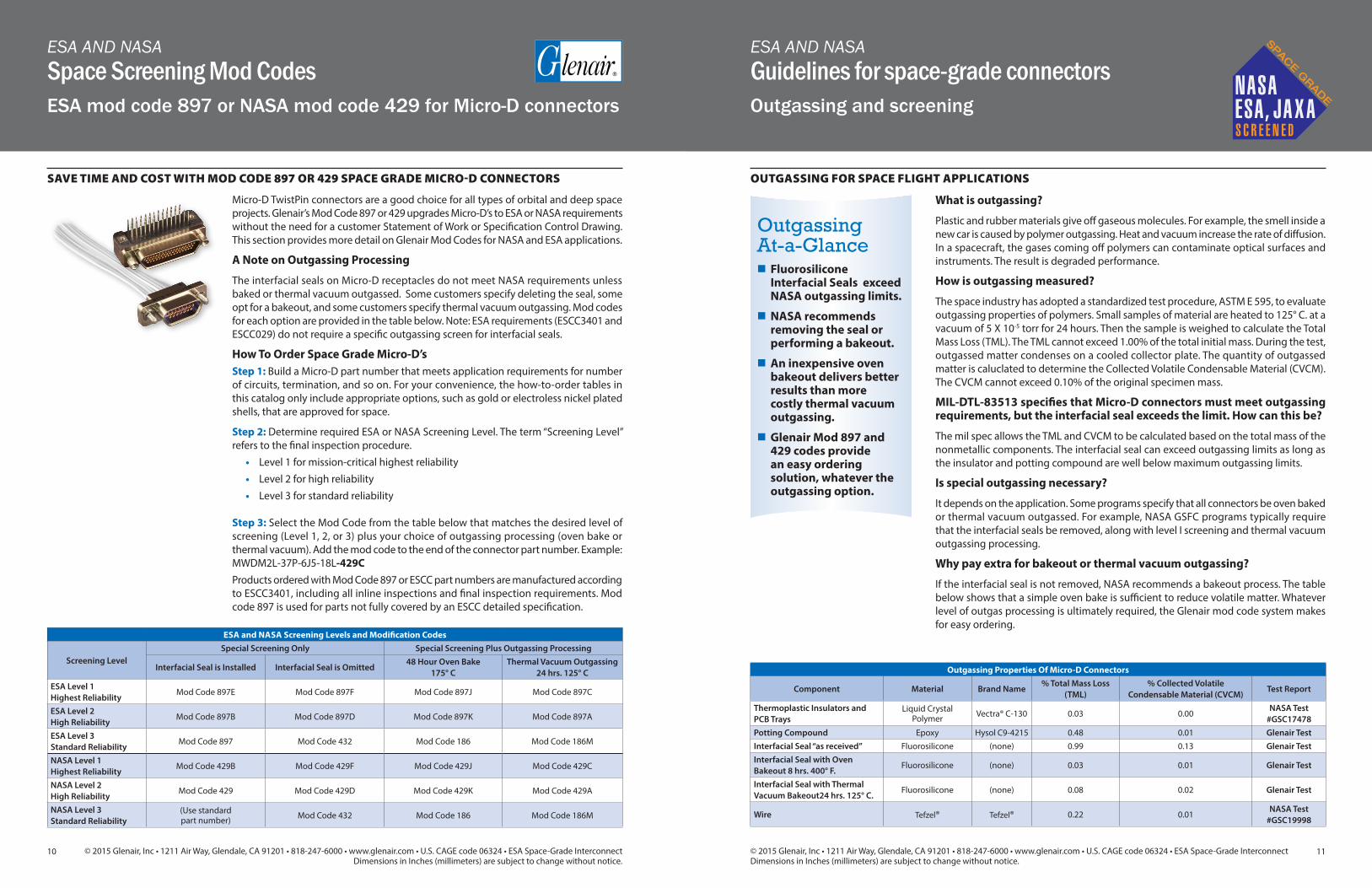
ESA AND NASAGuidelines for space-grade connectorsOutgassing and screening
ESA AND NASASpace Screening Mod CodesESA mod code 897 or NASA mod code 429 for Micro-D connectors
Micro‐D TwistPin connectors are a good choice for all types of orbital and deep space projects. Glenair’s Mod Code 897 or 429 upgrades Micro‐D’s to ESA or NASA requirements without the need for a customer Statement of Work or Specification Control Drawing. This section provides more detail on Glenair Mod Codes for NASA and ESA applications.
A Note on Outgassing Processing
The interfacial seals on Micro‐D receptacles do not meet NASA requirements unless baked or thermal vacuum outgassed. Some customers specify deleting the seal, some opt for a bakeout, and some customers specify thermal vacuum outgassing. Mod codes for each option are provided in the table below. Note: ESA requirements (ESCC3401 and ESCC029) do not require a specific outgassing screen for interfacial seals.
How To Order Space Grade Micro‐D’sStep 1: Build a Micro‐D part number that meets application requirements for number of circuits, termination, and so on. For your convenience, the how-to-order tables in this catalog only include appropriate options, such as gold or electroless nickel plated shells, that are approved for space.
Step 2: Determine required ESA or NASA Screening Level. The term “Screening Level” refers to the final inspection procedure.
• Level 1 for mission‐critical highest reliability• Level 2 for high reliability• Level 3 for standard reliability
Step 3: Select the Mod Code from the table below that matches the desired level of screening (Level 1, 2, or 3) plus your choice of outgassing processing (oven bake or thermal vacuum). Add the mod code to the end of the connector part number. Example: MWDM2L‐37P‐6J5‐18L‐429CProducts ordered with Mod Code 897 or ESCC part numbers are manufactured according to ESCC3401, including all inline inspections and final inspection requirements. Mod code 897 is used for parts not fully covered by an ESCC detailed specification.
SAVE TIME AND COST WITH MOD CODE 897 OR 429 SPACE GRADE MICRO-D CONNECTORS OUTGASSING FOR SPACE FLIGHT APPLICATIONS
ESA and NASA Screening Levels and Modification Codes
Screening LevelSpecial Screening Only Special Screening Plus Outgassing Processing
Interfacial Seal is Installed Interfacial Seal is Omitted48 Hour Oven Bake
175° CThermal Vacuum Outgassing
24 hrs. 125° CESA Level 1 Highest Reliability
Mod Code 897E Mod Code 897F Mod Code 897J Mod Code 897C
ESA Level 2 High Reliability
Mod Code 897B Mod Code 897D Mod Code 897K Mod Code 897A
ESA Level 3 Standard Reliability
Mod Code 897 Mod Code 432 Mod Code 186 Mod Code 186M
NASA Level 1 Highest Reliability
Mod Code 429B Mod Code 429F Mod Code 429J Mod Code 429C
NASA Level 2 High Reliability
Mod Code 429 Mod Code 429D Mod Code 429K Mod Code 429A
NASA Level 3 Standard Reliability
(Use standard part number) Mod Code 432 Mod Code 186 Mod Code 186M
Outgassing Properties Of Micro-D Connectors
Component Material Brand Name% Total Mass Loss
(TML)% Collected Volatile
Condensable Material (CVCM)Test Report
Thermoplastic Insulators and PCB Trays
Liquid Crystal Polymer Vectra® C-130 0.03 0.00
NASA Test #GSC17478
Potting Compound Epoxy Hysol C9-4215 0.48 0.01 Glenair TestInterfacial Seal “as received” Fluorosilicone (none) 0.99 0.13 Glenair TestInterfacial Seal with Oven Bakeout 8 hrs. 400° F.
Fluorosilicone (none) 0.03 0.01 Glenair Test
Interfacial Seal with Thermal Vacuum Bakeout24 hrs. 125° C.
Fluorosilicone (none) 0.08 0.02 Glenair Test
Wire Tefzel® Tefzel® 0.22 0.01NASA Test
#GSC19998
Outgassing At-a-Glance�n Fluorosilicone Interfacial Seals exceed NASA outgassing limits.
�n NASA recommends removing the seal or performing a bakeout.
�n An inexpensive oven bakeout delivers better results than more costly thermal vacuum outgassing.
�n Glenair Mod 897 and 429 codes provide an easy ordering solution, whatever the outgassing option.
What is outgassing?
Plastic and rubber materials give off gaseous molecules. For example, the smell inside a new car is caused by polymer outgassing. Heat and vacuum increase the rate of diffusion. In a spacecraft, the gases coming off polymers can contaminate optical surfaces and instruments. The result is degraded performance.
How is outgassing measured?
The space industry has adopted a standardized test procedure, ASTM E 595, to evaluate outgassing properties of polymers. Small samples of material are heated to 125° C. at a vacuum of 5 X 10⁻⁵ torr for 24 hours. Then the sample is weighed to calculate the Total Mass Loss (TML). The TML cannot exceed 1.00% of the total initial mass. During the test, outgassed matter condenses on a cooled collector plate. The quantity of outgassed matter is caluclated to determine the Collected Volatile Condensable Material (CVCM). The CVCM cannot exceed 0.10% of the original specimen mass.
MIL-DTL-83513 specifies that Micro-D connectors must meet outgassing requirements, but the interfacial seal exceeds the limit. How can this be?
The mil spec allows the TML and CVCM to be calculated based on the total mass of the nonmetallic components. The interfacial seal can exceed outgassing limits as long as the insulator and potting compound are well below maximum outgassing limits.
Is special outgassing necessary?
It depends on the application. Some programs specify that all connectors be oven baked or thermal vacuum outgassed. For example, NASA GSFC programs typically require that the interfacial seals be removed, along with level I screening and thermal vacuum outgassing processing.
Why pay extra for bakeout or thermal vacuum outgassing?
If the interfacial seal is not removed, NASA recommends a bakeout process. The table below shows that a simple oven bake is sufficient to reduce volatile matter. Whatever level of outgas processing is ultimately required, the Glenair mod code system makes for easy ordering.

1312 © 2015 Glenair, Inc • 1211 Air Way, Glendale, CA 91201 • 818-247-6000 • www.glenair.com • U.S. CAGE code 06324 • ESA Space-Grade InterconnectDimensions in Inches (millimeters) are subject to change without notice.
S C R E E N E D
NASAESA, JA X A
SPACE G
RADE
© 2015 Glenair, Inc • 1211 Air Way, Glendale, CA 91201 • 818-247-6000 • www.glenair.com • U.S. CAGE code 06324 • ESA Space-Grade InterconnectDimensions in Inches (millimeters) are subject to change without notice. Rev. 05.07.15
SPACE-GRADE INTERCONNECTNASA ScreeningMod Code -429, NASA screening according to EEE-INST-002
SPACE-GRADE INTERCONNECTESA ScreeningMod Code -897, ESA screening according to ESCC3401, paragraph 8.2 Lot Acceptance Testing
NASA SCREENINGNASA specification EEE-INST-002 (see figure 1) provides instructions on selecting, screening and qualifying parts for use on NASA GSFC space flight projects. Table 2C in the NASA spec contains specific inspection instructions for MIL-DTL-83513 connectors. These screening requirements exceed the standard mil spec inspection levels.
SCREENING LEVELSNASA defines three levels of screening: level 1 for highest reliability, level 2 for high reliability, and level 3 for standard reliability. Level 3 equates to standard M83513 Group A and B lot acceptance testing, and levels 1 and 2 call for additional testing.
ADDITIONAL SCREENING BY GLENAIRGlenair has test procedures that go beyond the letter of the NASA spec. Meeting NASA requirements means not only inspecting per EEE-INST-002, but also building parts in accordance with NASA Technical Standard NASA-STD-8739.4 “Crimping, Interconnecting Cables, Harnesses, and Wiring”. Glenair fully meets these requirements and has obtained NASA certification. Our extra inspection steps reflect the fact that pre-wired connectors not only require best practices on the assembly floor, but also require thorough final electrical and mechanical testing.
QUALIFICATION REQUIREMENTSQualification is not required if the manufacturer has performed qualification testing per MIL-DTL-83513. Qualification by similarity is usually invoked for those Micro-D’s not specifically covered by the mil spec.
ESA SCREENINGESA specification ESCC3401provides instructions on selecting, screening and qualifying parts for use on ESA space flight projects. Chart V in the ESA spec contains specific inspection instructions for ESCC3401-029 issue 10 (MIL-DTL-83513) connectors. These screening requirements exceed the standard mil spec inspection levels.
SCREENING LEVELSESA defines three levels of screening: level 1 for highest reliability, level 2 for high reliability, and level 3 for standard reliability. Level 3 equates to standard ESA3401 acceptance testing.
ADDITIONAL SCREENING BY GLENAIRGlenair has test procedures that go beyond the letter of the ESA spec. Meeting ESA requirements means not only inspecting per ESCC3401, but also building parts in accordance with ESA Technical Standard ESCC3401. Glenair fully meets these requirements. Our extra inspection steps reflect the fact that pre-wired connectors not only require best practices on the assembly floor, but also require thorough final electrical and mechanical testing.
QUALIFICATION REQUIREMENTSQualification is not necessarily required if the manufacturer has performed the LAT according to the ESCC3401 standard. Qualification by similarity is usually invoked for those connectors not specifically covered by the mil spec. Components ordered to ESCC P/Ns are manufactured and tested to fully comply to the applicable ESCC standard. Components ordered to Glenair P/Ns are manufactured and tested fully to the applicable Mil std. Both variants can be ordered with any level of ESA or NASA screening and/or removed or outgassed interfacial seals.
Due to the dynamic nature of this document, users are advised to check the http://nepp.nasa.gov website prior to every usage to obtain the latest document revision.
1.0 PURPOSE
The purpose of this document is to establish baseline criteria for selection, screening, qualification, and derating of EEE parts for use on NASA GSFC space flight projects. This document shall provide a mechanism to assure that appropriate parts are used in the fabrication of space hardware that will meet mission reliability objectives within budget constraints.
2.0 SCOPE
This document provides instructions for meeting three reliability levels of EEE parts requirements (see 6.0) based on mission needs. The terms “grade” and “level” are considered synonymous; i.e., a grade 1 part is consistent with reliability level 1. Levels of part reliability confidence decrease by reliability level, with level 1 being the highest reliability and level 3 the lowest. A reliability level 1 part has the highest level of manufacturing control and testing per military or DSCC specifications. Level 2 parts have reduced manufacturing control and testing. Level 3 Parts have no guaranteed reliability controls in the manufacturing process and no standardized testing requirements. The reliability of level 3 parts can vary significantly with each manufacturer, part type and LDC due to unreported and frequent changes in design, construction and materials.
GSFC projects and contractors shall incorporate this guideline into their Project EEE Parts Program.
3.0 DEFINITIONS
Screening. Screening tests are intended to remove nonconforming parts (parts with random defects that are likely to result in early failures, known as infant mortality) from an otherwise acceptable lot and thus increase confidence in the reliability of the parts selected for use.
Figure 1: Excerpt from NASA EEE-INST-002
Table 2: NASA Screening Requirements
Inspection/ Test NASA Level 1 NASA Level 2
Visual Inspection (3X magnification) 100% 100%
Mechanical 2 pcs. 2 pcs.
Voltage (DWV) 100% 2 pcs.
Insulation Resistance 2 pcs. 2 pcs.
Temperature Cycling 2 pcs. N/A
Low Level Contact Resistance 2 pcs. 2 pcs.
Mating Force 2 pcs. N/A
Solderability/Resistance to Soldering Heat 2 pcs. N/A
Notes: 1. NASA screening requirements from Table 2J of EEE-INST-002.
LAT and/or outgassing test if required
Summary of ESCC3401/ESCC3401-029 Test Requirements Included in Mod Code 897
MIL-DTL-83513
Requirement Description
Gold plating porosity and thickness
Shell: 0.7um minimum gold plating Contacts: 1.27um minimum gold over Cu.
N/A 1.27um gold over Ni
Crimp Capability Per ESA PSS 01-725 (per (P/O) Per MIL-STD-22520
Contact Capability per ESCC3401-029, para 4.3.3
Measurements Pick-up Drop weightWeight (g) 14 170 SamePin dia (mm) 0.582-0.587 0.559-0.564 Same
Insert depth 1.5 1.5Same/ Glenair standard prod. test
Dimensional inspection of contacts per ESCC3401, para 9.6
IAW ESA/SCC Basic Specification No. 20500 and the detailed Specification, to Inspection Level 2 an an Acceptance Quality Level of 1,0
100%/ Glenair standard prod. Test
Installation of Contacts IAW the Process Identification Document Same
Electrical Measurements per ESCC33401-029, Table II
Insulation resistance Min. 5000MOhm Min. 5000MOhm
Voltage Proof, Leakage Current Max. 2mA at 600Vrms 600Vrms
Mated Shell Conductivity No value N/A
Contact ResistanceLow level 6mOhm Rated current 5mOhm
28mOhm, incl. 6 inch AWG 26 wire
Mating Verification per ESCC3401, para 9.5
N/A, only applicable for circular connectors with integrated coupling mechanism. N/A
Magnetism Level per ESCC 3401-029, para. 4.2.2
N/APermeability shall not exceed 2.0u
Connector Dimensional Check per ESCC3401
Physical dimensions match ESCC detailed specification ESCC3401-029 and ESCC 3401-041
Acc. To MIL-DTL-83513
Marking per ESCC3401, para 4.4 IAW ESA/SCC Basic Specification 21700 N/A
External Visual Inspection/Visual Inspection of Piece Parts per ESCC3401, ¶ 9.7
IAW ESA/SCC Basic Specification No.20500• External surfaces - free of foreign particles and
contamination. No evidence of corrosion, peeling of finish/plating nor of any holes or cracks.
• Marking - complies with detail spec and shows no damage or degradation
• Solder joints - Surface of the solder is smooth and clean. No Evidence of cracks, voids or holes. Structure of the soldered part is visible. Complete solder flow or coverage. No Balling or spherical appearance of the solder. No Evidence of foreign materials encapsulated in the solder.
• Materials and construction and dimensions per relevant ESCC Detail Spec for the specific part.
Acc. to MIL-DTL-83513

1514
AA
© 2015 Glenair, Inc • 1211 Air Way, Glendale, CA 91201 • 818-247-6000 • www.glenair.com • U.S. CAGE code 06324 • ESA Space-Grade InterconnectDimensions in Inches (millimeters) are subject to change without notice.
© 2015 Glenair, Inc • 1211 Air Way, Glendale, CA 91201 • 818-247-6000 • www.glenair.com • U.S. CAGE code 06324 • ESA Space-Grade InterconnectDimensions in Inches (millimeters) are subject to change without notice.
S C R E E N E D
NASAESA, JA X A
SPACE G
RADE
SPACE-GRADE MICRO-D CONNECTORSMWDM Micro-D pigtail wire connectorsESA to Glenair Part Number cross-reference
SPACE-GRADE MICRO-D CONNECTORSMWDM Micro-D pigtail wire connectorsto ESCC3401-029 and MIL-DTL-83513
How To Order Insulated Wire Connectors
Sample Part Number MWDM 2 L –15 P 6 G 1 –20 -897B
Series MWDM Glenair Micro-D
Shell Material and FinishAluminum Shell2 - Nickel 5 - Gold
Insulator Material L - LCP - 30% Glass-Filled Liquid Crystal Polymer
Contact Layout 9, 15, 21, 25, 31, 37, 51
Contact Type P - Pin S - Socket
Wire Gage (AWG) 5 - #25 (uninsulated wire only) 6 - #26 8 - #28
Wire TypeE – NEMA HP3-EB 600 VRMS Type E M16878/4 (TFE) G - ESCC3901-002 56B (26 AWG only)M - ESCC3901-013 C - Uninsulated solid wires (length 25.4mm)
Wire Color 1 – White 2 – Natural (for G type wire only) 3 = (Gold-plated solid copper wire only)
Wire Length Inches 1 - (25.4mm) 20 - (508mm) 36 - (914mm) 158 - (4000mm)
Screening Mod Codes -429 (NASA) -897 (ESA) Omit for no screening required (see table below)
DIMENSIONS / WEIGHTSDimensions and other options are available in the Glenair High-Performance Micro-D Connectors and Cables catalog, page B-10. Weights according to ESCC 3401-029.
SCREENINGAdd Mod Code -897 after the part number for ESA screening.Add Mod Code -429 for NASA EEE-INS-002 screening.
Mod code 897 applied to all connector part numbers. Complies with the test and screening requirements of ESCC 3401-029 level B and ESCC 3401
FEATURES
�n High-quality TwistPin contact system
�n MIL-DTL-83513 qualified
�n Available with ESCC3901-002 56B and ESCC3901 013 wire
�n Project-specific wired assemblies available
�n Screened to ESA or NASA operational standards
�n Manufactured in the EU
Micro-D 9 Way Pin Micro-D 9 Way SocketESA Basic Number Variant no. Glenair Part Number ESA Basic Number Variant no. Glenair Part Number
ECSS340102901B 9PFR112 MWDM 2L 9P 6M1 20 - 897 ECSS340102901B 9SFR112 MWDM 2L 9S 6M1 20 - 897ECSS340102902B 9PFR112 MWDM 5L 9P 6M1 20 - 897 ECSS340102902B 9SFR112 MWDM 5L 9S 6M1 20 - 897ECSS340102901B 9PFR112A MWDM 2L 9P 6G2 20 - 897 ECSS340102901B 9SFR112A MWDM 2L 9S 6G2 20 - 897ECSS340102902B 9PFR112A MWDM 5L 9P 6G2 20 - 897 ECSS340102902B 9SFR112A MWDM 5L 9S 6G2 20 - 897ECSS340102901B 9PFR113 MWDM 2L 9P 6M1 36 - 897 ECSS340102901B 9SFR113 MWDM 2L 9S 6M1 36 - 897ECSS340102902B 9PFR113 MWDM 5L 9P 6M1 36 - 897 ECSS340102902B 9SFR113 MWDM 5L 9S 6M1 36 - 897ECSS340102901B 9PFR113A MWDM 2L 9P 6G2 36 - 897 ECSS340102901B 9SFR113A MWDM 2L 9S 6G2 36 - 897ECSS340102902B 9PFR113A MWDM 5L 9P 6G2 36 - 897 ECSS340102902B 9SFR113A MWDM 5L 9S 6G2 36 - 897ECSS340102901B 9PFR123 MWDM 2L 9P 6M1 158 - 897 ECSS340102901B 9SFR123 MWDM 2L 9S 6M1 158 - 897ECSS340102902B 9PFR123 MWDM 5L 9P 6M1 158 - 897 ECSS340102902B 9SFR123 MWDM 5L 9S 6M1 158 - 897ECSS340102901B 9PFR123A MWDM 2L 9P 6G2 158 - 897 ECSS340102901B 9SFR123A MWDM 2L 9S 6G2 158 - 897ECSS340102902B 9PFR123A MWDM 5L 9P 6G2 158 - 897 ECSS340102902B 9SFR123A MWDM 5L 9S 6G2 158 - 897ECSS340102901B 9PFR114 MWDM 2L 9P 8M1 20 - 897 ECSS340102901B 9SFR114 MWDM 2L 9S 8M1 20 - 897ECSS340102902B 9PFR114 MWDM 5L 9P 8M1 20 - 897 ECSS340102902B 9SFR114 MWDM 5L 9S 8M1 20 - 897ECSS340102901B 9PFR115 MWDM 2L 9P 8M1 36 - 897 ECSS340102901B 9SFR115 MWDM 2L 9S 8M1 36 - 897ECSS340102902B 9PFR115 MWDM 5L 9P 8M1 36 - 897 ECSS340102902B 9SFR115 MWDM 5L 9S 8M1 36 - 897ECSS340102901B 9PFR116 MWDM 2L 9P 5C3 1 - 897 ECSS340102901B 9SFR116 MWDM 2L 9S 5C3 1 - 897ECSS340102902B 9PFR116 MWDM 5L 9P 5C3 1 - 897 ECSS340102902B 9SFR116 MWDM 5L 9S 5C3 1 - 897
Micro-D 15 Way Pin Micro-D 15 Way SocketESA Basic Number Variant no. Glenair Part Number ESA Basic Number Variant no. Glenair Part Number
ECSS340102901B 15PFR112 MWDM 2L 15P 6M1 20 - 897 ECSS340102901B 15SFR112 MWDM 2L 15S 6M1 20 - 897ECSS340102902B 15PFR112 MWDM 5L 15P 6M1 20 - 897 ECSS340102902B 15SFR112 MWDM 5L 15S 6M1 20 - 897ECSS340102901B 15PFR112A MWDM 2L 15P 6G2 20 - 897 ECSS340102901B 15SFR112A MWDM 2L 15S 6G2 20 - 897ECSS340102902B 15PFR112A MWDM 5L 15P 6G2 20 - 897 ECSS340102902B 15SFR112A MWDM 5L 15S 6G2 20 - 897ECSS340102901B 15PFR113 MWDM 2L 15P 6M1 36 - 897 ECSS340102901B 15SFR113 MWDM 2L 15S 6M1 36 - 897ECSS340102902B 15PFR113 MWDM 5L 15P 6M1 36 - 897 ECSS340102902B 15SFR113 MWDM 5L 15S 6M1 36 - 897ECSS340102901B 15PFR113A MWDM 2L 15P 6G2 36 - 897 ECSS340102901B 15SFR113A MWDM 2L 15S 6G2 36 - 897ECSS340102902B 15PFR113A MWDM 5L 15P 6G2 36 - 897 ECSS340102902B 15SFR113A MWDM 5L 15S 6G2 36 - 897ECSS340102901B 15PFR123 MWDM 2L 15P 6M1 158 - 897 ECSS340102901B 15SFR123 MWDM 2L 15S 6M1 158 - 897ECSS340102902B 15PFR123 MWDM 5L 15P 6M1 158 - 897 ECSS340102902B 15SFR123 MWDM 5L 15S 6M1 158 - 897ECSS340102901B 15PFR123A MWDM 2L 15P 6G2 158 - 897 ECSS340102901B 15SFR123A MWDM 2L 15S 6G2 158 - 897ECSS340102902B 15PFR123A MWDM 5L 15P 6G2 158 - 897 ECSS340102902B 15SFR123A MWDM 5L 15S 6G2 158 - 897ECSS340102901B 15PFR114 MWDM 2L 15P 8M1 20 - 897 ECSS340102901B 15SFR114 MWDM 2L 15S 8M1 20 - 897ECSS340102902B 15PFR114 MWDM 5L 15P 8M1 20 - 897 ECSS340102902B 15SFR114 MWDM 5L 15S 8M1 20 - 897ECSS340102901B 15PFR115 MWDM 2L 15P 8M1 36 - 897 ECSS340102901B 15SFR115 MWDM 2L 15S 8M1 36 - 897ECSS340102902B 15PFR115 MWDM 5L 15P 8M1 36 - 897 ECSS340102902B 15SFR115 MWDM 5L 15S 8M1 36 - 897ECSS340102901B 15PFR116 MWDM 2L 15P 5C3 1 - 897 ECSS340102901B 15SFR116 MWDM 2L 15S 5C3 1 - 897ECSS340102902B 15PFR116 MWDM 5L 15P 5C3 1 - 897 ECSS340102902B 15SFR116 MWDM 5L 15S 5C3 1 - 897
ESA and NASA Screening Levels and Modification Codes
Screening LevelSpecial Screening Only Special Screening Plus Outgassing Processing
Interfacial Seal is Installed Interfacial Seal is Deleted 48 Hour Oven Bake 175° C Thermal Vacuum Outgassing 24 hrs. 125° CESA Level 1 Highest Reliability Mod Code 897E Mod Code 897F Mod Code 897J Mod Code 897C
ESA Level 2 High Reliability Mod Code 897B Mod Code 897D Mod Code 897K Mod Code 897A
ESA Level 3 Standard Reliability Mod Code 897 Mod Code 432 Mod Code 186 Mod Code 186M
NASA Level 1 Highest Reliability Mod Code 429B Mod Code 429F Mod Code 429J Mod Code 429C
NASA Level 2 High Reliability Mod Code 429 Mod Code 429D Mod Code 429K Mod Code 429A
NASA Level 3 Standard Reliability
(Use standard part number) Mod Code 432 Mod Code 186 Mod Code 186M

1716
AA
© 2015 Glenair, Inc • 1211 Air Way, Glendale, CA 91201 • 818-247-6000 • www.glenair.com • U.S. CAGE code 06324 • ESA Space-Grade InterconnectDimensions in Inches (millimeters) are subject to change without notice.
© 2015 Glenair, Inc • 1211 Air Way, Glendale, CA 91201 • 818-247-6000 • www.glenair.com • U.S. CAGE code 06324 • ESA Space-Grade InterconnectDimensions in Inches (millimeters) are subject to change without notice.
S C R E E N E D
NASAESA, JA X A
SPACE G
RADE
SPACE-GRADE MICRO-D CONNECTORSMWDM Micro-D pigtail wire connectorsESA to Glenair Part Number cross-reference
SPACE-GRADE MICRO-D CONNECTORSMWDM Micro-D pigtail wire connectorsESA to Glenair Part Number cross-reference
Micro-D 21 Way Pin Micro-D 21 Way SocketESA Basic Number Variant no. Glenair Part Number ESA Basic Number Variant no. Glenair Part Number
ECSS340102901B 21PFR112 MWDM 2L 21P 6M1 20 - 897 ECSS340102901B 21SFR112 MWDM 2L 21S 6M1 20 - 897ECSS340102902B 21PFR112 MWDM 5L 21P 6M1 20 - 897 ECSS340102902B 21SFR112 MWDM 5L 21S 6M1 20 - 897ECSS340102901B 21PFR112A MWDM 2L 21P 6G2 20 - 897 ECSS340102901B 21SFR112A MWDM 2L 21S 6G2 20 - 897ECSS340102902B 21PFR112A MWDM 5L 21P 6G2 20 - 897 ECSS340102902B 21SFR112A MWDM 5L 21S 6G2 20 - 897ECSS340102901B 21PFR113 MWDM 2L 21P 6M1 36 - 897 ECSS340102901B 21SFR113 MWDM 2L 21S 6M1 36 - 897ECSS340102902B 21PFR113 MWDM 5L 21P 6M1 36 - 897 ECSS340102902B 21SFR113 MWDM 5L 21S 6M1 36 - 897ECSS340102901B 21PFR113A MWDM 2L 21P 6G2 36 - 897 ECSS340102901B 21SFR113A MWDM 2L 21S 6G2 36 -897ECSS340102902B 21PFR113A MWDM 5L 21P 6G2 36 - 897 ECSS340102902B 21SFR113A MWDM 5L 21S 6G2 36 - 897ECSS340102901B 21PFR123 MWDM 2L 21P 6M1 158 - 897 ECSS340102901B 21SFR123 MWDM 2L 21S 6M1 158 - 897ECSS340102902B 21PFR123 MWDM 5L 21P 6M1 158 - 897 ECSS340102902B 21SFR123 MWDM 5L 21S 6M1 158 - 897ECSS340102901B 21PFR123A MWDM 2L 21P 6G2 158 - 897 ECSS340102901B 21SFR123A MWDM 2L 21S 6G2 158 - 897ECSS340102902B 21PFR123A MWDM 5L 21P 6G2 158 - 897 ECSS340102902B 21SFR123A MWDM 5L 21S 6G2 158 - 897ECSS340102901B 21PFR114 MWDM 2L 21P 8M1 20 - 897 ECSS340102901B 21SFR114 MWDM 2L 21S 8M1 20 - 897ECSS340102902B 21PFR114 MWDM 5L 21P 8M1 20 - 897 ECSS340102902B 21SFR114 MWDM 5L 21S 8M1 20 - 897ECSS340102901B 21PFR115 MWDM 2L 21P 8M1 36 - 897 ECSS340102901B 21SFR115 MWDM 2L 21S 8M1 36 - 897ECSS340102902B 21PFR115 MWDM 5L 21P 8M1 36 - 897 ECSS340102902B 21SFR115 MWDM 5L 21S 8M1 36 - 897ECSS340102901B 21PFR116 MWDM 2L 21P 5C3 1 - 897 ECSS340102901B 21SFR116 MWDM 2L 21S 5C3 1 - 897ECSS340102902B 21PFR116 MWDM 5L 21P 5C3 1 - 897 ECSS340102902B 21SFR116 MWDM 5L 21S 5C3 1 - 897
Micro-D 25 Way Pin Micro-D 25 Way SocketESA Basic Number Variant no. Glenair Part Number ESA Basic Number Variant no. Glenair Part Number
ECSS340102901B 25PFR112 MWDM 2L 25P 6M1 20 - 897 ECSS340102901B 25SFR112 MWDM 2L 25S 6M1 20 - 897ECSS340102902B 25PFR112 MWDM 5L 25P 6M1 20 - 897 ECSS340102902B 25SFR112 MWDM 5L 25S 6M1 20 - 897ECSS340102901B 25PFR112A MWDM 2L 25P 6G2 20 - 897 ECSS340102901B 25SFR112A MWDM 2L 25S 6G2 20 - 897ECSS340102902B 25PFR112A MWDM 5L 25P 6G2 20 - 897 ECSS340102902B 25SFR112A MWDM 5L 25S 6G2 20 - 897ECSS340102901B 25PFR113 MWDM 2L 25P 6M1 36 - 897 ECSS340102901B 25SFR113 MWDM 2L 25S 6M1 36 - 897ECSS340102902B 25PFR113 MWDM 5L 25P 6M1 36 - 897 ECSS340102902B 25SFR113 MWDM 5L 25S 6M1 36 - 897ECSS340102901B 25PFR113A MWDM 2L 25P 6G2 36 - 897 ECSS340102901B 25SFR113A MWDM 2L 25S 6G2 36 - 897ECSS340102902B 25PFR113A MWDM 5L 25P 6G2 36 - 897 ECSS340102902B 25SFR113A MWDM 5L 25S 6G2 36 - 897ECSS340102901B 25PFR123 MWDM 2L 25P 6M1 158 - 897 ECSS340102901B 25SFR123 MWDM 2L 25S 6M1 158 - 897ECSS340102902B 25PFR123 MWDM 5L 25P 6M1 158 - 897 ECSS340102902B 25SFR123 MWDM 5L 25S 6M1 158 - 897ECSS340102901B 25PFR123A MWDM 2L 25P 6G2 158 - 897 ECSS340102901B 25SFR123A MWDM 2L 25S 6G2 158 - 897ECSS340102902B 25PFR123A MWDM 5L 25P 6G2 158 - 897 ECSS340102902B 25SFR123A MWDM 5L 25S 6G2 158 - 897ECSS340102901B 25PFR114 MWDM 2L 25P 8M1 20 - 897 ECSS340102901B 25SFR114 MWDM 2L 25S 8M1 20 - 897ECSS340102902B 25PFR114 MWDM 5L 25P 8M1 20 - 897 ECSS340102902B 25SFR114 MWDM 5L 25S 8M1 20 - 897ECSS340102901B 25PFR115 MWDM 2L 25P 8M1 36 - 897 ECSS340102901B 25SFR115 MWDM 2L 25S 8M1 36 - 897ECSS340102902B 25PFR115 MWDM 5L 25P 8M1 36 - 897 ECSS340102902B 25SFR115 MWDM 5L 25S 8M1 36 - 897ECSS340102901B 25PFR116 MWDM 2L 25P 5C3 1 - 897 ECSS340102901B 25SFR116 MWDM 2L 25S 5C3 1 - 897ECSS340102902B 25PFR116 MWDM 5L 25P 5C3 1 - 897 ECSS340102902B 25SFR116 MWDM 5L 25S 5C3 1 - 897
Micro-D 31 Way Pin Micro-D 31 Way SocketESA Basic Number Variant no. Glenair Part Number ESA Basic Number Variant no. Glenair Part Number
ECSS340102901B 31PFR112 MWDM 2L 31P 6M1 20 - 897 ECSS340102901B 31SFR112 MWDM 2L 31S 6M1 20 - 897ECSS340102902B 31PFR112 MWDM 5L 31P 6M1 20 - 897 ECSS340102902B 31SFR112 MWDM 5L 31S 6M1 20 - 897ECSS340102901B 31PFR112A MWDM 2L 31P 6G2 20 - 897 ECSS340102901B 31SFR112A MWDM 2L 31S 6G2 20 - 897ECSS340102902B 31PFR112A MWDM 5L 31P 6G2 20 - 897 ECSS340102902B 31SFR112A MWDM 5L 31S 6G2 20 - 897ECSS340102901B 31PFR113 MWDM 2L 31P 6M1 36 - 897 ECSS340102901B 31SFR113 MWDM 2L 31S 6M1 36 - 897ECSS340102902B 31PFR113 MWDM 5L 31P 6M1 36 - 897 ECSS340102902B 31SFR113 MWDM 5L 31S 6M1 36 - 897ECSS340102901B 31PFR113A MWDM 2L 31P 6G2 36 - 897 ECSS340102901B 31SFR113A MWDM 2L 31S 6G2 36 - 897ECSS340102902B 31PFR113A MWDM 5L 31P 6G2 36 - 897 ECSS340102902B 31SFR113A MWDM 5L 31S 6G2 36 - 897ECSS340102901B 31PFR123 MWDM 2L 31P 6M1 158 - 897 ECSS340102901B 31SFR123 MWDM 2L 31S 6M1 158 - 897ECSS340102902B 31PFR123 MWDM 5L 31P 6M1 158 - 897 ECSS340102902B 31SFR123 MWDM 5L 31S 6M1 158 - 897ECSS340102901B 31PFR123A MWDM 2L 31P 6G2 158 - 897 ECSS340102901B 31SFR123A MWDM 2L 31S 6G2 158 - 897ECSS340102902B 31PFR123A MWDM 5L 31P 6G2 158 - 897 ECSS340102902B 31SFR123A MWDM 5L 31S 6G2 158 - 897ECSS340102901B 31PFR114 MWDM 2L 31P 8M1 20 - 897 ECSS340102901B 31SFR114 MWDM 2L 31S 8M1 20 - 897ECSS340102902B 31PFR114 MWDM 5L 31P 8M1 20 - 897 ECSS340102902B 31SFR114 MWDM 5L 31S 8M1 20 - 897ECSS340102901B 31PFR115 MWDM 2L 31P 8M1 36 - 897 ECSS340102901B 31SFR115 MWDM 2L 31S 8M1 36 - 897ECSS340102902B 31PFR115 MWDM 5L 31P 8M1 36 - 897 ECSS340102902B 31SFR115 MWDM 5L 31S 8M1 36 - 897ECSS340102901B 31PFR116 MWDM 2L 31P 5C3 1 - 897 ECSS340102901B 31SFR116 MWDM 2L 31S 5C3 1 - 897ECSS340102902B 31PFR116 MWDM 5L 31P 5C3 1 - 897 ECSS340102902B 31SFR116 MWDM 5L 31S 5C3 1 - 897
Micro-D 37 Way Pin Micro-D 37 Way SocketESA Basic Number Variant no. Glenair Part Number ESA Basic Number Variant no. Glenair Part Number
ECSS340102901B 37PFR112 MWDM 2L 37P 6M1 20 - 897 ECSS340102901B 37SFR112 MWDM 2L 37S 6M1 20 - 897ECSS340102902B 37PFR112 MWDM 5L 37P 6M1 20 - 897 ECSS340102902B 37SFR112 MWDM 5L 37S 6M1 20 - 897ECSS340102901B 37PFR112A MWDM 2L 37P 6G2 20 - 897 ECSS340102901B 37SFR112A MWDM 2L 37S 6G2 20 - 897ECSS340102902B 37PFR112A MWDM 5L 37P 6G2 20 - 897 ECSS340102902B 37SFR112A MWDM 5L 37S 6G2 20 - 897ECSS340102901B 37PFR113 MWDM 2L 37P 6M1 36 - 897 ECSS340102901B 37SFR113 MWDM 2L 37S 6M1 36 - 897ECSS340102902B 37PFR113 MWDM 5L 37P 6M1 36 - 897 ECSS340102902B 37SFR113 MWDM 5L 37S 6M1 36 - 897ECSS340102901B 37PFR113A MWDM 2L 37P 6G2 36 - 897 ECSS340102901B 37SFR113A MWDM 2L 37S 6G2 36 - 897ECSS340102902B 37PFR113A MWDM 5L 37P 6G2 36 - 897 ECSS340102902B 37SFR113A MWDM 5L 37S 6G2 36 - 897ECSS340102901B 37PFR123 MWDM 2L 37P 6M1 158 - 897 ECSS340102901B 37SFR123 MWDM 2L 37S 6M1 158 - 897ECSS340102902B 37PFR123 MWDM 5L 37P 6M1 158 - 897 ECSS340102902B 37SFR123 MWDM 5L 37S 6M1 158 - 897ECSS340102901B 37PFR123A MWDM 2L 37P 6G2 158 - 897 ECSS340102901B 37SFR123A MWDM 2L 37S 6G2 158 - 897ECSS340102902B 37PFR123A MWDM 5L 37P 6G2 158 - 897 ECSS340102902B 37SFR123A MWDM 5L 37S 6G2 158 - 897ECSS340102901B 37PFR114 MWDM 2L 37P 8M1 20 - 897 ECSS340102901B 37SFR114 MWDM 2L 37S 8M1 20 - 897ECSS340102902B 37PFR114 MWDM 5L 37P 8M1 20 - 897 ECSS340102902B 37SFR114 MWDM 5L 37S 8M1 20 - 897ECSS340102901B 37PFR115 MWDM 2L 37P 8M1 36 - 897 ECSS340102901B 37SFR115 MWDM 2L 37S 8M1 36 - 897ECSS340102902B 37PFR115 MWDM 5L 37P 8M1 36 - 897 ECSS340102902B 37SFR115 MWDM 5L 37S 8M1 36 - 897ECSS340102901B 37PFR116 MWDM 2L 37P 5C3 1 - 897 ECSS340102901B 37SFR116 MWDM 2L 37S 5C3 1 - 897ECSS340102902B 37PFR116 MWDM 5L 37P 5C3 1 - 897 ECSS340102902B 37SFR116 MWDM 5L 37S 5C3 1 - 897
Mod code 897 applied to all connector part numbers. Complies with the test and screening requirements of ESCC 3401-029 level B and ESCC 3401Mod code 897 applied to all connector part numbers. Complies with the test and screening requirements of ESCC 3401-029 level B and ESCC 3401

1918
AA
© 2015 Glenair, Inc • 1211 Air Way, Glendale, CA 91201 • 818-247-6000 • www.glenair.com • U.S. CAGE code 06324 • ESA Space-Grade InterconnectDimensions in Inches (millimeters) are subject to change without notice.
© 2015 Glenair, Inc • 1211 Air Way, Glendale, CA 91201 • 818-247-6000 • www.glenair.com • U.S. CAGE code 06324 • ESA Space-Grade InterconnectDimensions in Inches (millimeters) are subject to change without notice.
S C R E E N E D
NASAESA, JA X A
SPACE G
RADE
SPACE-GRADE MICRO-D CONNECTORSMWDM Micro-D solder cup connectorsto ESCC3401-029 and MIL-DTL-83513
SPACE-GRADE MICRO-D CONNECTORSMWDM Micro-D pigtail wire connectorsESA to Glenair Part Number cross-reference
Micro-D 51 Way Pin Micro-D 51 Way SocketESA Basic Number Variant no. Glenair Part Number ESA Basic Number Variant no. Glenair Part Number
ECSS340102901B 51PFR112 MWDM 2L 51P 6M1 20 - 897 ECSS340102901B 51SFR112 MWDM 2L 51S 6M1 20 - 897ECSS340102902B 51PFR112 MWDM 5L 51P 6M1 20 - 897 ECSS340102902B 51SFR112 MWDM 5L 51S 6M1 20 - 897ECSS340102901B 51PFR112A MWDM 2L 51P 6G2 20 - 897 ECSS340102901B 51SFR112A MWDM 2L 51S 6G2 20 - 897ECSS340102902B 51PFR112A MWDM 5L 51P 6G2 20 - 897 ECSS340102902B 51SFR112A MWDM 5L 51S 6G2 20 - 897ECSS340102901B 51PFR113 MWDM 2L 51P 6M1 36 - 897 ECSS340102901B 51SFR113 MWDM 2L 51S 6M1 36 - 897ECSS340102902B 51PFR113 MWDM 5L 51P 6M1 36 - 897 ECSS340102902B 51SFR113 MWDM 5L 51S 6M1 36 - 897ECSS340102901B 51PFR113A MWDM 2L 51P 6G2 36 - 897 ECSS340102901B 51SFR113A MWDM 2L 51S 6G2 36 - 897ECSS340102902B 51PFR113A MWDM 5L 51P 6G2 36 - 897 ECSS340102902B 51SFR113A MWDM 5L 51S 6G2 36 - 897ECSS340102901B 51PFR123 MWDM 2L 51P 6M1 158 - 897 ECSS340102901B 51SFR123 MWDM 2L 51S 6M1 158 - 897ECSS340102902B 51PFR123 MWDM 5L 51P 6M1 158 - 897 ECSS340102902B 51SFR123 MWDM 5L 51S 6M1 158 - 897ECSS340102901B 51PFR123A MWDM 2L 51P 6G2 158 - 897 ECSS340102901B 51SFR123A MWDM 2L 51S 6G2 158 - 897ECSS340102902B 51PFR123A MWDM 5L 51P 6G2 158 - 897 ECSS340102902B 51SFR123A MWDM 5L 51S 6G2 158 - 897ECSS340102901B 51PFR114 MWDM 2L 51P 8M1 20 - 897 ECSS340102901B 51SFR114 MWDM 2L 51S 8M1 20 - 897ECSS340102902B 51PFR114 MWDM 5L 51P 8M1 20 - 897 ECSS340102902B 51SFR114 MWDM 5L 51S 8M1 20 - 897ECSS340102901B 51PFR115 MWDM 2L 51P 8M1 36 - 897 ECSS340102901B 51SFR115 MWDM 2L 51S 8M1 36 - 897ECSS340102902B 51PFR115 MWDM 5L 51P 8M1 36 - 897 ECSS340102902B 51SFR115 MWDM 5L 51S 8M1 36 - 897ECSS340102901B 51PFR116 MWDM 2L 51P 5C3 1 - 897 ECSS340102901B 51SFR116 MWDM 2L 51S 5C3 1 - 897ECSS340102902B 51PFR116 MWDM 5L 51P 5C3 1 - 897 ECSS340102902B 51SFR116 MWDM 5L 51S 5C3 1 - 897
How To Order Solder Cup Connectors
Sample Part Number MWDM 2 L –15 P S B -897B
Series MWDM Glenair Micro-D
Shell Material and FinishAluminum Shell2 - Nickel 5 - Gold
Insulator Material L - LCP - 30% Glass-Filled Liquid Crystal Polymer
Contact Layout 9, 15, 21, 25, 31, 37 Cavities
Contact Type P - Pin S - Socket
Termination Type S - Solder Cup (Size #26 solder cup contacts)
Hardware B - No hardware (ordered separately, see next page)
Screening Mod Codes -429 (NASA) -897 (ESA) Omit for no screening required (see table below)
DIMENSIONS / WEIGHTSDimensions and other options are available in the Glenair High-Performance Micro-D Connectors and Cables catalog, page B-8. Weights according to ESCC 3401-029.
SCREENINGAdd Mod Code -897 after the part number for ESA screening.Add Mod Code -429 for NASA EEE-INS-002 screening.
FEATURES
�n High-quality TwistPin contact system
�n MIL-DTL-83513 qualified
�n Process and control according to ESCC3401-071 and 3401-029
�n Screened to ESA or NASA operational standards
�n Manufactured in the EU
Mod code 897 applied to all connector part numbers. Complies with the test and screening requirements of ESCC 3401-029 level B and ESCC 3401
ESA and NASA Screening Levels and Modification Codes
Screening LevelSpecial Screening Only Special Screening Plus Outgassing Processing
Interfacial Seal is Installed Interfacial Seal is Deleted 48 Hour Oven Bake 175° C Thermal Vacuum Outgassing 24 hrs. 125° CESA Level 1 Highest Reliability Mod Code 897E Mod Code 897F Mod Code 897J Mod Code 897C
ESA Level 2 High Reliability Mod Code 897B Mod Code 897D Mod Code 897K Mod Code 897A
ESA Level 3 Standard Reliability Mod Code 897 Mod Code 432 Mod Code 186 Mod Code 186M
NASA Level 1 Highest Reliability Mod Code 429B Mod Code 429F Mod Code 429J Mod Code 429C
NASA Level 2 High Reliability Mod Code 429 Mod Code 429D Mod Code 429K Mod Code 429A
NASA Level 3 Standard Reliability
(Use standard part number) Mod Code 432 Mod Code 186 Mod Code 186M

2120
AA
© 2015 Glenair, Inc • 1211 Air Way, Glendale, CA 91201 • 818-247-6000 • www.glenair.com • U.S. CAGE code 06324 • ESA Space-Grade InterconnectDimensions in Inches (millimeters) are subject to change without notice.
© 2015 Glenair, Inc • 1211 Air Way, Glendale, CA 91201 • 818-247-6000 • www.glenair.com • U.S. CAGE code 06324 • ESA Space-Grade InterconnectDimensions in Inches (millimeters) are subject to change without notice.
S C R E E N E D
NASAESA, JA X A
SPACE G
RADE
SPACE-GRADE MICRO-D CONNECTOR HARDWAREMWDM Micro-D hardware for pigtail wire and solder cup connectorsto ESCC3901-032
SPACE-GRADE MICRO-D CONNECTOR HARDWAREMWDM Micro-D hardware for pigtail wire and solder cup connectorsto ESCC3901-032
Part Number
Jackscrew Type
Thread Size ConfigurationRecommended
Max.TorqueMax. Weight In Grams (2 Kits)
179-013-1S Slot Head #2-56 UNC Figure 1 2.5 inch-pounds 1.0
Figure 1C Clip for Size 9 - 69 Pin Micro-D
.130 (3.3)
#2-56 UNC
.205 (5.21) .135 (3.4) REF
NUTWASHER
.086 (2.2)-56UNC-2B
.086 (2.2)-56UNC-2A
.190 / .185(4.8 / 4.7)
.072 (1.8)MAX
.026 (0.7)MAX
.154 (3.9) HEX
A
.125 (3.2)HEX
.088 (2.2)MAX
Figure 1#2-56 Jackpost
TYPE 08 JACKPOST KITS
Standard kits for installation on all standard Micro-D connectors. Each kit contains two jackposts, two hex nuts and two lockwashers.
TYPE 09 JACKPOST KITS FOR REAR-MOUNTED CONNECTORS
For rear panel mounted connectors.These round, slotted posts accommodate panel thickness from .031 inches (0.8 mm.) to .125 inches (3.2 mm.).
ESA PART NO. TRANSLATED TO GLENAIR EQUIVALENT PART NUMBER
TYPE 07 C-CLIP JACKSCREW KITS
C Clip Jackscrew Kits offer an alternative to e-ring jackscrew kits. The c clip fits over the flange and, unlike e-rings, cannot be dislodged in handling or use. Order Two Kits Per Connector. Each kit consists of one jackscrew and one c clip. The clip is made from 17-7PH spring temper stainless steel. The jackscrew is made from 125 KPSI tensile strength stainless steel, passivated. Note: The magnetic permeability of the c clip exceeds the 2.0 µ maximum of MIL-DTL-83513.
Connector Sizes
(THDS)
Glenair Part Number
A LengthFigureIn.
± .015mm.± 0.4
9 — 51 080-00-00-100 .475 12.1 Figure 1
NUTLOCKWASHER
.086 (2.2)-56UNC-2B
.086 (2.2)-56UNC-2A
.072 (1.8) MAX
.026 (0.7) MAX
.154 (3.9) HEX
.475 ± .015(12.1 ± 0.4) .119 (3.0)
.156 (4.0) DIA.050 (1.3)
.188 ± .005(4.8 ± 0.13)
A
Figure 1#2-56 Jackpost
Connector Size
(THDS)
Panel Thickness
Part NumberA
FigureIn. mm In.
± .003mm.
± 0.08
9 — 51.031 0.8 177-504-2-2 .024 0.61 Figure
1.062 1.6 177-504-2-4 .055 1.40
How to order ESCC3401-037 hardware.ESA Basic P/N Glenair P/N
ESCC 3401 032, type 07 179-013-1S (9-51 way)ESCC 3401 032, type 08 080-00-00-100 (9-51 way)ESCC 3401 032, type 09 177-504-2-4 (9-51 way)

2322
AA
© 2015 Glenair, Inc • 1211 Air Way, Glendale, CA 91201 • 818-247-6000 • www.glenair.com • U.S. CAGE code 06324 • ESA Space-Grade InterconnectDimensions in Inches (millimeters) are subject to change without notice.
© 2015 Glenair, Inc • 1211 Air Way, Glendale, CA 91201 • 818-247-6000 • www.glenair.com • U.S. CAGE code 06324 • ESA Space-Grade InterconnectDimensions in Inches (millimeters) are subject to change without notice.
S C R E E N E D
NASAESA, JA X A
SPACE G
RADE
SPACE-GRADE MICRO-D CONNECTORSGMR 7580 Micro-D vertical-mount PCB connectorsESA to Glenair Part Number cross-reference
SPACE-GRADE MICRO-D CONNECTORSGMR 7580 Micro-D vertical-mount PCB connectorsto ESCC3401-029
How To Order PCB Mount Connectors
Sample Part Number GMR7580 –15 S 3 5 SM –513 -897B
Series GMR7580 Glenair Micro-D vertical mount
Contact Layout 9, 15, 21, 25, 31, 37, 51, 69, 100, Cavities
Contact Type P - Pin S - Socket
Termination Length in Inches
3 - (4.83 nominal)
Shell Material and FinishAluminum Shell2 - Nickel 5 - Gold
Jackpost Option SM - Short jackpost VM - Rear panel mount jackpost, panel thickness 1.6mm
Gold-Plated Terminals -513 - for gold-plated terminals Omit - for standard
Screening Mod Codes -429 (NASA) -897 (ESA) Omit for no screening required (see table next page)
DIMENSIONS / WEIGHTSDimensions and other options are available in the Glenair High-Performance Micro-D Connectors and Cables catalog, page C-32. Weights according to ESCC 3401-029.
SCREENINGAdd Mod Code -897 after the part number for ESA screening.Add Mod Code -429 for NASA EEE-INS-002 screening.
FEATURES
�n High-quality TwistPin contact system
�n Based on MIL-DTL-83513 qualified parts
�n Compact design
�n M2 threaded mounting inserts standard
�n Screened to ESA or NASA operational standards
�n Manufactured in the EU
GMR7580 PCB mount Pin connectors GMR7580 PCB mount Socket connectors ESA Basic Number Variant no. Glenair Part Number ESA Basic Number Variant no. Glenair Part Number
ECSS340102901B 9PGMR7580 GMR7580-9P3BNM-513-897 ECSS340102901B 9SGMR7580 GMR7580-9S3BNM-513-897ECSS340102902B 9PGMR7580 GMR7580-9P3ENM-513-897 ECSS340102902B 9SGMR7580 GMR7580-9S3ENM-513-897ECSS340102901B 15PGMR7580 GMR7580-15P3BNM-513-897 ECSS340102901B 15SGMR7580 GMR7580-15S3BNM-513-897ECSS340102902B 15PGMR7580 GMR7580-15P3ENM-513-897 ECSS340102902B 15SGMR7580 GMR7580-15S3ENM-513-897ECSS340102901B 21PGMR7580 GMR7580-21P3BNM-513-897 ECSS340102901B 21SGMR7580 GMR7580-21S3BNM-513-897ECSS340102902B 21PGMR7580 GMR7580-21P3ENM-513-897 ECSS340102902B 21SGMR7580 GMR7580-21S3ENM-513-897ECSS340102901B 25PGMR7580 GMR7580-25P3BNM-513-897 ECSS340102901B 25SGMR7580 GMR7580-25S3BNM-513-897ECSS340102902B 25PGMR7580 GMR7580-25P3ENM-513-897 ECSS340102902B 25SGMR7580 GMR7580-25S3ENM-513-897ECSS340102901B 31PGMR7580 GMR7580-31P3BNM-513-897 ECSS340102901B 31SGMR7580 GMR7580-31S3BNM-513-897ECSS340102902B 31PGMR7580 GMR7580-31P3ENM-513-897 ECSS340102902B 31SGMR7580 GMR7580-31S3ENM-513-897ECSS340102901B 37PGMR7580 GMR7580-37P3BNM-513-897 ECSS340102901B 37SGMR7580 GMR7580-37S3BNM-513-897ECSS340102902B 37PGMR7580 GMR7580-37P3ENM-513-897 ECSS340102902B 37SGMR7580 GMR7580-37S3ENM-513-897ECSS340102901B 51PGMR7580 GMR7580-51P3BNM-513-897 ECSS340102901B 51SGMR7580 GMR7580-51S3BNM-513-897ECSS340102902B 51PGMR7580 GMR7580-51P3ENM-513-897 ECSS340102902B 51SGMR7580 GMR7580-51S3ENM-513-897ECSS340102901B 69PGMR7580 GMR7580-69P3BNM-513-897 ECSS340102901B 69SGMR7580 GMR7580-69S3BNM-513-897ECSS340102902B 69PGMR7580 GMR7580-69P3ENM-513-897 ECSS340102902B 69SGMR7580 GMR7580-69S3ENM-513-897ECSS340102901B 100PGMR7580 GMR7580-100P3BNM-513-897 ECSS340102901B 100SGMR7580 GMR7580-100S3BNM-513-897ECSS340102902B 100PGMR7580 GMR7580-100P3ENM-513-897 ECSS340102902B 100SGMR7580 GMR7580-100S3ENM-513-897
Mod code 897 applied to all connector part numbers. Complies with the test and screening requirements of ESCC 3401-029 level B and ESCC 3401
Jackpost OptionSM VM
Type -01 front panel mount (MRM5621)
Type -02 rear panel mount (MRM8030)
1.6mm panel thickness
How to order ESCC3401-037 hardwareESA Basic P/N Glenair P/N
ESCC 3401 032, type 01 MRM 5621ESCC 3401 032, type 02 MRM 8030
ESA and NASA Screening Levels and Modification Codes
Screening LevelSpecial Screening Only Special Screening Plus Outgassing Processing
Interfacial Seal is Installed Interfacial Seal is Deleted 48 Hour Oven Bake 175° C Thermal Vacuum Outgassing 24 hrs. 125° CESA Level 1 Highest Reliability Mod Code 897E Mod Code 897F Mod Code 897J Mod Code 897C
ESA Level 2 High Reliability Mod Code 897B Mod Code 897D Mod Code 897K Mod Code 897A
ESA Level 3 Standard Reliability Mod Code 897 Mod Code 432 Mod Code 186 Mod Code 186M
NASA Level 1 Highest Reliability Mod Code 429B Mod Code 429F Mod Code 429J Mod Code 429C
NASA Level 2 High Reliability Mod Code 429 Mod Code 429D Mod Code 429K Mod Code 429A
NASA Level 3 Standard Reliability
(Use standard part number) Mod Code 432 Mod Code 186 Mod Code 186M

2524
AA
© 2015 Glenair, Inc • 1211 Air Way, Glendale, CA 91201 • 818-247-6000 • www.glenair.com • U.S. CAGE code 06324 • ESA Space-Grade InterconnectDimensions in Inches (millimeters) are subject to change without notice.
© 2015 Glenair, Inc • 1211 Air Way, Glendale, CA 91201 • 818-247-6000 • www.glenair.com • U.S. CAGE code 06324 • ESA Space-Grade InterconnectDimensions in Inches (millimeters) are subject to change without notice.
S C R E E N E D
NASAESA, JA X A
SPACE G
RADE
SPACE-GRADE MICRO-D CONNECTORSGMR 7590 Micro-D right angle-mount PCB connectorsESA to Glenair Part Number cross-reference
SPACE-GRADE MICRO-D CONNECTORSGMR 7590 Micro-D right angle-mount PCB connectorsto ESCC3401-029
How To Order PCB Mount Connectors
Sample Part Number GMR7590 –15 S 3 5 SM –513 -897B
Series GMR7590 Glenair Micro-D right angle mount
Contact Layout 9, 15, 21, 25, 31, 37, 51, 69, 100, Cavities
Contact Type P - Pin S - Socket
Termination Length in Inches
3 - (4.83 nominal)
Shell Material and FinishAluminum Shell2 - Nickel 5 - Gold
Jackpost Option SM - Short jackpost VM - Rear panel mount jackpost, panel thickness 1.6mm
Gold-Plated Terminals -513 - for gold-plated terminals Omit - for standard (60/40 tin-lead solder)
Screening Mod Codes -429 (NASA) -897 (ESA) Omit for no screening required (see table next page)
DIMENSIONS / WEIGHTSDimensions and other options are available in the Glenair High-Performance Micro-D Connectors and Cables catalog, page C-36. Weights according to ESCC 3401-029.
SCREENINGAdd Mod Code -897 after the part number for ESA screening.Add Mod Code -429 for NASA EEE-INS-002 screening.
FEATURES
�n High-quality TwistPin contact system
�n Based on MIL-DTL-83513 qualified parts
�n Compact design
�n M2 threaded mounting inserts standard
�n Screened to ESA or NASA operational standards
�n Manufactured in the EU
GMR7590 PCB mount Pin connectors GMR7590 PCB mount Socket connectors ESA Basic Number Variant no. Glenair Part Number ESA Basic Number Variant no. Glenair Part Number
ECSS340102901B 9PGMR7590 GMR7590-9P3BNM-513-897 ECSS340102901B 9SGMR7590 GMR7590-9S3BNM-513-897ECSS340102902B 9PGMR7590 GMR7590-9P3ENM-513-897 ECSS340102902B 9SGMR7590 GMR7590-9S3ENM-513-897ECSS340102901B 15PGMR7590 GMR7590-15P3BNM-513-897 ECSS340102901B 15SGMR7590 GMR7590-15S3BNM-513-897ECSS340102902B 15PGMR7590 GMR7590-15P3ENM-513-897 ECSS340102902B 15SGMR7590 GMR7590-15S3ENM-513-897ECSS340102901B 21PGMR7590 GMR7590-21P3BNM-513-897 ECSS340102901B 21SGMR7590 GMR7590-21S3BNM-513-897ECSS340102902B 21PGMR7590 GMR7590-21P3ENM-513-897 ECSS340102902B 21SGMR7590 GMR7590-21S3ENM-513-897ECSS340102901B 25PGMR7590 GMR7590-25P3BNM-513-897 ECSS340102901B 25SGMR7590 GMR7590-25S3BNM-513-897ECSS340102902B 25PGMR7590 GMR7590-25P3ENM-513-897 ECSS340102902B 25SGMR7590 GMR7590-25S3ENM-513-897ECSS340102901B 31PGMR7590 GMR7590-31P3BNM-513-897 ECSS340102901B 31SGMR7590 GMR7590-31S3BNM-513-897ECSS340102902B 31PGMR7590 GMR7590-31P3ENM-513-897 ECSS340102902B 31SGMR7590 GMR7590-31S3ENM-513-897ECSS340102901B 37PGMR7590 GMR7590-37P3BNM-513-897 ECSS340102901B 37SGMR7590 GMR7590-37S3BNM-513-897ECSS340102902B 37PGMR7590 GMR7590-37P3ENM-513-897 ECSS340102902B 37SGMR7590 GMR7590-37S3ENM-513-897ECSS340102901B 51PGMR7590 GMR7590-51P3BNM-513-897 ECSS340102901B 51SGMR7590 GMR7590-51S3BNM-513-897ECSS340102902B 51PGMR7590 GMR7590-51P3ENM-513-897 ECSS340102902B 51SGMR7590 GMR7590-51S3ENM-513-897ECSS340102901B 69PGMR7590 GMR7590-69P3BNM-513-897 ECSS340102901B 69SGMR7590 GMR7590-69S3BNM-513-897ECSS340102902B 69PGMR7590 GMR7590-69P3ENM-513-897 ECSS340102902B 69SGMR7590 GMR7590-69S3ENM-513-897ECSS340102901B 100PGMR7590 GMR7590-100P3BNM-513-897 ECSS340102901B 100SGMR7590 GMR7590-100S3BNM-513-897ECSS340102902B 100PGMR7590 GMR7590-100P3ENM-513-897 ECSS340102902B 100SGMR7590 GMR7590-100S3ENM-513-897
Mod code 897 applied to all connector part numbers. Complies with the test and screening requirements of ESCC 3401-029 level B and ESCC 3401
Jackpost OptionSM VM
Type -01 front panel mount (MRM5621)
Type -02 rear panel mount (MRM8030)
1.6mm panel thickness
How to order ESCC3401-037 hardwareESA Basic P/N Glenair P/N
ESCC 3401 032, type 01 MRM5621ESCC 3401 032, type 02 MRM8030
ESA and NASA Screening Levels and Modification Codes
Screening LevelSpecial Screening Only Special Screening Plus Outgassing Processing
Interfacial Seal is Installed Interfacial Seal is Deleted 48 Hour Oven Bake 175° C Thermal Vacuum Outgassing 24 hrs. 125° CESA Level 1 Highest Reliability Mod Code 897E Mod Code 897F Mod Code 897J Mod Code 897C
ESA Level 2 High Reliability Mod Code 897B Mod Code 897D Mod Code 897K Mod Code 897A
ESA Level 3 Standard Reliability Mod Code 897 Mod Code 432 Mod Code 186 Mod Code 186M
NASA Level 1 Highest Reliability Mod Code 429B Mod Code 429F Mod Code 429J Mod Code 429C
NASA Level 2 High Reliability Mod Code 429 Mod Code 429D Mod Code 429K Mod Code 429A
NASA Level 3 Standard Reliability
(Use standard part number) Mod Code 432 Mod Code 186 Mod Code 186M

2726
AA
© 2015 Glenair, Inc • 1211 Air Way, Glendale, CA 91201 • 818-247-6000 • www.glenair.com • U.S. CAGE code 06324 • ESA Space-Grade InterconnectDimensions in Inches (millimeters) are subject to change without notice.
© 2015 Glenair, Inc • 1211 Air Way, Glendale, CA 91201 • 818-247-6000 • www.glenair.com • U.S. CAGE code 06324 • ESA Space-Grade InterconnectDimensions in Inches (millimeters) are subject to change without notice.
S C R E E N E D
NASAESA, JA X A
SPACE G
RADE
SPACE-GRADE MICRO-D BACKSHELLSMWDM Micro-D straight top-entry backshellsfor ESCC3401-029 connectors
FEATURES
�n Thin wall, lightweight construction
�n Stable one-piece design
�n Close tolerance for improved shielding
�n Machined non-porous material
�n Extensive space flight heritage
�n Manufactured in the EU
How To Order Straight Entry Backshells
Sample Part Number GMB –T –S –15 –20 –00 –5 –C
Series GMB - Space-grade Micro-D backshell
Backshell Type T - Top entry
Cable Entry S - Single D - Double
Backshell Size 9, 15, 21, 25, 31, 37, 51, 69, 100, Cavities
Cable Entry Code, Entry 1 See Table III
Cable Entry Code, Entry 2 See Table III (Omit for single entry)
Backshell Material and Finish
Aluminum Shell2 - Electroless Nickel 5 - Gold
Termination Option C - Crimp B - Band (Crimp Ring or Band-Master™ ATS band supplied with the backshell) Omit - None
No ESA specification to cover backshells for ESCC3401-029 Micro-D connectors.
For complete dimensions and options, refer to drawings GDS223-T-D and GDS223-T-D
Maximum cable entry code (Entry 1)Backshell/Connector
Size
Maximum Cable entry
Code
Max cable Bundle
Diameter09 23 Ø6.215 23 Ø6.221 23 Ø6.225 23 Ø6.231 23 Ø6.237 23 Ø6.251 26 Ø6.869 26 Ø6.8
100 30 Ø8.1If wire bundle exceeds maximum cable entry use
double outlet or elliptical outlet backshell
Table III Cable Entry CodeCable Entry
CodeØ G (mm) Ø H (mm)
06 2.30 3.8010 3.10 4.6013 4.00 5.5016 4.90 6.4020 5.60 7.1023 6.40 7.9026 7.00 8.5029 7.80 9.3030 8.30 10.30
Maximum cable entry code (Entry 2)Backshell/Connector
Size
Maximum Cable entry
Code
Max cable Bundle
Diameter09 - -15 10 Ø2.921 13 Ø3.825 20 Ø5.431 23 Ø6.237 23 Ø6.251 26 Ø6.869 26 Ø6.8
100 29 Ø7.6If wire bundle exceeds maximum cable entry use
elliptical outlet backshell
SPACE-GRADE MICRO-D BACKSHELLSMWDM Micro-D 45° top-entry backshellsfor ESCC3401-029 connectors
FEATURES
�n Thin wall, lightweight construction
�n Stable one-piece design
�n Close tolerance for improved shielding
�n Machined non-porous material
�n Extensive space flight heritage
�n Manufactured in the EU
How To Order 45° Entry Backshells
Sample Part Number GMB –E –S –15 –20 –5 –C
Series GMB - Space-grade Micro-D backshell
Backshell Type E - 45° entry
Cable Entry S - Single
Backshell Size 9, 15, 21, 25, 31, 37, 51, 69, 100, Cavities
Cable Entry Code, Entry 1 See Table III
Backshell Material and Finish
Aluminum Shell2 - Electroless Nickel 5 - Gold
Termination Option C - Crimp B - Band (Crimp Ring or Band-Master™ ATS band supplied with the backshell) Omit - None
No ESA specification to cover backshells for ESCC3401-029 Micro-D connectors.
For complete dimensions and options, refer to drawings GDS223-E-S
Maximum cable entry code (Entry 1)Backshell/Connector
Size
Maximum Cable entry
Code
Max cable Bundle
Diameter09 23 Ø6.215 23 Ø6.221 23 Ø6.225 23 Ø6.231 23 Ø6.237 23 Ø6.251 26 Ø6.869 26 Ø6.8
100 30 Ø8.1If wire bundle exceeds maximum cable entry use
double outlet backshell
Table III Cable Entry CodeCable Entry
CodeØ G (mm) Ø H (mm)
06 2.30 3.8010 3.10 4.6013 4.00 5.5016 4.90 6.4020 5.60 7.1023 6.40 7.9026 7.00 8.5029 7.80 9.3030 8.30 10.30

2928
AA
© 2015 Glenair, Inc • 1211 Air Way, Glendale, CA 91201 • 818-247-6000 • www.glenair.com • U.S. CAGE code 06324 • ESA Space-Grade InterconnectDimensions in Inches (millimeters) are subject to change without notice.
© 2015 Glenair, Inc • 1211 Air Way, Glendale, CA 91201 • 818-247-6000 • www.glenair.com • U.S. CAGE code 06324 • ESA Space-Grade InterconnectDimensions in Inches (millimeters) are subject to change without notice.
S C R E E N E D
NASAESA, JA X A
SPACE G
RADE
SPACE-GRADE MICRO-D BACKSHELLSMWDM Micro-D 90° entry backshellsfor ESCC3401-029 connectors
FEATURES
�n Thin wall, lightweight construction
�n Stable one-piece design
�n Close tolerance for improved shielding
�n Machined non-porous material
�n Extensive space flight heritage
�n Manufactured in the EU
How To Order 90° Entry Backshells
Sample Part Number GMB –S –S –15 –20 –00 –5 –C
Series GMB - Space-grade Micro-D backshell
Backshell Type S - Side entry
Cable Entry S - Single D - Double
Backshell Size 9, 15, 21, 25, 31, 37, 51, 69, 100, Cavities
Cable Entry Code, Entry 1 See Table III
Cable Entry Code, Entry 2 See Table III
Backshell Material and Finish
Aluminum Shell2 - Electroless Nickel 5 - Gold
Termination Option C - Crimp B - Band (Crimp Ring or Band-Master™ ATS band supplied with the backshell) Omit - None
No ESA specification to cover backshells for ESCC3401-029 Micro-D connectors.
For complete dimensions and options, refer to drawings GDS223-S-S and GDS223-S-D
Maximum cable entry code (Entry 1)Backshell/Connector
Size
Maximum Cable entry
Code
Max cable Bundle
Diameter09 20 Ø5.415 30 Ø8.121 30 Ø8.125 31 Ø10.531 31 Ø10.537 31 Ø10.551 31 Ø10.569 31 Ø10.5
100 32 Ø13.5If wire bundle exceeds maximum cable entry use
double outlet or elliptical outlet backshell
Table III Cable Entry CodeCable Entry
CodeØ G (mm) Ø H (mm)
06 2.30 3.8010 3.10 4.6013 4.00 5.5016 4.90 6.4020 5.60 7.1023 6.40 7.9026 7.00 8.5029 7.80 9.3030 8.30 10.3031 10.70 12.7032 13.70 15.70
Maximum cable entry code (Entry 2)Backshell/Connector
Size
Maximum Cable entry
Code
Max cable Bundle
Diameter09 - -15 10 Ø2.921 13 Ø3.825 20 Ø5.431 20 Ø5.437 29 Ø7.651 29 Ø7.669 31 Ø10.5
100 31 Ø10.5If wire bundle exceeds maximum cable entry use
elliptical outlet backshell
SPACE-GRADE MICRO-D BACKSHELLSMWDM Micro-D elliptical straight-entry backshellsfor ESCC3401-029 connectors
FEATURES
�n Thin wall, lightweight construction
�n Stable one-piece design
�n Close tolerance for improved shielding
�n Machined non-porous material
�n Extensive space flight heritage
�n Manufactured in the EU
How To Order 45° Entry Backshells
Sample Part Number GMB –T –E –15 –20 –5 –C
Series GMB - Space-grade Micro-D backshell
Backshell Type T - Straight (Top Entry)
Cable Entry E - Elliptical
Backshell Size 9, 15, 21, 25, 31, 37, 51, 69, 100, Cavities
Cable Entry Code, Entry 1 See Table III
Backshell Material and Finish
Aluminum Shell2 - Electroless Nickel 5 - Gold
Termination Option C - Crimp B - Band (Crimp Ring or Band-Master™ ATS band supplied with the backshell) Omit - None
No ESA specification to cover backshells for ESCC3401-029 Micro-D connectors.
For complete dimensions and options, refer to drawings GDS223-T-E
Maximum cable entry code (Entry 1)Backshell/Connector
Size
Maximum Cable entry
Code
Max cable Bundle
Diameter09 23 Ø7.115 23 Ø8.521 23 Ø9.725 23 Ø10.531 23 Ø11.237 23 Ø12.251 26 Ø13.269 26 Ø13.2
100 30 Ø14.5
Table III Cable Entry CodeCable Entry
CodeØ G (mm) Ø H (mm)
01 8.4 6.102 12.2 6.103 16.0 6.104 18.6 6.105 21.4 6.106 25.3 6.107 24.9 7.208 26.0 8.3

Study the Night Sky…Name all twelve
Answers revealed: May 15th 2015 www.glenair.com/qwikconnect
FamousCelestial Song Titles

3332
AA
© 2015 Glenair, Inc • 1211 Air Way, Glendale, CA 91201 • 818-247-6000 • www.glenair.com • U.S. CAGE code 06324 • ESA Space-Grade InterconnectDimensions in Inches (millimeters) are subject to change without notice.
© 2015 Glenair, Inc • 1211 Air Way, Glendale, CA 91201 • 818-247-6000 • www.glenair.com • U.S. CAGE code 06324 • ESA Space-Grade InterconnectDimensions in Inches (millimeters) are subject to change without notice.
S C R E E N E D
NASAESA, JA X A
SPACE G
RADE
SPACE-GRADE MICRO-D BACKSHELLSHardware for MWDM Micro-D Backshellsfor ESCC3401-029 connectors
SPACE-GRADEGSWM Micro-D SpaceWireCable assemblies
Single-Ended or Double-Ended–These easy-to-order cable assemblies eliminate the need for expensive assembly labor. 100% tested and ready for use.
High Performance Insulation–Expanded polytetrafluoroethylene (EPTFE) allows for the support of LVDS technology to significantly reduce data loss while allowing for the implementation of standard hardware protocols, thus eliminating the need for design customizations while reducing costs.
Cost saving, easy integration and high performance for flight and lab grade data transmission.The success of any space mission begins with reliable data transmission and Glenair SpaceWire cables, built to meet the strict standards set forth by ECSS-E-ST-50-12C, make this a reality. Our SpaceWire cables offer bidirectional, high speed data transmission rates up to 400 Mbits/s while significantly reducing cross talk, skew, and signal attenuation. By incorporating a serial, point-to-point cable, with low voltage differential signaling (LVDS) reduced costs are realized through an easily integrated data transmission cable. These features allow SpaceWire cables to be incorporated across various satellite programs without the expense of costly design customization.
How To Order SpaceWire Cable Assembly
Sample Part Number GSWM 2 L -9 GP -6 F B -16 S
Product Series GSWM Glenair SpaceWire Micro-D
Shell Plating 2 - Electroless Nickel 5 - Gold
Insulator Material L - LCP
Shell Size 9
Connector TypeP - Single Ended Pin (Plug)GP - Pin (Plug) Connector Both Ends
Wire Gauge 6 - 26 AWG 8 - 28 AWG 0 - 30 AWG (30 AWG–Lab Only)
Cable Type F - Flight Grade L - Lab Grade
Termination Option B - Backshell
Cable Length In Inches 16 - 16 inches (12 inches minimum)
Hardware S - Male Slotted Jackscrew P - Female Jackpost
Fillister Head Jackscrew Jackpost
Part Number Thread Size Part Number Thread Size
687-152-01B #2-56 (9-51 pin) 687-194 #2-56 (9-51 pin)
REPLACEMENT HARDWARE KITS FOR STANDARD SERIES 50 MICRO-D BACKSHELLS
Order Two Kits Per Connector. Each Jackscrew kit consists of one jackscrew and one “C” clip.
Corrosion-Resistant Steel – The clip is made from 17-7PH spring temper stainless steel. The jackscrew is made from 300 series stainless steel, passivated.

35
B
S C R E E N E D
NASAESA, JA X A
SPACE G
RADE
© 2015 Glenair, Inc • 1211 Air Way, Glendale, CA 91201 • 818-247-6000 • www.glenair.com • U.S. CAGE code 06324 • ESA Space-Grade InterconnectDimensions in Inches (millimeters) are subject to change without notice.
34
A
© 2015 Glenair, Inc • 1211 Air Way, Glendale, CA 91201 • 818-247-6000 • www.glenair.com • U.S. CAGE code 06324 • ESA Space-Grade InterconnectDimensions in Inches (millimeters) are subject to change without notice.
SPACE-GRADEGSWM Micro-D SpaceWireCable assemblies
Back To Back WiringDiagram (GP)
1
6
2
7
3
8
4
9
5
9
5
8
4
3
2
7
1
6
P1 P2
Single Ended Wiring Diagram (P)
P1
1
6
2
7
3
8
4
9
5
L
Pin 1
Glenair Backshell
Pin 1
+3.00"-0.00"
Jackscrew Hardware
NOTES:1. Flight grade (cable Type F) assemblies to be screened IAW
NASA EEE-INST-002, Table 2. Level 1 with 100% thermal vacuum outgassing (24 hours/+125°C/10-6 torr). Reference Glenair Mod Code 429C.
2. Operating temperature - 200°C to +180°C. Reference Glenair Mod Code 428.
3. Electrical performance: Dielectric withstanding voltage: 600 VAC. Insulation resistance: 5000 megohms @500 VDC.
4. Assembly to be identified with Glenair’s name, Part Number, Cage Code and Date Code or ESCC Component Part Marking
Standards.
MATERIALS/FINISH:• Shells/backshells - aluminum alloy/electroless nickel.• Insulators - high grade rigid dielectric/N.A.• Contacts - copper alloy, gold plated.• Hardware - stainless steel/passivated.
SPACE-GRADE NANOMINIATURE CONNECTORSNanominiature dual-row connector with flying leadsCompliant with ESCC3401-086
Glenair Insulated Wire Nano Connectors feature gold alloy TwistPin contacts. Contacts are precision-crimped to insulated, stranded wire. These nanomimiature connectors offer premium performance and reliability for demanding applications. Contact spacing is .025 inches. 1 amp current rating, DWV rating 250 volts AC. Wire gages #30 and #32 AWG.
TwistPin Contact System assures premium performance in demanding environments. The gold/platinum alloy contacts will stand up to years of exposure without corrosion.
How to Order Nano Connectors with insulated wire compliant with ESCC3401-086
Sample Part Number 891-001 -15P S –0 L 1 –12 J –897B
Series891-001 Plug, Pin Contacts, Dual Row, Nanominiature891-002 Receptacle, Socket Contacts, Dual Row, Nanominiature
Insert Arrangement/ Contact Type
Plugs: 9P, 15P, 21P, 25P, 37P, 51PReceptacles: 9S, 15S, 21S, 25S, 37S, 51S
Shell Material and Finish
A2 - Aluminum Shell, Electroless Nickel PlatingS - Stainless Steel Shell, Passivated
Wire Gage 0 - #30 AWG
Wire Type L - ESCC3901 012 01
Wire Color Code 1 - White
Wire Length Inches 12 = 12.00 + 1.00 inches (304.8mm ± 25.4mm)
Hardware Option J - Jackscrew T - Female Threads (for plug connectors with stainless steel shells only)
Screening -429 (NASA) -897 (ESA) Omit for no screening required (see “ESA and NASA Screening Levels and Modification Codes” Table on Page 10)
DIMENSIONS Dimensions and other options are available in the Glenair Series 89 Nanominiature catalog, page E-3.
SCREENINGAdd Mod Code -897 after the part number for ESA screening.Add Mod Code -429 for NASA EEE-INS-002 screening.
ESCC3401-086 to Glenair P/N cross-referenceESA Basic P/N Glenair P/N Electroless Nickel Glenair P/N Stainless steel
N/A 891-001-9P-A20L1-12J-897 891-001-9P-S0L1-12J-897N/A 891-002-9S-A20L1-12T-897 891-002-9S-S0L1-12T-897N/A 891-001-15P-A20L1-12J-897 891-001-15P-S0L1-12J-897N/A 891-002-15S-A20L1-12T-897 891-002-15S-S0L1-12T-897N/A 891-001-21P-A20L1-12J-897 891-001-21P-S0L1-12J-897N/A 891-002-21S-A20L1-12T-897 891-002-21S-S0L1-12T-897N/A 891-001-25P-A20L1-12J-897 891-001-25P-S0L1-12J-897N/A 891-002-25S-A20L1-12T-897 891-002-25S-S0L1-12T-897N/A 891-001-37P-A20L1-12J-897 891-001-37P-S0L1-12J-897N/A 891-002-37S-A20L1-12T-897 891-002-37S-S0L1-12T-897N/A 891-001-51P-A20L1-12J-897 891-001-51P-S0L1-12J-897N/A 891-002-51S-A20L1-12T-897 891-002-51S-S0L1-12T-897

3736
BB
S C R E E N E D
NASAESA, JA X A
SPACE G
RADE
© 2015 Glenair, Inc • 1211 Air Way, Glendale, CA 91201 • 818-247-6000 • www.glenair.com • U.S. CAGE code 06324 • ESA Space-Grade InterconnectDimensions in Inches (millimeters) are subject to change without notice.
© 2015 Glenair, Inc • 1211 Air Way, Glendale, CA 91201 • 818-247-6000 • www.glenair.com • U.S. CAGE code 06324 • ESA Space-Grade InterconnectDimensions in Inches (millimeters) are subject to change without notice.
SPACE-GRADE NANOMINIATURE CONNECTORSNanominiature dual-row back-to-back connector Compliant with ESCC3401-086 variant 01 and 02
Glenair Back-To-Back Nano Connectors feature gold alloy TwistPin contacts. Contacts are precision-crimped to insulated, stranded wire. These nanomimiature connectors offer premium performance and reliability for demanding applications. Contact spacing is .025 inches. 1 amp current rating, DWV rating 250 volts AC. Wire gages #30 and #32 AWG.
TwistPin Contact System assures premium performance in demanding environments. The gold/platinum alloy contacts will stand up to years of exposure without corrosion.
How to Order Nano Connectors with Insulated Wire
Sample Part Number 891-005 -15 –GS A2 –0 1 –12 J –897B
Series 891-005 Back-to-back Nano connector
Number of Contacts 9, 15, 21, 25, 37, 51
Connector TypeGP - Plug (Pin) Connector on Both EndsGS - Receptacle (Socket) Connector on Both EndsCS - Plug (Pin) On One End, Receptacle On The Other End
Shell Material and Finish
A2 - Aluminum Shell, Electroless Nickel PlatingS - Stainless Steel Shell, Passivated
Wire Gage 0 - #30 AWG
Wire Type L - ESCC3901 012 01B
Wire Color Code 1 - White
Wire Length Inches 12 = 18 inch (500mm)
Hardware Option JJ - Jackscrew on both plugs JT - Jackscrew on plug, threaded holes on receptacle
Screening -429 (NASA) -897 (ESA) Omit for no screening required (see “ESA and NASA Screening Levels and Modification Codes” Table on Page 10)
DIMENSIONS Dimensions and other options are available in the Glenair Series 89 Nanominiature catalog, page E-7.
SCREENINGAdd Mod Code -897 after the part number for ESA screening.Add Mod Code -429 for NASA EEE-INS-002 screening.
How to order back-to-back Nano connectors according to ESCC3401-086, type 01 and 02ESA Basic P/N Glenair P/N
ESCC340108601B 9PPDW1950LL 891-005-9GSA2-0L1-18JJ-897ESCC340108601B 15PPDW1950LL 891-005-15GSA2-0L1-18JJ-897ESCC340108601B 21PPDW1950LL 891-005-21GSA2-0L1-18JJ-897ESCC340108601B 25PPDW1950LL 891-005-25GSA2-0L1-18JJ-897ESCC340108601B 31PPDW1950LL 891-005-31GSA2-0L1-18JJ-897ESCC340108601B 37PPDW1950LL 891-005-37GSA2-0L1-18JJ-897ESCC340108601B 51PPDW1950LL 891-005-51GSA2-0L1-18JJ-897ESCC340108602B 9PSDW1950LP 891-005-9CSA2-0L1-18JT-897ESCC340108602B 15PSDW1950LP 891-005-15CSA2-0L1-18JT-897ESCC340108602B 21PSDW1950LP 891-005-21CSA2-0L1-18JT-897ESCC340108602B 25PSDW1950LP 891-005-25CSA2-0L1-18JT-897ESCC340108602B 31PSDW1950LP 891-005-31CSA2-0L1-18JT-897ESCC340108602B 37PSDW1950LP 891-005-37CSA2-0L1-18JT-897ESCC340108602B 51PSDW1950LP 891-005-51CSA2-0L1-18JT-897
SPACE-GRADE NANOMINIATURE CONNECTORSNanominiature dual-row right-angle PCB mount connector Compliant with ESCC3401-086, variant 03
Right Angle Mount PCB Nano Connectors feature gold alloy TwistPin contacts. These nanomimiature connectors offer premium performance and reliability for demanding applications. Available with female threads, or with jackscrews for use with flexible circuits.
Pre-Tinned PC Tails are coated with Sn63Pb37 or Sn60/Pb40 tin-lead for excellent solderability.
Choose Aluminum or Stainless Steel Shells in six layouts from 9 to 51 contacts. These connectors are intermateable with any corresponding Glenair Series 891 Dual row metal shell nanominiature connector.
How to Order Nano Connectors with PC tails compliant with ESCC3401-086
Sample Part Number 891-008 -15P S BRT 1 T –897B
Series891-008 Plug, Pin Contacts, Dual Row, Nanominiature891-009 Receptacle, Socket Contacts, Dual Row, Nanominiature
Insert Arrangement/ Contact Type
Plugs: 9P, 15P, 21P, 25P, 37P, 51PReceptacles: 9S, 15S, 21S, 25S, 37S, 51S
Shell Material and FinishA2 - Aluminum Shell, Electroless Nickel PlatingS - Stainless Steel Shell, Passivated
Termination Type BRT - Board right-angle thru-hole
PC Tail Length 1 - 2.79mm 2 - 4.37mm 3 - 3.56mm 4 - 2.29mm
Hardware Option J - Jackscrew T - Female Threads
Screening -429 (NASA) -897 (ESA) Omit for no screening required (see “ESA and NASA Screening Levels and Modification Codes” Table on Page 10)
DIMENSIONS Dimensions and other options are available in the Glenair Series 89 Nanominiature catalog, page H-7.
SCREENINGAdd Mod Code -897 after the part number for ESA screening.Add Mod Code -429 for NASA EEE-INS-002 screening.
How to order CBR Nano connector acc. To ESCC3401-086, type 03ESA Basic P/N Glenair P/N
N/A 891-008-9PA2BRT3J-897N/A 891-008-15PA2BRT3J-897N/A 891-008-21PA2BRT3J-897N/A 891-008-25PA2BRT3J-897N/A 891-008-31PA2BRT3J-897N/A 891-008-37PA2BRT3J-897N/A 891-008-51PA2BRT3J-897ESCC340106303B 9SCBRTT1 891-009-9SA2BRT1T-897ESCC340106303B 15SCBRTT1 891-009-15SA2BRT1T-897ESCC340106303B 21SCBRTT1 891-009-21SA2BRT1T-897ESCC340106303B 25SCBRTT1 891-009-25SA2BRT1T-897ESCC340106303B 31SCBRTT1 891-009-31SA2BRT1T-897ESCC340106303B 37SCBRTT1 891-009-35SA2BRT1T-897ESCC340106303B 51SCBRTT1 891-009-51SA2BRT1T-897

39
C
S C R E E N E D
NASAESA, JA X A
SPACE G
RADE
© 2015 Glenair, Inc • 1211 Air Way, Glendale, CA 91201 • 818-247-6000 • www.glenair.com • U.S. CAGE code 06324 • ESA Space-Grade InterconnectDimensions in Inches (millimeters) are subject to change without notice.
38
B
© 2015 Glenair, Inc • 1211 Air Way, Glendale, CA 91201 • 818-247-6000 • www.glenair.com • U.S. CAGE code 06324 • ESA Space-Grade InterconnectDimensions in Inches (millimeters) are subject to change without notice.
SPACE-GRADE NANOMINIATURE CONNECTORSNanominiature dual-row vertical PCB mount connector Compliant with ESCC3401-086, variant 04
Vertical Surface Mount PCB Nano Connectors feature gold alloy TwistPin contacts. Contacts are precision-crimped #30 AWG gold-plated wire. These nanomimiature connectors offer premium performance and reliability for demanding applications.
Pre-Tinned PC Tails are coated with Sn63Pb37 or Sn60/Pb40 tin-lead for excellent solderability.
Choose Aluminum or Stainless Steel Shells in six layouts from 9 to 51 contacts.
How to Order Nano Connectors with PC tails compliant with ESCC3401-086
Sample Part Number 891-010 -15P S BRT T –897B
Series891-010 Plug, Pin Contacts, Dual Row, Nanominiature891-011 Receptacle, Socket Contacts, Dual Row, Nanominiature
Insert Arrangement/ Contact Type
Plugs: 9P, 15P, 21P, 25P, 37P, 51PReceptacles: 9S, 15S, 21S, 25S, 37S, 51S
Shell Material and FinishA2 - Aluminum Shell, Electroless Nickel PlatingS - Stainless Steel Shell, Passivated
Termination Type BSS - Board right-angle thru-hole
Hardware Option J - Jackscrew T - Female Threads
Screening -429 (NASA) -897 (ESA) Omit for no screening required (see “ESA and NASA Screening Levels and Modification Codes” Table on Page 10)
DIMENSIONS Dimensions and other options are available in the Glenair Series 89 Nanominiature catalog, page H-14.
SCREENINGAdd Mod Code -897 after the part number for ESA screening.Add Mod Code -429 for NASA EEE-INS-002 screening.
How to order SMV Nano connector acc. To ESCC3401-086, type 04ESA Basic P/N Glenair P/N
N/A 891-010-9PA2BSSJN/A 891-010-15PA2BSSJN/A 891-010-21PA2BSSJN/A 891-010-25PA2BSSJN/A 891-010-31PA2BSSJN/A 891-010-37PA2BSSJN/A 891-010-51PA2BSSJESCC340106304B 9SSMVPT1 891-011-9SA2BSST-897ESCC340106304B 15SSMVPT1 891-011-15SA2BSST-897ESCC340106304B 21SSMVPT1 891-011-21SA2BSST-897ESCC340106304B 25SSMVPT1 891-011-25SA2BSST-897ESCC340106304B 31SSMVPT1 891-011-31SA2BSST-897ESCC340106304B 37SSMVPT1 891-011-35SA2BSST-897ESCC340106304B 51SSMVPT1 891-011-51SA2BSST-897
SPACE-GRADE BACKSHELLSLightweight Composite Backshells for Rectangular connectors 3401/001 and /002
ESA/ESCC3401-072, STYLE 05-09 AND 72B
ESA/ESCC3401-072, STYLE 10-14 AND 73B, FRONT-MOUNT
ESA/ESCC3401-072, STYLE 15-19 AND 75B, FRONT-MOUNT
ESA/ESCC3401-072, STYLE 20-24 AND 76B, REAR-MOUNT
For dimensions and weight see ESA/SCC3401-072, page 10
For dimensions and weight see ESA/SCC3401-072, page 11
For dimensions and weight see ESA/SCC3401-072, page 12
For dimensions and weight see ESA/SCC3401-072, page 12
ESA/ESCC3401-072 to Glenair P/N cross-referenceSize ESA P/N Glenair P/N
E 34010725B NMBA 557-433G1-1 A 34010726B NMBA 557-433G1-2 B 34010727B NMBA 557-433G1-3 C 34010728B NMBA 557-433G1-4 D 34010729B NMBA 557-433G1-5 F 340107272B NMB 557-433G1-6
ESA/ESCC3401-072 to Glenair P/N cross-referenceSize ESA P/N Glenair P/N
E 340107210B NMBA 557-434G1-1A 340107211B NMBA 557-434G1-2B 340107212B NMBA 557-434G1-3C 340107213B NMBA 557-434G1-4D 340107214B NMBA 557-434G1-5F 340107274B NMB 557-434G1-6
ESA/ESCC3401-072 to Glenair P/N cross-referenceSize ESA P/N Glenair P/N
E 340107215B NMBA 550T072G1-1FA 340107216B NMBA 550T072G1-2FB 340107217B NMBA 550T072G1-3FC 340107218B NMBA 550T072G1-4FD 340107219B NMBA 550T072G1-5FF 340107274B NMB 550T072G1-6F
ESA/ESCC3401-072 to Glenair P/N cross-referenceSize ESA P/N Glenair P/N
E 340107221B NMBA 550T072G1-1R1A 340107221B NMBA 550T072G1-2R1B 340107222B NMBA 550T072G1-3R1C 340107223B NMBA 550T072G1-4R1D 340107224B NMBA 550T072G1-5R1F 340107275B NMB 550T072G1-6R1

4140
CC
S C R E E N E D
NASAESA, JA X A
SPACE G
RADE
© 2015 Glenair, Inc • 1211 Air Way, Glendale, CA 91201 • 818-247-6000 • www.glenair.com • U.S. CAGE code 06324 • ESA Space-Grade InterconnectDimensions in Inches (millimeters) are subject to change without notice.
© 2015 Glenair, Inc • 1211 Air Way, Glendale, CA 91201 • 818-247-6000 • www.glenair.com • U.S. CAGE code 06324 • ESA Space-Grade InterconnectDimensions in Inches (millimeters) are subject to change without notice.
SPACE-GRADE BACKSHELLSLightweight Composite Backshells for Rectangular connectors 3401/001 and /002
ESA/ESCC3401-072, STYLE 25-29 AND 76B, RIGHT OUTLET
ESA/ESCC3401-072, STYLE 30-34 AND 77B, LEFT OUTLET
ESA/ESCC3401-072, STYLE 35-39 AND 78B, STRAIGHT OUTLET
ESA/ESCC3401-072, STYLE 46-50 AND 79B, ELLIPTICAL OUTLET
For dimensions and weight see ESA/SCC3401-072, page 13
For dimensions and weight see ESA/SCC3401-072, page 13
For dimensions and weight see ESA/SCC3401-072, page 14
For dimensions and weight see ESA/SCC3401-072, page 17
ESA/ESCC3401-072 to Glenair P/N cross-referenceSize ESA P/N Glenair P/N
E 34010725B NMBA 557-435G1-1RA 34010726B NMBA 557-435G1-2RB 34010727B NMBA 557-435G1-3RC 34010728B NMBA 557-435G1-4RD 34010729B NMBA 557-435G1-5RF 340107276B NMB 557-435G1-6R
ESA/ESCC3401-072 to Glenair P/N cross-referenceSize ESA P/N Glenair P/N
E 340107230B NMBA 557-435G1-1LA 340107231B NMBA 557-435G1-2LB 340107232B NMBA 557-435G1-3LC 340107233B NMBA 557-435G1-4LD 340107234B NMBA 557-435G1-5LF 340107277B NMB 557-435G1-6L
ESA/ESCC3401-072 to Glenair P/N cross-referenceSize ESA P/N Glenair P/N
E 340107235B NMBA 557-436G1-1A 340107236B NMBA 557-436G1-2B 340107237B NMBA 557-436G1-3C 340107238B NMBA 557-436G1-4D 340107239B NMBA 557-436G1-5F 340107278B NMB 557-436G1-6
ESA/ESCC3401-072 to Glenair P/N cross-referenceSize ESA P/N Glenair P/N
E 340107246B NMBA 557-437G1-2A 340107247B NMBA 687-604-1G1B 340107248B NMBA 687-604-2G1C 340107249B NMBA 687-604-3G1D 340107250B NMBA 687-604-4G1F 340107279B NMB 687-604-5G1
SPACE-GRADE BACKSHELLSLightweight Composite Backshells for Rectangular connectors 3401/001 and /002
ESA/ESCC3401-072, STYLE 51-55 AND 79B, RIGHT OUTLET
For dimensions and weight see ESA/SCC3401-072, page 18
ESA/ESCC3401-072 to Glenair P/N cross-referenceSize ESA P/N Glenair P/N
E 34010751B NMBA 557-436G1-1RA 34010752B NMBA 557-436G1-2RB 34010753B NMBA 557-436G1-3RC 34010754B NMBA 557-436G1-4RD 34010755B NMBA 557-436G1-5RF 340107279B NMB 557-436G1-6R
ESA/ESCC3401-072, STYLE 56-60 AND 80B, LEFT OUTLET
For dimensions and weight see ESA/SCC3401-072, page 18
ESA/ESCC3401-072 to Glenair P/N cross-referenceSize ESA P/N Glenair P/N
E 340107256B NMBA 557-436G1-1LA 340107257B NMBA 557-436G1-2LB 340107258B NMBA 557-436G1-3LC 340107259B NMBA 557-436G1-4LD 3401072360 NMBA 557-436G1-5LF 340107279B NMB 557-436G1-6L
ESA/ESCC3401-072, STYLE 35-39 AND 81B, STRAIGHT OUTLET
ESA/ESCC3401-072 to Glenair P/N cross-referenceSize ESA P/N Glenair P/N
E 340107261B NMBA 557-440G1-1A 340107262B NMBA 557-440G1-2B 340107263B NMBA 557-440G1-3C 340107264B NMBA 557-440G1-4D 340107265B NMBA 557-440G1-5F 340107280B NMB 557-440G1-6
687-316 with Fillister Head 687-316 Style M Socket Head
.270
Thread4-40 UNC Ref
.132
.25Socket HeadJackscrew
Style M
Knurl Optional
Safety Wire Hole Option
Additional options are available, consult Glenair drawing 687-316
For dimensions and weight see ESA/SCC3401-072, page 19
HARDWARE FOR LIGHTWEIGHT RECTANGULAR BACKSHELLS
Backshell (Ref)
Connector (Ref)
Jackpost (Ref)
.035 Ref
Washers as Required

4342
DD
S C R E E N E D
NASAESA, JA X A
SPACE G
RADE
© 2015 Glenair, Inc • 1211 Air Way, Glendale, CA 91201 • 818-247-6000 • www.glenair.com • U.S. CAGE code 06324 • ESA Space-Grade InterconnectDimensions in Inches (millimeters) are subject to change without notice.
© 2015 Glenair, Inc • 1211 Air Way, Glendale, CA 91201 • 818-247-6000 • www.glenair.com • U.S. CAGE code 06324 • ESA Space-Grade InterconnectDimensions in Inches (millimeters) are subject to change without notice.
SPACE-GRADE MICRO-D SAV-CON®
MRM8101 Micro-D Sav-Con® connector saverto ESCC3401-041
SCREENINGAdd Mod Code -897 after the part number for ESA screening.Add Mod Code -429 for NASA EEE-INS-002 screening.
FEATURES
�n High-quality TwistPin contact system
�n Based on MIL-DTL-83513 qualified parts
�n Per ESCC3401-041 standard
�n Screened to ESA or NASA operational standards
�n Manufactured in the EU
How To Order Micro-D Gender Changers
Sample Part Number MRM8101 –N –9
Generic Part No. Sav-Con Gender Changer
Hardware N - No hardware (order separately)
Contact Layout 9, 15, 21, 25, 31, 37, 51, 51-2, 67, 69, 100, Cavities
ESCC3401-041 to Glenair P/N Cross-ReferenceESA Basic P/N Glenair P/N Weight, max.
340104101B9PS MRM8101-N-9 4.0g340104101B15PS MRM8101-N-15 5.5g340104101B21PS MRM8101-N-21 7.0g340104101B25PS MRM8101-N-25 8.0g340104101B31PS MRM8101-N-31 9.5g340104101B37PS MRM8101-N-37 10.0g340104101B51PS MRM8101-N-51 13.5gN/A MRM8101-N-69 16.0gN/A MRM8101-N-100 35.0g
How to order ESCC3401-037 hardwareESA Basic P/N Glenair P/N
ESCC 3401 041, variant 10 MRM17845-01 (9–69 way)ESCC 3401 041, variant 10)* MRM17845-02 (100 way)*Not covered by the current issue of the ESCC3401-041 spec
SPACE-GRADE NANOMINIATURE SAV-CON®
Nanominiature Sav-Con® connector saverFor use with ESCC3401-086 connectors
NANOMINIATURE SAV-CON®
Glenair Connector Savers protect expensive connector contacts with Glenair Connector Savers. Once installed this device will reduce wear on vital contacts and eliminate downtime due to fouled or damaged connectors.
How to Order Nano Connector Savers for ESCC3401-086 connectors
Sample Part Number 891-016 -37 S US P1 –897B
Series 891-016 Nanominiature Sav-Con® Connector Saver
Number of Contacts 9, 15, 21, 25, 37, 51
Shell Material and FinishA2 - Aluminum Shell, Electroless Nickel PlatingS - Stainless Steel Shell, Passivated
Connector Type US - Plug to Socket one-piece shell
Hardware P1 - Permanently-installed jackscrew/jackpost
Screening -429 (NASA) -897 (ESA) Omit for no screening required
DIMENSIONS Dimensions and other options are available in the Glenair Series 89 Nanominiature catalog, page E-1.
SCREENINGAdd Mod Code -897 after the part number for ESA screening.Add Mod Code -429 for NASA EEE-INS-002 screening.
How to order CBR Nano connector savers according to ESCC3401-086, type 03ESA Basic P/N Glenair P/N
N/A 891-016 -9 US P1N/A 891-016 -15 US P1N/A 891-016 -21 US P1N/A 891-016 -25 US P1N/A 891-016 -31 US P1N/A 891-016 -37 US P1N/A 891-016 -51 US P1

4544
DD
S C R E E N E D
NASAESA, JA X A
SPACE G
RADE
© 2015 Glenair, Inc • 1211 Air Way, Glendale, CA 91201 • 818-247-6000 • www.glenair.com • U.S. CAGE code 06324 • ESA Space-Grade InterconnectDimensions in Inches (millimeters) are subject to change without notice.
© 2015 Glenair, Inc • 1211 Air Way, Glendale, CA 91201 • 818-247-6000 • www.glenair.com • U.S. CAGE code 06324 • ESA Space-Grade InterconnectDimensions in Inches (millimeters) are subject to change without notice.
SPACE GRADE • MIL-SPEC • CIRCULAR AND RECTANGULARSav-Con® Connector SaversProduct family
SPACE-GRADE D38999 SAV-CON®
MIL-DTL-38999 Sav-Con® Connector Saverto ESCC3401-066
Dimensions
Shell Size Ref Shell Size A Thread Class 2 B MaxA 9 .6250 – 0.1P – 0.3L – TS-2 .858 (21.82)B 11 .7500 – 0.1P – 0.3L – TS-2 .984 (24.61)C 13 .8750 – 0.1P – 0.3L – TS-2 1.157 (28.98)D 15 1.0000 – 0.1P – 0.3L – TS-2 1.280 (32.16)E 17 1.1875 – 0.1P – 0.3L – TS-2 1.406 (35.33)F 19 1.2500 – 0.1P – 0.3L – TS-2 1.516 (38.10)G 21 1.3750 – 0.1P – 0.3L – TS-2 1.642 (41.28)H 23 1.5000 – 0.1P – 0.3L – TS-2 1.768 (44.45)J 25 1.6250 – 0.1P – 0.3L – TS-2 1.890 (47.63)
How To Order
Sample Part Number 942 1 -005 NF B 98 P A
Series 942 - Sav-Con® Space-Grade D38999
Class 2 = High Reliability
Basic Number 005
Finish M - NIckel Plated
Shell Size A=9, B=11, C=13, D=15, E=17, F=19, G=21, H=23, J=25
Insert Arrangement Per MIL-DTL-1560
Contact Type P = Pins, Plug Side S = Sockets, Plug Side
Alternate Key Position A, B, C, D, E, Omit for normal
Interfacial Seal
1.875(47.6)MAX
RECEPTACLE END
A ThreadClass 2BA Thread
Class 2A
PLUG ENDB
Red Color Bandfor visual indication
of full mate
FEATURES:
�n ESCC3401-063 approved for MIL-DTL-38999 Series I,II, and III Connector savers�n All standard materials and finish platings�n Environmental and hermetic designs available�n Gender changers available�n Optional locking mechanism�n Protecting equipment connectors during testing
How to order Savers acc. To ESCC3401-041, type 03ESA Basic P/N
ESCC340106303B-9-NNP*ESCC340106303B-11-NNP*ESCC340106303B-13-NNP*ESCC340106303B-15-NNP*ESCC340106303B-17-NNP*ESCC340106303B-19-NNP*ESCC340106303B-21-NNP*ESCC340106303B-23-NNP*ESCC340106303B-25-NNP*
The smart solution for preventing contact damage and extending the service life of cable assemblies and mounted receptacles
Sav-Con® connector savers protect connectors that are mated and unmated frequently during manufacturing, test, check-out phases, and environmental test programs.
They prevent costly repair or replacement by absorbing connect and disconnect abuse. Glenair Sav-Con® connector savers are available for both standard and high-density insert arrangements. Popular Sav-Con® part numbers, especially for N (normal) polarization are in-stock and ready for immediate, same-day shipment. Glenair also manufactures and supplies Sav-Con® connector savers and bulkhead feed-thrus for a complete range of MS circular and rectangular connectors.
FULL RANGE OF CICULAR MILITARY STANDARD CONFIGURATIONS
SAV-CON® SPECIAL APPLICATION CONNECTOR SERIES
SAV-CON® RECTANGULAR D-SUBMINIATURE, MICRO, AND NANO MINIATURE CONNECTOR SERIES
MIL-DTL-38999 Series III Type Plug/Receptacle Go-Between
MIL-DTL-5015 Type
Series 89 Nanominiature
M24308D-subminiature
Series 79 Micro-Crimp®
Micro-D and HiPer-D™
Series 80 Mighty MouseMIL-DTL-38999 Series II
MIL-DTL-38999 Series III Type Filtered Adapter
HiPer-D® Gender Changer
Micro-D Filtered Sav-Con® Adapter
MIL-DTL-38999 Series III Type In-Line Gender Changer

SPACE-GRADE INTERCONNECT SOLUTIONS
ADDITIONAL
HIGH-RELIABILITY CABLE HARNESS ASSEMBLY
SPACE-QUALIFIED HERMETIC RECEPTACLES AND BULKHEAD FEED-THRU CONNECTORS
EMI/RFI FILTER CONNECTORS
SPACE-GRADE MIL-DTL-83513 MICRO-D AND NANOMINIATURE CONNECTORS AND CABLES
Mission-critical interconnect technologies with proven performance—from launch systems to deep space
Point-to-point and complex multibranch harness assemblies
that perform in even the harshest orbital and deep-space
environments
Glass-sealed circular and rectangular hermetic connectors ideal for
high-pressure / low-leakage space applications
Size and weight saving MIL-DTL-83513 QPL board-mount, panel-mount, and free-cable connectors
MIL-DTL-32139 QPL board-mount, panel-mount and free-cable connectors, available with outgas processing
MIL-DTL-38999 type, Series 80 Mighty Mouse, and other circulars
Series 28 HiPer-D and Series 79 Micro-Crimp filtered rectangulars
SERIES 28 HIPER-D HIGH PERFORMANCE M24308 INTERMATEABLE D-SUB
Qualified MIL-DTL-24308 Class K Space-Grade Hermetic,
environmental, filter, Sav-Con®s and cordsets
ULTRAMINIATURE SERIES 80 MIGHTY MOUSE CIRCULAR AND SERIES 79 MICRO-CRIMP RECTANGULAR
SAV-CON® CONNECTOR SAVERS
METAL AND POLYMER CORE CONDUIT • ULTRA-LIGHTWEIGHT BRAID SOLUTIONS
PURPOSE-DESIGNED CIRCULAR AND RECTANGULAR BACKSHELLS AND ACCESSORIES
GLENAIR: NEXT-GENERATION SPACE INTERCONNECT SOLUTIONS
Unique weight-saving microfilament ground strap and EMI braided shielding solutions
Package size, ultra light weight and contact density are ideally for Space Grade programs
High Temperature Overbraided ETFE conduit, stainless steel metal-core conduit factory-terminated assemblies and user-installable systems
EMI shield termination, cable strain relief, connector protective covers and more • Lightweight composite versions
Blind-mate, assisted extraction force connectors
Lanyard-release quick-disconnect connectors
Hold-Down Release Mechanism devices
Active Optronic copper-to-fiber technology
Available for every currently specified circular and rectangular connector series
A proven product, exclusively from Glenair. Ideal for guidepin and rack-and-panel applications

49 © 2015 Glenair, Inc • 1211 Air Way, Glendale, CA 91201 • 818-247-6000 • www.glenair.com • U.S. CAGE code 0632448 © 2015 Glenair, Inc • 1211 Air Way, Glendale, CA 91201 • 818-247-6000 • www.glenair.com • U.S. CAGE code 06324
SpaceWireReduced cost of ownership, easy integration, and high performance for flight- and lab-grade cable assemblies
The success of any space mission begins with reliable data transmission and Glenair Spacewire cables, built to meet the strict standards set forth by ECSS-E-ST-50-12C make
this a reality. Our Spacewire cables offer bidirectional, high speed data transmission rates up to 400 Mbits/s while significantly reducing cross talk, skew, and signal attenuation. By incorporating a serial, point-to-point cable, with low voltage differential signaling (LVDS) reduced costs are realized through an easily integrated data transmission cable. These features allow Spacewire cables to be incorporated across various satellite programs without the expense of costly design customization.
Spacewire: The Space Industry Data Transmission Standard Glenair Spacewire assemblies begin with a high performance cable built with expanded polytetraflouroethylene (ePTFE) insulation. This material allows for low-loss transmission of LVDS signals, maximizing data-rates while allowing for the implementation of standard hardware protocols, thus eliminating the need for design customization and long lead time cable projects.
CONNECTOR/CABLE�n Laboratory and space-grade versions available
�n Qualified MIL-DTL-83513 Micro-D connectors
�n Gold-plated copper alloy TwistPin contacts
�n Basic cable, 4 twisted pair cables and a ground
�n Epoxy resin potting
�n EMI banding backshell
PERFORMANCE�n 3 Amps
�n Temperature tolerance -200 to 180° C
�n 100 Ω impedance shielded signal pair
�n Very low skew, signal attenuation and crosstalk
�n 65dB minimum attenuation shielding effectiveness
�n Low magnetic permeability IAW EIA-364-54
James Webb Space Telescope (JWST)
TYPICAL USES INCLUDE
• EGSE applications• Radar sensor systems• Hi-resolution camera equipment• Sensor, mass-memory unit, and telemetry
subsystem interconnections
APPROVED FOR USE BY:
• ESA• NASA• JAXA• RKA
POINT-TO-POINT AND SINGLE-ENDEDSpaceWire cable assembliesTechnical specifications / how-to-order
Back To Back WiringDiagram (GP)
1
6
2
7
3
8
4
9
5
9
5
8
4
3
2
7
1
6
P1 P2
Single Ended Wiring Diagram (P)
P1
1
6
2
7
3
8
4
9
5
L
Pin 1
Glenair Backshell
Pin 1
+3.00"-0.00"
Jackscrew Hardware
NOTES:1. Flight grade (cable Type F) assemblies to be
screened IAW NASA EEE-INST-002, Table 2. Level 1 with 100% thermal vacuum outgassing (24 hours/+125°C/10-6 torr). Reference Glenair Mod Code 429C.
2. Operating temperature - 200°C to +180°C. Reference Glenair Mod Code 428.
3. Electrical performance: Dielectric withstanding voltage: 600 VAC. Insulation resistance: 5000 megohms @500 VDC.
4. Assembly to be identified with Glenair’s name, Part Number, Cage Code and Date Code or ESCC Component Part Marking Standards.
MATERIALS/FINISH:• Shells/backshells - aluminum alloy/electroless
nickel. • Insulators - high grade rigid dielectric/N.A.• Contacts - copper alloy, gold plated.• Hardware - stainless steel/passivated.
How To Order Spacewire
Sample Part Number GSWM 2 L -9 GP -6 F B -16 S
Product Series GSWM–Glenair Spacewire Micro-D
Shell Plating 2–Electroless Nickel 5–Gold
Insulator Material L–LCP
Shell Size -9
Connector Type P–Single Ended Pin (Plug)GP–Pin (Plug) Connector Both Ends
Wire Gauge -6–26 AWG -8–28 AWG -0–30 AWG (30 AWG–Lab Only)
Cable Type F–Flight Grade L–Lab Grade
Termination Option B–Backshell
Cable Length In Inches -16 = 16 inches (12 inches minimum)
Hardware S–Male Slotted Jackscrew P–Female Jackpost
S C R E E N E D
NASAESA, JA X A
SPACE G
RADE

51 © 2015 Glenair, Inc • 1211 Air Way, Glendale, CA 91201 • 818-247-6000 • www.glenair.com • U.S. CAGE code 0632450 © 2015 Glenair, Inc • 1211 Air Way, Glendale, CA 91201 • 818-247-6000 • www.glenair.com • U.S. CAGE code 06324
HiPer-D ConnectorsHigh-performance M24308 intermateable
�n Advanced temperature, vibration and EMC/electrical performance
�n 11 standard and 20 combo insert arrangements
�n High temperature epoxy insulators
�n Watertight sealing
�n Rugged machined one-piece shell
The HiPer-D connector is a M24308-type D-Subminiature connector with superior design features. Unlike standard M24308 connectors with stamped steel shells, the
HiPer-D connector features a one-piece machined shell, and is rated for 200°C continuous operating temperature. Aerospace grade fluorosilicone grommets and face seals (JAXA / NASA outgassing available) provide environmental protection. The HiPer-D is intermateable, intermountable and interchangeable with standard M24308 D-Sub connectors. A ground spring offers enhanced EMI/RFI protection.
1 56 9
1 5106
11 1519 15
8 1 910 18
19 261 1314 25
1S99 #20 Contacts
1H1515 #22 Contacts
2S1515 #20 Contacts
2H2626 #22 Contacts
3S2525 #20 Contacts
1 1718 33
34 5021 39
204060 78
59
1 1 2122 42
43 6364 8485 104
5S5050 #20 Contacts
5H7878 #22 Contacts
6H104104 #22 Contacts
1 1530
31 4416
1 1920 37
1 2122 42
43 62
3H4444 #22 Contacts
4S3737 #20 Contacts
4H6262 #22 Contacts
STANDARD AND HIGH DENSITY CONTACT ARRANGEMENTS (face view of pin connector)
ADVANCED-PERFORMANCE
JAXA Kounotori H2 Transfer Vehicle
Enhanced Panel Mount Technology
Ground Spring for Improved EMC
Advanced Board Mount Features
Combo HiPer-D Contact Arrangements
Modern EMI backshells
COMBO-D CONTACT ARRANGEMENTS (face view of pin connector)
A1 A2 1 2
3 4
A1 A1 A2 A3 1 2
3 4 5
A1 A2 1 2 3 4 5 6
9 1087
A1
1-2W22 #8
1-5W14 #20, 1 #8
2-3W33 #8
2-7W25 #20, 2 #8
2-11W110 #20, 1 #8
12345
6910 8 7
A3 A2 A1 1 2 3 4 5 6
9 10 11 12 13 14 158
7 A2A1 1 2 3 4 5 6 9 10
11 12 13 14 15 16 17 18 19 20
87A1 A1 A2 A3 A4 A5
3-13W310 #20, 3 #8
3-17W215 #20, 2 #8
3-21W120 #20, 1 #8
3-5W55 #8
1 2
3 4 5
A1 A2 A3 A4 1 2 3 4
5 6 7
A3 A4 A5 A6A2A1 1 2 3 4 5 6
7 8 9 11 1210
A3 A4 A5A2A1
3-9W45 #20, 4 #8
4-13W67 #20, 6 #8
4-17W512 #20, 5 #8
1 2 3 4 5 6 7 8 9
11 12 13 14 15 16 1710
A3 A4A2A1 1 2 3 4 5 6 7 8 9 11
12 13 14 15 16 17 18 19 20 21 22
10 A3A2A1
4-21WA417 #20, 4 #8
4-25W322 #20, 3 #8
1 2 3 4 5 6 7 8 9 11 12 13
14 15 16 17 18 19 20 21 22 23 24 25
10 A2A1 A3 A4 A5 A6 A7 A8A2A1
4-27W225 #20, 2 #8
4-8W88 #8
A3 A4 A5 A6 A7A2A1
1 2 3 4 5 6 7 8 9 11 12 13 14 15 16 1710
A3 A4A2A1 1 2 3 4 5 6 7 8
9 11 12 13 14 15
16 17
10
18 19 20 21 22 23 24 25 26 27 28 29 30 31 32
5-24W717 #20, 7 #8
5-36W432 #20, 4 #8
A2A11 2 3 4 5 6 7 8 9 11 12
13 14 15 16 17
10
18 19 20 21 22 23 24
25 26 27 28 29 30 31 32 33 34 35 36 37 38 39 40 41
A11 2 3 4 5 6 7 8 9 11 12 13 14 15
16 17
10
18 19 20 21 22 23 24 25 26 27 28 29
30 31 32 33 34 35 36 37 38 39 40 41 42 43 44 45 46
5-43W241 #20, 2 #8
5-47W146 #20, 1 #8
SERIES 28HiPer-D ConnectorsNew Combo-D contact arrangements
™

For more information contact Glenair at818-247-6000 or visit our website at www.glenair.comU.S. CAGE code 06324
5352 © 2015 Glenair, Inc • 1211 Air Way, Glendale, CA 91201 • 818-247-6000 • www.glenair.com • U.S. CAGE code 06324
Micro-CrimpThe ultraminiature crimp contact rectangular with advanced environmental and EMC performance
�n Crimp, PCB, fiber optic, coax, power and pitot�n Precision machined aluminum shells sealed to IP67�n High-density #23 contact arrangements set on .076 centers�n Blind mating for rack and panel applications�n Environmental, hermetic and filter versions�n Integrated ground spring for improved EMI shielding
Fluorosilicone Grommet
Fluorosilicone Interfacial Seal
30% Glass-Filled LCP Insulators
Machined Aluminum Shell
BeCu InsertRetention Clip
Three Contact Sizes:12, 16 and 23
EMI Spring
BeCu Insert Retention Clip
Gold-plated BeCu Contact with SST Hood RTV Sealing
Fluorosilicone Grommet
SERIES 79
Astronaut installing the Kibo module on the ISS
Crimp TerminatedCable Connectors
Crimp TerminatedPanel MountConnectors
Panel Mount Connector with Auxiliary Sealing
Right Angle PCB Panel Mount and
Free-StandingConnectors
Backshells and Accessories,
EMI Adapters and Protective Covers
SERIES 79 MICRO-CRIMP PRODUCT SELECTION GUIDE
Performance SpecificationsCurrent rating Contact size #23 5 Amps, size #16 13 Amps, size #12 23 Amps maximumVoltage rating (DWV) Contact size #23 500 VAC rms. size #16 and #12 1800 VAC rms. Sea level.Insulation resistance 5000 megohms minimumOperating temperature -65° C. to +150° C. Contact resistance 5 milliohms maximumWater ingress protection IP67
Shielding effectiveness>75 dB attenuation from 100 MHz to 1000MHz, >60dB 1GHz to 4GHz, >40dB 4GHz to 10GHz.
Shell Size
Contact Arrangement
Contact Quantity
#23 #16 #12
A A-5 5 — —
BB-2P2 — 2 —
B-9 9 — —
C C-13 13 — —
DD-15 15 — —
D-3P3 — 3 —
D-7P2 5 2 —
EE-11P2 9 2 —
E-19 19 — —
E-7P3 4 3 —
Shell Size
Contact Arrangement
Contact Quantity
#23 #16 #12
FF-15P2 13 2 —
F-23 23 — —
F-5P5 — 5 —
G G-33 33 — ——
H
H-10P4 6 — 4
H-29P7 22 7 —
H-36P2 34 — 2
H-54P2 52 2 —
H-5P5 — — 5
H-66 66 — —
Shell Size
Contact Arrangement
Contact Quantity
#23 #16 #12
J
J-17P4 13 4 —J-25P2 23 2 —
J-33 33 — —J-7P7 — 7 —
K
K-27P4 23 4 —K-35P2 33 2 —
K-43 43 — —
K-9P9 — 9 —
LL-6P6 — — 6L-78 78 –– ––
M M-102 102 –– ––
Blind Mate Guide Pins and Sockets
Guide Pins
Connector may be supplied with stainless steel non-removable guide pins.
Guide SocketsConnector may be supplied with stainless steel non-removable bushings.
Selected Contact Types
Standard Signal
Differential Twinax Fiber Optic Pitot Tube
Power Coaxial
SERIES 79Micro-CrimpUltraminiature crimp contact rectangular

55 © 2015 Glenair, Inc • 1211 Air Way, Glendale, CA 91201 • 818-247-6000 • www.glenair.com • U.S. CAGE code 0632454 © 2015 Glenair, Inc • 1211 Air Way, Glendale, CA 91201 • 818-247-6000 • www.glenair.com • U.S. CAGE code 06324
�n Jam-free, push on/pull off technology
�n Reliable fail-safe axial pull lanyard equipped coupling
�n Instant disengagement for critical quick-release systems
�n Manufactured IAW MIL-STD-1760
�n Special umbilical buffers and go-betweens also available
�n Blind-mate rack-and-panel versions available
�n Qualified for military and space application
�n Outgas processing IAW NASA, ESA and JAXA
Lanyard-Release Quick-Disconnect ConnectorsFor mission-critical disengagement and release of launch and payload systems
Mil-standard 1760 lanyard-release connectors were originally developed for carriage stores management applications including weapons, pods, and drop tanks.
Incorporating a common electrical interface as well as interfacing signals and pin and circuit assignments, lanyard-release connectors of this type are broadly employed for reliable, jam-free mating and disengagement. Space-rated versions of 1760 class cylindrical connectors take advantage of the technology’s legacy in harsh-duty aircraft applications to ensure reliable and predictable performance in space. From fail-safe application in space station and space telescope deployment to rack-and-panel research equipment interconnection, these rugged axial-pull lanyard connectors deliver proven performance in accordance with all applicable NASA, ESA, and JAXA standards. Available in a wide range of connector packaging, from MIL-DTL-38999 SuperNine® to AS81703* and special small form-factor designs, these proven-performance interconnection devices may be equipped with standard signal or power contacts as well as shielded high-speed coax, twinax, and quadrax.
SPACE-RATED
Launch of a Japanese H-IIA rocket with the Global Precipitation Measurement
(GPM) Core Observatory onboard, from the Tanegashima Space Center
AS81703 space-grade lanyard release push pull mated pair with special
order band and boot platform
SPACE-GRADELanyard-Release Quick-Disconnect Connectors
How To Order SuperNine® 233-216 MIL-DTL-38999 Type
Sample Part Number 233-216 -G6 ME 25-35 S A E -4
Series / Basic Part No. 233-216 = Lanyard Release PlugConnector Style G6 = Plug with EMI Spring
FinishZL = Cres, Electrodeposited Nickel Z1 = Cres, PassivatedME = Al Alloy, Eletroless Nickel
Size and Arrangement Per MIL-STD-1560 plus high densityContact Type P = Pin S = Socket; 500 cyclesAlternate Key Position A, B, C, D, E, N = Normal (Per MIL-DTL-38999 Series III)Lanyard Length Code See Lanyard Length TableConnector Type 4 = Type 4 (shown below, no accessory threads) 6 = Type 6 (not shown, includes accessory threads)
How To Order 253-020 AS81703* Type Push-Pull Lanyard Release
Sample Part Number 253-020 -08 ME 25-35 S N 812
Series / Basic Part No. 253-020 = AS81703 TypeConnector Style 08 = Push-Pull Layard-Release Plug
Finish ZL = Cres, Electrodeposited Nickel Z1 = Cres, Passivated ME = Al Alloy, Eletroless Nickel
Size and Arrangement Per AS81703Contact Type P = Pin S = SocketAlternate Key Position N, W, X, Y, B, C Lanyard Ring Mod Code 812 = Lanyard ring rotated 90° from master keyway Omit for standard ring
Medium DiamondKnurl (Optional).061-.071 Ø Wire,
Cres, .093 OD Nylon Jacket
Grounding Spring
1.81 Max(46.0 Max)
B Thread
F Thread
Ø1/16 Stainless Stl.Wire Rope
Swaging Ball4.5±.5
Type -4
*The MIL-C-81703 standard was superseded by SAE-AS81703 10-December 2010 per Navair
S C R E E N E D
NASAESA, JA X A
SPACE G
RADE

57 © 2015 Glenair, Inc • 1211 Air Way, Glendale, CA 91201 • 818-247-6000 • www.glenair.com • U.S. CAGE code 0632456 © 2015 Glenair, Inc • 1211 Air Way, Glendale, CA 91201 • 818-247-6000 • www.glenair.com • U.S. CAGE code 06324
Hold-Down Release Mechanism TechnologyHigh-reliability, non-explosive electromechanical release mechanism technology for dependable stowage and release of deployable space systems
SERIES 06
Glenair HDRM device technology is optimized for reliability with built-in mechanical and electrical redundancy. The planned release of the deployable system is activated by
a pre-determined value of electrical current to a fuse-wire system which causes the wire to break under tension and allow the pre-loaded mechanical bolt to actuate. Glenair is now positioned to incorporate HDRM technology into a broad range of customer-defined housing and mounting configurations.
Glenair HDRM devices offer quick release time, low shock, relatively low power input, and almost no
temperature sensitivity, in addition to higher preload carrying capacity
compared to similar devices.
NASA NanoRack CubeSats deployed from the International Space
Station. The ISS solar array panels provide the backdrop.
�n Pyrotechnic-free alternative for single-event release of deployable space systems
�n Next-generation design and materials
�n Not susceptible to transient and noise (EMI/EMP/ESD/RFI) inputs
�n Extended temperature ranges: -120°C to +120°C
�n User-serviceable/reusable
Glenair hold-down release mechanism (HDRM) technology is based on a fusable wire-actuated separation nut design. Increasingly popular for its reliability and non-
pyrotechnic action, fusable wire-actuated nut technology has the added benefit of being partially reusable and refurbishable post-deployment. Glenair HDRM technology is immune to all forms of EMI or ESD, and is capable of easily sustaining launch loads as well as defined preloads—with release deployment times comparable to conventional explosive actuators, but with low-shock and low power input.
A broad range of hold down release mechanism technologies have been historically used to hold secure and subsequently deploy satellites and other appendages (solar arrays, antenna reflectors, radiators, instruments, doors, sensors, booms, and so on) in space. Most of these technologies relied on non-reusable (explosive/pyrotechnic) designs that suffered from a broad range of deficiencies, including susceptibility to electromagnetic interference, problematic synchronization of release with mission requirements, high-shock release action, and significantly, the inability to reuse or refurbish the device during test. Historically, actuators and release devices of this type have included:
� Explosive release nuts
� Bolt cutters
� Separation nuts
� Wire and pyro cable cutters
Glenair has taken a different path in the development of a non-explosive HDRM with a consumable initiator which, post-actuation, allows the device to be refurbished and reset on-site, or at the factory. Glenair fusable wire-actuated nut technology solves all of the problems associated with conventional explosive HDRM devices. In addition, the three key components of the Glenair HDRM (preloading assembly, release actuator, and load-carrying structure) may be packaged according to specific customer requirements including the addition of connectors to replace wire leads, cylindrical or rectangular housings, lightweight materials, package size and profile, mounting dimensions and so on. Consult the Glenair HDRM team at our Glendale factory for more information.
Hold-Down Release Mechanism TechnologyResets in minutes
SERIES 06
1/4 inch unit wtih 5,000 pound preload and conventional wire
lead interface
Physical characteristics for ¼ inch unitMass 241 grams nominal weight with 18 inch lead wire includedBolt 1/4-28 UNJF-3B*Material list IAW MSFC-STD-3029Epoxy Outgassing requirements per GSC19384
Device features for ¼ inch unitRedundant initiation 2 initiation pointsField refurbishable Initiator can be replaced in less than 15 minutes by trained personnelReliability prediction 0.9999995Packaging External housing typically supplied with two mounting points. Custom housings
and mountings availableConnectorization Standard design supplied with wire inputs. Connectorized versions availableScalable bolt size Bolt size determines preload and can be scaled to accommodate a wide range of
requirements
*The size callout is based off the bolt size that is to be used. Metric thread can also be called out. Complete test report available upon request
SCALABLE DESIGNS FOR CUBESATS
�n Fuse-wire based technology
�n Electrical initiation up to 5 amps
�n Scalable designs: from Nano-Satellite versions to rated 5000 pound units.
S C R E E N E D
NASAESA, JA X A
SPACE G
RADE

59 © 2015 Glenair, Inc • 1211 Air Way, Glendale, CA 91201 • 818-247-6000 • www.glenair.com • U.S. CAGE code 0632458 © 2015 Glenair, Inc • 1211 Air Way, Glendale, CA 91201 • 818-247-6000 • www.glenair.com • U.S. CAGE code 06324
High-Performance Circular Blind-Mate Connectors�n Assisted separation force overcomes pin/socket engagement force
�n Rack-and-panel versions feature self-aligning floating technology for repeatable mating and de-mating
�n Available in most symmetric MIL-STD-1560 insert arrangements with contacts sizes from #23 to #12
�n Selected materials offer low outgassing properties and high resistance to both corrosion and stress corrosion cracking
�n Optional outgassing bake-out process available (see space-grade guidelines in this section)
�n Designed to withstand the rigors of launch and flight—including shock, vibration, thermal vacuum, acceleration, and temperature extremes
�n Standard accessory threads and teeth per MIL-DTL-38999 accommodate a wide range of backshell accessories
�n Integrated EMI/RFI shield termination band platform versions also available
ASSISTED SEPERATION FORCE
Application: Glenair Series 253 connectors are designed to meet applicable environmental, electrical and mechanical performance characteristics of D38999 Series III. The technology is well suited for satellite deployment, solar array deployment, interstage release, UAV release, payload and munitions release, as well as for use in commercial blind mate instrumentation panels.
JAXA’s Kibo module as viewed from the International Space Station MIL-DTL-38999 TYPE
Circular blind-mate connectorsHow-to-order • Technical specifications
Unmated Test Voltages, AC RMS, 60 Hz
Altitude (Feet) Service Rating M Service Rating N Service Rating I Service Rating IISea Level 1300 1000 1800 2300
50,000 550 400 600 80070,000 350 260 400 500
100,000 200 260 200 200
Current RatingSize Contact Amps
23 522D 520 7.516 1312 23
How To Order 253-001 and 253-002
Sample Part Number 253-001 B 07 ME 21–35 S N
Series / Basic Part No. 253 High Performance Blind Mate, Extraction Force –001 = plug –002 = receptacle
Rear Accessory Option
– = Accessory thread and teethB = Integrated band porch and shrink boot adapterS = Single Integrated band porch
Connector Style* 07 = Jam nut mount
Material/FinishME = Aluminum, electroless nickel MA = Aluminum, electroless nickel - matte finish (space grade) MT = Aluminum, nickel PTFE ZL = CRES, electrodeposited nickel Z1 = CRES, passivated
Shell Size-Insert Arrangement*
Per MIL-STD-1560 (symetrical arrangements only)
Contact Type P = Pin (253-002 receptacle only) S = Socket (253-001 plug only); 500 cycles
Alternate Polarization*
A, B, C, D, E, N = Normal (Per L°)
*Refer to Glenair SuperNine® Catalog, Section A for complete detailsRefer to Space-grade Guidelines IAW NASA EEE INST-002 outgassing processing/bakeout for modification codes. Modification codes may be added directly to the end of any valid part number
MECHANICAL SPECIFICATIONS:• Operational Temperature Range:
-65° C to +200° C• Random Vibration: 43.92 Grms• Shock: 300 G
• Durability: 100 Cycles• Extraction Force: ≤25 lbs linear• Blue color band: rear-release retention
system
How To Order 253-005 and 253-006
Sample Part Number 253-005 -07 ME 21-35 S N
Series / Basic Part No. 253 High Performance Blind Mate, Extraction Force -005 = plug -006 = receptacle
Connector Style* -07 = Jam nut mount
Material/FinishME = Aluminum, electroless nickel MA = Aluminum, electroless nickel, matte finish, space grade MT = Aluminum, nickel PTFE Z1 = CRES, passivated ZL = CRES, electrodeposited nickel Z1S = CRES, Passivated (Space Grade)
Shell Size - Insert Arrangement*
Per MIL-STD-1560; Symmetrical Layouts Only
PC Tail Gender/Length
253-005 Socket Contact; 500 Cycles S1 = Socket, PC Tail (.125 - .175) S2 = Socket, PC Tail (.200 - .250) S3 = Socket, PC Tail (.250 - .300) S4 = Socket, PC Tail (.300 - .350)
253-006 Pin Contact ; 500 Cycles P1 = Pin, PC Tail (.125 - .175) P2 = Pin, PC Tail (.200 - .250) P3 = Pin, PC Tail (.250 - .300) P4 = Pin, PC Tail (.300 - .350)
Alternate Polarization*
A, B, C, D, E, N = Normal
S C R E E N E D
NASAESA, JA X A
SPACE G
RADE

QwikConnect n April 20156060
GLENAIR, INC.1211 AIR WAY
GLENDALE, CA 91201-2497TEL: 818-247-6000FAX: 818-500-9912
E-MAIL: [email protected]
QwikConnectOutlookGroup Focus versus Individual Focus
It’s a very sobering feeling to be up in space and realize that one’s safety factor was determined by the lowest bidder on a government contract.
I love this quote from Alan Shepard—even though those of us actually in the business of supplying technology for space know that being the lowest bidder is hardly what wins you the business. Rather, it is delivering a product so full of value and so exactly tailored to solving the customer’s problem that you win in spite of your price tag. Glenair has been in exactly this business mode since we designed and built Commander Ed White’s “Golden Umbilical” for the first US spacewalk in 1965. From backshells on the International Space Station to connectors and cables on the JPL Mars Curiosity Explorer, Glenair has been a go-to partner to NASA, ESA and the broad range of commercial OEM’s engaged in the aerospace field.
In the January 2014 issue of QwikConnect I paid tribute to the marketing side of our business and thanked that team for their dedication and commitment to their work. Operations, the folks who equip and run our five factories in Glendale, Anaheim, Chicago, Mansfield and Bologna, are no less devoted to their endeavors. And when it comes to the quality and “safety factor” that occupied Admiral Shepard’s thoughts as he walked upon the moon, it is our operations team that ensures our interconnect technology gets made right and performs as intended on every mission.
Which brings me to the real topic of this article, group focus versus individual focus. It has been my experience that most successful organizations—especially in their formative years—are able to stay focused on larger, shared goals while subordinating individual and department-level goals. But that over time, especially as they “grow and mature,” organizational focus tends to shift away from larger, shared goals to an unfortunate prioritization of individual or departmental achievement. We fight this tooth and nail at Glenair. For example, we structure our incentive program so that rewards are tied to the performance of the entire organization. Likewise we specifically enjoin division managers from forecasting production or sales goals for their particular unit. Rather, we revel at our total monthly booking and shipment numbers and enjoy the benefits of each good month as a team.
No one is better at following this wisdom than our operations team. Whether we are building Micro-D’s in Mansfield for an ESA satellite application, SuperNines in Glendale for a commercial launch vehicle, or Super-ITS connectors in Bologna for a ground support application, our operations team knows it is “group” focus and not “individual” focus that’s going to get the job built and shipped on time. So bravo to all of you committed to following this key principle as we continue to deliver interconnect solutions that give our space explorers and customers peace of mind as they “walk upon the moon.”
PublisherChristopher J. Toomey
Executive EditorCarl Foote
Managing EditorMarcus Kaufman
Editor/Art DirectorMike Borgsdorf
Graphic DesignerGeorge Ramirez
Technical ConsultantJim Donaldson
Issue ContributorsTony AgajanianGreg CameronGarrett CroftStellan OlssonBen PorcaroRoss ThomsonFred VanWyk
DistributionTerry White
QwikConnect is published quarterly by Glenair, Inc. and printed in the U.S.A. All rights reserved. © Copyright 2015 Glenair, Inc. A complete archive of past issues of QwikConnect is available on the Internet at www.glenair.com/qwikconnect
G L E N A I R Vo l u m e 1 9 N u m b e r 2n n