Embed Size (px)
Citation preview

Quick Start GuideQuick Start Guide
GV-NVR System Lite V2
© 2012 GeoVision, Inc. All rights reserved.All GeoVision Products are manufactured in Taiwan.
The Vision of Security
Basic InstallationB11
LAN
Left Side
Thank you for purchasing GV-NVR System Lite V2. This guide is designed to assist the new user in getting immediate results from the GV-NVR System Lite V2. For advanced information on how to use the GV-NVR System Lite V2, please refer to GV-NVR System Lite V2 User's Manual (GV-Desktop < Program button < User Manual).
2012/06English
NVRLV2V10-QG-A
1. Connect the speakers to the unit.2. Connect the microphone to the unit.3. Optionally connect the GV-USB Dongle for third-party IP cameras'
connection.4. Using the USB cables, connect a keyboard and a mouse to the unit.
2
6
5
5

For automatic setup, connect GV IP cameras under the same LAN with the GV-NVR System Lite V2. After the power is turned on, the GV-NVR System Lite V2 will search for GV IP cameras with the default IP address, ID and password. The GV IP cameras will be displayed on the main screen without any further configuration.
● For automatic setup, see 5. Basic Configuration in the Quick Start Guide.
● For manual setup, see 3.4 Setting Up IP Cameras in the GV-NVR System Lite V2 User’s Manual.
● To connect third-party IP cameras, see Setting Up Third-Party IP Cameras in the Quick Start Guide.
Right Side IMPORTANT: For automatic setup, make sure all the devices (GV IP cameras and GV-NVR System Lite V2) are connected under the same LAN before you turn on the power of GV-NVR System Lite V2.
Note: The monitor you use must be capable of having a screen resolution of 1280 x 1024 and display color of 32 bits. And the HDTV must be capable of Full HD 1080P resolution.
1
7
4 3 LAN
Auto Connection
IP Address: 192.168.X.XSubnet Mask:255.255.255.0
Default IP Address: 192.168.0.200Subnet Mask:255.255.255.0
5. There are two ways to connect the monitor to the unit.● Using the VGA cable, connect the computer monitor to the unit.● Using HDMI cable, connect the HDTV to the unit.
6. Using the RJ-45 cable, connect a switch or a hub to the unit. 7. Using the supplied power adapter, connect the unit to the power
outlet.
3

● GV-NVR System Lite V2 x 1● AC Power Cord x 1● Power Adapter x 1 ● Standing Mount Kit (1 Base Stand and 1 Base Stand Screw included) x 1 ● VESA Monitor Mount Kit (1 Stand Screw and 4 Fix Screws included) x 1 ● GV-NVR System Lite V2 Quick Start Guide x 1● GV-NVR Lite V2 Dongle for third-party IP cameras (optional)
IP cameras excluding GV Fisheye cameras● Connect up to 16 GV IP cameras. See Section A.
● Connect up to 8 third-party cameras (of 640 x 480 resolution, H.264). See Section C.
● Connect up to 6 third-party cameras (of 1280 x 720 resolution, H.264). See Section C.
● Connect up to a total of 8 cameras from GV IP cameras and third-party IP cameras (of 640 x 480 resolution, H.264). See Section A and C.
● Connect up to a total of 4 cameras from GV IP cameras and third-party IP cameras (of 1280 x 720 resolution, H.264). See Section A and C.
IP cameras including GV Fisheye cameras● Connect 1 GV Fisheye 1.3 MP camera and up to 15 other GV IP cameras. See
Section A and B.
● Connect 1 GV Fisheye 4 MP camera and up to 11 other GV IP cameras. See Section A and B.
● Connect 1 GV Fisheye 5 MP camera and up to 8 other GV IP cameras. See Section A and B.
● Connect 1 GV Fisheye 1.3 MP camera and up to 5 third-party IP cameras (of 640 x 480 resolution, H.264). See Section B and C.
● Connect 1 GV Fisheye 4 MP camera and up to 4 third-party IP cameras (of 640 x 480 resolution, H.264). See Section B and C.
● Connect 1 GV Fisheye 5 MP camera and up to 3 third-party IP cameras (of 640 x 480 resolution, H.264). See Section B and C.
● Connect 1 GV Fisheye 1.3 MP camera with up to 4 third-party IP cameras (of 1280 x 720 resolution, H.264). See Section B and C.
● Connect 1 GV Fisheye 4 MP camera with up to 3 third-party IP cameras (of 1280 x 720 resolution, H.264). See Section B and C.
● Connect 1 GV Fisheye 5 MP camera with up to 2 third-party IP cameras (of 1280 x 720 resolution, H.264). See Section B and C.
Packing ListP22
Supported IP Cameras and Dongle OptionsS33The GV-NVR Lite V2 supports connections to GV IP cameras and third-party IP cameras. You can adopt one of the following combinations:
Dual Stream Resolution
Stream 2 (MPEG4)
352 x 240
352 x 288
448 x 252
320 x 256
448 x 252
320 x 240
640 x 480
320 x 240
Max. Frame
Rate
30 fps
25 fps
15 fps
15 fps
10 fps
10 fps
10 fps
10 fps
Total Frame
Rate
480 fps
400 fps
240 fps
240 fps
160 fps
160 fps
160 fps
160 fps
Stream 1 (H.264)
704 x 480
704 x 576
1280 x 720
1280 x 1024
1920 x 1080
2048 x 1536
2048 x 1944
2560 x 1920
D1
D1
1 MP
1.3 MP
2 MP
3 MP
4 MP
5 MP
GV IP Camera
Section A
IMPORTANT: Please keep the original carton and all packing materials for future shipping need.

Standing Mount
Monitor Mount
GV-NVR System Lite Dongle
1. Attach the base stand to the unit.
2. Tighten the base stand screw.
1. Using the 4 fix screws, tighten the VESA monitor mount on the back of the computer monitor.
2. Peel off the liner from the Velcro.
3. Attach the unit to the VESA monitor mount and tighten the stand screw.
Mounting Method
di
M44
A dongle is required when connecting to third-party IP cameras.Dongle Options: 1, 2, 4, 6 or 8 IP channels.
Note: GV IP cameras1. For GV IP cameras (excluding GV Fisheye), stream 1 is used for recording
and single view, and stream 2 for live viewing in multi divisions.2. The default resolution for stream 1 is set at its maximum. Several resolution,
aspect ratio and codec options are available for each IP camera, except GV Fisheye cameras.
3. It is highly recommended to set the panel resolution to 1280 x 1024 (default) or lower when connecting to GV Fisheye to get better CPU performance.
Third-party cameras4. For third-party cameras, be sure the resolution and codec are configured as
specified above to achieve the best performance and maximum frame rate. To find the supported third-party cameras, go to http://www.geovision.com.tw/english/4_21.asp.
Frame Rate5. Total Frame Rate equals to the Max. Frame Rate multiplies the supported
channel numbers. 6. If you record the images, access live view and see the playback
simultaneously, the CPU loading will increase massively. Therefore, the frame rates may drop.
2 1
1280 x 1024 (4:3)
2048 x 1944 (4:3)
2560 x 1920 (4:3)
640 x 480
1280 x 720
Max. Frame Rate
7 fps
6 fps
6 fps
Max. Frame Rate
30 fps
15 fps
Total Frame Rate
21 fps
6 fps
6 fps
Total Frame Rate
240 fps
90 fps
1 MP
4 MP
5 MP
GV Fisheye
Third-Party Camera
Single Stream Resolution (H.264)
Single Stream Resolution (H.264)
Section B
Section C
Stand Screw

● Port: Video streaming port number.
● Stream Type: The GV-NVR System Lite V2 only supports a single stream when connecting to a third-party IP camera.
● Codec Type: It is highly recommended to choose H.264 for best performance.
Basic ConfigurationB55
9. The Status column now should display “Connected”. Click OK. The channel should be displayed on the main screen.
7. Click Apply. The IP camera is added to the IP Device Setup window.
8. Click the listed camera, and select Display position to map the IP camera to a channel on the GV-NVR System Lite V2.
6. Click Query to detect the IP camera again. The settings is accessible on this interface may vary depending on the camera brand.
Note: 1. You can change the automatically assigned IP address of a GV IP camera.
See Changing the IP address of the GV IP Cameras later in the Quick Start Guide.
2. If you select Cancel for manual IP assignment, see 3.4 Setting Up IP Cameras in the GV-NVR System Lite V2 User's Manual.
After you have installed the necessary cables and IP cameras, you are ready to display the channels on GV-NVR System Lite V2.
For details, see 3.4 Setting Up IP Cameras in the GV-NVR System Lite V2 User's Manual.
Assigning the IP Address Automatically
Setting Up Third-Party IP Cameras
1. Power on the GV-NVR System Lite V2. The GV IP cameras with the default IP address (192.168.0.10), ID (admin) and password (admin) are detected, this message appears.
1. On the main screen, click the Configure button, select System Configure, and click IP Camera Install.
2. Click the Scan Camera button.
3. Click the Start Scan button. The IP devices under the same LAN with the GV-NVR System Lite V2 are searched and listed.
4. Double-click the IP camera.
5. Type the ID and password of the IP camera and click OK.
2. Click OK. The GV-NVR System Lite V2 will assign unused IP addresses and connect to each of the GV IP camera in the form of 192.168.X.X. The channel will then be displayed on the main screen.
Continued on the reverse
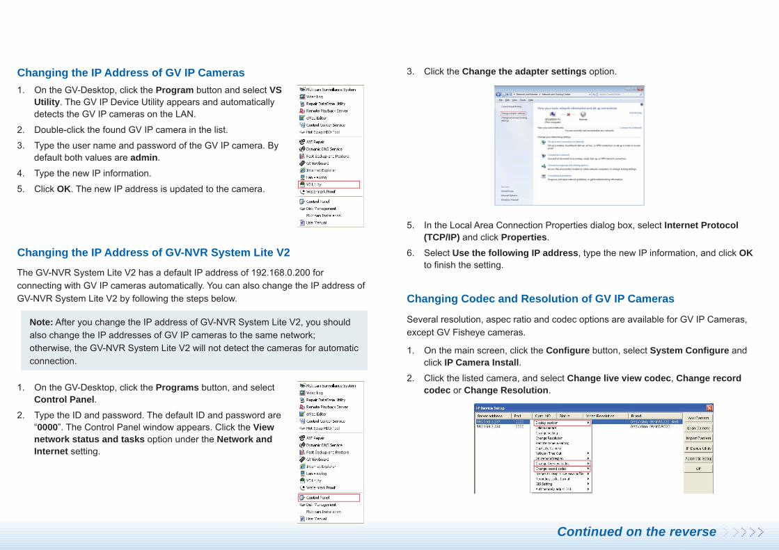
Note: After you change the IP address of GV-NVR System Lite V2, you should also change the IP addresses of GV IP cameras to the same network; otherwise, the GV-NVR System Lite V2 will not detect the cameras for automatic connection.
The GV-NVR System Lite V2 has a default IP address of 192.168.0.200 for connecting with GV IP cameras automatically. You can also change the IP address of GV-NVR System Lite V2 by following the steps below.
Changing the IP Address of GV IP Cameras
1. On the GV-Desktop, click the Programs button, and select Control Panel.
2. Type the ID and password. The default ID and password are “0000”. The Control Panel window appears. Click the View network status and tasks option under the Network and Internet setting.
3. Click the Change the adapter settings option.
5. In the Local Area Connection Properties dialog box, select Internet Protocol (TCP/IP) and click Properties.
6. Select Use the following IP address, type the new IP information, and click OK to finish the setting.
Changing the IP Address of GV-NVR System Lite V2
1. On the GV-Desktop, click the Program button and select VS Utility. The GV IP Device Utility appears and automatically detects the GV IP cameras on the LAN.
2. Double-click the found GV IP camera in the list.
3. Type the user name and password of the GV IP camera. By default both values are admin.
4. Type the new IP information.
5. Click OK. The new IP address is updated to the camera.
Several resolution, aspec ratio and codec options are available for GV IP Cameras, except GV Fisheye cameras.
1. On the main screen, click the Configure button, select System Configure and click IP Camera Install.
2. Click the listed camera, and select Change live view codec, Change record codec or Change Resolution.
Changing Codec and Resolution of GV IP Cameras
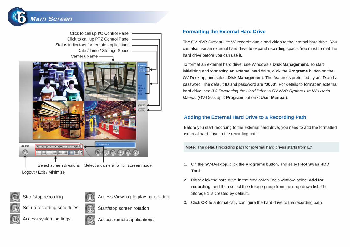
Start/stop recording
Set up recording schedules
Access system settings
Access ViewLog to play back video
Start/stop screen rotation
Access remote applications
Main ScreenM66
Logout / Exit / MinimizeSelect screen divisions Select a camera for full screen mode
Camera NameDate / Time / Storage Space
Status indicators for remote applicationsClick to call up PTZ Control Panel
Click to call up I/O Control Panel
Adding the External Hard Drive to a Recording Path
Before you start recording to the external hard drive, you need to add the formatted external hard drive to the recording path.
Note: The default recording path for external hard drives starts from E:\
1. On the GV-Desktop, click the Programs button, and select Hot Swap HDD Tool.
2. Right-click the hard drive in the MediaMan Tools window, select Add for recording, and then select the storage group from the drop-down list. The Storage 1 is created by default.
3. Click OK to automatically configure the hard drive to the recording path.
Formatting the External Hard Drive
The GV-NVR System Lite V2 records audio and video to the internal hard drive. You can also use an external hard drive to expand recording space. You must format the hard drive before you can use it.
To format an external hard drive, use Windows’s Disk Management. To start initializing and formatting an external hard drive, click the Programs button on the GV-Desktop, and select Disk Management. The feature is protected by an ID and a password. The default ID and password are “0000”. For details to format an external hard drive, see 3.5 Formatting the Hard Drive in GV-NVR System Lite V2 User’s Manual (GV-Desktop < Program button < User Manual).
Status field
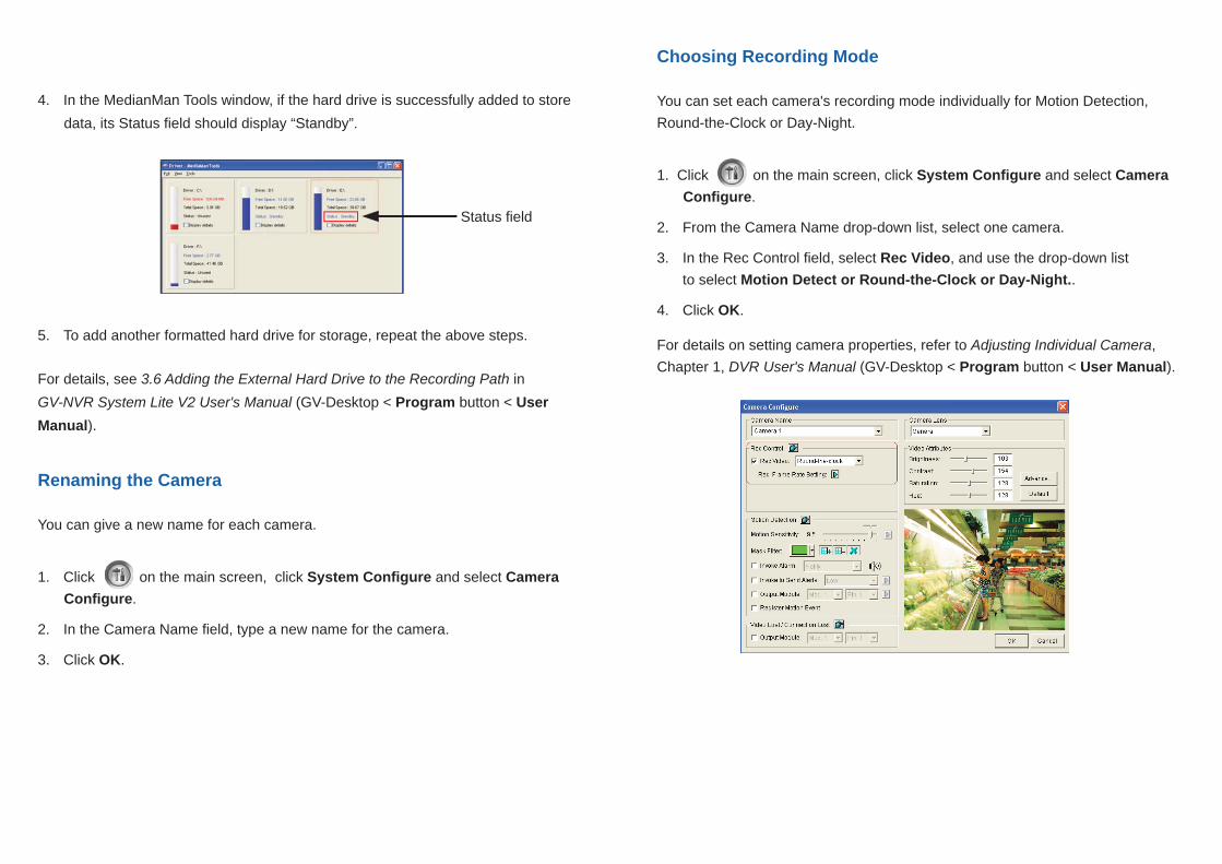
Choosing Recording Mode
You can set each camera's recording mode individually for Motion Detection, Round-the-Clock or Day-Night.
1. Click on the main screen, click System Configure and select Camera Configure.
2. From the Camera Name drop-down list, select one camera.
3. In the Rec Control field, select Rec Video, and use the drop-down list to select Motion Detect or Round-the-Clock or Day-Night..
4. Click OK.
For details on setting camera properties, refer to Adjusting Individual Camera, Chapter 1, DVR User's Manual (GV-Desktop < Program button < User Manual).
4. In the MedianMan Tools window, if the hard drive is successfully added to store data, its Status field should display “Standby”.
5. To add another formatted hard drive for storage, repeat the above steps.
Renaming the Camera
You can give a new name for each camera.
1. Click on the main screen, click System Configure and select Camera Configure.
2. In the Camera Name field, type a new name for the camera.
3. Click OK.
For details, see 3.6 Adding the External Hard Drive to the Recording Path in GV-NVR System Lite V2 User's Manual (GV-Desktop < Program button < User Manual).

You can program recording to turn on and off at a specific time each day.
1. Click on the main screen, and select Schedule Edit.
2. Select or enter the Start and End time of the schedule.
3. Select day(s).
4. Select Rec, and use the drop-down list to select Round-the-Clock or Motion Detect for recording mode.
5. Select camera(s).
6. Click Add Schedule.
7. Click OK.
For details, refer to Recording Schedule, Chapter 1, DVR User's Manual (GV-Desktop < Program button < User Manual).
Recording Schedule SetupR77
3
2
4
5
6
7
You can play back video recorded during a particular date and time.
1. Click on the main screen, and select Video/Audio Log.
2. Select the camera you wish to view.
3. Select a date folder from the date tree.
4. Select a time from the Video Events list.
5. Click to begin playback.
For details, refer to Playing Back Video Files, Chapter 4, DVR User's Manual (GV-Desktop < Program button < User Manual).
Video PlaybackV88
2
5
3
4
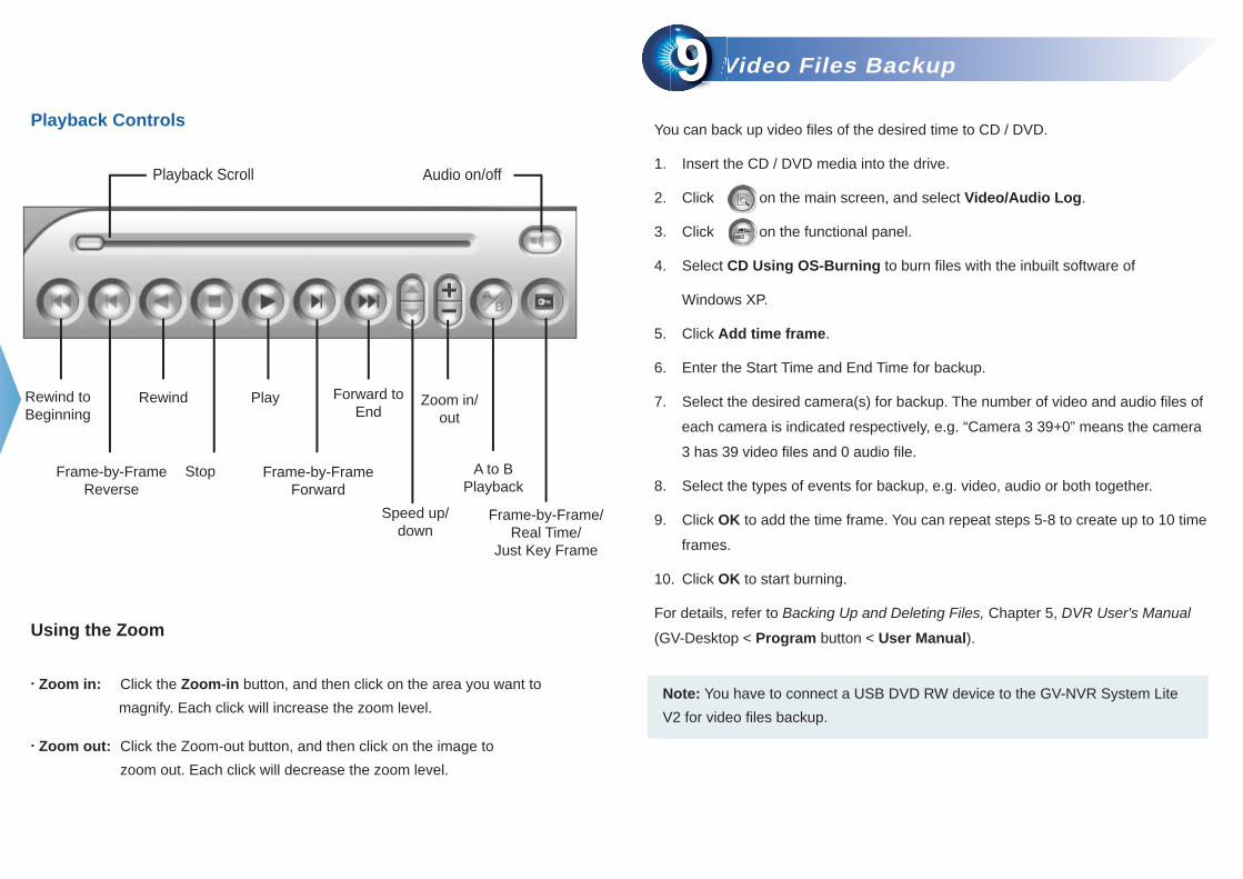
Playback Controls
Using the Zoom
. Zoom in: Click the Zoom-in button, and then click on the area you want to magnify. Each click will increase the zoom level.
. Zoom out: Click the Zoom-out button, and then click on the image to zoom out. Each click will decrease the zoom level.
Rewind Play
Stop
Rewind toBeginning
Frame-by-FrameReverse
Frame-by-FrameForward
Forward toEnd
Speed up/down
A to BPlayback
Zoom in/out
Frame-by-Frame/Real Time/
Just Key Frame
Playback Scroll Audio on/off
Video Files BackupV99You can back up video files of the desired time to CD / DVD.
1. Insert the CD / DVD media into the drive.
2. Click on the main screen, and select Video/Audio Log.
3. Click on the functional panel.
4. Select CD Using OS-Burning to burn files with the inbuilt software of
Windows XP.
5. Click Add time frame.
6. Enter the Start Time and End Time for backup.
7. Select the desired camera(s) for backup. The number of video and audio files of
each camera is indicated respectively, e.g. “Camera 3 39+0” means the camera
3 has 39 video files and 0 audio file.
8. Select the types of events for backup, e.g. video, audio or both together.
9. Click OK to add the time frame. You can repeat steps 5-8 to create up to 10 time
frames.
10. Click OK to start burning.
For details, refer to Backing Up and Deleting Files, Chapter 5, DVR User's Manual
(GV-Desktop < Program button < User Manual).
Note: You have to connect a USB DVD RW device to the GV-NVR System Lite V2 for video files backup.

Playing Backup Files
Open the backup folder, run EZViewLog500.exe, and then follow the instructions in the Video Playback section above.
6
9
7
8
4
5
10

Note: After recovery, you need to re-install all settings and passwords. But the recovery will not delete your recording files saved in the partition D since it only reformats the partition C.
9F, No. 246, Sec. 1, Neihu Rd., Neihu District, Taipei, TaiwanTel: +886-2-8797-8376 Fax: +886-2-8797-8335
[email protected] http://www.geovision.com.tw
System RestorationSS1010You can restore preinstalled files once they are damaged by running the recovery from the hidden partition. To restore the operating system and all preinstalled software, follow the steps below.
1. On the GV-Desktop, click the Program button and select Recovery.
4. When the below screen appears, press the Recovery button.
5. If you can’t successfully start the Recovery Wizard, you may see the below screen. Select SATA PM to start the Recovery Wizard.
6. When the restoring process is completed, the screen will automatically show the GV-Desktop. And the system will restore the default values.
2. Restart the GV-NVR System Lite V2.
3. Press F11 button several times to avoid accessing the system.


![東空販売株式会社型式 GV-15S GV-30S GV-40S GV-60S GV-120S GV-200S GV-300S GV-400S 本体クラス の目安[ton] 1.2~3 3~4 4~5 6~8 12~14 20~22 30~35 40~45](https://img.dokumen.tips/doc/110x75/5fbcb589660a9a3349511e44/cec-gv-15s-gv-30s-gv-40s-gv-60s-gv-120s-gv-200s-gv-300s.jpg)