Embed Size (px)
Citation preview

TAKE OUT WHAT YOU NEED
CABLE THE SWITCH
ASSIGN SWITCH INFORMATION
ACCESS THE SWITCH FROM YOUR BROWSER
1
2
3
4
Quick Start GuideCATALYST 3500 SERIES XL SWITCHES
SPEED
SYSTEMRPS
STATUS
MODE
UTILDUPLEX
1
2
12
34
56
78
910
1112
1314
1516
1718
1920
2122
2324
LINE PWR
SYSTEMRPS
STATUSDUPLX
SPEED
1
2
MODE
12
34
56
78
910
1112
1516
1314
1718
1920
2122
2324
SPEEDMODE
SYSTEMRPS
STATUSUTILDUPLEX
1
34
56
78
910
1112
13142
1516
1718
1920
2122
2324
2526
2728
2930
3132
3334
3536
3738
3940
4142
4344
4546
4748
1
2
2
12
10BaseT/100BaseT
hub
Cisco IPPhone
PC
GigabitEthernet
server
10BaseT/100BaseT
switch
10BaseT/100BaseTXworkstations
Web-based orSNMP-basedmanagement
station
Cisco IOScommand-line
interface
Serial cable
10BaseT/100BaseT
router
Crossovercabling
Straight-through cabling
GigaStackcabling
Single-modeor multimodefiber cabling
2
5
6
3
8
SPEED
SYSTEMRPS
STATUSUTIL
DUPLEX
7
4
1
MODE
Cisco IPPhone
1
2
2
1
1
2


1
Take Out What You Need
Note If any item is missing or damaged, contact your Cisco representative or reseller for
support.
Note You need to provide the Category 5 straight-through and crossover cables to connect
the switch ports to other Ethernet devices. In addition, the supplied RJ-45-to-DB-9 serial
adapter is for connecting the switch console port to a PC. You need to provide a
RJ-45-to-DB-25 female DTE adapter if you want to connect the switch console port to a
terminal. You can order a kit (part number ACS-DSBUASYN=) containing that adapter from
Cisco.
Catalyst 3500 series XL switch
Hardware installation guide and release notes
RJ-45-to-RJ-45 rollover console cable
AC power cable
RJ-45-to-DB-9 serial adapter
Rack-mount kit
Rubber feet
SYSTEM
RPS
STATUS
UTIL
DUPLX
SPEED
MODE
2
1
1 21X
2X
15X
16X
3 4 5 6 7 8 9 10 11 12 13 14 15 16 17 1817X
18X
31X
32X
19 20 21 22 23 24 25 26 27 28 29 30 31 32 33 3433X
34X
47X
48X
35 36 37 38 39 40 41 42 43 44 45 46 47 48
InstallationGuide
ReleaseNotes

2
Cable the Switch
1 2 3 4 5 6 7 8 9 10 11 121X
2X
11X
12X
SYSTEM
RPS
STATUSMODEMODE
UTIL
DUPLX
2
1
1 2 3 4 5 6 7 8 9 10 11 121X
2X
11X
12X
SYSTEM
RPS
STATUSMODEMODE
DUPLX
SPEED
LINE PWR
2
1
16 17 18 19 20 21 22 23 24
13X
14X
23X
24X
13 14 15
SYSTEM
RPS
STATUS
UTIL
DUPLX
SPEED
2
1
MODE
1X
2X
21 2219 2017 1815 1613 1411 129 107 85 63 41 2
23 24 25 26 27 28 29 30 31 32 33 34 35 36 37 38 39 40 41 42 43 44 45 46 47 48
1X
2X
15X
16X
17X
18X
31X
32X
33X
34X
47X
48X
4SYSTEM
RPS
STATUSMODEMODE
UTIL
DUPLX
8
12
3
56
7
1 2
1 2
1 2
1 2
GigaStackcable
1000BaseXGBIC
Category 5straight-throughcable
RJ-45Ethernet port
RJ-4510/100 port GigaStack
GBIC
Connect to Workstations,PCs, Servers, and Routers1 Connect a Category 5 straight-through
cable (not supplied) to a 10/100 port on
the front panel of the switch.
2 Connect the other end of the cable to
the RJ-45 port of the workstation, PC,
server, or router.
Connect to Hubs and OtherSwitches1 Connect a Category 5 crossover cable
(not supplied) to a 10/100 port on the
front panel of the switch.
2 Connect the other end of the cable to an
RJ-45 port on the target switch or hub.
Note Use a straight-through cable to
connect two ports when one of the port
numbers is designated with an X. Use a
crossover cable to connect two ports when
both port numbers are designated with an X
or when both ports do not have an X.
Connect through theGigaStack GBICs (Optional)1 Insert GigaStack Gigabit Interface
Convertors (GBICs) in the GBIC
module slots on the switches.
2 Connect the GigaStack GBICs with the
Cisco GigaStack cables.
Note The GigaStack GBICs are orderable
separately. Refer to the Catalyst GigaStack
Gigabit Interface Convertor Installation
Guide for details on installing and cabling
the GigaStack GBICs.
3
1 2 3 4 5 6 7 8 9 10 11 121X
2X
11X
12X
SYSTEM
RPS
STATUSMODEMODE
UTIL
DUPLX
2
1
16 17 18 19 20 21 22 23 24
13X
14X
23X
24X
13 14 15
1 2 3 4 5 6 7 8 9 10 11 121X
2X
11X
12X
SYSTEM
RPS
STATUSMODEMODE
DUPLX
SPEED
LINE PWR
2
1
16 17 18 19 20 21 22 23 24
13X
14X
23X
24X
13 14 15
Cisco IP Phone
Cisco IP Phone
PC
PC
Catalyst 3524-PWR XL switch
Connect to Cisco IP PhonesThe Catalyst 3524-PWR XL 10/100 ports
also can provide inline power to Cisco IP
Phones.
1 Connect a Category 5 straight-through
cable (not supplied) to a 10/100 port on
the front panel of the switch.
2 Connect the other end of the cable to
the LAN-to-phone jack on the Cisco IP
Phone.
Note The rear panel of the Cisco IP Phone
might have more than one RJ-45 jack. Use
the LAN-to-phone jack to connect the
phone to the Catalyst 3524-PWR XL
switch. Refer to the documentation that
came with your Cisco IP Phone for
information about connecting devices to it.

4
RJ-45console port
Catalyst 3524 XL switch
RJ-45-to-RJ-45rollover cable
RJ-45-to-DB-9 adapter(labeled TERMINAL)
DC INPUTS FOR REMOTEPOWER SUPPLY
SPECIFIED IN MANUAL.+5V @24A, +12V @.5A
RATING100-127/200-240V1.0A/0.5A 50-60HZ CONSOLE
Connect to a Power Source1 Connect one end of the supplied AC
power cord to the power connector on
the switch rear panel.
2 Connect the other end of the power
cable to a grounded AC outlet.
Note If you are connecting the switch to a
Cisco Redundant Power System (RPS), refer
to the documentation that shipped with your
RPS.Specific Cisco RPS models support
specific Catalyst 3500 XL switches:
• Cisco RPS 600
(model PWR600-AC-RPS) supports the
Catalyst 3512, 3524, 3548, and
3508 XL switches.
• Cisco RPS 300
(model PWR300-AC-RPS) supports the
Catalyst 3524-PWR XL switch.
Connect to a PC or Terminal1 Connect the blue rollover cable to the
port marked CONSOLE on the rear
panel of the switch.
2 If necessary, attach the RJ-45-to-DB-9
adapter to the PC, or attach the
appropriate adapter to a terminal. You
can order a kit (part number
ACS-DSBUASYN=) containing the
terminal adapter from Cisco.
3 Connect the other end of the cable to
the PC or terminal running
terminal-emulation software, such as
ProComm Plus or HyperTerminal.
4 If necessary, reconfigure the
terminal-emulation software to match
the console port settings
(default settings are 9600 baud,
no parity, 8 data bits, and 1 stop bit).

5
Assign Switch Information
The first time that you access the switch, it
runs a setup program that prompts you for
IP and other configuration information
necessary for the switch to communicate
with the local routers and the Internet. This
information also is required if you plan to
use the Cluster Management Suite of
applications to configure and manage the
switch.
Note If the switch will be a cluster member
managed through the IP address of the
command switch, it is not necessary to assign
IP information or a password. If you are
configuring the switch as a standalone switch
or as a command switch, you must assign IP
information. Refer to theCisco IOS Desktop
Switching Software Configuration Guide for
more information.
IP Information RequirementsYou will need the following information
from your system administrator:
• Switch IP address
• Subnet mask (IP netmask)
• Default gateway (router)
• Enable secret password
First-Time SetupUse this procedure to create an initial
configuration for the switch:
1 Enter Y at the prompt:
Continue with configuration dialog?[yes/no]: y
If this prompt does not appear, enter
enable, and press Return. Enter setup,
and press Return to restart the setup
program.
2 Enter the switch IP address, and press
Return:
Enter IP address: ip_address
3 Enter the subnet mask (IP netmask)
address, and press Return:
Enter IP netmask: ip_netmask
4 Enter Y to enter a default gateway
(router):
Would you like to enter a defaultgateway address? [yes]: y
5 Enter the IP address of the default
gateway, and press Return:
IP address of the default gateway:ip_address

6
6 Enter the host name for the switch, and
press Return.
Note On a command switch, the host
name is limited to 28 characters and on a
member switch to 31 characters. Do not use
-n, where n is a number, as the last
characters in a host name for any switch.
Enter the host name: host_name
7 Enter a secret password (which ensures
switch security), and press Return:
Note The secret password can be from 1 to
25 alphanumeric characters, can start with a
number, is case-sensitive, and allows spaces
but ignores leading spaces.
Enter enable secret:secret_password
8 Enter Y to enter a Telnet password:
Would you like to configure aTelnet password? [yes]: y
9 Enter the Telnet password, and press
Return:
Note The Telnet password can be from
1 to 25 alphanumeric characters, is
case-sensitive, allows spaces, but ignores
leading spaces.
Enter Telnet password:telnet_password
10 Enter Y to configure this switch as the
cluster command switch. Enter N to
configure it as a member switch or as a
standalone switch.
Note If you enter N to configure the switch
as a member switch or as a standalone
switch, it appears as a candidate switch in
Cluster Builder, and the Step 11 message is
not displayed.
Would you like to enable as acluster command switch? y
11 Assign a name to the cluster, and press
Return:
Note The cluster name can be 1 to
31 alphanumeric characters, dashes, or
underscores.
Enter cluster name: cls_name

7
12 Verify that the addresses are correct in
the initial configuration displayed:
The following configuration commandscript was created:
ip subnet-zerointerface VLAN1ip address ip_address ip_netmaskip default-gateway ip_addresshostname host_nameenable secret 5$1$M3pS$cXtAlkyR3/6Cn8/line vty 0 15password telnet_passwordsnmp community private rwsnmp community public rocluster enable cls_name!end!Use this configuration? [yes/no]:
13 If the information is correct, enterY at
the prompt, and pressReturn to use the
displayed configuration. When you see
the message “Press RETURN to get
started,” the setup program is complete.
You can use your browser and the Cluster
Management Suite or use the
command-line interface (CLI) to manage
the switch.
If the information is not correct, enter N
at the prompt, press Return, and begin
again at Step 1.
Where to Go NextAfter you complete the setup program, the
switch can run the created default
configuration. If you want to change this
configuration or want to perform other
management tasks, use one of these tools:
• CLI
• Cluster Management Suite from your
browser
To use the CLI, enter commands at the
switch> prompt. Refer to the Cisco IOS
Desktop Switching Software Configuration
Guide or the Cisco IOS Desktop Switching
Command Reference (online only) for
configuration information.
To use the Cluster Management Suite, go to
the “Access the Switch from Your Browser”
section on page 8.

8
Access the Switch from Your BrowserDownloading the Required Plug-InA Java browser plug-in is required to access the HTML interface. You can download the plug-in
from Cisco Connection Online (CCO). If you have a SmartNet support contract, you can log
in to the following URL and download the plug-in:
• http://www.cisco.com/cgi-bin/tablebuild.pl/cat3500XL
If you do not have a SmartNet contract, you can download the plug-in from the following URL:
• http://www.cisco.com/pcgi-bin/tablebuild.pl/cat3500XL
Follow the instructions that accompany the plug-in to install it on your computer.
Supported Operating Platforms and Network BrowsersAfter you have assigned an IP address to the switch and installed the plug-in, you can access the
switch from your browser and use the Cluster Management Suite to view or change
configuration settings. If this is a command switch, you also can use the Cluster Management
application to configure other switches. To use web-based tools, follow the procedure to set the
appropriate browser options.
The web-based tools support the following platforms and network browsers:
Note Netscape Communicator version 4.60 is NOT supported.
The switch checks the browser version when starting a session to ensure that the browser is
supported. If the browser is not supported, the switch displays a warning message.
Note Refer to the release notes for additional requirements for setting up your browser.
Operating SystemMinimum Operating SystemRequirements Netscape Communicator
MicrosoftInternet Explorer
Windows 95 Service Pack 1 4.61 or 4.7 4.01a or 5.0
Windows 98 Second Edition 4.61 or 4.7 4.01a or 5.0
Windows NT Service Pack 3 4.61 or 4.7 4.01a or 5.0
Solaris 2.5.1 or higher SUN-recommended patchcluster for the OS and Motiflibrary patch 103461-24
4.61 or 4.7 Not supported

9
Configuring NetscapeCommunicator (All Versions)1 From the menu bar, select
Edit>Preferences.
2 In the Preferences window, click
Advanced.
3 Select the Enable Java, the Enable
JavaScript, and the Enable Style Sheets
check boxes.
4 From the Advanced drop-down list,
select Cache.
5 Under Document in cache is compared
to document on network, select Every
time.
6 Click OK.
Configuring Internet Explorer(4.01a)Note For the procedure to configure
Internet Explorer 5.0, refer to the Cisco IOS
Desktop Switching Software Configuration
Guide.
1 From the menu bar, select
View>Internet Options.
2 In the Internet Options window, click
Advanced.
3 Scroll through the list of options to Java
VM, select the Java JIT compiler
enabled and the Java logging enabled
check boxes, and click Apply.
4 Click General. In the Temporary
Internet Files section, click Settings. The
Settings window opens.
5 Select Every visit to the page, and click
OK.
6 In the Internet Options window, click
Security.
7 In the Zone drop-down list, select
Trusted Sites Zone, and click Custom.
8 Click Settings.
9 In the Java>Java permissions section,
select Custom. Click the Java Custom
Setting, which appears at the bottom of
the window.
10 In the Trusted Sites Zone window, click
Edit Permissions.
11 If the buttons under Run Unsigned
Content are not available, select either
Medium or Low security in the Reset
Java Permissions list box, and click
Reset.
12 Under Run Unsigned Content, select
Enable, and click OK.
13 In the Security Settings window, click
OK.
14 In the Internet Options window, click
Security. Verify that the Zone
drop-down list is set to Trusted Sites
Zone.
15 In the Trusted Sites Zone section, click
Add Sites.
10
16 In the Trusted Sites Zone window,
deselect the Require server verification
check box.
17 In the Add this Web site to the Zone
field, enter the IP address of the switch.
Note If the you plan to use Cluster
Management for switch configuration, you
must enter the address of the cluster
command switch. You also can enter the
addresses of the member switches, but they
are not required. If you plan to use Visual
Switch Manager (VSM) for switch
configuration, you must enter the IP address
of each switch that you want to manage.
You do not need to delete the address from
the Trusted Sites list if the switch later
becomes a cluster member. Refer to the
Cisco IOS Desktop Switching Software
Configuration Guide for more information.
18 Click Add, and then click OK.
19 In the Internet Options window, click
Apply, and then click OK.
Displaying the Access PageAfter the browser is configured, display the
Cluster Management Suite access page:
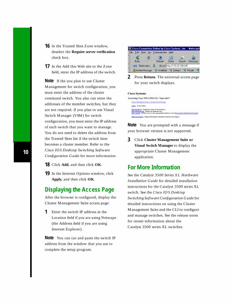
1 Enter the switch IP address in the
Location field if you are using Netscape
(the Address field if you are using
Internet Explorer).
Note You can cut and paste the switch IP
address from the window that you use to
complete the setup program.
2 Press Return. The universal access page
for your switch displays.
Note You are prompted with a message if
your browser version is not supported.
3 Click Cluster Management Suite or
Visual Switch Manager to display the
appropriate Cluster Management
application.
For More InformationSee the Catalyst 3500 Series XL Hardware
Installation Guide for detailed installation
instructions for the Catalyst 3500 series XL
switch. See the Cisco IOS Desktop
Switching Software Configuration Guide for
detailed instructions on using the Cluster
Management Suite and the CLI to configure
and manage switches. See the release notes
for recent information about the
Catalyst 3500 series XL switches.
Cluster Management Suite or Visual Switch Manager


Corporate HeadquartersCisco Systems, Inc.170 West Tasman DriveSan Jose, CA 95134-1706USAhttp://www.cisco.comTel: 408 526-4000
800 553-NETS (6387)Fax: 408 526-4100
European HeadquartersCisco Systems Europe11, Rue Camille Desmoulins92782 Issy Les MoulineauxCedex 9Francehttp://www-europe.cisco.comTel: 33 1 58 04 60 00Fax: 33 1 58 04 61 00
AmericasHeadquartersCisco Systems, Inc.170 West Tasman DriveSan Jose, CA 95134-1706USAhttp://www.cisco.comTel: 408 526-7660Fax: 408 527-0883
Asia HeadquartersNihon Cisco Systems K.K.Fuji Building, 9th Floor3-2-3 MarunouchiChiyoda-ku, Tokyo 100Japanhttp://www.cisco.comTel: 81 3 5219 6250Fax: 81 3 5219 6001
Printed in the USA on recycled paper containing 10% postconsumer waste.
Cisco Systems has more than 200 offices in the following countries. Addresses, phone numbers, and fax numbers are listed on theC i s c o C o n n e c t i o n O n l i n e W e b s i t e a t h t t p : / / w w w . c i s c o . c o m / g o / o f f i c e s .
Argentina • Australia • Austria • Belgium • Brazil • Canada • Chile • China • Colombia • Costa Rica • Croatia • Czech Republic • Denmark • Dubai, UAE
Finland • France • Germany • Greece • Hong Kong • Hungary • India • Indonesia • Ireland • Israel • Italy • Japan • Korea • Luxembourg • Malaysia
Mexico • The Netherlands • New Zealand • Norway • Peru • Philippines • Poland • Portugal • Puerto Rico • Romania • Russia • Saudi Arabia • Singapore
Slovakia • Slovenia • South Africa • Spain • Sweden • Switzerland • Taiwan • Thailand • Turkey • Ukraine • United Kingdom • United States •
VenezuelaAccess Registrar, AccessPath, Any to Any, AtmDirector, Browse with Me, CCDA, CCDE, CCDP, CCIE, CCNA, CCNP, CCSI, CD-PAC, the Cisco logo, Cisco Certified InternetworkExpert logo, CiscoLink, the Cisco Management Connection logo, the Cisco NetWorks logo, the Cisco Powered Network logo, Cisco Systems Capital, the Cisco Systems Capital logo,Cisco Systems Networking Academy, the Cisco Systems Networking Academy logo, the Cisco Technologies logo, ConnectWay, Fast Step, FireRunner, Follow Me Browsing,FormShare, GigaStack, IGX, Intelligence in the Optical Core, Internet Quotient, IP/VC, Kernel Proxy, MGX, Natural Network Viewer, NetSonar, Network Registrar, the Networkerslogo, Packet, PIX, Point and Click Internetworking, Policy Builder, Precept, RateMUX, ScriptShare, Secure Script, ServiceWay, Shop with Me, SlideCast, SMARTnet, SVX, The Cell,TrafficDirector, TransPath, ViewRunner, Virtual Loop Carrier System, Virtual Voice Line, VlanDirector, Voice LAN, Wavelength Router, Workgroup Director, and Workgroup Stackare trademarks; Changing the Way We Work, Live, Play, and Learn, Empowering the Internet Generation, The Internet Economy, and The New Internet Economy are service marks;and Aironet, ASIST, BPX, Catalyst, Cisco, Cisco IOS, the Cisco IOS logo, Cisco Systems, the Cisco Systems logo, the Cisco Systems Cisco Press logo, Enterprise/Solver, EtherChannel,EtherSwitch, FastHub, FastLink, FastPAD, FastSwitch, GeoTel, IOS, IP/TV, IPX, LightStream, LightSwitch, MICA, NetRanger, Post-Routing, Pre-Routing, Registrar, StrataView Plus,Stratm, TeleRouter, and VCO are registered trademarks of Cisco Systems, Inc. or its affiliates in the U.S. and certain other countries. All other trademarks mentioned in this documentare the property of their respective owners. The use of the word partner does not imply a partnership relationship between Cisco and any of its resellers. (0004R)
78-6458-03