Embed Size (px)
Citation preview

-1
QUICK REFERENCE INDEX A GENERAL INFORMATION GI General Information
B ENGINE EM Engine Mechanical
LU Engine Lubrication System
CO Engine Cooling System
EC Engine Control System
FL Fuel System
EX Exhaust System
ACC Accelerator Control System
C TRANSMISSION/TRANSAXLE
CL Clutch
MT Manual Transmission
AT Automatic Transmission
D DRIVELINE/AXLE TF Transfer
PR Propeller Shaft
FFD Front Final Drive
RFD Rear Final Drive
FAX Front Axle
RAX Rear Axle
E SUSPENSION FSU Front Suspension
RSU Rear Suspension
WT Road Wheels & Tires
F BRAKES BR Brake System
PB Parking Brake System
BRC Brake Control System
G STEERING PS Power Steering System
H RESTRAINTS SB Seat Belts
SRS Supplemental Restraint System (SRS)
I BODY BL Body, Lock & Security System
GW Glasses, Window System & Mirrors
RF Roof
EI Exterior & Interior
IP Instrument Panel
SE Seat
J AIR CONDITIONER MTC Manual Air Conditioner
K ELECTRICAL SC Starting & Charging System
LT Lighting System
DI Driver Information System
WW Wiper, Washer & Horn
BCS Body Control System
AV Audio Visual & Telephone System
ACS Auto Cruise Control System
PG Power Supply, Ground & Circuit Elements
L MAINTENANCE MA Maintenance
M INDEX IDX Alphabetical Index
Edition: September 2002Revision: February 2004Publication No. SM3E-1D22U2
B
D
© 2004 NISSAN NORTH AMERICA, INC.All rights reserved. No part of this Service Manual may be reproduced or stored in a retrieval system, or transmitted in any form, or by any means, electronic, mechanical, photo-copying, recording or otherwise, without the prior written permission of Nissan North America, Inc., Gardena, California.
A
C
EFGHIJKLM
-2
This manual contains maintenance and repair procedures for the2003 NISSAN FRONTIER.
In order to assure your safety and the efficient functioning of the vehicle, this manual should be read thoroughly. It is especially important that the PRECAUTIONS in the GI section be completely understood before starting any repair task.
All information in this manual is based on the latest product informationat the time of publication. The right is reserved to make changes in specifi-cations and methods at any time without notice.
IMPORTANT SAFETY NOTICE
The proper performance of service is essential for both the safety ofthe technician and the efficient functioning of the vehicle.The service methods in this Service Manual are described in such amanner that the service may be performed safely and accurately.Service varies with the procedures used, the skills of the technicianand the tools and parts available. Accordingly, anyone using serviceprocedures, tools or parts which are not specifically recommendedby NISSAN must first be completely satisfied that neither personalsafety nor the vehicle’s safety will be jeopardized by the servicemethod selected.

PLEASE HELP MAKE THIS SERVICE MANUAL BETTER!
Your comments are important to NISSAN and will help us to improve our Service Manuals.
Use this form to report any issues or comments you may have regarding our Service Manuals.
Please print this form and type or write your comments below. Mail or fax to:
Nissan North America, Inc.Technical Service Information39001 Sunrise Drive, P.O. Box 9200Farmington Hills, MI USA 48331FAX: (248) 488-3910
SERVICE MANUAL: Model: Year:
PUBLICATION NO. (Refer to Quick Reference Index ):
Please describe any Service Manual issues or problems in detail:
Page number(s) Note: Please include a copy of each page, marked with your comments.
Are the trouble diagnosis procedures logical and easy to use? (circle your answer) YES NO
If no, what page number(s)? Note: Please include a copy of each page, marked with your comments.
Please describe the issue or problem in detail:
Is the organization of the manual clear and easy to follow? (circle your answer) YES NO
Please comment:
What information should be included in NISSAN Service Manuals to better support you in servicing orrepairing customer vehicles?
DATE: YOUR NAME: POSITION:
DEALER: DEALER NO.: ADDRESS:
CITY: STATE/PROV./COUNTRY: ZIP/POSTAL CODE:

QUICK REFERENCE CHART: FRONTIER EQUIPPED WITH KA24DE ENGINE 2003
QUICK REFERENCE CHART: FRONTIER EQUIPPED WITH KA24DE ENGINEPFP:00027
Engine Tune-Up Data ELS000OU
Idle Speed and Ignition Timing
*1: Throttle position sensor harness connector disconnected or using CONSULT-II “WORK SUPPORT” mode*2: Throttle position sensor harness connector connected*3: Under the following conditions:
● Air conditioner switch: OFF
● Electrical load: OFF (Lights, heater fan & rear window defogger)
● Steering wheel: Kept in straight-ahead position
Drive Belt Deflection and Tension
*1: If belt tension gauge cannot be installed at check point shown, check belt tension at a different location on the belt.
Engine KA24DE
Classification Gasoline
Cylinder arrangement In-line 4
Displacement 2,389 cm3 (145.78 cu in)
Bore and stroke 89 x 96 mm (3.50 x 3.78 in)
Valve arrangement DOHC
Firing order 1-3-4-2
Number of piston ringsCompression 2
Oil 1
Number of main bearings 5
Compression ratio 9.2
Cap relief pressure Standard kPa (kg/cm2, psi) 78 - 98 (0.8 - 1.0, 11 - 14)
Limit kPa (kg/cm2, psi) 59 (0.6, 9)
Leakage test pressure kPa (kg/cm2, psi) 157 (1.6, 23)
Oil drain plug tightening specification29.4 - 39.2 N·m (3.0 - 4.0 kg-m, 21.69 -
28.91 lb-ft)
Base idle speed*1 rpm No-load*3 (in “P” or “N” position) 750±50
Target idle speed*2 rpm No-load*3 (in “P” or “N” position) 800±50
Air conditioner: ON rpm In “P” or “N” position 875 or more
Ignition timing*1 In “P” or “N” position 20°±2° BTDC
Deflection adjustment Unit: mm (in) Tension adjustment *1 Unit: N (kg, lb)
Used beltNew belt
Used beltNew belt
Limit After adjustment Limit After adjustment
Generator 17 (0.67)10 - 12 (0.39 -
0.47)8 - 10 (0.31 -
0.39)222.4 (22.7,
50)
355.8 - 444.8 (36.3 - 45.4, 80 -
100)
489.3 - 578.2 (49.9 - 59.0, 110 - 130)
Air conditioner com-pressor
16 (0.63)10 - 12 (0.39 -
0.47)8 - 10 (0.31 -
0.39)200.2 (20.4,
45)
355.8 - 444.8 (36.3 - 45.4, 80 -
100)
489.3 - 578.2 (49.9 - 59.0, 110 - 130)
Power steering oil pump
17 (0.67)10 - 13 (0.39 -
0.51)8 - 10 (0.31 -
0.39)222.4 (22.7,
50)
355.8 - 444.8 (36.3 - 45.4, 80 -
100)
489.3 - 578.2 (49.9 - 59.0, 110 - 130)
Applied pushing force
98 N (10 kg, 22 lb) —
2003QUICK REFERENCE CHART: FRONTIER EQUIPPED WITH KA24DE
ENGINE
Spark Plugs (Double Platinum Tipped)
Wheel Bearing (Front) ELS000QB
Clutch Pedal ELS000QC
Unit: mm (in)
*: Measured from surface of dash lower panel to pedal pad.
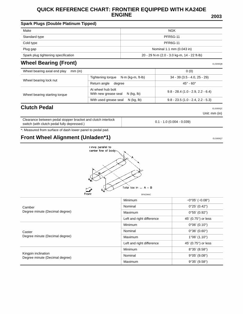
Front Wheel Alignment (Unladen*1) ELS000Q7
Make NGK
Standard type PFR5G-11
Cold type PFR6G-11
Plug gap Nominal 1.1 mm (0.043 in)
Spark plug tightening specification 20 - 29 N·m (2.0 - 3.0 kg-m, 14 - 22 ft-lb)
Wheel bearing axial end play mm (in) 0 (0)
Wheel bearing lock nutTightening torque N·m (kg-m, ft-lb) 34 - 39 (3.5 - 4.0, 25 - 29)
Return angle degree 45° - 60°
Wheel bearing starting torque
At wheel hub boltWith new grease seal N (kg, lb)
9.8 - 28.4 (1.0 - 2.9, 2.2 - 6.4)
With used grease seal N (kg, lb) 9.8 - 23.5 (1.0 - 2.4, 2.2 - 5.3)
Clearance between pedal stopper bracket and clutch interlock switch (with clutch pedal fully depressed.)
0.1 - 1.0 (0.004 - 0.039)
CamberDegree minute (Decimal degree)
Minimum −0°05′ (−0.08°)
Nominal 0°25′ (0.42°)
Maximum 0°55′ (0.92°)
Left and right difference 45′ (0.75°) or less
CasterDegree minute (Decimal degree)
Minimum 0°06′ (0.10°)
Nominal 0°36′ (0.60°)
Maximum 1°06′ (1.10°)
Left and right difference 45′ (0.75°) or less
Kingpin inclinationDegree minute (Decimal degree)
Minimum 8°35′ (8.58°)
Nominal 9°05′ (9.08°)
Maximum 9°35′ (9.58°)
SFA234AC
QUICK REFERENCE CHART: FRONTIER EQUIPPED WITH KA24DE ENGINE 2003
*1: Fuel, radiator coolant and engine oil full. Spare tire, jack, hand tools and mats in designated positions.*2: Wheel turning force (at circumference of steering wheel) of 98 to 147 N (10 to 15 kg, 22 to 33 lb) with engine idle.
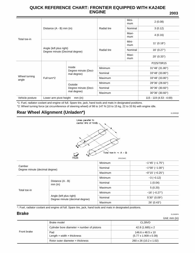
Rear Wheel Alignment (Unladen*) ELS000Q8
*: Fuel, radiator coolant and engine oil full. Spare tire, jack, hand tools and mats in designated positions.
Brake ELS000P4
Unit: mm (in)
Total toe-in
Distance (A - B) mm (in) Radial tire
Mini-mum
2 (0.08)
Nominal 3 (0.12)
Maxi-mum
4 (0.16)
Angle (left plus right)Degree minute (Decimal degree)
Radial tire
Mini-mum
11′ (0.18°)
Nominal 16′ (0.27°)
Maxi-mum
20′ (0.33°)
Wheel turning angle
Full turn*2
InsideDegree minute (Deci-mal degree)
P225/70R15
Minimum 31°48′ (31.80°)
Nominal 33°48′ (33.80°)
Maximum 33°48′ (33.80°)
OutsideDegree minute (Deci-mal degree)
Minimum 28°36′ (28.60°)
Nominal 30°36′ (30.60°)
Maximum 30°36′ (30.60°)
Vehicle posture Lower arm pivot height mm (in) 115 - 119 (4.53 - 4.69)
CamberDegree minute (decimal degree)
Minimum −1°45′ (−1.75°)
Nominal −1°00′ (−1.00°)
Maximum −0°15′ (−0.25°)
Total toe-in
Distance (A - B)mm (in)
Minimum −3 (−0.12)
Nominal 1 (0.04)
Maximum 5 (0.20)
Angle (left plus right)Degree minute (decimal degree)
Minimum −16′ (−0.27°)
Nominal 5′30″ (0.09°)
Maximum 26′ (0.43°)
SFA234AC
Front brake
Brake model CL28VD
Cylinder bore diameter × number of pistons 42.8 (1.685) x 2
Pad Length × width × thickness
146.6 x 48.5 x 10 (5.77 x 1.909 x 0.39)
Rotor outer diameter × thickness 260 x 26 (10.2 x 1.02)
2003QUICK REFERENCE CHART: FRONTIER EQUIPPED WITH KA24DE
ENGINE
Disc Brake - Repair LimitsUnit: mm (in)
Drum Brake - Repair LimitsUnit: mm (in)
Refill Capacities ELS000PA
Rear brake
Brake model LT26B
Cylinder bore diameter 22.22 (7/8)
Lining length × width × thickness 249.6 x 40 x 5.5 (9.83 x 1.57 x 0.217
Drum inner diameter 260.0 (10.23)
Master cylinder Bore diameter 25.40 (1)
Brake booster
Booster model M195T
Diaphragm diameterPri: 205 (8.07)Sec: 180 (7.09)
Recommended brake fluidGenuine NISSAN Super Heavy Duty Brake Fluid or
equivilent DOT 3 (US FMVSS No. 116)
Brake model CL28VD
Pad Wear limit minimum thickness 2.0 (0.079)
Standard pad thickness 10 (0.39)
Rotor repair limit Minimum thickness 24.0 (0.945)
Rotor runout Maximum 0.07 (0.0028)
Rotor thickness variation Maximum 0.02 (0.0008)
Brake model LT26B
Lining wear limitMinimum thickness 1.5 (0.059)
Standard thickness 5.5 (0.217)
Drum repair limitMaximum inner diameter 261.5 (10.30)
Out-of-round limit 0.03 (0.0012)
Description
Capacity (Approximate)
US measureImp mea-
sureLiter
Engine oilDrain and Refill
With oil filter 3 3/4 qt 3 1/8 qt 3.5
Without oil filter 3 1/2 qt 2 7/8 qt 3.3
Dry engine (Engine overhaul) 4 1/2 qt 3 3/4 qt 4.1
Cooling system (without reservoir)M/T 6 7/8 qt 5 3/4 qt 6.5
A/T 6 5/8 qt 5 1/2 qt 6.3
Cooling system reservoir 7/8 qt 3/4 qt 0.8
Manual transmission gear oil (FS5W71C) 2 1/8 qt 1 3/4 qt 2.0
Differential carrier gear oil C200 1 3/8 qt 1 1/8 qt 1.3
Automatic transmission fluid 8 3/8 qt 7 qt 7.9
Power steering fluid30.4-33.8 fl
oz31.7-35.2 fl
oz0.9-1.0
Air conditioning system refrigerant HFC 134a (R-134a) 1.32 - 1.54 lb1.32 - 1.54
lb60 - 70 kg
Air conditioning system compressor oil Genuine NISSAN A/C System Lubricant Type R or equivalent
6.8 fl oz 7.0 fl oz 200 m
QUICK REFERENCE CHART: FRONTIER EQUIPPED WITH VG33E/VG33ER ENGINES 2003
QUICK REFERENCE CHART: FRONTIER EQUIPPED WITH VG33E/VG33ERENGINES PFP:00027
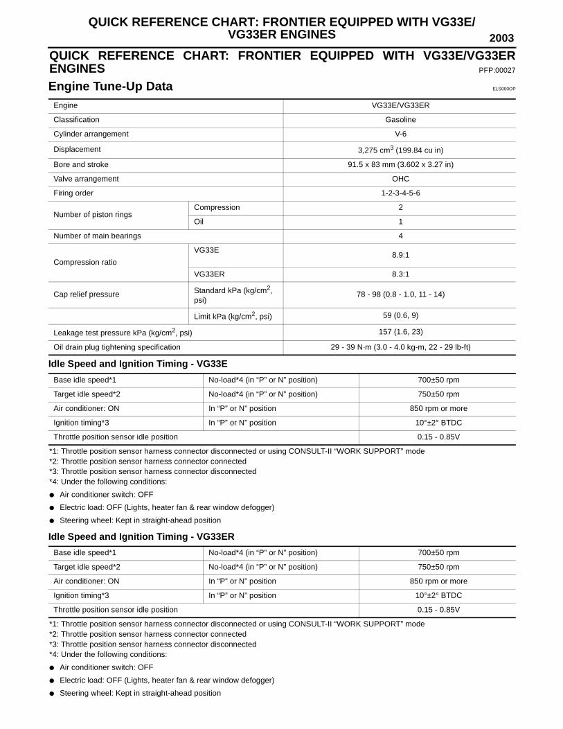
Engine Tune-Up Data ELS000OP
Idle Speed and Ignition Timing - VG33E
*1: Throttle position sensor harness connector disconnected or using CONSULT-II “WORK SUPPORT” mode*2: Throttle position sensor harness connector connected*3: Throttle position sensor harness connector disconnected*4: Under the following conditions:
● Air conditioner switch: OFF
● Electric load: OFF (Lights, heater fan & rear window defogger)
● Steering wheel: Kept in straight-ahead position
Idle Speed and Ignition Timing - VG33ER
*1: Throttle position sensor harness connector disconnected or using CONSULT-II “WORK SUPPORT” mode*2: Throttle position sensor harness connector connected*3: Throttle position sensor harness connector disconnected*4: Under the following conditions:
● Air conditioner switch: OFF
● Electric load: OFF (Lights, heater fan & rear window defogger)
● Steering wheel: Kept in straight-ahead position
Engine VG33E/VG33ER
Classification Gasoline
Cylinder arrangement V-6
Displacement 3,275 cm3 (199.84 cu in)
Bore and stroke 91.5 x 83 mm (3.602 x 3.27 in)
Valve arrangement OHC
Firing order 1-2-3-4-5-6
Number of piston ringsCompression 2
Oil 1
Number of main bearings 4
Compression ratio
VG33E8.9:1
VG33ER 8.3:1
Cap relief pressure Standard kPa (kg/cm2, psi)
78 - 98 (0.8 - 1.0, 11 - 14)
Limit kPa (kg/cm2, psi) 59 (0.6, 9)
Leakage test pressure kPa (kg/cm2, psi) 157 (1.6, 23)
Oil drain plug tightening specification 29 - 39 N·m (3.0 - 4.0 kg-m, 22 - 29 lb-ft)
Base idle speed*1 No-load*4 (in “P” or N” position) 700±50 rpm
Target idle speed*2 No-load*4 (in “P” or N” position) 750±50 rpm
Air conditioner: ON In “P” or N” position 850 rpm or more
Ignition timing*3 In “P” or N” position 10°±2° BTDC
Throttle position sensor idle position 0.15 - 0.85V
Base idle speed*1 No-load*4 (in “P” or N” position) 700±50 rpm
Target idle speed*2 No-load*4 (in “P” or N” position) 750±50 rpm
Air conditioner: ON In “P” or N” position 850 rpm or more
Ignition timing*3 In “P” or N” position 10°±2° BTDC
Throttle position sensor idle position 0.15 - 0.85V

2003QUICK REFERENCE CHART: FRONTIER EQUIPPED WITH VG33E/
VG33ER ENGINES
Drive Belt Deflection and Tension
*1: If belt tension gauge cannot be installed at check point shown, check belt tension at a different location on the belt.
Spark plug (VG33E):
Spark plug (VG33ER):
Wheel Bearing (Front) ELS000QD
2WD MODELS
Deflection adjustment Unit: mm (in) Tension adjustment *1 Unit: N (kg, lb)
Used beltNew belt
Used beltNew belt
Limit After adjustment Limit After adjustment
Generator 11 (0.43) 7 - 8 (0.24 - 0.31)6 - 7 (0.24 -
0.28)226 (23, 51)
554.1 - 642.4 (56.5 - 65.5,
124.6 - 144.4)
671.8 - 760.0 (68.5 - 77.5,
151.0 - 170.9)
Air conditioner compressor - VG33E
18 (0.71)12 - 13 (0.47 -
0.51)10.5 - 11.5
(0.413 - 0.453)196 (20, 44)
495.3 - 583.5 (50.5 - 59.5,
111.4 - 131.2)
603.1 - 691.4 (61.5 -70.5,
135.6 - 155.5)
Air conditioner compressor and supercharger - VG33ER
16.5 (0.65)9.5 - 10.5 (0.374
- 0.413)8.5-9.5 (0.33 -
0.37)294 (30, 66)
730 - 818 (75.5 - 83.5, 166.5 -
184.1)
838 - 926 (85.5 - 94.5, 188.5 -
208.4)
Power steering oil pump
15 (0.59)9.5 - 10.5 (0.374
- 0.413)8 - 9 (0.31 -
0.35)275 (28, 62)
554.1 - 642.4 (56.5 - 65.5,
124.6 - 144.4)
671.8 - 760.0 (68.5 - 77.5,
151.0 - 170.9)
Applied pushing force
98 N (10 kg, 22 lb) —
Description NGK (Double Platinum Tipped)
Hot type PFR4G-11
Standard type PFR5G-11
Cold type PFR6G-11
Plug gap Nominal 1.1 mm (0.043 in)
Spark plug tightening specification 20 - 29 N·m (2.0 - 3.0 kg-m, 14 - 22 ft-lb)
Description NGK (Double Platinum Tipped)
Hot type PFR5G-11
Standard type PFR6G-11
Cold type PFR7G-11
Plug gap Nominal 1.1 mm (0.043 in)
Spark plug tightening specification 20 - 29 N·m (2.0 - 3.0 kg-m, 14 - 22 ft-lb)
Wheel bearing axial end play mm (in) 0 (0)
Wheel bearing lock nutTightening torque N·m (kg-m, ft-lb) 34 - 39 (3.5 - 4.0, 25 - 29)
Return angle degree 45° - 60°
Wheel bearing starting torque
At wheel hub boltWith new grease seal N (kg, lb)
9.8 - 28.4 (1.0 - 2.9, 2.2 - 6.4)
With used grease seal N (kg, lb) 9.8 - 23.5 (1.0 - 2.4, 2.2 - 5.3)
QUICK REFERENCE CHART: FRONTIER EQUIPPED WITH VG33E/VG33ER ENGINES 2003
4WD MODELS
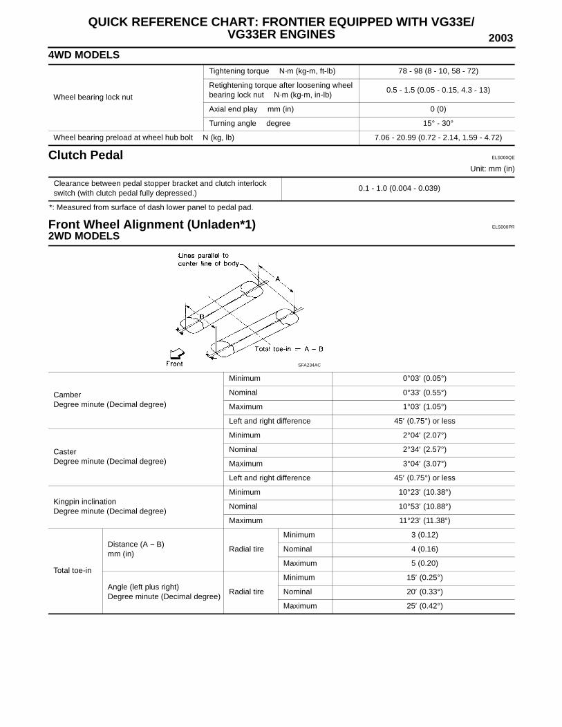
Clutch Pedal ELS000QE
Unit: mm (in)
*: Measured from surface of dash lower panel to pedal pad.
Front Wheel Alignment (Unladen*1) ELS000PR
2WD MODELS
Wheel bearing lock nut
Tightening torque N·m (kg-m, ft-lb) 78 - 98 (8 - 10, 58 - 72)
Retightening torque after loosening wheel bearing lock nut N·m (kg-m, in-lb)
0.5 - 1.5 (0.05 - 0.15, 4.3 - 13)
Axial end play mm (in) 0 (0)
Turning angle degree 15° - 30°
Wheel bearing preload at wheel hub bolt N (kg, lb) 7.06 - 20.99 (0.72 - 2.14, 1.59 - 4.72)
Clearance between pedal stopper bracket and clutch interlock switch (with clutch pedal fully depressed.)
0.1 - 1.0 (0.004 - 0.039)
CamberDegree minute (Decimal degree)
Minimum 0°03′ (0.05°)
Nominal 0°33′ (0.55°)
Maximum 1°03′ (1.05°)
Left and right difference 45′ (0.75°) or less
CasterDegree minute (Decimal degree)
Minimum 2°04′ (2.07°)
Nominal 2°34′ (2.57°)
Maximum 3°04′ (3.07°)
Left and right difference 45′ (0.75°) or less
Kingpin inclinationDegree minute (Decimal degree)
Minimum 10°23′ (10.38°)
Nominal 10°53′ (10.88°)
Maximum 11°23′ (11.38°)
Total toe-in
Distance (A − B)mm (in)
Radial tire
Minimum 3 (0.12)
Nominal 4 (0.16)
Maximum 5 (0.20)
Angle (left plus right)Degree minute (Decimal degree)
Radial tire
Minimum 15′ (0.25°)
Nominal 20′ (0.33°)
Maximum 25′ (0.42°)
SFA234AC
2003QUICK REFERENCE CHART: FRONTIER EQUIPPED WITH VG33E/
VG33ER ENGINES
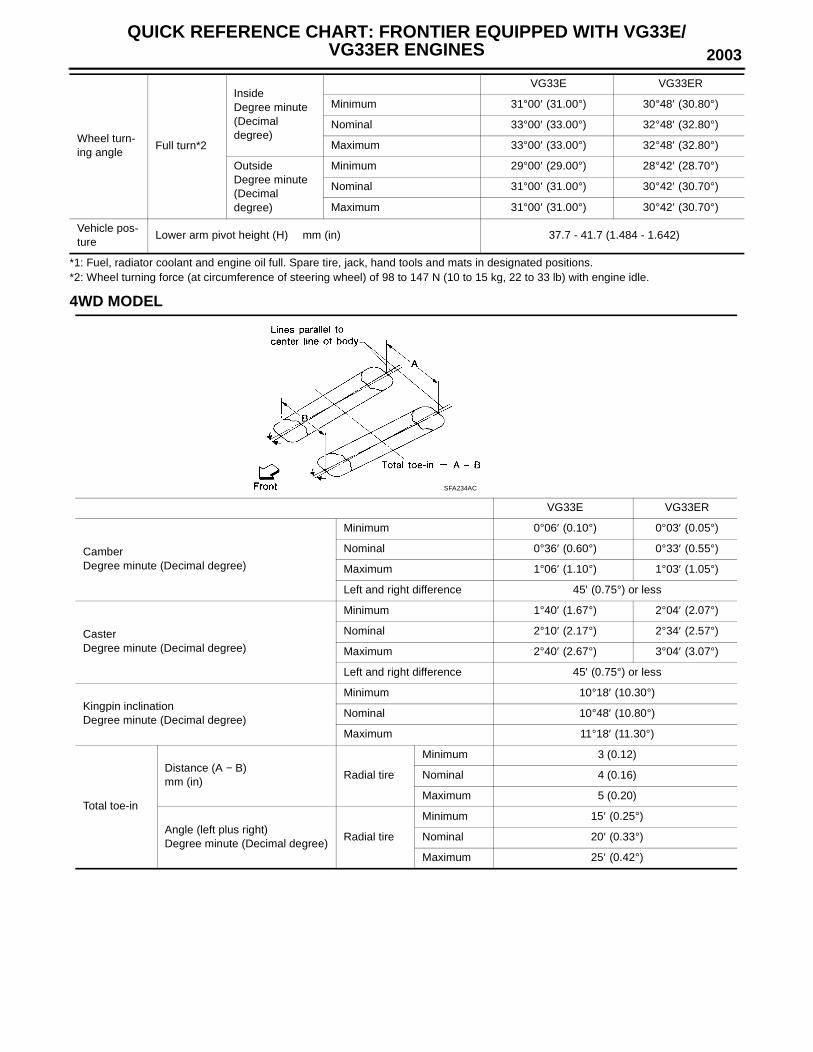
*1: Fuel, radiator coolant and engine oil full. Spare tire, jack, hand tools and mats in designated positions.*2: Wheel turning force (at circumference of steering wheel) of 98 to 147 N (10 to 15 kg, 22 to 33 lb) with engine idle.
4WD MODEL
Wheel turn-ing angle
Full turn*2
InsideDegree minute (Decimal degree)
VG33E VG33ER
Minimum 31°00′ (31.00°) 30°48′ (30.80°)
Nominal 33°00′ (33.00°) 32°48′ (32.80°)
Maximum 33°00′ (33.00°) 32°48′ (32.80°)
OutsideDegree minute (Decimal degree)
Minimum 29°00′ (29.00°) 28°42′ (28.70°)
Nominal 31°00′ (31.00°) 30°42′ (30.70°)
Maximum 31°00′ (31.00°) 30°42′ (30.70°)
Vehicle pos-ture
Lower arm pivot height (H) mm (in) 37.7 - 41.7 (1.484 - 1.642)
VG33E VG33ER
CamberDegree minute (Decimal degree)
Minimum 0°06′ (0.10°) 0°03′ (0.05°)
Nominal 0°36′ (0.60°) 0°33′ (0.55°)
Maximum 1°06′ (1.10°) 1°03′ (1.05°)
Left and right difference 45′ (0.75°) or less
CasterDegree minute (Decimal degree)
Minimum 1°40′ (1.67°) 2°04′ (2.07°)
Nominal 2°10′ (2.17°) 2°34′ (2.57°)
Maximum 2°40′ (2.67°) 3°04′ (3.07°)
Left and right difference 45′ (0.75°) or less
Kingpin inclinationDegree minute (Decimal degree)
Minimum 10°18′ (10.30°)
Nominal 10°48′ (10.80°)
Maximum 11°18′ (11.30°)
Total toe-in
Distance (A − B)mm (in)
Radial tire
Minimum 3 (0.12)
Nominal 4 (0.16)
Maximum 5 (0.20)
Angle (left plus right)Degree minute (Decimal degree)
Radial tire
Minimum 15′ (0.25°)
Nominal 20′ (0.33°)
Maximum 25′ (0.42°)
SFA234AC

QUICK REFERENCE CHART: FRONTIER EQUIPPED WITH VG33E/VG33ER ENGINES 2003
*1: Fuel, radiator coolant and engine oil full. Spare tire, jack, hand tools and mats in designated positions.*2: Wheel turning force (at circumference of steering wheel) of 98 to 147 N (10 to 15 kg, 22 to 33 lb) with engine idle.
Rear Wheel Alignment (Unladen*) ELS000OR
*: Fuel, radiator coolant and engine oil full. Spare tire, jack, hand tools and mats in designated positions.
Brake ELS000Q9
Unit: mm (in)
Wheel turn-ing angle
Full turn*2
InsideDegree minute (Decimal degree)
Minimum 31°00′ (31.00°) 30°48′ (30.80°)
Nominal 33°00′ (33.00°) 32°48′ (32.80°)
Maximum 33°00′ (33.00°) 32°48′ (32.80°)
OutsideDegree minute (Decimal degree)
Minimum 29°00′ (29.00°) 28°42′ (28.70°)
Nominal 31°00′ (31.00°) 30°42′ (30.70°)
Maximum 31°00′ (31.00°) 30°42′ (30.70°)
Vehicle pos-ture
Lower arm pivot height (H) mm (in)45.5 - 49.5 (1.791 -
1.949)37.7 - 41.7 (1.484
- 1.642)
CamberDegree minute (decimal degree)
Minimum −1°45′ (−1.75°)
Nominal −1°00′ (−1.00°)
Maximum −0°15′ (−0.25°)
Total toe-in
Distance (A - B)mm (in)
Minimum −3 (−0.12)
Nominal 1 (0.04)
Maximum 5 (0.20)
Angle (left plus right)Degree minute (decimal degree)
Minimum −16′ (−0.27°)
Nominal 5′30″ (0.09°)
Maximum 26′ (0.43°)
SFA234AC
Front brake
Brake model CL33VD
Cylinder bore diameter × number of pistons 46.4 (1.827) x 2
PadLength × width × thickness
132.0 x 52.5 x 11 (5.20 x 2.067 x 0.43)
Rotor outer diameter × thickness 283 x 28 (11.4 x 1.10)
Rear brake
Brake model LT30A
Cylinder bore diameter 22.22 (7/8)
Lining length × width × thickness296 × 50 × 6.1 (11.65 × 1.97 × 0.240)
Drum inner diameter 295.0 (11.61)
Master cylinder Bore diameter 25.40 (1)

2003QUICK REFERENCE CHART: FRONTIER EQUIPPED WITH VG33E/
VG33ER ENGINES
Disc Brake - Repair LimitsUnit: mm (in)
Drum Brake - Repair LimitsUnit: mm (in)
Refill Capacities ELS000QA
Brake booster
Booster model M230t
Diaphragm diameterPri: 230 (9.06)Sec: 230 (9.06)
Recommended brake fluidGenuine NISSAN Super Heavy Duty Brake Fluid or equivalent DOT 3 (US
FMVSS No. 116)
Brake model CL33VD
Pad Wear limit minimum thickness 2.0 (0.079)
Standard pad thickness 10 (0.39)
Rotor repair limit Minimum thickness 26.0 (1.024)
Rotor runout Maximum 0.07 (0.0028)
Rotor thickness variation Maximum 0.02 (0.0008)
Brake model LT30A
Lining wear limitMinimum thickness 1.5 (0.059)
Standard thickness 5.8 (0.228)
Drum repair limitMaximum inner diameter 296.5 (11.67)
Out-of-round limit 0.03 (0.0012)
Capacity (Approximate)
US measure Imp measure Liter
Engine oilDrain and refill
With oil filter 3 1/2 qt 2 7/8 qt 3.3
Without oil filter 3 1/8 qt 2 5/8 qt 3.0
Dry engine (Engine overhaul) 4 qt 3 3/8 qt 3.8
Cooling system (without reservoir) 10 3/4 qt 8 7/8 qt 10.15
Cooling system reservoir 7/8 qt 3/4 qt 0.8
Manual transmission gear oil (FS5R30A)2WD 3 qt 2 1/2 qt 2.8
4WD 5 3/8 qt 4 1/2 qt 5.1
Transfer fluid (TX10A) 2 3/8 qt 2 qt 2.2
Differential carrier gear oil
Front (4WD)R200A
1 7/8 qt 1 1/2 qt 1.75
RearH233B
3 qt 2 1/2 qt 2.8
Automatic transmission fluid2WD 8 3/4 qt 7 1/4 qt 8.3
4WD 9 qt 7 1/2 qt 8.5
Power steering fluid 33.8-37.2 fl oz35.2-38.7 fl
oz1.0-1.1
Air conditioning system refrigerant HFC 134a (R-134a) 1.32 - 1.54 lb 1.32 - 1.54 lb 0.60 - 0.70 kg
Air conditioning system compressor oil Genuine NISSAN A/C System Lubricant Type R or equivalent
6.8 fl oz 7.0 fl oz 200 m

Attachment No.36
TID CIDP0420 01H 01H Max. 1/128
P0420 02H 81H Min. 1
P0442 05H 03H Max. 1/128mm2
P1442 05H 03H Max. 1/128mm2
EVAP control system purge flow monitoring P0441 06H 83H Min. 20mV
P0456 07H 03H Max. 1/128mm2
P1456 07H 03H Max. 1/128mm2
P0133 09H 04H Max. 16ms
P1143 0AH 84H Min. 10mV
P1144 0BH 04H Max. 10mV
P0132 0CH 04H Max. 10mV
P0134 0DH 04H Max. 1s
P0139 19H 86H Min. 10mV/500ms
P1147 1AH 86H Min. 10mV
P1146 1BH 06H Max. 10mV
P0138 1CH 06H Max. 10mV
P0032 29H 08H Max. 20mV
P0031 2AH 88H Min. 20mV
P0038 2DH 0AH Max. 20mV
P0037 2EH 8AH Min. 20mV
P0400 31H 8CH Min. 1
P0400 32H 8CH Min. 1
P0400 33H 8CH Min. 1
P0400 34H 8CH Min. 1
P1402 35H 0CH Max. 1
P0402 36H 0CH Max. 1count
P0402 37H 8CH Min. 1count
TEST VALUE AND TEST LIMIT (GST ONLY — NOT APPLICABLE TO CONSULT-II)The following is the information specified in Mode 6 of SAE J1979.The test value is a parameter used to determine whether a system/circuit diagnostic test is “OK” or “NG” whilebeing monitored by the ECM during self-diagnosis. The test limit is a reference value which is specified as the
Test limit Conversion
maximum or minimum value and is compared with the test value being monitored.These data (test value and test limit) are specified by Test ID (TID) and Component ID (CID) and can be dis-played on the GST screen.
SRT item Self-diagnostic test item DTCTest value
(GST display)
CATALYST Three way catalyst function
EVAP SYSTEM
EVAP control system (Small leak)
EVAP control system (Very small leak)
EGR SYSTEM
EGR function
EGRC-BPT valve function
HO2S
Heated oxygen sensor 1
Heated oxygen sensor 2
HO2S HTR
Heated oxygen sensor 1 heater
Heated oxygen sensor 2 heater

Attachment No.37
TID CID
P0420 01H 01H Max. 1/128
P0420 02H 81H Min. 1
P0430 03H 02H Max. 1/128
P0430 04H 82H Min. 1
P0442 05H 03H Max. 1/128mm2
P1442 05H 03H Max. 1/128mm2
EVAP control system purge flow monitoring P0441 06H 83H Min. 20mV
P0456 07H 03H Max. 1/128mm2
P1456 07H 03H Max. 1/128mm2
P0133 09H 04H Max. 16ms
P1143 0AH 84H Min. 10mV
P1144 0BH 04H Max. 10mV
P0132 0CH 04H Max. 10mV
P0134 0DH 04H Max. 1s
P0153 11H 05H Max. 16ms
P1163 12H 85H Min. 10mV
P1164 13H 05H Max. 10mV
P0152 14H 05H Max. 10mV
P0154 15H 05H Max. 1s
P0139 19H 86H Min. 10mV/500ms
P1147 1AH 86H Min. 10mV
P1146 1BH 06H Max. 10mV
P0138 1CH 06H Max. 10mV
P0159 21H 87H Min. 10mV/500ms
P1167 22H 87H Min. 10mV
P1166 23H 07H Max. 10mV
P0158 24H 07H Max. 10mV
P0032 29H 08H Max. 20mV
P0031 2AH 88H Min. 20mV
P0052 2BH 09H Max. 20mV
P0051 2CH 89H Min. 20mV
P0038 2DH 0AH Max. 20mV
P0037 2EH 8AH Min. 20mV
P0058 2FH 0BH Max. 20mV
P0057 30H 8BH Min. 20mV
P0400 31H 8CH Min. 1
P0400 32H 8CH Min. 1
P0400 33H 8CH Min. 1
P0400 34H 8CH Min. 1
P1402 35H 0CH Max. 1
P0402 36H 0CH Max. 1count
P0402 37H 8CH Min. 1count
TEST VALUE AND TEST LIMIT (GST ONLY — NOT APPLICABLE TO CONSULT-II)The following is the information specified in Mode 6 of SAE J1979.The test value is a parameter used to determine whether a system/circuit diagnostic test is “OK” or “NG” whilebeing monitored by the ECM during self-diagnosis. The test limit is a reference value which is specified as the
Test limit Conversion
maximum or minimum value and is compared with the test value being monitored.These data (test value and test limit) are specified by Test ID (TID) and Component ID (CID) and can be dis-played on the GST screen.
SRT item Self-diagnostic test item DTCTest value
(GST display)
CATALYST
Three way catalyst function (Bank 1)
Three way catalyst function (Bank 2)
EVAP SYSTEM
EVAP control system (Small leak)
EVAP control system (Very small leak)
HO2S
Heated oxygen sensor 1 (Bank 1)
Heated oxygen sensor 1 (Bank 2)
Heated oxygen sensor 2 (Bank 1)
Heated oxygen sensor 2 (Bank 2)
EGR SYSTEM
EGR function
EGRC-BPT valve function
HO2S HTR
Heated oxygen sensor 1 heater (Bank 1)
Heated oxygen sensor 1 heater (Bank 2)
Heated oxygen sensor 2 heater (Bank 1)
Heated oxygen sensor 2 heater (Bank 2)
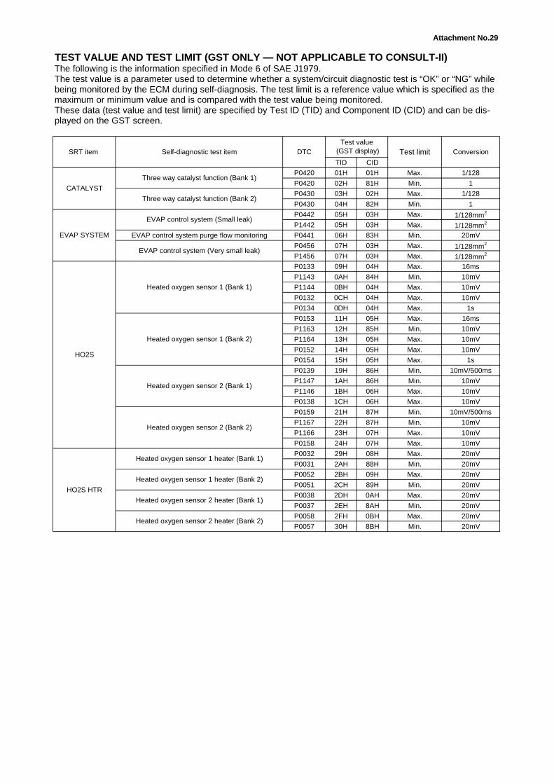
Attachment No.29
TID CID
P0420 01H 01H Max. 1/128
P0420 02H 81H Min. 1
P0430 03H 02H Max. 1/128
P0430 04H 82H Min. 1
P0442 05H 03H Max. 1/128mm2
P1442 05H 03H Max. 1/128mm2
EVAP control system purge flow monitoring P0441 06H 83H Min. 20mV
P0456 07H 03H Max. 1/128mm2
P1456 07H 03H Max. 1/128mm2
P0133 09H 04H Max. 16ms
P1143 0AH 84H Min. 10mV
P1144 0BH 04H Max. 10mV
P0132 0CH 04H Max. 10mV
P0134 0DH 04H Max. 1s
P0153 11H 05H Max. 16ms
P1163 12H 85H Min. 10mV
P1164 13H 05H Max. 10mV
P0152 14H 05H Max. 10mV
P0154 15H 05H Max. 1s
P0139 19H 86H Min. 10mV/500ms
P1147 1AH 86H Min. 10mV
P1146 1BH 06H Max. 10mV
P0138 1CH 06H Max. 10mV
P0159 21H 87H Min. 10mV/500ms
P1167 22H 87H Min. 10mV
P1166 23H 07H Max. 10mV
P0158 24H 07H Max. 10mV
P0032 29H 08H Max. 20mV
P0031 2AH 88H Min. 20mV
P0052 2BH 09H Max. 20mV
P0051 2CH 89H Min. 20mV
P0038 2DH 0AH Max. 20mV
P0037 2EH 8AH Min. 20mV
P0058 2FH 0BH Max. 20mV
P0057 30H 8BH Min. 20mV
TEST VALUE AND TEST LIMIT (GST ONLY — NOT APPLICABLE TO CONSULT-II)The following is the information specified in Mode 6 of SAE J1979.The test value is a parameter used to determine whether a system/circuit diagnostic test is “OK” or “NG” whilebeing monitored by the ECM during self-diagnosis. The test limit is a reference value which is specified as the
Test limit Conversion
maximum or minimum value and is compared with the test value being monitored.These data (test value and test limit) are specified by Test ID (TID) and Component ID (CID) and can be dis-played on the GST screen.
SRT item Self-diagnostic test item DTCTest value
(GST display)
CATALYST
Three way catalyst function (Bank 1)
Three way catalyst function (Bank 2)
EVAP SYSTEM
EVAP control system (Small leak)
EVAP control system (Very small leak)
HO2S
Heated oxygen sensor 1 (Bank 1)
Heated oxygen sensor 1 (Bank 2)
Heated oxygen sensor 2 (Bank 1)
Heated oxygen sensor 2 (Bank 2)
HO2S HTR
Heated oxygen sensor 1 heater (Bank 1)
Heated oxygen sensor 1 heater (Bank 2)
Heated oxygen sensor 2 heater (Bank 1)
Heated oxygen sensor 2 heater (Bank 2)