Embed Size (px)
Citation preview
FRENIC - AceQuick Reference Guide
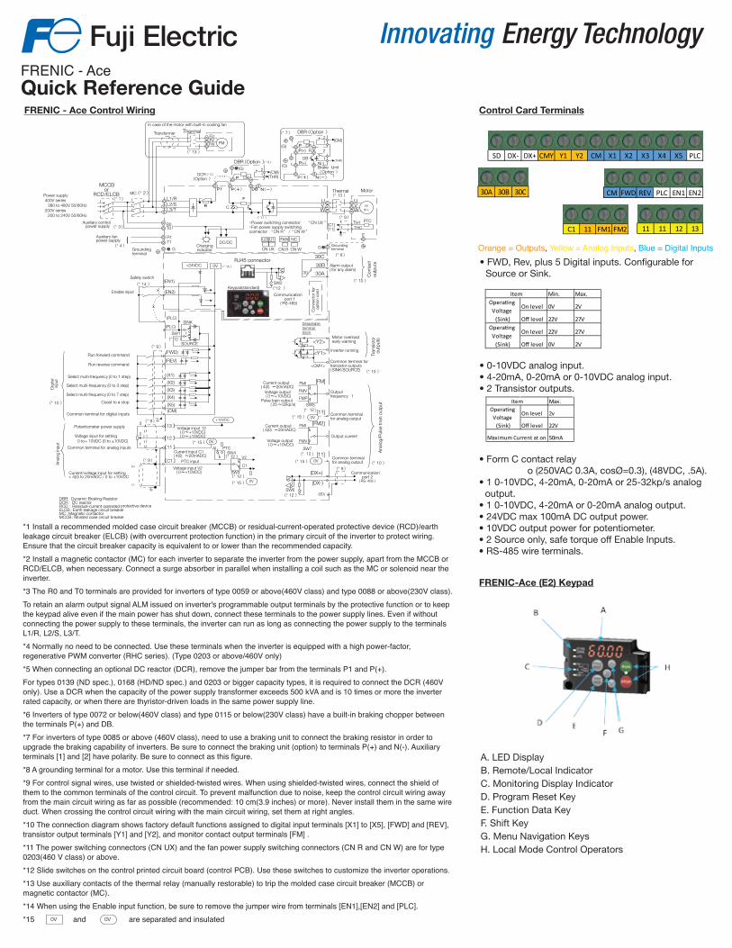
Orange = Outputs, Yellow = Analog Inputs, Blue = Digital Inputs
Control Card TerminalsFRENIC - Ace Control Wiring
*1 Install a recommended molded case circuit breaker (MCCB) or residual-current-operated protective device (RCD)/earth leakage circuit breaker (ELCB) (with overcurrent protection function) in the primary circuit of the inverter to protect wiring. Ensure that the circuit breaker capacity is equivalent to or lower than the recommended capacity.*2 Install a magnetic contactor (MC) for each inverter to separate the inverter from the power supply, apart from the MCCB or RCD/ELCB, when necessary. Connect a surge absorber in parallel when installing a coil such as the MC or solenoid near the inverter.*3 The R0 and T0 terminals are provided for inverters of type 0059 or above(460V class) and type 0088 or above(230V class).To retain an alarm output signal ALM issued on inverter's programmable output terminals by the protective function or to keep the keypad alive even if the main power has shut down, connect these terminals to the power supply lines. Even if without connecting the power supply to these terminals, the inverter can run as long as connecting the power supply to the terminals L1/R, L2/S, L3/T.*4 Normally no need to be connected. Use these terminals when the inverter is equipped with a high power-factor, regenerative PWM converter (RHC series). (Type 0203 or above/460V only)*5 When connecting an optional DC reactor (DCR), remove the jumper bar from the terminals P1 and P(+).For types 0139 (ND spec.), 0168 (HD/ND spec.) and 0203 or bigger capacity types, it is required to connect the DCR (460V only). Use a DCR when the capacity of the power supply transformer exceeds 500 kVA and is 10 times or more the inverter rated capacity, or when there are thyristor-driven loads in the same power supply line.*6 Inverters of type 0072 or below(460V class) and type 0115 or below(230V class) have a built-in braking chopper between the terminals P(+) and DB. *7 For inverters of type 0085 or above (460V class), need to use a braking unit to connect the braking resistor in order to upgrade the braking capability of inverters. Be sure to connect the braking unit (option) to terminals P(+) and N(-). Auxiliary terminals [1] and [2] have polarity. Be sure to connect as this figure.*8 A grounding terminal for a motor. Use this terminal if needed.*9 For control signal wires, use twisted or shielded-twisted wires. When using shielded-twisted wires, connect the shield of them to the common terminals of the control circuit. To prevent malfunction due to noise, keep the control circuit wiring away from the main circuit wiring as far as possible (recommended: 10 cm(3.9 inches) or more). Never install them in the same wire duct. When crossing the control circuit wiring with the main circuit wiring, set them at right angles.*10 The connection diagram shows factory default functions assigned to digital input terminals [X1] to [X5], [FWD] and [REV], transistor output terminals [Y1] and [Y2], and monitor contact output terminals [FM] .*11 The power switching connectors (CN UX) and the fan power supply switching connectors (CN R and CN W) are for type 0203(460 V class) or above.*12 Slide switches on the control printed circuit board (control PCB). Use these switches to customize the inverter operations.*13 Use auxiliary contacts of the thermal relay (manually restorable) to trip the molded case circuit breaker (MCCB) or magnetic contactor (MC).*14 When using the Enable input function, be sure to remove the jumper wire from terminals [EN1],[EN2] and [PLC].*15 and are separated and insulated
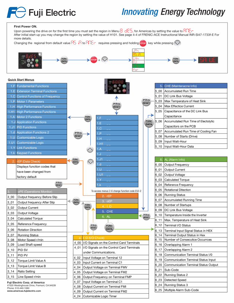
FRENIC-Ace (E2) Keypad
SD DX- DX+ CMY Y1 Y2 CM X1 X2 X3 X4 X5 PLC
30A 30B 30C CM FWD REV PLC EN1 EN2
C1 11 FM1 FM2 11 11 12 13
• FWD, Rev, plus 5 Digital inputs. Con�gurable for Source or Sink.
• 0-10VDC analog input.• 4-20mA, 0-20mA or 0-10VDC analog input.• 2 Transistor outputs.
• Form C contact relay o (250VAC 0.3A, cosØ=0.3), (48VDC, .5A).• 1 0-10VDC, 4-20mA, 0-20mA or 25-32kp/s analog
output. • 1 0-10VDC, 4-20mA or 0-20mA analog output. • 24VDC max 100mA DC output power.• 10VDC output power for potentiometer.• 2 Source only, safe torque off Enable Inputs.• RS-485 wire terminals.
Min. Max.
On level 0V 2V
Off level 22V 27V
On level 22V 27V
Off level 0V 2V
Operating Voltage
(Sink)Operating
Voltage (Sink)
Item
Max.
On level 2v
Off level 22V
Maximum Current at on 50mA
ItemOperating
Voltage (Sink)
A. LED DisplayB. Remote/Local IndicatorC. Monitoring Display IndicatorD. Program Reset KeyE. Function Data KeyF. Shift KeyG. Menu Navigation KeysH. Local Mode Control Operators
R
F
DBR(Option )
DCR(Option )
DB N(-)P(+)P1
UVW
UVW
M3~
C
L1/RL2/SL3/T
MC
MCCBor
RCD/ELCB
GGrounding terminal
(* 1 )
(* 2 )
(* 5 )
( * 6 )
P DB
21 (CM)
(THR)
(G)
N(-)P(+)
P DB
21 (CM)
(G)
2
1 (THR)P(+) N(-)
DBR(Option )
Brake Unit( Option )
(G)P(+) R
DB
(* 7 )
TH1THC
PTC
[11][C1]
Thermal
)
R1T1
R0T0(* 3 )
Auxiliary control power supply
Auxiliary fan power supply
(* 4 ){
(* 11 )
DC/DC
(PLC)
(FWD)
(REV)
(X1)
(X2)
(X3)
(X4)
(X5)(CM)
(EN1)
SINK
SOURCE
(EN2)
0V+24VDC
Run forward command
Run reverse command
Select multi-frequency (0 to 1 step)
Select multi-frequency (0 to 3 step)
Select multi-frequency (0 to 7 step)
Coast to a stop
<Y1>
<Y2>
<CMY>
Inverter running
Motor overload early warning
[FM]
[11]0V
G
E
Output frequency 1
SW1(* 12 )
(* 8 )
(* 9 )
Dig
ital
inpu
t
Common terminal for digital inputs
Con
tact
ou
tput
sTr
ansi
stor
ou
tput
s
(* 10 )
(* 10 )
Common terminal for analog output
Ana
log/
Pul
se tr
ain
outp
ut
Common terminal for transistor outputs( SINK/SOURCE)
Safety switch
SW5(* 12 )
30C
30B
30A
Alarm output( for any alarm)
30
Current output( 4(0) ~20mADC)
Voltage output( 0~+10VDC)
Pulse train output( 25~32kp/s)
・Power switching connector “CN UX ”・Fan power supply switching connector “CN R ” / “CN W ”
(* 10 )
(* 9 )
(* 14 )
(PLC)
Chargingindicator
RJ45 connector
SW2(*12 )
Con
nect
or fo
r op
tion
card
FMI
FMV
FMP
FUFVFW FM
(* 13 )
Transformer
Motor
In case of the motor with built-in cooling fan
Thermal
Communication port 1
( RS-485)
Keypad(standard)
Detachable terminal block
Voltage input V2( 0~+10VDC)
〔11 〕
〔12 〕
〔13 〕(* 9 ) +10VDC
Current input C1( 4(0) ~20mADC)
Current/voltage input for setting + 4(0) to 20mADC / 0 to +10VDC
Voltage input for setting 0 to
+ 10VDC (0 to ±10VDC) 0V
Ana
log
inpu
t
3
2
1
PTC input〔C1〕(* 9 )
(+)
(-)
Voltage input 12( 0~+10VDC)( 0~±10VDC)
SW4PTCAI
(* 12 )
(* 12 )SW3
C1
V2
0V
0V0V
Enable input
DBR: Dynamic Braking ResistorDCR : DC reactorRCD : Residual-current-operated protective deviceELCB : Earth leakage circuit breakerMC : Magnetic contactorMCCB: Molded case circuit breaker
Grounding terminal
Potentiometer power supply
Common terminal for analog inputs
Communication port 2
( RS-485 )
[FM2]
SW7(* 12 )
FMI
FMVOutput current
(DX+)
(DX-)SW6(* 12 ) (SD)
(* 9 )
Current output( 4(0) ~20mADC)
Voltage output( 0~+10VDC)
(* 10 )
[11]0V
Common terminal for analog output
(* 15 )
(* 15 )
(* 15 )
(* 15 )
(* 15 )
U1U2
CN UX
FAN NC
CN R CN W
Power supply 400V series 380 to 480V 50/60Hz 200V series 200 to 240V 50/60Hz
(* 13 )
Fuji Electric Corp. of America47520 Westinghouse Drive, Fremont, CA 94539Phone: 510-440-1060www.americas.fujielectric.com
4. I_O (I/O Check)
4_00 I/O Signals on the Control Card Terminals
4_01 I/O Signals on the Control Card Terminals
under Communications.
4_02 Input Voltage on Terminal 12
4_03 Input Current on Terminal C1
4_04 Output Voltage on Terminal FMV
4_05 Output Voltage on Terminal FM2
4_06 Output Frequency on Terminal FMP
4_07 Input Voltage on Terminal C1
4_08 Output Current on Terminal FMI
4_09 Output Current on Terminal FM2
4_24 Cutomizable Logic Timer
1.F _ _
1.E _ _
1.C _ _
1.P _ _
1.H _ _
1.H1 _ _
1.A _ _
1.J _ _
1.J1 _ _
1.d _ _
1.U _ _
1.U1 _ _
1.Y _ _
1.k _ _
2. rEP
3. oEP
4. I_O
5. CHE
6. AL
5. CHE (Maintenacne Info)
5_00 Accumulated Run Time
5_01 DC Link Bus Voltage
5_03 Max Temperature of Heat Sink
5_04 Max Effectice Current
5_07 Accumulated Run Time of Cooling Fan
5_08 Number of Starts (Drive)
5_09 Input Watt-Hour
5_10 Input Watt-Hour Data
5_05 Capacitance of the DC Link Bus
Capacitance
5_06 Accumutated Run Time of Electolytic
Capacitors on the PCB
6. AL (Alarm Info)
6_00 Output Frequency
6_01 Output Current
6_02 Output Voltage
6_03 Calculated Torque
6_04 Reference Frequency
6_05 Rotational Ditection
6_06 Running Status
6_07 Accumulated Running Time
6_08 Number of Startups
6_09 DC Link Bus Voltage
6_10 Temperature Inside the Inverter
6_11 Max. Temperature of Heat Sink
6_12 Terminal I/O Status
6_13 Terminal Input Signal Status in HEX6_14 Terminal Output Status in Hex6_15 Number of Consecutice Occurrces
6_16 Overlapping Alarm 1
6_17 Overlapping Alarm 2
6_18 Communication Terminal Status I/0
6_19 Communication Terminal Status Input
6_20 Communication Terminal Status Output
6_21 Sub-Code
6_22 Running Status 2
6_23 Detected Speed
6_24 Running Status 3
6_25 Multiple Alarm Sub-Code
Quick Start Menus
1.F Fundamental Functions
1.E Extension Terminal Functions
1.C Control Functions of Frequency
1.P Motor 1 Parameters
1.H High Performance Functions
1.H1 High Performance Functions
1.A Motor 2 Functions
1.J Application Functions
1.J1 PID Functions
1.d Application Functions 2
1.U Customizable Logic
1.U1 Customizable Logic
1.Y Link Functions
1.k Keypad Functions
2. rEP (Data Check)
Displays function codes that
have been changed from
factory default
3. oPE (Operations Monitor)
3_00 Output frequency Before Slip
3_01 Output frequency After Slip
3_02 Output Current
3_03 Output Voltage
3_04 Calculated Torque
3_05 Reference Frequency
3_06 Rotation Direction
3_07 Running Status
3_08 Motor Speed r/min
3_09 Load Shaft speed
3_10 PID SV
3_11 PID PV
3_12 Torque Limit Value A
3_13 Torque Limit Value B
3_14 Ratio Setting
3_15 Line Speed r/min
First Power ON.
Upon powering the drive on for the �rst time you must set the region in Menu 8.des, for Americas by setting the value to amerAfter initial start-up you may change the region by setting the value of H101. See page 4-4 of FRENIC-ACE Instructional Manual INR-SI47-1733f-E For more details.
Changing the regional from default value asia to amer requires pressing and holding key while pressing
jpn
asia
chn
eu
amer
kor
savue+
To access menus 2-6 change function code E52-2


![CCNP BCMSN Quick Reference Sheets - Lagout Quick Reference... · CCNP BCMSN Quick Reference Sheets Exam 642-812 ... [ 4 ] CCNP BCMSN Quick Reference Sheets. ... switch would be used](https://img.dokumen.tips/doc/110x75/5a7a6ec87f8b9a05538dccf5/ccnp-bcmsn-quick-reference-sheets-lagout-quick-referenceccnp-bcmsn-quick-reference.jpg)