Embed Size (px)
Citation preview

Proceedings of the Ninth Annual DARPA Symposium on Photonic Systems for Antenna ApplicationsNaval Postgraduate School, Monterey, CA 17, 18, 19 February 1999
1
Quick Feasibility Demonstration for anInflatable Antenna System in Space
M. L. VanBlaricum, J.P. Reilley, M. A. Gilbert, G. F. VanBlaricum, Jr.Toyon Research Corporation
75 Aero Camino, Suite A, Goleta, CA 93117805-968-6787, [email protected]
D. C. GammonDARPA / STO
3701 N. Fairfax Drive, Arlington, VA 22203
D. P. Cadogan, R. W. Lingo, M. S. GrahneILC Dover, Inc.
One Moonwalker Road, Frederica, DE 19946302-335-3911
W. C. DerbesL’Garde, Inc.
15181 Woodlawn Avenue, Tustin, CA 92780714-259-0771
Abstract
This paper describes a DARPA funded program to test the feasibility of combining very large,lightweight, inflatable, and rigidizable structures with photonic RF data links, flexible broadbandantennas, and flexible solar cells for possible use in large space-based antenna arrays.
1.0 Introduction
Recent Government-funded and commercial programs have significantly improved some keytechnologies:
• Very large, lightweight, inflatable, and rigidizable structures for space applications• Photonic data links and RF/optical transducers• Novel and reconfigurable antenna designs• Flexible solar arrays• Digital beamforming, interference rejection, and element self location in large antenna arrays• High-speed, high-dynamic-range, analog-to-digital (A-D) converters
Ultimately these technologies might be combined into very large array antennas (perhaps manytens or hundreds of meters in length) in space, with the capability to steer multiple simultaneousbeams and adaptively null interference while receiving and relaying to earth digitized signalsover very wide frequency bands. These very large array antennas could have beamwidths of lessthan one degree in the high VHF band, and down to a milliradian or less in the microwave bands.One notional system is sketched in Figure 1, but in fact extremely large structures of manypossible geometries are possible with the inflatable structures technology.

Proceedings of the Ninth Annual DARPA Symposium on Photonic Systems for Antenna ApplicationsNaval Postgraduate School, Monterey, CA 17, 18, 19 February 1999
2
The DARPA / STO fundedfeasibility demonstration programdescribed here makes a first steptoward such a system, combiningseveral of the key technologiesidentified above in a ground-basedexperiment to demonstrate theavailability, compatibility, andfeasibility of combining thesetechnologies. One of the key issuesis the mechanical survivability ofthese technologies during thedeployment of an inflatablestructure.
2 Concept Description2.1 Space Structure
A system such as illustrated inFigure 1 might be deployed from a comparatively small package launched by an expendablebooster. Figure 2 illustrates a possible deployment scheme for the array. The satellite bodywould contain all of the receivers, computers, communication equipment, and power. The onlyattachments to the elements would be fiber-optics lines.
The antenna arms deployed in thisfashion could be extremely long,perhaps greater than 100 meters.Each array arm would be a long,thin, inflatable tube, with antennaelements and solar cells patchedonto the skin. The deflated tubes,along with the fiber-optics links tothe elements, could be rolled up andstored in bays in the satellite body.
The flexibility of the fiber-opticlines would enable them to be rolledup and deployed without damage.By comparison, coaxial cableswould be heavier, bulkier, andexhibit much greater loss. When the bays are opened, the tubes slowly unroll as they are inflatedto low pressure. Once inflated to full size, the flexible tubes would gradually become rigidizedby one of several existing techniques. Eventually the inflation gas would be released, but thetubes retain shape due to rigidization of the tube wall. Any off-nominal deployment of theinflatable structure or any movement of the array structure due to station keeping can becompensated by techniques (e.g., onboard beacons) for self-location of elements.
Figure 1 - Steerable space array concept
Figure 2 - Deployment of array in space
Proceedings of the Ninth Annual DARPA Symposium on Photonic Systems for Antenna ApplicationsNaval Postgraduate School, Monterey, CA 17, 18, 19 February 1999
3
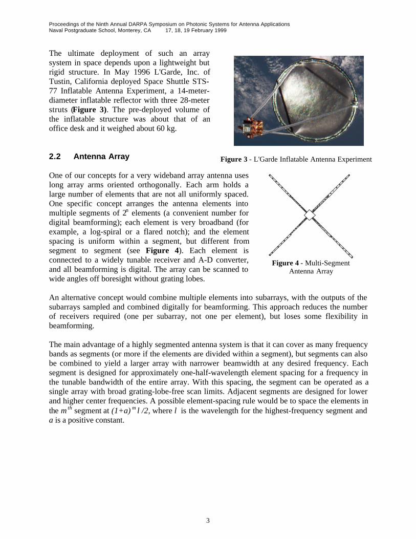
The ultimate deployment of such an arraysystem in space depends upon a lightweight butrigid structure. In May 1996 L'Garde, Inc. ofTustin, California deployed Space Shuttle STS-77 Inflatable Antenna Experiment, a 14-meter-diameter inflatable reflector with three 28-meterstruts (Figure 3). The pre-deployed volume ofthe inflatable structure was about that of anoffice desk and it weighed about 60 kg.
2.2 Antenna Array
One of our concepts for a very wideband array antenna useslong array arms oriented orthogonally. Each arm holds alarge number of elements that are not all uniformly spaced.One specific concept arranges the antenna elements intomultiple segments of 2n elements (a convenient number fordigital beamforming); each element is very broadband (forexample, a log-spiral or a flared notch); and the elementspacing is uniform within a segment, but different fromsegment to segment (see Figure 4). Each element isconnected to a widely tunable receiver and A-D converter,and all beamforming is digital. The array can be scanned towide angles off boresight without grating lobes.
An alternative concept would combine multiple elements into subarrays, with the outputs of thesubarrays sampled and combined digitally for beamforming. This approach reduces the numberof receivers required (one per subarray, not one per element), but loses some flexibility inbeamforming.
The main advantage of a highly segmented antenna system is that it can cover as many frequencybands as segments (or more if the elements are divided within a segment), but segments can alsobe combined to yield a larger array with narrower beamwidth at any desired frequency. Eachsegment is designed for approximately one-half-wavelength element spacing for a frequency inthe tunable bandwidth of the entire array. With this spacing, the segment can be operated as asingle array with broad grating-lobe-free scan limits. Adjacent segments are designed for lowerand higher center frequencies. A possible element-spacing rule would be to space the elements inthe m th segment at (1+a) m λ/2, where λ is the wavelength for the highest-frequency segment anda is a positive constant.
Figure 3 - L'Garde Inflatable Antenna Experiment
Figure 4 - Multi-SegmentAntenna Array

Proceedings of the Ninth Annual DARPA Symposium on Photonic Systems for Antenna ApplicationsNaval Postgraduate School, Monterey, CA 17, 18, 19 February 1999
4
Figure 5 compares the antenna pattern for the shortest 16-element segment with that of an 8-segment, 128-element array. When multiple segments are combined at the same frequency, thearray takes on the characteristics of a thinned array, with many fewer elements than a filled arraywith nominal λ/2 spacing. As a result, its gain is less than a filled array at the same frequencyand the sidelobes are typically somewhat higher, but the angle resolution is the same as the filledarray of the same width.
The frequency coverage of an antenna array andbeamforming system depends upon the desiredapplication. Some types of antenna elements,such as logarithmic spirals, are capable ofcovering a decade of frequency. Hence, the arraycould cover at least the same bandwidth. Anexample might be 200 MHz to 2 GHz. Choosingelements designed for different centerfrequencies could extend the array bandwidtheven more. Although the entire aperture mightnot then be usable at the high and low frequencyextremes, a substantial part of the aperturewould be available at every frequency.
2.3 Photonics and Digital Processing
Each antenna element can be connected to a centralized receiver/digitizer/beamformer via aphotonic link as indicated in Figure 6. This photonic link has many advantages:
• No metallic connections tothe antenna
• Very broad bandwidth• Low loss• Very light weight (key for
space or airborneapplications)
• Mechanical flexibility• Low susceptibility to
electromagneticinterference
The particular link shown uses passive external modulation, with the voltage induced in theantenna modulating the light in the laser link through a Mach-Zehnder interferometer (MZI).Lasers and receivers can be remoted at any convenient distance from the elements. Analternative configuration could use direct modulation. Laser light could deliver power to theelement over a first fiber to a photodiode array, which would then produce DC power. Thispower would then drive an RF amplifier and directly modulated laser to downlink the signal overa second fiber.
Scan Angle (degrees)-30 -20 -10 0 10 20 30
Rel
ativ
e G
ain
(d
B)
-40
-35
-30
-25
-20
-15
-10
-50
Figure 5 - Patterns of single segment (smooth)and eight segments (jagged)
AntennaElement
ExternalOptical
Modulator(MZI)
Fiber
ReceiverPhotodetector
Solid StateLaser
MatchingNetwork /Pre-amp
A / DConverter
Fiber
Equipment Bay
Figure 6 - Photonics link to element and receiver
Proceedings of the Ninth Annual DARPA Symposium on Photonic Systems for Antenna ApplicationsNaval Postgraduate School, Monterey, CA 17, 18, 19 February 1999
5
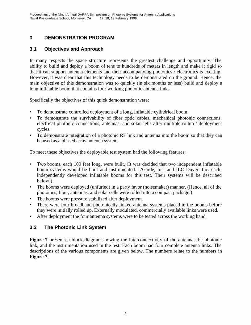
3 DEMONSTRATION PROGRAM
3.1 Objectives and Approach
In many respects the space structure represents the greatest challenge and opportunity. Theability to build and deploy a boom of tens to hundreds of meters in length and make it rigid sothat it can support antenna elements and their accompanying photonics / electronics is exciting.However, it was clear that this technology needs to be demonstrated on the ground. Hence, themain objective of this demonstration was to quickly (in six months or less) build and deploy along inflatable boom that contains four working photonic antenna links.
Specifically the objectives of this quick demonstration were:
• To demonstrate controlled deployment of a long, inflatable cylindrical boom.• To demonstrate the survivability of fiber optic cables, mechanical photonic connections,
electrical photonic connections, antennas, and solar cells after multiple rollup / deploymentcycles.
• To demonstrate integration of a photonic RF link and antenna into the boom so that they canbe used as a phased array antenna system.
To meet these objectives the deployable test system had the following features:
• Two booms, each 100 feet long, were built. (It was decided that two independent inflatableboom systems would be built and instrumented. L'Garde, Inc. and ILC Dover, Inc. each,independently developed inflatable booms for this test. Their systems will be describedbelow.)
• The booms were deployed (unfurled) in a party favor (noisemaker) manner. (Hence, all of thephotonics, fiber, antennas, and solar cells were rolled into a compact package.)
• The booms were pressure stabilized after deployment.• There were four broadband photonically linked antenna systems placed in the booms before
they were initially rolled up. Externally modulated, commercially available links were used.• After deployment the four antenna systems were to be tested across the working band.
3.2 The Photonic Link System
Figure 7 presents a block diagram showing the interconnectivity of the antenna, the photoniclink, and the instrumentation used in the test. Each boom had four complete antenna links. Thedescriptions of the various components are given below. The numbers relate to the numbers inFigure 7.

Proceedings of the Ninth Annual DARPA Symposium on Photonic Systems for Antenna ApplicationsNaval Postgraduate School, Monterey, CA 17, 18, 19 February 1999
6
Figure 7 - Schematic block diagram of photonic / electronic links and instrumentation in test.
1. Computer: A laptop computer with National Instruments PCMCIA-GPIB card and NI-488.2Msoftware for Windows 95.
2. Laser Diode Controller: ILX Lightwave LDC-3900 modular laser diode controller with 4 LCM-39420 combination modules (4) and option-1231 GPIB/IEEE 488.2 interface.
3. GPIB: ILX option-1231 GPIB/IEEE 488.2M interface for the laser diode controller.4. Combination Module: ILX Lightwave LCM-39420 combination module with 200 mA max laser
drive current and –99.9oC to +199.9oC temperature set range.5. Laser Diode Mount: ILX Lightwave LDM-4980 laser diode mount.6. Laser: Philips 20 mW CW 1550 nm GaInAsP DFB laser with integral photo-diode monitor, TE
cooler, and PM fiber pigtail. Typical threshold current: 25mA. Typical differential efficiency: 0.14mW/mA. Typical max bias current: 160mA.
7. Optical Connector: RIFOCS FC/APC optical connectors. Quantity: 19.8. Fiber: Fujikura polarization maintaining singlemode optical fiber.9. Ruggedized Skinny Duplex Cable: Northern Lights Cable, Inc. A two fiber small ruggedized skinny
duplex cable manufactured with one each Corning SMF-28 single mode fiber (13) tight buffered to900 µm and one Fujikura polarization maintaining singlemode optical fiber (8) with no additionaltight buffer. The fibers are parallel served with Kevlar aramid yarn and have a black polyurethanejacket semi pressure extruded overall to a nominal diameter or 2.2 mm.
10. Intensity Modulator: Uniphase Telecommunications Products (UTP) 1550 nm, 2.5 Gbit/s singleoutput electro-optic intensity MZM modulator, with 1m polarization maintaining input and outputfiber pigtails buffered with 900 µm loose tube and terminated with FC/APC connectors. Nominalinsertion loss: 4.2 dB. Nominal RF electrode half-wave voltage: 3.0 V. Nominal bias electrode half-wave voltage: 4.3 V.
11. Antenna: Toyon Research Corporation. Notch antenna (3 each); virtual antenna (1), and bow-tieantenna (4 each).
12. Fiber: Corning SMF-28 singlemode optical fiber.13. Photoreceiver: UTP 2 GHz photoreceiver module. Nominal current draw: 35 mA.14. Power Supply: Hewlett Packard adjustable DC power supply.

Proceedings of the Ninth Annual DARPA Symposium on Photonic Systems for Antenna ApplicationsNaval Postgraduate School, Monterey, CA 17, 18, 19 February 1999
7
Optical Fiber Cables
Five optical fiber cables were built. The booms used four of the cables; a fifth backup cable wasmade in case of a fiber break. The cables had lengths of 75, 100, 125, 150, and 105 ft. Theoptical fibers that connected the laser, modulator, and photoreceiver were comprised of severalcomponents. Polarization maintaining (PM) single-mode fibers (8) connected the lasers (6) andmodulators (10), and non-PM single-mode fibers (12) connected the modulators to thephotoreceivers (13). Wrapping the two fibers in Kevlar Aramid yarn and a polyurethane jacketruggedized them. A meter of fiber was exposed at both ends of the jacket and was protected byonly thin plastic sheathing. This sheathing did not adequately protect the fibers and one fiberbroke while the fiber cable was being installed into the L’Garde boom. The backup cable wasused while the broken cable was repaired.
Both ends of the PM fiber were terminated with FC/APC optical connectors (7). The non-PMfiber was terminated with a FC/APC optical connector on one end, and a Diamond AVIMconnector on the other end. The lasers had FC/APC optical connectors attached to their pigtails.The optical connectors on the modulators were also the FC/APC type. The photoreceiveraccepted AVIM terminated optical fibers.
Laser Control
The heart of the laser control circuitry was the ILX Lightwave LDC-3900 laser diode controller(2). The LDC-3900 had four bays into which laser current control modules and laser temperaturemodules could fit. Four LCM-39420 combination modules (4) were used. These modules couldaccurately control the current and temperature of the lasers. The LDC-3900 also had a GPIBinterface (3), which enabled the laser current and temperature to be monitored and controlled bya computer (1).
The lasers (6) contained a photodiode which monitored the optical power output. The signalproduced by the photodiode was used by the LDC-3900 to control the laser's current to provide aconstant output power. The lasers also contained a thermoelectric cooler and thermistor. Thesignal generated by the thermistor was used by the LDC-3900 to control the temperature of thelaser to provide a constant temperature.
The lasers were mounted on LDM-4980 laser diode mounts (5). These mounts were largealuminum blocks were served as a heat sink and shock absorber for the lasers, and as an interfaceto the LDC-3900. The internal wiring of the mounts was configured for the Philips CQF939/D20lasers.
RF path
The RF signal was captured with the antenna (11), which fed into the modulator (10). Themodulated laser signal traveled through the non-PM fiber (12) to the photoreceiver (13). Thephotoreceiver demodulated the optical signal. The photoreceiver output the RF signal through aSMA connector.

Proceedings of the Ninth Annual DARPA Symposium on Photonic Systems for Antenna ApplicationsNaval Postgraduate School, Monterey, CA 17, 18, 19 February 1999
8
Figure 7 - L’Garde Boom - 100' Long; Root 12”Diameter; Tip 8”.
3.3 L’Garde, Inc. Boom System
Structurally, a tapered boom (conical mast) offersthe potential of reducing boom mass by as muchas 40% with no loss in bending buckling strength.The tapered demonstration boom built by L'Garde(Figure 7) showed that the geometricalcomplexities involved have no adverse impact onantenna performance or fiber optic packaging.
The boom was made of two long neoprene-coatedKevlar gores, aligned and cut on a laser gorecutting table, then tape seamed together using a special straightness fixture. The 11 mil thickmaterial is mechanically similar to the rigidizable materials being proposed for the spacemission.
The antennas placed on the L'Garde boomwere of two types: three broadband taperednotches (Figure 8) and one narrowbandaperture antenna (Figure 9). The narrowbandantenna represents a possible reconfigurabledesign. The antennas consist of copper foilbonded directly to the boom skin. On orbit,RF-transparent multi-layer insulation (MLI)would jacket the boom.
The antenna leads penetrate the boom skin at rigid internal rings(Figure 10), which provide a protective hard mount for the leads,Mach-Zehnder interferometers (MZI), and fiber optic connectors.A cable routing methodology was developed to prevent damageto the delicate fiber optics during packaging and rollout.
The rings are laid flat, and the tube is rolled up for packaging. Inthe mission design, the rings must be spaced at least one to twodiameters apart to accomplish this, but each ring can hold severalMZIs and service several antennas via leads. Therolled-up package is quite compact (Figure 11).
After some initial difficulties with the test setup, thetube was successfully deployed horizontally andsuspended by wires from a long truss (Figure 12).Velcro strips resist the deployment, keeping theinboard section pressure stabilized to handle anydeployment dynamics. These strips would bereplaced by cleaner Ziploc-like strips for flight.
Figure 9 - Narrowband apertureantenna
Figure 8 - Broadband notch array
tube
cablering
Cable taped to tube
Cable thru loop
Cable routed across middle of ring to twist,not bend, when ring is folded down for rollup
Figure 10 - Populated Rings & Fiber OpticRouting

Proceedings of the Ninth Annual DARPA Symposium on Photonic Systems for Antenna ApplicationsNaval Postgraduate School, Monterey, CA 17, 18, 19 February 1999
9
Figure 12 - Boom Antennas Being Tested in RF Chamber
Figure 11 - Rollup Packaging ~21"diameter; 19" width, ~31 lbs
RF tests went smoothly, but we noticedsome boom oscillations, despite theaerodynamic damping. This illustrates theneed for a stiff beam and a quiet spacecraft.Thin-walled large radius tubes are quitestiff, but an even stiffer alternative might bea lightweight truss with inflatablerigidizable longerons.
A basic feature of the boom is the use of lightweight, lowloss fiber optics to carry the signal inboard along such along distance. The same low mass philosophy should applyto the power necessary at each ring. To that end,Lockheed-Martin thin film flexible copper indiumdiselinide (CIS) solar arrays are bonded along the tube(Figure 13), generating power where it is used so that noheavy, lossy distribution wires are necessary. They weretested before and after deployment to demonstrate thatpackaging does not damage them.
3.4 ILC Dover, Inc. Boom System
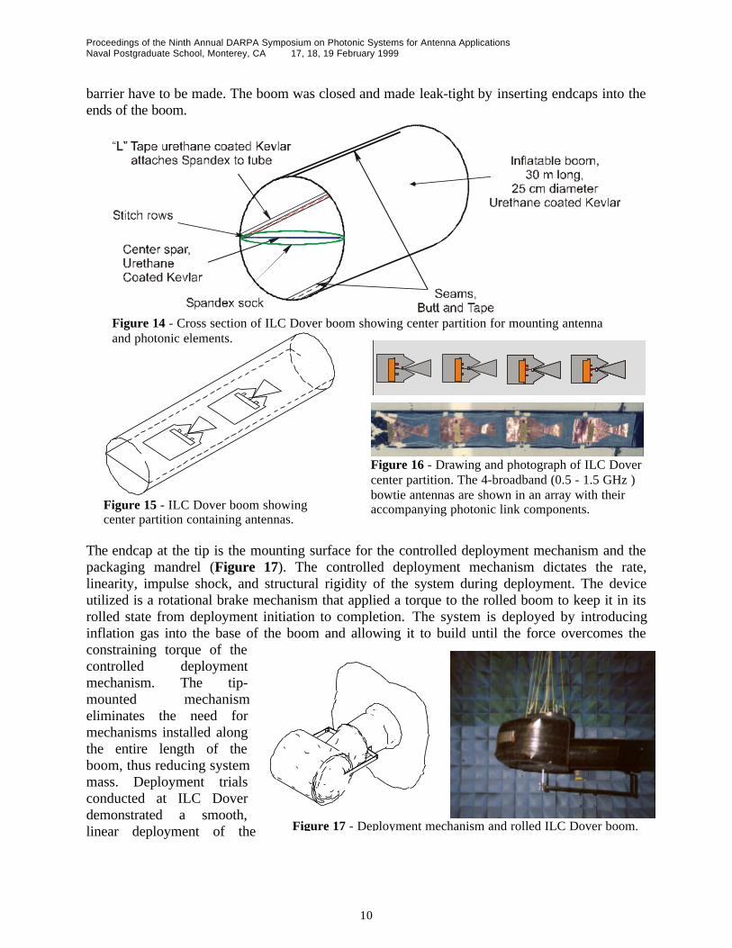
The 30-meter antenna boom manufactured by ILC Dover consisted of a 25-cm diameterinflatable boom with a partition bisecting the tube longitudinally that acts as the mountingsurface for the antenna elements and photonics (Figures 14, 15). The partition allows theantenna elements and photonics to be mounted to a flat surface exposing them to the leastamount of stress and flexing possible during packing and deployment (Figure 16). This increasesthe reliability of the system, simplifies the design, and improves the manufacturability of thedesign. The partition of the boom consists of a carrier that acts as the mounting surface for theantenna components and its interface sleeve that is permanently mounted to the boom’s innerwall. All components are mounted to the carrier and inspected prior to insertion into the boom.This allows the boom to be fabricated, tested and inspected independently from the electronicsportion of the system. By locating all of the antenna elements inside the boom with thephotonics, the reliability of the system is increased because no penetrations of the pressure
Figure 13 -Solar array being tested
Proceedings of the Ninth Annual DARPA Symposium on Photonic Systems for Antenna ApplicationsNaval Postgraduate School, Monterey, CA 17, 18, 19 February 1999
10
barrier have to be made. The boom was closed and made leak-tight by inserting endcaps into theends of the boom.
The endcap at the tip is the mounting surface for the controlled deployment mechanism and thepackaging mandrel (Figure 17). The controlled deployment mechanism dictates the rate,linearity, impulse shock, and structural rigidity of the system during deployment. The deviceutilized is a rotational brake mechanism that applied a torque to the rolled boom to keep it in itsrolled state from deployment initiation to completion. The system is deployed by introducinginflation gas into the base of the boom and allowing it to build until the force overcomes theconstraining torque of thecontrolled deploymentmechanism. The tip-mounted mechanismeliminates the need formechanisms installed alongthe entire length of theboom, thus reducing systemmass. Deployment trialsconducted at ILC Doverdemonstrated a smooth,linear deployment of the
Figure 14 - Cross section of ILC Dover boom showing center partition for mounting antennaand photonic elements.
Figure 16 - Drawing and photograph of ILC Dovercenter partition. The 4-broadband (0.5 - 1.5 GHz )bowtie antennas are shown in an array with theiraccompanying photonic link components.Figure 15 - ILC Dover boom showing
center partition containing antennas.
Figure 17 - Deployment mechanism and rolled ILC Dover boom.

Proceedings of the Ninth Annual DARPA Symposium on Photonic Systems for Antenna ApplicationsNaval Postgraduate School, Monterey, CA 17, 18, 19 February 1999
11
antenna with very low impulse force imparted to the mounting surface. After some initialdifficulties with the test setup, the tube was successfully deployed horizontally and suspended bywires from a long truss (Figure 18).
The boom was manufactured fromurethane coated Kevlar for thedemonstration antenna. This materialwas thermally sealed together usingradio-frequency sealing techniques.The finished boom displayed minimaldeviation from being perfectly straight(<5 cm over 30 meters). Thesematerials were used for thedemonstration model because of theirability to be used in multipledeployments. Flight systems willutilize materials that are “rigidizable”in-situ. The rigidizable materials arecomposite laminates that are packedand deployed in a flexible state andbecome rigid when an outsideinfluence acts on them such as heat orUV radiation. Once the boom isrigidized, inflation gas is vented leaving a solidcomposite structure.
The boom that was tested was populated withflexible solar cells to demonstrate the ability ofgenerating power locally for individual antennacomponents. The cells used were single junctionamorphous silicon cells on a 50 micron polyimidesubstrate available from Iowa Thin FilmTechnologies. The cells were mounted to theexterior of the boom (Figure 19) and cell functionwas demonstrated without decrement before andafter the deployment process.
4.0 Conclusions
This quick (five months from beginning to end) test and demonstration program was designed todemonstrate controlled deployment of two long, inflatable cylindrical booms while at the sametime testing the survivability of integrally mounted fiber optic cables, mechanical photonicconnections, electrical photonic connections, antennas, and solar cells after multiple rollup /deployment cycles. In addition, the tests were designed to demonstrate integration of a photonicRF link and antenna into the boom so that they could be used as a phased array antenna system.All of the components survived the multiple deployments of both of the booms. This is despitethe fact that the initial deployment attempts of both booms were very stressful to the booms.Both phased array antenna systems performed as predicted. The only instability in the results
Figure 18 - ILC Dover's boom about to be set in the testcradle at the Pt. Mugu Radar Reflectivity Laboratory.
Figure 19 - Solar cell array on surface of ILCDover's boom.

Proceedings of the Ninth Annual DARPA Symposium on Photonic Systems for Antenna ApplicationsNaval Postgraduate School, Monterey, CA 17, 18, 19 February 1999
12
was found to be due to a sinusoidal oscillation in the boom. This is not considered a problembecause the technology to track the location of antenna elements on a vibrating boom is well inhand.
As a result of this demonstration program it has been shown that the technologies are matureenough to make very large phased-array antennas in space practical. In particular, the followingconclusions can be drawn.
• Antenna and photonic systems can be packaged, rolled, and deployed in inflatable structureswithout damage.
• Antennas can be placed either inside or outside the inflatable boom effectively. Specificissues relating to placement will depend on ultimate antenna design and connection toelectronics / photonics module.
• Thin film, broadband antennas can be designed and fabricated.• The cylindrical boom can support varied antenna designs - wideband, reconfigurable, narrow
band antennas and array systems.• Solar cells can be mounted on the surface of the inflatable booms and can be rolled and
deployed without damage to the cells.• Making a 100 foot long boom straight is quite feasible and bodes well for longer structures.• Trying to simulate a large boom deployment in a 1-gravity environment is very tricky at best.• Vibration modes generated in the inflated booms seem to be very simple. Hence, they are
easy to remove from array calculation.