Embed Size (px)
Citation preview
Quick Circuit Systems
User’s Manual
Developed and Manufactured by:
5591-B New Peachtree Road Atlanta, GA 30341 TEL (770)455-0676 FAX (770)455-0970 www.t-tech.com [email protected]

Version 3.0
Revision A
Published by:
T-Tech, Inc. 5591 B New Peachtree Road Atlanta, GA 30341
Phone: 770-455-0676 Fax: 770-455-0970 Internet: http://www.t-tech.com [email protected]
Copyright 1990-2001

Dear User:
If you have a suggestion on how a particular aspect of the Quick Circuit System might be improved, please send or e-mail a description of your ideas to T-Tech, Inc. Any thoughts or articles would be appreciated.
Correspondence may be sent to:
T-Tech, Inc. Quick Circuit Technical Support 5591 B New Peachtree Road Atlanta, GA 30341
Tel: 770-455-0676 Fax: 770-455-0970


REGISTRATION SHEET
Thank you for purchasing your Quick Circuit Prototyping System. Please take a few moments to fill out and return this card to T-Tech, Inc. This will ensure that your warranty will be in effect. In addition, by registering as a Quick Circuit end user, T-Tech will be able to supply you with future system updates.
Name ____________________________________________________________
Company Name ____________________________________________________
Address __________________________________________________________
__________________________________________________________
__________________________________________________________
Phone Number _____________________________________________________
Fax Number _______________________________________________________
E-Mail address ____________________________________________________
IsoPro / Isolator Software Serial Number _________________________________ (Labeled on Key)
Quick Circuit Serial Number ___________________________________________
AMC2500 Serial Number _____________________________________________
Mail to: T-Tech, Inc. 5591 B New Peachtree Road Atlanta, GA 30341
Or Fax to: (770) 455-0970


TABLE OF CONTENTS
i
TABLE OF CONTENTS
INTRODUCTION.............................................................................................1
Quick Circuit System Description ...................................................................................... 1
Optional High-Speed Spindle .........................................................................................2
Air Cylinder Configuration...............................................................................................2
Electrical System Description............................................................................................. 2
IsoPro Software Description............................................................................................... 3
BEFORE YOU BEGIN....................................................................................4
Unpacking Check Lists........................................................................................................ 4
Quick Circuit System .....................................................................................................4
Standard Package of Materials ......................................................................................5
Optional Clean Room Vacuum System.........................................................................7
Training.................................................................................................................................. 7
Hardware and Software Contract....................................................................................... 7
Needed Equipment.............................................................................................................. 7
Computer Requirements ...............................................................................................8
INSTALLATION..............................................................................................9
Hardware Installation............................................................................................................ 9
Setting Up Your Computer .............................................................................................9
Connecting the Communication Cables ........................................................................9
Setting up the Air Cylinder............................................................................................10
Connecting the Optional Vacuum System...................................................................11
Setting Up the High-Speed Spindle Power Converter .................................................14
Connecting Power........................................................................................................15
IsoPro Software Installation...............................................................................................15

TABLE OF CONTENTS
ii
ISOPRO SOFTWARE TUTORIAL ............................................................. 17
Overview..............................................................................................................................17
Importing Gerber Data Files .............................................................................................18
Working with Layers...........................................................................................................21
Layer Registration ........................................................................................................22
Saving Your Work...............................................................................................................24
Verifying the Aperture List.................................................................................................25
Editing the Tool Table........................................................................................................26
Changing a Board Entity ..............................................................................................27
Isolating the Layers ............................................................................................................29
Remove Redundant Function ......................................................................................32
Force Isolation Function...............................................................................................34
Expand Pads Function.................................................................................................35
Inspecting the Isolations...............................................................................................36
Rubbing Out the Base Copper .........................................................................................36
Creating the Board Outline................................................................................................38
Creating Text ......................................................................................................................39
"Mill" Drop Down Menu......................................................................................................43
Right-Click Menu................................................................................................................44
Manual configuration of IsoPro Machine Drive ...............................................................45
Additional Features............................................................................................................47
QUICK CIRCUIT SYSTEM OPERATIONS ............................................... 48
Initial System Checkout .....................................................................................................49
Pinning a Board..................................................................................................................52
Drilling Through-Holes using a Drill Press...................................................................52
Drilling Through-Holes using Quick Circuit..................................................................54
Placing a Board on the Milling Table ............................................................................55
Preparing Your *.iso File ...................................................................................................56
Cutting Tools.......................................................................................................................57

TABLE OF CONTENTS
iii
Adjusting the Head Assembly...........................................................................................58
Setting the Upper Travel Limit......................................................................................58
Setting the Lower Travel Limit......................................................................................59
Setting the Vacuum Inlet Tube.....................................................................................59
Setting the Solenoid Stroke..........................................................................................62
Setting the Air Cylinder Travel......................................................................................59
Setting Speed on a the High-Speed Spindle................................................................59
Setting Tool Height.............................................................................................................60
Setting Depth of Cut for Drilling ........................................................................................60
Drilling Your Board.............................................................................................................62
Changing a Tool on a Standard Spindle .........................................................................63
Changing a Tool on a High-Speed Spindle ....................................................................64
Adjusting Depth of Cut for Milling .....................................................................................65
Setting End Mill Depth of Cut .......................................................................................65
Setting the Depth of Cut of a Pointed Milling Tool........................................................66
Milling Your Board..............................................................................................................68
Milling Text and Symbols..............................................................................................69
Adjusting Depth of Cut for Routing ...................................................................................69
Cutting the Board Outline ..................................................................................................70
Finishing Your Board .........................................................................................................70
TROUBLESHOOTING ................................................................................ 71
Diagnostics.........................................................................................................................73
SERVICE AND MAINTENANCE ................................................................ 75
Schedule of Maintenance..................................................................................................75
Lead Screws ................................................................................................................75
Linear bearings.............................................................................................................75

TABLE OF CONTENTS
iv
TECHNICAL TIPS ....................................................................................... 76
Wide Path Milling ...............................................................................................................76
Offsetting the Second Mill Path....................................................................................78
Exporting Files to Fit on the Board Material....................................................................79
Use of Quick Circuit for Engraving ...................................................................................80
APPENDIX A ................................................................................................ 81
Gerber and CAM Essentials .............................................................................................81
APPENDIX B ................................................................................................ 95
License Agreement and Warranty....................................................................................95

INTRODUCTION
1
INTRODUCTION
Congratulations on your purchase of the Quick Circuit system - the fastest, most economical circuit board prototyping system available. This system allows you to produce single- and double-sided circuit boards in about an hour, from standard CAD output files.
The main focus of this manual, however, is the production of circuit boards in the quickest and most cost-effective manner. Please read this manual before you attempt to mill your first board.
If you are attempting your first board, without receiving training from T-Tech, or an authorized dealer, please pay particular attention to the suggestions in this manual. Refer to Training on page 7 for more information.
If problems occur that you are unable to solve, the Technical Support number is (770) 455-0676. It is important to have a phone within reach of the computer and the Quick Circuit system when you call. Also have the serial number of your Quick Circuit machine available before calling technical support.
QUICK CIRCUIT SYSTEM DESCRIPTION The Quick Circuit Model 5000 system is composed of two main assemblies: the milling table with the standard spindle assembly, and the controller. The controller supplies the power to the milling table and acts as the communication link between the table and your personal computer.
Figure 1 - Quick Circuit Main Assemblies

2
INTRODUCTION
2
Some kind of vacuum system is also required for the proper operation of the Quick Circuit system. This can either be your own vacuum setup or one purchased from T-Tech, Inc. The vacuum system is used to remove particles generated by the operation of the Quick Circuit. Proper use of the vacuum will help ensure accurate milling of board features as well as increase tool life.
An optional sound enclosure is also available from T-Tech, Inc. Its purpose is to reduce the amount of noise made during the operation of the Quick Circuit. Through the top panel of the enclosure, you can follow the milling operations on the table, while the front door assembly provides access to the spindle head assembly for tool changes.
Optional High-Speed Spindle
The high-speed spindle option allows you to work with a wider range of speeds, both above and below the speed range of the standard spindle. The advantage of the high-speed spindle becomes evident if you are working with a variety of different board materials.
Air Cylinder Configuration
A solenoid or an air cylinder controls the spindle head assembly. A pneumatic controller regulates the air cylinder on the Quick Circuit. The controller houses an air valve, regulator and pressure gage.

INTRODUCTION
3
ELECTRICAL SYSTEM DESCRIPTION
The Quick Circuit controller connected to your computer and the milling table produces the power to drive the X- and Y- axis stepper motors, the solenoid or air cylinder (depending on your configuration), and the drill (spindle) motor.
The stepper motors turn the lead screws in precise amounts to position the spindle head assembly above the table. The solenoid raises and lowers the spindle above the table. The drill motor rotates the chuck. Signals from the four limit switches on the table are sent back to the computer via the controller.
Computer
Spindle Motor
Z-axis Solenoid
Xmin Xmax Ymin Ymax
X-axis Y-axis Stepper Motors
Limit Switches
AMC2550 Controller
Power in
Figure 2 - Block Diagram of the Quick Circuit System
ISOPRO SOFTWARE DESCRIPTION IsoPro programs the Quick Circuit system to drill, mill and route your circuit board design. The number of computers on which the IsoPro software can be installed depends on the license key you purchased. Only the computer connected to the controller will actually be initialized to run the milling table.
A tutorial for the IsoPro software is provided on page 17 of this manual. The sample files used in the tutorial are on the installation diskettes or CD.
Your CAD design files are translated into Gerber plot files for the CAM process. A general understanding of Computer Aided Manufacturing (CAM) and Gerber files in particular is needed to use the IsoPro software. Refer to the Appendix A: Gerber and CAM Essentials, and Photoplotting Principles for detailed explanations.

BEFORE YOU BEGIN
4
BEFORE YOU BEGIN
UNPACKING CHECK LISTS
Quick Circuit System
If you ordered a Quick Circuit system you should have received the following:
1 Milling table
1 AMC2500 controller
1 37-pin cable
1 Serial computer cable (9-pin female to female NULL modem cable)
1 AC power cord
1 AC power cord adapter for vacuum
Small vacuum hose
1 Vacuum reducer/adapter and silicon plugs
1 Set of IsoPro software installation disks or CD with copy protect key
1 Startup tool kit, that includes
1 3-IN-1 oil can
1 Buff pad
1 1/16" (1,6 mm) Allen wrench for tool changes
1 Package of eight SIP sockets
1 Package of eight dowel pins
1 Package of three set screws
1 Package of two 2.5 A fuses
1 Package of two 8 A fuses
1 Package of tools (10 pieces)
Package of boards (2 pieces)

BEFORE YOU BEGIN
5
If your machine is equipped with an air cylinder, you will also receive the following items:
1 Pneumatic controller
1 5-pin round connector cable
1 AC power cord
Standard Package of Materials
If you purchased the Quick Circuit Standard Package of Materials, you should have received a standard package of tools, including:
Qty Description Part Number
10 Milling tools MILL-T-1
10 Contour routers CR-0062-R2
10 No. 67 Drill bits (0,8 mm) [0.032"] DB-0320
5 No. 60 Drill bits (1 mm) [0.040"] DB-0400
5 No. 53 Drill bits (1,5 mm) [0.0595"] DB-0595
5 0.125 Drill bits (3,2 mm) [0.125"] DB-1250
10 Dowel pins GM-DP-1250
32 SIP sockets Sips
And a standard package of board materials:
AS-KIT-STD for the QC 7000 Model
3 Pieces backup material BM-BACKUP
1 Piece of entry material BM-ENTRY
3 Pieces board material BM-FR 4-1DS
AS-KIT-STD-B for the QC 5000 Model
3 Pieces backup material BM-BACKUP-2
1 Piece of entry material BM-ENTRY-2
3 Pieces board material BM-FR 4-1DS-B

BEFORE YOU BEGIN
6
T-Tech stocks a wide variety of drill bits, milling tools, contour routers, board material, and other supplies. Stocked items are available for same-day shipment. A full catalog is available describing the tools and supplies for use with the Quick Circuit machine. If you do not have this catalog, please call (770) 455-0676 and request a free copy of the Quick Circuit Materials Catalog. This information is also available over the World Wide Web at http://www.t-tech.com.

BEFORE YOU BEGIN
7
Optional HEPA 3 Clean Room Vacuum System
If you purchased a Clean Room Vacuum System you should have received:
1 Vacuum
1 Large 31,75 mm (1 ¼”) inner diameter vacuum hose and hand tools
1 HEPA 3 filter (to remove the fiberglass particles from the air)
2 Black twist ties (with high-speed spindle option only)
TRAINING If you purchased training from T-Tech you should have received one day of training on the Quick Circuit system or an appointment for a future date in which training is to take place. The price does not include travel expenses of T-Tech personnel.
Prior to your training date, you should set up your Quick Circuit system and become familiar with it; this will make the most of your training time. Training will be performed using your files, if possible and can be performed for as many operators as you desire (two or three are recommended).
HARDWARE AND SOFTWARE CONTRACT T-Tech offers an annually renewable service agreement. For specific details and pricing please contact a T-Tech customer support representative

BEFORE YOU BEGIN
8
NEEDED EQUIPMENT You need the following equipment before you can start:
?? A stable workbench
?? 15 amp, 115 Volt standard duplex outlet or a 220-240 VAC, 50/60 HZ power outlet
?? A vacuum source to eliminate board particles (unless you purchased the Clean Room Vacuum System)
?? For machines equipped with an air cylinder, a compressed air source that delivers dry, filtered air at 5,5-10,3 bar (80-150 psi) and 126 ml/sec (3.75 SCFM). Failure to limit the inlet air pressure to 10,3 bar (150 psi) may result in damage to the pneumatic controller
?? An IBM-compatible PC to run the IsoPro software
?? Gerber files and NC (Excellon) drill files generated from your CAD software for the boards that you wish to make
Computer Requirements
The IsoPro software requires:
?? An IBM-compatible PC with a Pentium processor or higher CPU
?? Microsoft Windows 95/98/ME/2000/NT
?? 32 MB of RAM or more
?? 50 MB of free hard disk space
?? A mouse or other pointing device
?? An SVGA graphics card
?? One free 9-pin serial port
INSTALLATION
9
INSTALLATION
HARDWARE INSTALLATION
Setting Up Your Computer
The Quick Circuit controller connects to your computer through an RS-232-C compatible serial communications port. A reliable connection between the controller and the computer's serial port is essential to correct machine operation.
If you have other peripherals (e.g. a mouse) requiring a serial port, then they should be connected to alternate serial ports on your computer. If no alternate ports are available then you will need to purchase and install another card containing serial ports into your computer or do without the use of the peripheral in question while the Quick Circuit is connected.
Before purchasing any additional card for your computer, verify that the card is compatible with your computer and your computer's peripherals.
Connecting the Communication Cables
Follow the steps below to connect the Quick Circuit milling table and controller to your computer.
Step 1: Remove the AMC2500 controller and milling table from the packing material according to the Unpacking Instructions that came with the system. Place them on the workbench, side-by-side. Save all packing materials for warranty work, if needed.
Step 2: If you are using an air cylinder configuration, also unpack the pneumatic controller and cables. Save all packing materials for warranty work, if needed.
Step 3: Place the computer, keyboard, and monitor on or very near the workbench. The pneumatic controller should be placed in an area where the front controls are accessible
Step 4: Make sure that your computer, the controller(s), and any other peripherals are turned off.
Step 5: Connect one end of the provided 9-pin serial cable to the controller and the other end to a serial communications port on your personal computer.
Use only the serial cable provided with the Quick Circuit machine. Do not connect multiple serial cables in series.
INSTALLATION
10
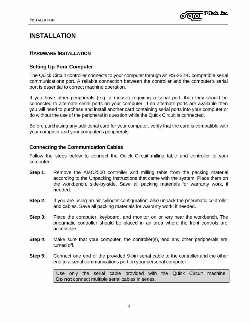
Step 6: Connect the 37-pin communication cable from the back of the controller to the back of the milling table. The cable connector is keyed and will only fit in one way.
Step 7: Connect the 5-pin round connector cable from the back of the pneumatic controller to the back of the AMC2500 controller.
The pneumatic interface connection on the back of the milling table controller is labeled either “Dispenser Interface” or “Options Interface”.
Figure 3 - Connecting Communication Cables
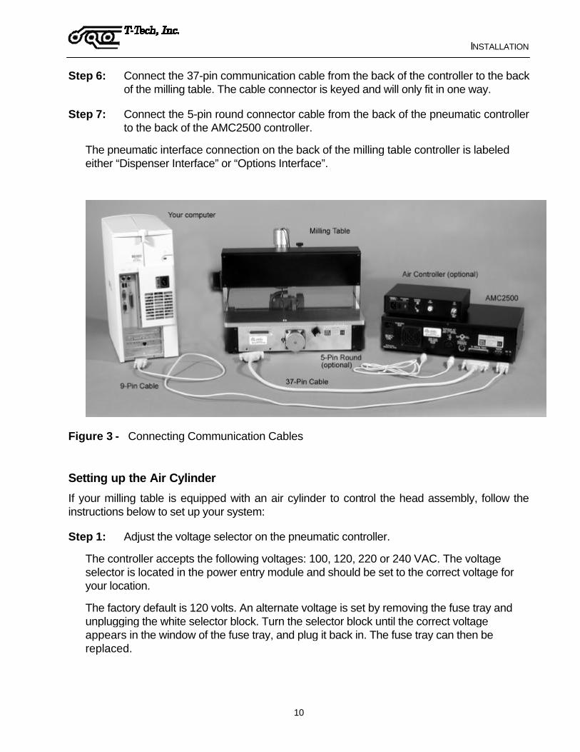
Setting up the Air Cylinder
If your milling table is equipped with an air cylinder to control the head assembly, follow the instructions below to set up your system:
Step 1: Adjust the voltage selector on the pneumatic controller.
The controller accepts the following voltages: 100, 120, 220 or 240 VAC. The voltage selector is located in the power entry module and should be set to the correct voltage for your location.
The factory default is 120 volts. An alternate voltage is set by removing the fuse tray and unplugging the white selector block. Turn the selector block until the correct voltage appears in the window of the fuse tray, and plug it back in. The fuse tray can then be replaced.

INSTALLATION
11
5-pin Connector Air Inlet
Power Entry Module Air Outlet
Fuse Tray
Figure 4 - Back of the Pneumatic Controller
Step 2: Connect the 4 mm (5/32”) polyurethane tube to the speed controller on the air cylinder and route the tube down the vacuum hose. Use the black plastic twist ties to fix the tube to the hose.
Step 3: The tube should then be connected to the air outlet fitting on the back of the pneumatic controller.
To connect the tube to the fittings, simply press the tube into the fitting and gently pull back to ensure that it is properly seated.
To remove the tube, press in on both the tube and the ring and then pull the tube out while continuing to press in on the ring.
The tube can be trimmed to a shorter length if necessary using scissors.
Step 4: Connect the compressed air line to the air inlet on the back of the pneumatic controller using a 6,35 mm (¼”) industrial quick-disconnect fitting.
The inlet air pressure should not exceed 10,3 bar (150 psi). Failure to limit the inlet air pressure to 10,3 bar (150 psi) may result in damage to the pneumatic controller. Adjustments to the air pressure are made later on.
Connecting the Optional HEPA 3 Clean Room Vacuum System
The vacuum system removes particles generated by the milling machine, helps ensure the accuracy of your boards, and prolongs tool life. At the right of the head of the Quick Circuit, is a
INSTALLATION
12
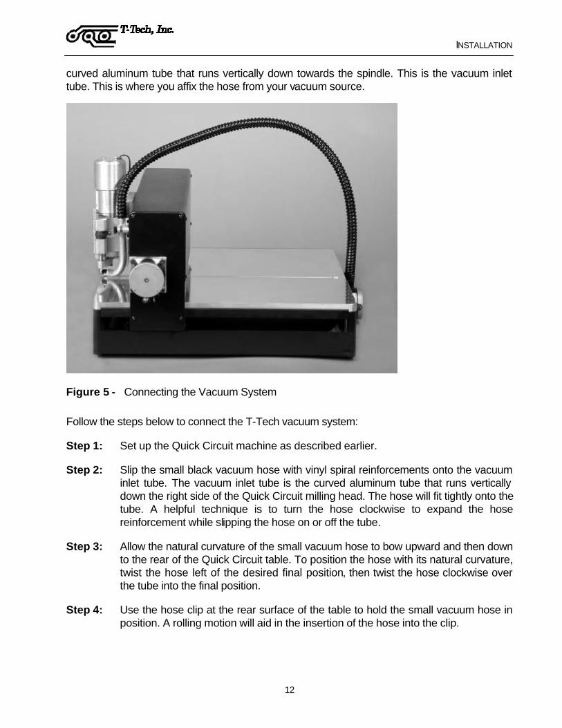
curved aluminum tube that runs vertically down towards the spindle. This is the vacuum inlet tube. This is where you affix the hose from your vacuum source.
Figure 5 - Connecting the Vacuum System
Follow the steps below to connect the T-Tech vacuum system:
Step 1: Set up the Quick Circuit machine as described earlier.
Step 2: Slip the small black vacuum hose with vinyl spiral reinforcements onto the vacuum inlet tube. The vacuum inlet tube is the curved aluminum tube that runs vertically down the right side of the Quick Circuit milling head. The hose will fit tightly onto the tube. A helpful technique is to turn the hose clockwise to expand the hose reinforcement while slipping the hose on or off the tube.
Step 3: Allow the natural curvature of the small vacuum hose to bow upward and then down to the rear of the Quick Circuit table. To position the hose with its natural curvature, twist the hose left of the desired final position, then twist the hose clockwise over the tube into the final position.
Step 4: Use the hose clip at the rear surface of the table to hold the small vacuum hose in position. A rolling motion will aid in the insertion of the hose into the clip.
INSTALLATION
13
Step 5: Check positioning of the small vacuum hose over the full rage of motion of the Quick Circuit by jogging the machine left and right and forward and back. If the hose appears to tighten or restrict motion of the machine, loosen the hose at the rear clip and reposition hose.
Step 6: Set up the vacuum according to the vacuum User’s Manual. The vacuum power cord should be plugged into the AC outlet on the back of the controller and the power switched on. This allows for automatic operation of the vacuum by the Quick Circuit.
Step 7: Remove the hand tool from the large vacuum hose by twisting the hand tool clockwise on the hose. The fit of the hose on the hand tool will be tight at first. Be careful not to crimp the hose. Note that the hand tools are attached to the large vacuum hose by left handed threads. The hand tools are provided in case the user wishes to use the vacuum for conventional uses.
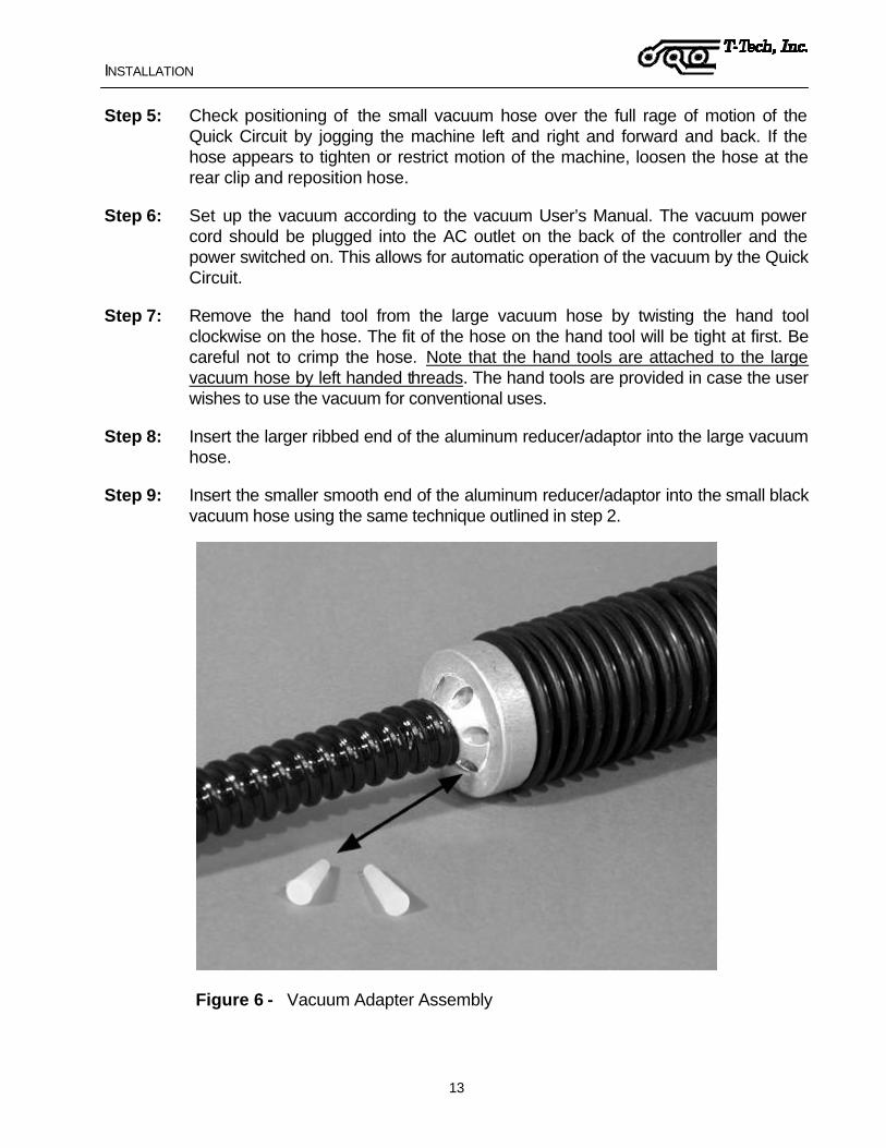
Step 8: Insert the larger ribbed end of the aluminum reducer/adaptor into the large vacuum hose.
Step 9: Insert the smaller smooth end of the aluminum reducer/adaptor into the small black vacuum hose using the same technique outlined in step 2.
Figure 6 - Vacuum Adapter Assembly

INSTALLATION
14
Step 10: Please note that the aluminum reducer/adapter has several bleed holes. The bleed holes can be plugged with the provided silicon tapered plugs to optimize the suction at the vacuum inlet tube depending on your needs. Do not plug all of the holes because the function of the reducer/adaptor bleed holes is to allow air flow for cooling of the vacuum.
Setting Up the High-Speed Spindle Power Converter
The power supply of the AMC2500 controller self-adjusts for input voltage. No setting action is required when the high-speed spindle option is used. However, the spindle's power converter voltage may need to be adjusted.
Step 1: Connect the converter end of the motor power cable to the power converter back panel. Either of the two motor connection points may be used.
Step 2: Connect the motor end of the motor power cable to the motor.
Step 3: Use the two plastic twist ties provided to hold the motor power cable to the small vacuum hose.
Figure 7 - High-Speed Spindle Motor Connections

INSTALLATION
15
Connecting Power
Step 1: Plug the vacuum power cord into the AC outlet on the back of the controller. This allows for automatic operation of the vacuum by the Quick Circuit.
If you are not using a vacuum system provided by T-Tech, Inc, make sure that the electrical requirements of your system are compatible with the maximum current limits noted on the back panel of the controller.
Step 2: If you have an air cylinder on your head assembly, plug the pneumatic controller AC power cord into an available standard outlet.
Step 3: If you have a high-speed spindle assembly, plug the power converter into an available standard outlet.
Step 4: Plug the AMC2500 controller AC power cord into an available outlet, then connect power to your computer.
INSTALLATION
16
ISOPRO SOFTWARE INSTALLATION The IsoPro software is copy-protected with a hardware protection device or key that resides on the computer's parallel port. This software allows users to import their Gerber and Excellon Drill files and calculates the needed isolation or mill paths from the circuit board data.
To install the IsoPro software:
Step 1: Turn on your computer and let it boot up completely.
Step 2: Insert the first IsoPro floppy disk or the CD into your disk drive.
Step 3: Run the Setup program (SETUP.EXE) from within Windows.
Step 4: Follow the instructions in the Setup program.
You will be prompted to select the types of files registered to IsoPro. File types registered to a software application will be identified with the IsoPro icon and can be opened with a double-click.
If you have never used the IsoPro software to create a prototype board, complete the tutorial provided in the next section before continuing.

ISOPRO SOFTWARE TUTORIAL
17
ISOPRO SOFTWARE TUTORIAL
OVERVIEW This tutorial provides a training procedure for using T-Tech’s IsoPro software. The sample case involves a typical design with a component side, a solder side and a drill file. This tutorial describes how to:
?? Load your CAD data (importing Gerber files)
?? Mirror the solder side
?? Register the component and solder sides (for this tutorial the component and solder layers are purposefully input as Gerber files that do not register with each other)
?? Correctly size the tools required by editing the Tool Table
?? Perform a clearance test
?? Perform a 0,25 mm (0.010“) and a 0,78 mm (0.031”) isolation (for use as a mill path to outline all of the pads and traces on the board)
?? Perform a 0,78 mm (0.031”) rubout that can also be used as a mill path to remove all excess copper
?? Create a board outline
The hardware protection device [dongle] must be installed on the computer’s printer port in order to fully use IsoPro.
To actually machine the board, follow the instructions in on page 48.
ISOPRO SOFTWARE TUTORIAL
18
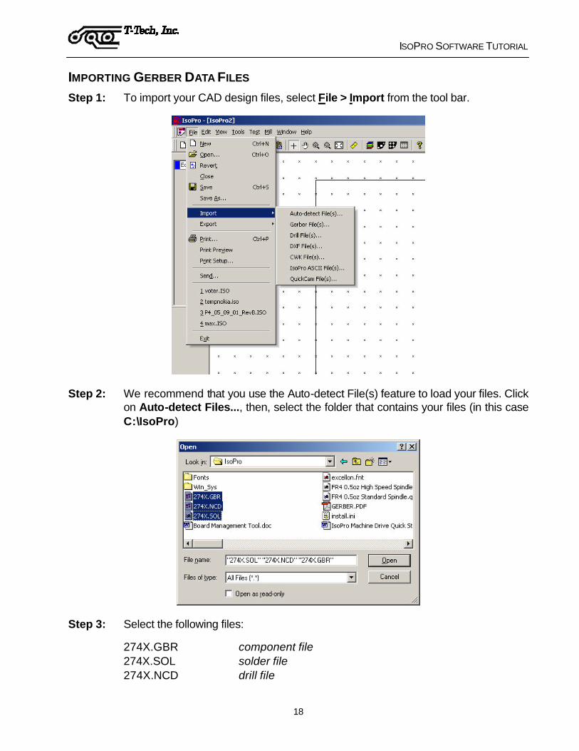
IMPORTING GERBER DATA FILES Step 1: To import your CAD design files, select File > Import from the tool bar.
Step 2: We recommend that you use the Auto-detect File(s) feature to load your files. Click on Auto-detect Files..., then, select the folder that contains your files (in this case C:\IsoPro)
Step 3: Select the following files:
274X.GBR component file 274X.SOL solder file 274X.NCD drill file

ISOPRO SOFTWARE TUTORIAL
19
To import all three files at the same time, hold down the CTRL key and click on each file.
Step 4: Click Open. The Auto Import window lists various parameters; including board dimensions (file extents), whole digits, precision digits, and zero suppression methods.
change screen capture to show the 6 x 3 board that we will be using
You can identify the correct parameters by noting the file extents, which are approximately the same as the board size.
Step 5: Double-click on the file extents that represent the approximate size of your board. For our purposes, select a board size of 6.0 x 3.0 inches using 4.3 absolute mode and leading zero suppression.
When using your own CAD files, rather than the samples provided with this tutorial, select the file extents closest to the size of your circuit board data. Please note that file extents are approximate only. The Auto-detect File(s) feature does a quick estimate rather than an exact calculation of the board size.

ISOPRO SOFTWARE TUTORIAL
20
You may also bring in your file by using File > Open on the toolbar and specifying the import settings.
IsoPro also has an optional DXF import feature. If your IsoPro software is licensed for DXF import, click on File > Import > DXF File(s)... to import DXF data.
A single DXF file often contains all the layers of a circuit board. IsoPro automatically imports each imbedded layer separately. Use the Layer List (explained hereafter) to identify your layers as ‘Component’, ‘Solder’, or ‘Drill’ as appropriate.
Layers containing unnecessary information, such as unwanted text, should simply be set to ‘Hide’.

ISOPRO SOFTWARE TUTORIAL
21
WORKING WITH LAYERS
IsoPro imports each file into a separate layer represented by a different color. Layers enable you to separate the component, solder, and drill information so that you can edit one without affecting the others.
The Layer List icon looks like a stack of four sheets of colored paper. When clicked, it brings up the Layer Table. From here, you can change the layer color, name, status, and type. You can also specify whether the layer is mirrored and define the aperture table to use.
Layer Palette in the left margin of the screen displays the same colors as the ones shown in the Layer Table. This is an easy way to identify data on your screen. Changing a layer color in the Layer Table also changes it in the Layer Palette.
Set the following layer types for the tutorial files imported earlier:
set 274X.gbr to Component
set 274X.sol to Solder
Notice that 274X.ncd is already identified as Drill and that the layer type defined as Solder is automatically marked as ‘Mirror’.

ISOPRO SOFTWARE TUTORIAL
22
Mirroring here refers only to the files that are output for use with the Quick Circuit machine. On the screen in IsoPro, all layers are displayed as viewed from the component side of the board. When a layer is mirrored, it means that all future work on the particular layer will also be mirrored automatically.
There are three possible status modes. They are:
View - Allows you to see the layer, but not edit the data. This is helpful when using a layer as a logical reference.
Edit - Allows you to modify, select, delete, mirror, and edit the data on the layer.
Hide - Allows you to hide the layer to prevent confusion while working on other layers.
While in the Layer Table, you can also add a new layer, copy an existing layer, or delete unnecessary layers.
Layer Registration
Purpose: To align the layers so that they line up (register) with one another.
For this tutorial, we purposefully created a component and solder side that did not line up with each other.
Inspect your CAD files to determine if the solder side is mirrored. If your solder side is not mirrored, the holes on each layer will NOT line up.
In the following procedure, you will first hide your drill layer since you will not be working with it for now. Then you will set the status for the component layer to View and verify that the status of the solder side layer is set to Edit.
Use the following steps to register each layer:
Step 1: Set the 274.ncd layer to Hide. It is already registered so there is no need to display it at this time.
Step 2: We will be moving the solder data to register with the component data so set the component layer 274x.gbr to View so we do not change it.
Step 3: Set the 274x.sol layer to Edit and make sure the Mirror check box is selected. The only data that can now be edited is the solder layer.
Note: You can also change the status of the layers (i.e. Edit, View, Hide) by left clicking on that layer in the Layer Palette.
Step 4: Close the Layer Table.

ISOPRO SOFTWARE TUTORIAL
23
Step 5: Use your mouse to click and drag a box around the entire solder file (you can also use Edit > Select All or press Ctrl+A).
Release the mouse. The color of the selected data is now gray and is indicated by white squares called “handles”.
Step 6: The next step is to mirror the board. Click on the Mirror icon.
Step 7: Click on the Layer Registration icon to select the Register tool.
ISOPRO SOFTWARE TUTORIAL
24
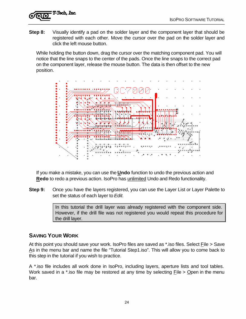
Step 8: Visually identify a pad on the solder layer and the component layer that should be registered with each other. Move the cursor over the pad on the solder layer and click the left mouse button.
While holding the button down, drag the cursor over the matching component pad. You will notice that the line snaps to the center of the pads. Once the line snaps to the correct pad on the component layer, release the mouse button. The data is then offset to the new position.
If you make a mistake, you can use the Undo function to undo the previous action and Redo to redo a previous action. IsoPro has unlimited Undo and Redo functionality.
Step 9: Once you have the layers registered, you can use the Layer List or Layer Palette to set the status of each layer to Edit.
In this tutorial the drill layer was already registered with the component side. However, if the drill file was not registered you would repeat this procedure for the drill layer.
SAVING YOUR WORK At this point you should save your work. IsoPro files are saved as *.iso files. Select File > Save As in the menu bar and name the file “Tutorial Step1.iso”. This will allow you to come back to this step in the tutorial if you wish to practice.
A *.iso file includes all work done in IsoPro, including layers, aperture lists and tool tables. Work saved in a *.iso file may be restored at any time by selecting File > Open in the menu bar.

ISOPRO SOFTWARE TUTORIAL
25
VERIFYING THE APERTURE LIST Purpose: To verify the aperture shapes and sizes used to draw your circuit board’s pads
and traces.
To view the aperture list, click the Aperture List icon on your tool bar. You should verify that your aperture list is correct for your circuit board.
In this tutorial, the imported files use the RS274-x standard. This means that all the apertures were imported directly without intervention from the user. T-TECH STRONGLY RECOMMENDS USING RS274-X FORMAT. Most CAD packages released since 1995 support this format.
If your files do not use RS274-X, and you do not have an aperture list loaded, you will notice that your aperture dimensions default to 9.99 and 49.99. This is a very distinctive size and will probably never be used on a circuit board. If you see these values in your list, manually edit the aperture widths to match the output of your CAD package. Most CAD packages, when not using RS274-X, output the aperture list as a separate report file.

ISOPRO SOFTWARE TUTORIAL
26
EDITING THE TOOL TABLE Purpose: To verify the tool sizes used to make your circuit board.
Click on the Tool Table icon on the tool bar. The tool table usually imports into IsoPro automatically, but on occasion it may not. In that case you must edit the data manually.
change these screen captures to show current tool table information
If your tool sizes default to 49.99 mils or 1.27 mm, this is a flag that indicates these are the default values. For this tutorial, simply set Tool 1 to 0,78 mm (31.00 mils) and Tool 2 to 1 mm (40.00 mils). Notice how IsoPro automatically selects the appropriate RPM and Mill Speed for the selected tool.
However, for your own applications, you should always match the sizes of the holes in your board to those that your CAD package outputs. These sizes can be determined by either looking at a report file that was output by your CAD package or looking at the header of the drill file itself. If they are in the header of the drill file, you can view it by opening the file using a simple text editor.

ISOPRO SOFTWARE TUTORIAL
27
Changing a Board Entity
At times, it may be necessary to manually change the size of an entity in IsoPro. Notice how the default entity size of 49.99 mils in this tutorial makes the drill hole oversized. To change the entity, follow the steps below.
Step 1: Place the mouse over the entity to be changed and right click. This will reveal a drop down box. Select Properties.
Step 2: The Entity Properties dialog box appears.
‘D’ codes refer to the entities such as pads and traces, ‘T’ codes refer to the tool sizes.
In this example we are going to change the ‘T’ code (tool size). When a drill hole is centered on a pad, the entity [pad] will be shown first, and the drill size follows. Select OK until you reach the tool size window you want.

ISOPRO SOFTWARE TUTORIAL
28
In some cases there will be two entities buried on top of each other. In this case, IsoPro will iterate through both entities. Changing the properties of an entity in this manner will not be necessary if the files from your CAD package are correct. (However, if you want to do some last minute editing without going back to your CAD package you can change the size or shape of a single pad or trace using this method. No other pads or traces will be affected.)
Step 3: Change the diameter of this hole from 49.99 mils to 0,78 mm (31.00 mils) as shown above, and then select OK. The resulting change in the drill hole is shown below.
Step 4: Repeat these steps for each entity you wish to change.
Always remember to change your CAD file accordingly. Otherwise, your prototype board will be correct, but your production boards may not.
ISOPRO SOFTWARE TUTORIAL
29
ISOLATING THE LAYERS Purpose: To create an outline around the pads and traces of your design so that a circuit
board prototyping system can produce your board.
Now that you have verified that your aperture list and files are correct, you need to isolate the component and solder layers.
Step 1: Set the status of the drill and solder layers to Hide.
This is not a required step. However, it can help prevent mistakes and makes your first few board designs run a little smoother.
Another way is to set the solder and drill layers to View. The important thing is to make sure that only the layer you wish to have in action is in Edit mode.
Step 2: Determine the minimum clearances for pad-to-pad, pad-to-trace, and trace-to-trace distances.
The initial isolation cannot exceed the minimum clearance. You can determine the minimum clearances in your circuit in IsoPro manually using the measure function or by using the Clearance Check function. Alternatively, you may already know this from your CAD software.
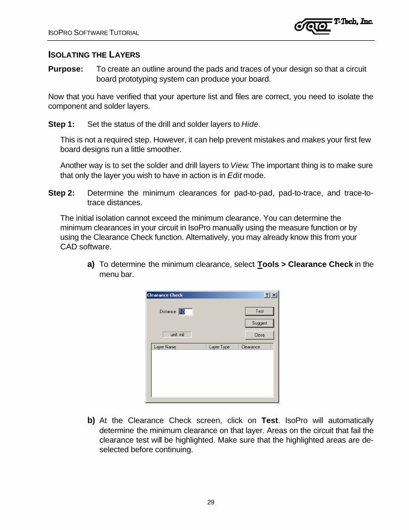
a) To determine the minimum clearance, select Tools > Clearance Check in the menu bar.
b) At the Clearance Check screen, click on Test. IsoPro will automatically determine the minimum clearance on that layer. Areas on the circuit that fail the clearance test will be highlighted. Make sure that the highlighted areas are de-selected before continuing.

ISOPRO SOFTWARE TUTORIAL
30
IsoPro calculated that the minimum clearance for the component layer at 0,34 mm (13.5 mils).
For the purposes of this tutorial, we will do the initial isolation with a 0,25 mm (10 mil) tool, followed by a 0,78 mm (31 mil) tool. It is necessary to perform an isolation with a tool size equal to or less than the minimum clearance so that all of the nets in your circuit are properly isolated.
Choosing a diameter that is too large will result in the merging of nets on your board. For easier solderability, a larger second pass, in this case 0,78 mm (31 mils or 0.031”), is recommended.
This is typically all that is required for a digital board but please note that IsoPro can perform up to three different size isolations simultaneously.
Step 3: Click on Tools > Isolate in the menu bar.
Enter 0,25 mm (0.010”) for Pass 1 and 0,78 mm (0.031”) for Pass 2. Set Pass 3 to zero which indicates that this pass is not used.
Note: Tool sizes can be entered in inches or metric mode [mm]. Metric mode can be selected from Edit > Preferences in the menu bar.
Step 4: Select the component and solder layer by holding down the CRTL key while selecting both layers.
Step 5: Click on the Isolate button.

ISOPRO SOFTWARE TUTORIAL
31
You will see different color representations (or shades of gray if you did not print this manual in color) of the defined mill paths for both the component and solder layers once the isolation process is completed.
Notice that four additional layers are shown on the Layer Palette. Click on the Layer icon to see the definitions for these new layers.
When IsoPro creates the isolation layers, it automatically lists them by tool size. In addition, it defines all isolation layers for the solder layer as mirrored. (This occurs only if you selected Solder as the layer type.)

ISOPRO SOFTWARE TUTORIAL
32
IsoPro also provides several special options for use during the isolation routine. These are Remove Redundant, Force Isolation and Expand Pads.
Remove Redundant Function
Remove Redundant locates and deletes those sections of the smaller tool isolations, which are completely overlapped by larger isolation paths. On some types of circuit boards, the use of Remove Redundant can offer significant savings in machine time and tool wear.
The Remove Redundant option is enabled and disabled in the Isolation dialog box.
In the illustration above, we are isolating only the component Layer by setting the solder layer to Hide and the drill layer to View. We are making two isolations and have enabled the Remove Redundant feature by checking the applicable box in the Isolation dialog.
Enabling the Remove Redundant option prevents redundant isolations from occurring (as shown in the figure on the left). The red (or darker gray) represents the 0,25 mm (10 mil) isolation path. It only appears in those areas where the subsequent isolation, in this case the 0,78 mm (31 mil) represented by the light green (or lighter shade of gray), cannot effectively

ISOPRO SOFTWARE TUTORIAL
33
remove the required copper. Without the Remove Redundant feature, your isolation paths appear as shown in the figure on the right.

ISOPRO SOFTWARE TUTORIAL
34
Force Isolation Function
If the clearance between entities is less than the smallest tool size available, it is still possible to isolate your layer by using the Force Isolation function. Force Isolation is a feature that allows you to specify a tool width that exceeds the stated gap distance between pads/traces. Under normal circumstances, IsoPro will not allow a tool diameter to pass through a gap that is smaller than the specified tool diameter.
The use of Force Isolation can be risky and therefore is not available by default in the Isolation dialog box. Original CAD data can be destroyed when using this function. Because of the potential for the destruction of data, Force Isolation is not available by default. You can select it through Edit > Preferences and selecting the Advanced tab.
show screen capture with Force isolation selected, and Remove Redundant deselected...
Select your tool size and Force Isolation in the Isolation dialog box when you are ready to isolate a specific layer. Check the results carefully to make sure that the isolation path does not create short circuits on your board.
ISOPRO SOFTWARE TUTORIAL
35
Expand Pads Function
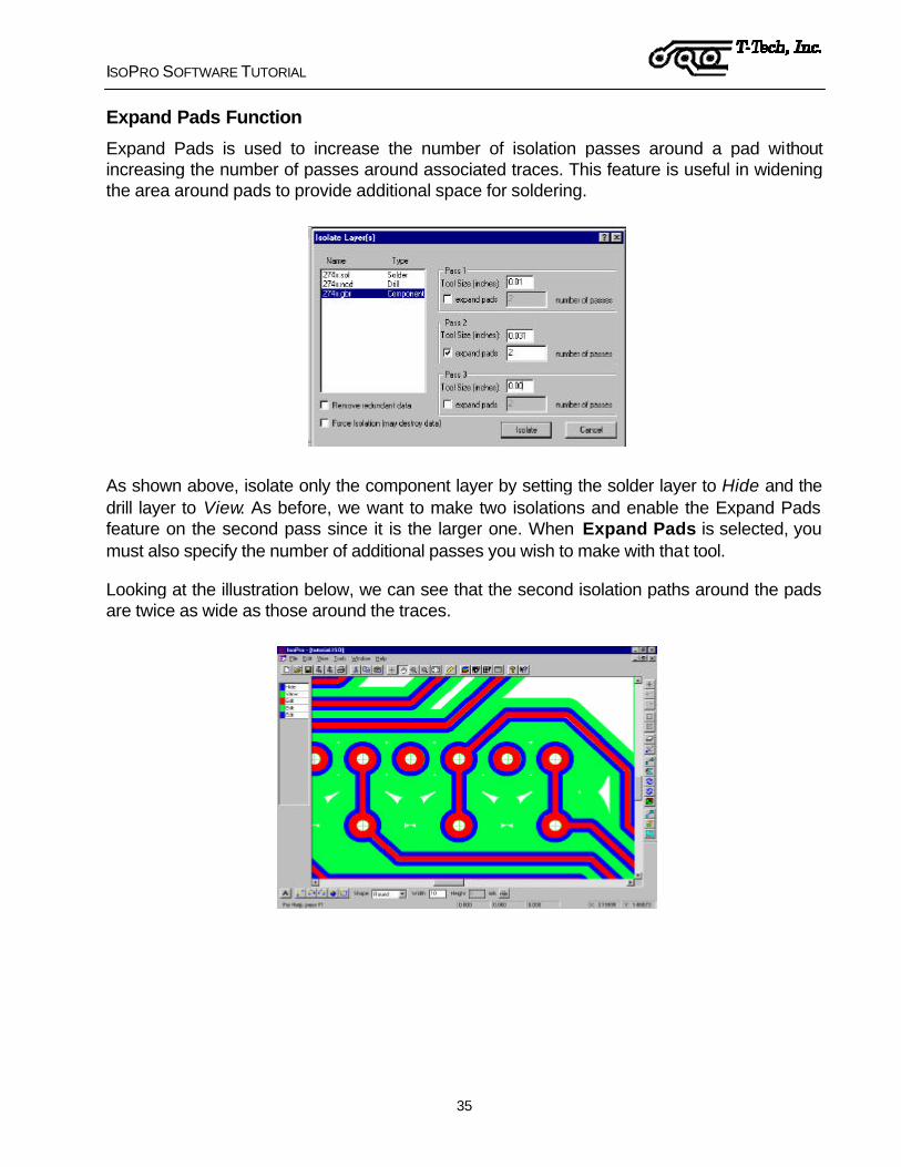
Expand Pads is used to increase the number of isolation passes around a pad without increasing the number of passes around associated traces. This feature is useful in widening the area around pads to provide additional space for soldering.
As shown above, isolate only the component layer by setting the solder layer to Hide and the drill layer to View. As before, we want to make two isolations and enable the Expand Pads feature on the second pass since it is the larger one. When Expand Pads is selected, you must also specify the number of additional passes you wish to make with that tool.
Looking at the illustration below, we can see that the second isolation paths around the pads are twice as wide as those around the traces.
ISOPRO SOFTWARE TUTORIAL
36
Inspecting the Isolations
It is a good idea to zoom in and inspect the isolation to make sure it was done properly. You should see a clean outline around each electrical net.
Use the zoom-in cursor on the tool bar to drag a window around an area of interest.
Use the pan-hand feature to move around and inspect the data.
If the isolation path is not completely defined around each entity on your board, or if the isolation path is too large as a result of using the Force Isolation feature, the board will not be electrically correct. Use a smaller tool size and repeat the Layer Isolation procedure as needed.
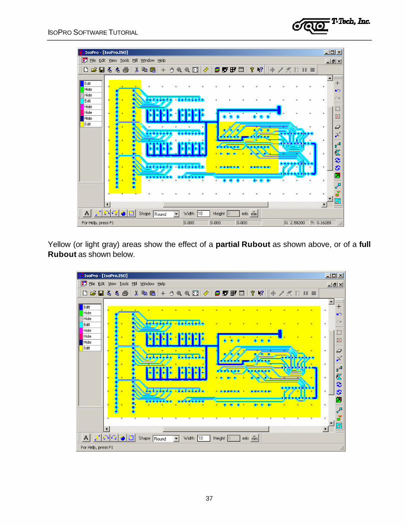
RUBBING OUT THE BASE COPPER The Rubout feature allows you to remove an area of unwanted copper in a single function. Ordinarily, you would not perform a rubout on a digital board; however, if you have a set of fingers (for an edge connector) or an SMT component that requires a rubout, you can take off copper from a particular part of the board, several specific areas of the board or the entire board. The Rubout feature can be useful for many RF/MW applications.
You can also modify the rubout area by using the “Ball & Stick” mode under View in the menu bar, then selecting unwanted portions of the rubbed out area and deleting them. The “Ball and Stick” view mode allows you to see the exact path of the rubout tool.
Rubout only works one layer at a time. If you want to perform a rubout on both the component and solder layers, you must repeat this procedure for each side.
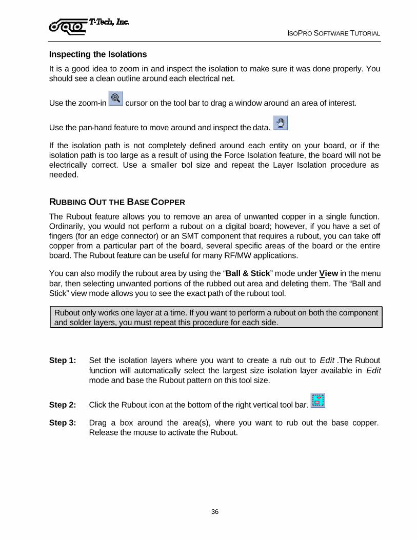
Step 1: Set the isolation layers where you want to create a rub out to Edit .The Rubout function will automatically select the largest size isolation layer available in Edit mode and base the Rubout pattern on this tool size.
Step 2: Click the Rubout icon at the bottom of the right vertical tool bar.
Step 3: Drag a box around the area(s), where you want to rub out the base copper. Release the mouse to activate the Rubout.
ISOPRO SOFTWARE TUTORIAL
37
Yellow (or light gray) areas show the effect of a partial Rubout as shown above, or of a full Rubout as shown below.

ISOPRO SOFTWARE TUTORIAL
38
CREATING THE BOARD OUTLINE Purpose: To create an outline of your board.
You can import the board outline from your CAD package or create it in IsoPro. Using IsoPro, there are two methods for creating the board outline:
?? Click on the Create New Rectangle icon on the lower left of the screen , and drag and draw a rectangle for the board outline
?? or lay out individual lines around your circuit if a simple rectangle is not appropriate
In either case, start by creating a new layer to put information about the board outline.
Step 1: Click on the Layer icon and select New.
Step 2: Set the component layer to View and all the other layers to Hide except for the new layer which should be in Edit mode.
Step 3: Name the new layer Board Outline, then close the dialog window.
Step 4: The most common routing tool is the 1,575 mm (62 mil) diameter router. At the bottom of the screen, define the tool shape as Round and its Width as 62 mils (1.575 mm if you are in metric mode).
If you are using a different tool size to create your board outline, enter the appropriate information in the Shape and Width boxes.
Step 5: For the purpose of this tutorial, we want to use a simple rectangle as the outline for our board.
Click on the box shaped icon and bring your cursor to the upper left area of your circuit. Click and drag a box around your circuit. When done, release the mouse.
You can resize the outline as needed, until you are satisfied with the result.
Alternately, if you have your board outline described on a Gerber layer:
Step 1: Set the layer that contains your outline data to Edit and other layers to View or Hide.

ISOPRO SOFTWARE TUTORIAL
39
Step 2: Delete all traces, pads and text that are not part of the outline.
Step 3: Select all of the traces that form the outline.
Step 4: From the Edit menu, select Convert to Polygon.
Step 5: Now, isolate this layer with a .062 mil tool (or the appropriate diamter for your board)
We recommend that you create the board outline before you perform the Rubout function. This way the board outline will serve as a boundary for creating a full rub out if needed.
CREATING TEXT Purpose: To create text on a board.
Creating text in IsoPro is very easy. IsoPro offers a wide variety of fonts and sizes. The first step is to create a new layer for the text to reside on. Follow the steps below:
Step 1: Click on the Layer icon and select New.
Step 2: Set all the layers to View or Hide except for the new layer which should be in Edit mode.

ISOPRO SOFTWARE TUTORIAL
40
Step 3: Name the new layer Text.
Step 4: At the bottom of the screen, click on the icon containing the letter A.

ISOPRO SOFTWARE TUTORIAL
41
Step 5: Place your cursor where you want to locate your text. A dialog box will appear.
Step 6: Type in "T-Tech" and select the text font and size as needed. When finished, select OK. The text image appears on the board.
Vector fonts are recommended for milling. These are fonts that are made of only center line data as opposed to TrueType fonts which are made of outlines.
True Type (TTF) fonts should be converted to a polygon to avoid milling an outline instead of a full letter.

ISOPRO SOFTWARE TUTORIAL
42
You are now done with your design that will be used by the Quick Circuit prototyping machine. Save this file as "Tutorial complete.iso". If you design on a computer that does not have a Quick Circuit attached, save your .iso file to a disk or copy the file to the computer where your Quick Circuit is located.
Keep a copy of this file in a safe place. If you ever notice Quick Circuit created poor quality boards, having a known "good" file will help you discover if the problem is hardware or software related. See Diagnostics on page 73.
ISOPRO SOFTWARE TUTORIAL
43
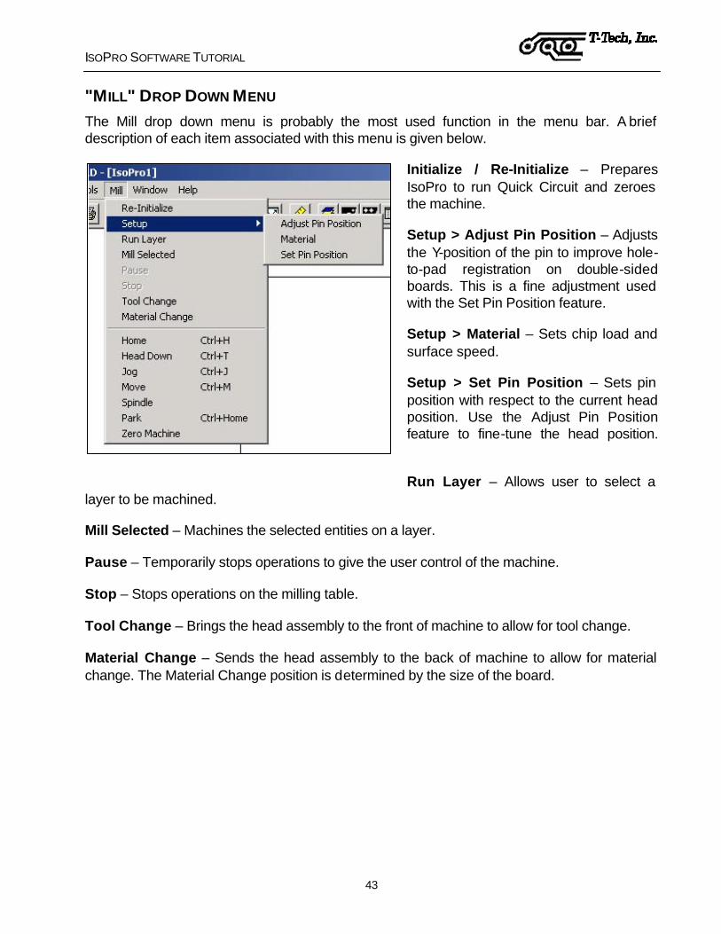
"MILL" DROP DOWN MENU The Mill drop down menu is probably the most used function in the menu bar. A brief description of each item associated with this menu is given below.
Initialize / Re-Initialize – Prepares IsoPro to run Quick Circuit and zeroes the machine.
Setup > Adjust Pin Position – Adjusts the Y-position of the pin to improve hole-to-pad registration on double-sided boards. This is a fine adjustment used with the Set Pin Position feature.
Setup > Material – Sets chip load and surface speed.
Setup > Set Pin Position – Sets pin position with respect to the current head position. Use the Adjust Pin Position feature to fine-tune the head position.
Run Layer – Allows user to select a layer to be machined.
Mill Selected – Machines the selected entities on a layer.
Pause – Temporarily stops operations to give the user control of the machine.
Stop – Stops operations on the milling table.
Tool Change – Brings the head assembly to the front of machine to allow for tool change.
Material Change – Sends the head assembly to the back of machine to allow for material change. The Material Change position is determined by the size of the board.

ISOPRO SOFTWARE TUTORIAL
44
Home – Returns the head assembly to Home position. (Home is specified under Preferences > Machine Settings in the menu bar.)
Head Down/Up – Raises or lowers the head assembly.
Jog – Places the machine under user control.
Move – Allows an absolute or relative move of the head assembly.
Spindle – Turns the spindle on or off. A checkmark next to this item indicates that the spindle is on.
Park – Returns the head assembly to the Park position. (The Park position is set under Preferences > Machine Settings in the menu bar. The head assembly travels to the designated Park position after completing a drill/mill routine.)
Zero Machine – Zeroes the milling table.
RIGHT-CLICK MENU Right clicking in the main window and selecting the “Machine” cursor menu gives you the
following display.
Jump to Cursor – Moves the head assembly to the current X,Y position of the cursor.
Machine Net – After right clicking on an entity, the machine mills all entities contained in connected the net.
Test Depth of Cut – Allows you to test the depth of cut of a pointed milling tool. This feature is not available if the machine has not been initialized.
Mill to End – If you need to stop machining on a board before the entire layer is finished, this feature allows to specify a new starting point and select Mill to End to finish machining the layer entities.

ISOPRO SOFTWARE TUTORIAL
45
MANUAL CONFIGURATION OF ISOPRO MACHINE DRIVE When you install IsoPro using the CD/disks included with your machine, your machine configuration is set automatically. However, if you need to set or change some of these parameters, you can do so by selecting Edit > Preferences > Machine Settings tabs.
Machine Model – Allows to select your machine type, QC model 5000 or 7000.
Comm Port – Allows you to specify which communications port the AMC2500 controller is connected to
High Speed Spindle – Allows you to indicate whether or not you are using a high-speed spindle.
Feeds (inches per minute)
Milling Speed – Indicates the tool speed with the head assembly down during a manual move.
Traverse Speed – Indicates the speed at which a tool moves with the head assembly up.

ISOPRO SOFTWARE TUTORIAL
46
Bed Size (inches)
X- – Indicates the usable bed space in front of the pinning hole. This area is used to prepare mill paths before machining.
X+ – Indicates the usable bed space behind the pinning hole.
Y- – Indicates the usable bed space to the right of the pinning hole.
Y+ – Indicates the usable bed space to the left of the pinning hole.
Home Offset from Pin (inches) The Home position is usually set at X = 0, Y = 0.
X distance – Determines the location of the Home position on the X-axis as an offset value from pinning position.
Y distance – Determines the location of the Home position on the Y-axis as an offset value from pinning position.
Spindle Speed (RPM)
Min – Indicates the minimum actual speed to be associated with the minimum software speed. This value will be different if you use a high-speed spindle.
Max – Indicates the maximum actual speed to be associated with the maximum software speed. This value will be different if you use a high-speed spindle.
Park Position (inches) The Park position should outside the edges of the board. After each layer is machined, the head assembly moves to the Park position.
X location – Determines the location of the Park position on the X-axis as offset from the Home position.
Y location – Determines the location of the Park position on the Y-axis as an offset from the Home position
Z-Axis
Solenoid – Indicates that a solenoid is used to move the head assembly up/down.
Air Cylinder – Indicates that an air cylinder is used to move the head assembly up/down.

ISOPRO SOFTWARE TUTORIAL
47
Z-Axis Ramp Time (sec)
Milling – Indicates the time it takes to ramp the solenoid power from zero to full power while milling.
Drilling – Indicates the time it takes to ramp the solenoid power from zero to full power while drilling.
Solenoid PWM Frequency – Base frequency that is used by the pulse width modulation of the solenoid. There should not be any reason for you to change this value.
Z-Axis Delay (sec)
Separate Delay for Drilling and Milling operations.
Up – Indicates the amount of time to wait after a head up command before continuing with next command.
Down – Indicates the amount of time to wait after a head down command before continuing with next command.
Z-Axis Ramp Time, Solenoid PWM Frequency and Z-Axis Delay should not be changed from their defaults unless you are experiencing problems with tools not penetrating your board material or dwelling too long in the board material.
ADDITIONAL FEATURES There are many additional features built into the IsoPro program. You should take the time to become thoroughly familiar with all of the tasks, icons and commands. Please reference IsoPro’s extensive on line Help menu for additional information concerning IsoPro’s features.

QC SYSTEM OPERATIONS
48
QUICK CIRCUIT SYSTEM OPERATIONS
The first time you use the Quick Circuit system, you will need to check the system out and become aware of a few facts concerning the use of the machine. Once you are familiar with IsoPro and the Quick Circuit machining operations, you will only need to refer to the following diagram to make sure that you have set everything up correctly.
Verify equipment
connections Pin the board
No
Yes
Buff board
Open ISO file: initialize table
Drill another layer?
Load tool; adjust height
& depth of cut
Drill first layer
Mill first isolation layer
Load new tool; adjust
height & depth of cut
Route the board outline
Is this a two-sided
board?
Mill another layer
(isolation or text)?
Load tool; adjust height
& depth of cutLoad new
drill bit
Remove board
Load tool; adjust height
& depth of cut
Flip the board
No
Yes
No
Yes
Figure 8 - Quick Circuit System Operations Diagram
See page 59 or 60
See page 45
See page 61
See page 64
See pages 54 - 57
See page 58
See page 52
See page 48
See page 66 to mill text
See page 45
See page 67
See page 66
See page 67
QC SYSTEM OPERATIONS
49
The Operations diagram refers you to certain pages in the manual where you can find detailed information concerning each task. Refer to these pages as often as needed until you have a thorough understanding of the Quick Circuit system.
Important: Always wear safety glasses when operating the Quick Circuit System.
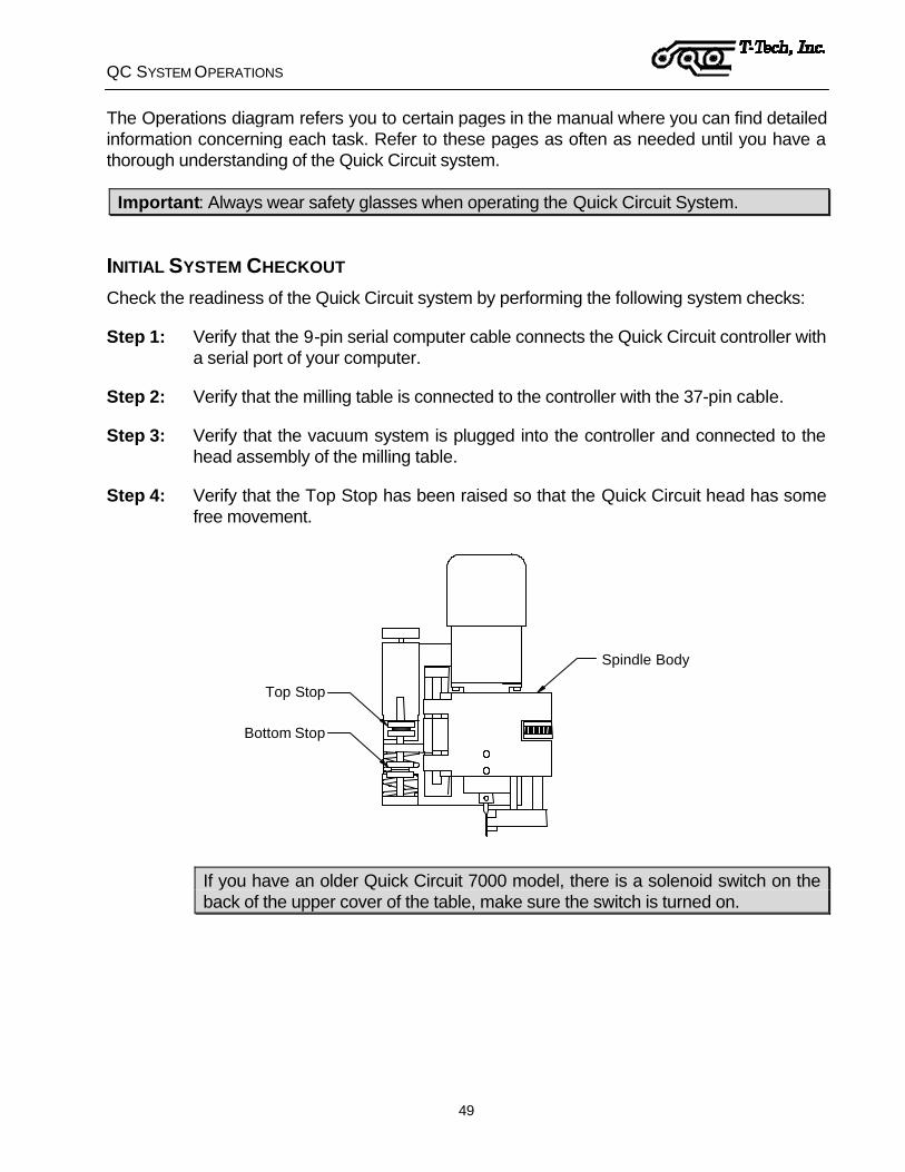
INITIAL SYSTEM CHECKOUT Check the readiness of the Quick Circuit system by performing the following system checks:
Step 1: Verify that the 9-pin serial computer cable connects the Quick Circuit controller with a serial port of your computer.
Step 2: Verify that the milling table is connected to the controller with the 37-pin cable.
Step 3: Verify that the vacuum system is plugged into the controller and connected to the head assembly of the milling table.
Step 4: Verify that the Top Stop has been raised so that the Quick Circuit head has some free movement.
Spindle Body
Top Stop
Bottom Stop
If you have an older Quick Circuit 7000 model, there is a solenoid switch on the back of the upper cover of the table, make sure the switch is turned on.
QC SYSTEM OPERATIONS
50
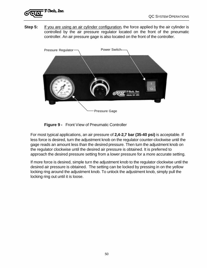
Step 5: If you are using an air cylinder configuration, the force applied by the air cylinder is controlled by the air pressure regulator located on the front of the pneumatic controller. An air pressure gage is also located on the front of the controller.
Pressure Gage
Pressure Regulator Power Switch
Figure 9 - Front View of Pneumatic Controller
For most typical applications, an air pressure of 2,4-2,7 bar (35-40 psi) is acceptable. If less force is desired, turn the adjustment knob on the regulator counter-clockwise until the gage reads an amount less than the desired pressure. Then turn the adjustment knob on the regulator clockwise until the desired air pressure is obtained. It is preferred to approach the desired pressure setting from a lower pressure for a more accurate setting.
If more force is desired, simple turn the adjustment knob to the regulator clockwise until the desired air pressure is obtained. The setting can be locked by pressing in on the yellow locking ring around the adjustment knob. To unlock the adjustment knob, simply pull the locking ring out until it is loose.

QC SYSTEM OPERATIONS
51
Step 6: If you are using a air cylinder configuration, the speed at which the air cylinder activates is controlled by the speed controller located on top of the air cylinder.
The speed is increased by turning the adjustment knob counterclockwise. Similarly, the speed is decreased by turning the adjustment knob clockwise. The speed should be set at a point where the smallest tools that you typically work with will not break due to the air cylinder activating too fast.
This setting is typically acceptable for a broad range of applications. However, you may find it necessary to occasionally adjust it depending on your application. Also, the speed controller setting varies with the air pressure. This means that if you change your air pressure, you may need to readjust your speed controller.
Step 7: Turn on the controller, then turn on your computer.
Step 8: Double-click on the IsoPro icon on your desktop.
Step 9: Initialize the milling table by selecting Mill > Initialize from the menu bar.
If prompted, specify your Quick Circuit machine model and type of spindle you are using. If you are importing files from QuickCam, specify the location of your “cam.ini” configuration file.
If you have a "cam.ini" file available, press “Yes” and choose the directory where the file is located. If you do not have a "cam.ini" file, select “No” and configure your machine settings manually as described on page 44.
The milling table will zero itself by moving to the front right edge of the milling table to determine its limits, then moving to the Park position.
Step 10: Go to the Tool change position by selecting Mill > Tool Change from the menu bar and then select OK when prompted.

QC SYSTEM OPERATIONS
52
Step 11: Check the operation of the head assembly by toggling its position manually. Select Mill > Head Up/Down from the menu bar.
Step 12: Check the operation of the spindle by turning it on and off throught the Mill > Spindle command in the menu bar. The vacuum system and spindle should turn on and off at the same time. A checkmark indicates when the spindle is on.
Step 13: Return the head assembly to the Home position by selecting Mill > Home or pressing Ctrl+H.
PINNING A BOARD The quality of your final circuit board is limited by the precision used in creating your pinning holes. For example, if there is a 0,05 mm (0.002”) play in your pinning holes, then the boards position while drilling and milling the component side will be 0,05 mm (0.002”). In addition when you flip your board over to mill and drill your solder side, positioning will also vary by 0,05 mm (0.002”). This results in a total variance in position of 0,10 mm (0.004”).
It is of the utmost importance to create pinning holes as precisely as possible.
Drilling Through-Holes using a Drill Press
In order to drill the through-holes in your circuit board without damaging the table and breaking carbide bits, a piece of backup material is used underneath the circuit board material. This backup material may be used a few times before flipping it over to the other side. After making a few boards on each side, the backup material will have to be replaced.
In order to maintain accuracy, the backup material is pinned to the circuit board material. The backup material should cover and protect the entire area beneath the circuit board material. If at all possible, use a drill press to drill the holes for the dowel pins.
QC SYSTEM OPERATIONS
53
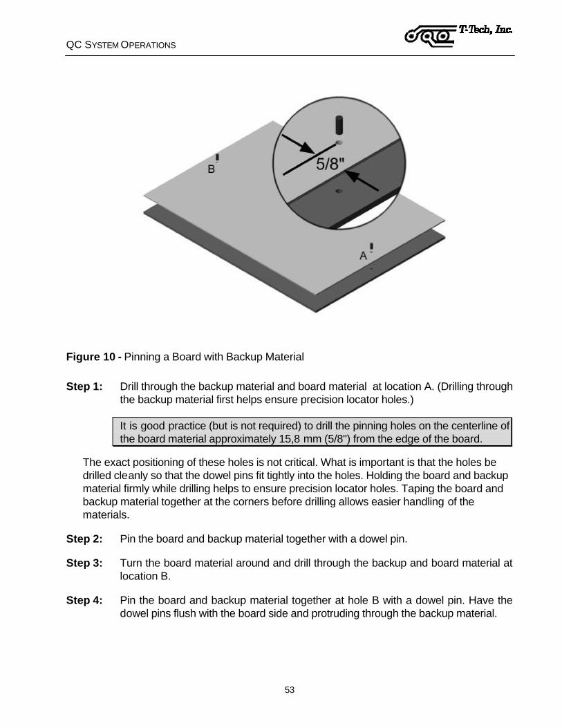
Figure 10 - Pinning a Board with Backup Material
Step 1: Drill through the backup material and board material at location A. (Drilling through the backup material first helps ensure precision locator holes.)
It is good practice (but is not required) to drill the pinning holes on the centerline of the board material approximately 15,8 mm (5/8") from the edge of the board.
The exact positioning of these holes is not critical. What is important is that the holes be drilled cleanly so that the dowel pins fit tightly into the holes. Holding the board and backup material firmly while drilling helps to ensure precision locator holes. Taping the board and backup material together at the corners before drilling allows easier handling of the materials.
Step 2: Pin the board and backup material together with a dowel pin.
Step 3: Turn the board material around and drill through the backup and board material at location B.
Step 4: Pin the board and backup material together at hole B with a dowel pin. Have the dowel pins flush with the board side and protruding through the backup material.

QC SYSTEM OPERATIONS
54
Drilling Through-Holes using Quick Circuit
If you do not have a drill press, it is also possible to use the Quick Circuit machine to drill the pin holes. Some Quick Circuit machines have a drilling clearance hole at a distance of 8 mm (0.312”). from the primary pinning hole, as well as a scale along the leading edge of the table.
Drilling clearance hole
Primary pinning hole
Figure 11 - Milling Table Scale and Drilling Hole
If your Quick Circuit table does not have a scale and clearance hole similar to the one shown here, call Technical Support for information on how to drill dowel pin holes for your model Quick Circuit.
Warning: The following instructions apply only to Quick Circuit models equipped with a drilling clearance hole. Use of these instructions on inappropriate Quick Circuit models will damage the Quick Circuit table top.
Step 1: Double-click on the IsoPro icon on your desktop.
Step 2: The drilling clearance hole is located at the absolute 0,0 position on the milling table. This should be verified in order to prevent accidental drilling into the table top.
Select Mill > Move from the menu bar or pressing Ctrl+M, then move the head assembly to absolute zero in both the X- and Y-axis. The spindle assembly's chuck should center itself above the drilling clearance hole.
Step 3: Go to the Tool Change position by selecting Mill > Tool Change from the menu bar.
Step 4: Loosen the chuck's set screw and place an 3,2 mm (1/8”) in the chuck so that the tip of the bit is just above the board material. Tighten the chuck's set screw.

QC SYSTEM OPERATIONS
55
Step 5: Move the head assembly back to the absolute 0,0 position.
Select Mill > Move from the menu bar or pressing Ctrl+M, then move the head assembly to absolute zero in both the X- and Y-axis. The spindle assembly's chuck should center itself above the drilling clearance hole.
Step 6: While the chuck is centered above the drilling clearance hole, place the board and backup material on the table in the correct position to drill pin hole A. (Drilling through the backup material first helps ensure precision locator holes.)
It is good practice (but is not required) to drill the pinning holes on the centerline of the board material approximately 15,8 mm (5/8") from the edge of the board.
The exact positioning of the holes in the board is not critical. What is important is that the holes be drilled cleanly so that the dowel pins fit tightly into the holes. Holding the board and backup material firmly while drilling helps to ensure precision locator holes. Taping the board and backup material together at the corners before drilling allows easier handling of the materials.
Step 7: Use the Spindle On/Off and Head Up/Down commands to drill the pin hole (select Mill > Spindle, then Mill > Head Up/Down from the menu bar).
Step 8: Use the Mill > Move command or Ctrl+M to move the head assembly away from the board.
Step 9: Pin the board and backup material together with a dowel pin.
Step 10: Turn the board material around and repeat steps 5-9 to drill through the backup and board material at location B.
Placing a Board on the Milling Table
When you are ready to start making a board, place the pinned board and backup material on the milling table with one of the extended dowel pins in the primary pinning hole and the second pin in the groove that runs down the middle of the milling table. Have the board material facing up.
Secure the left and right edges of the board and backup material down with masking tape. This adds to the stability and accuracy of the system.
Caution: Avoid scratching the table with the pins. Avoid hitting the vacuum nozzle with the board material.
If you are creating a double-sided board, when the time comes, remove the tape, carefully pull the circuit board material off of the dowel pins, flip the material (left to right), and place it back on the same pins with the other side of the board facing up.

QC SYSTEM OPERATIONS
56
PREPARING YOUR *.ISO FILE Step 1: Open IsoPro by double clicking on the icon on your desktop.
Step 2: Open the *.iso file you want to mill.
Step 3: Verify aperture list by clicking on the Aperture Table icon , selecting View > Aperture Table or pressing F3.
If you do not have an aperture list loaded, you will notice that your aperture dimensions default to 9.99 and 49.99. This is a very distinctive size and will probably never be used on a circuit board. If you see these values in your list, manually edit the aperture widths to match the output of your CAD package.
Step 4: Verify tool table by clicking on the Tool Table icon , selecting View > Tool Table or pressing F4.
The tool table usually imports into IsoPro automatically, but on occasion it may not. In that case you must edit the data manually. If your tool sizes default to 49.99, this is a flag that indicates these are the default values. Manually edit the Tool Table to match your tool sizes.
QC SYSTEM OPERATIONS
57
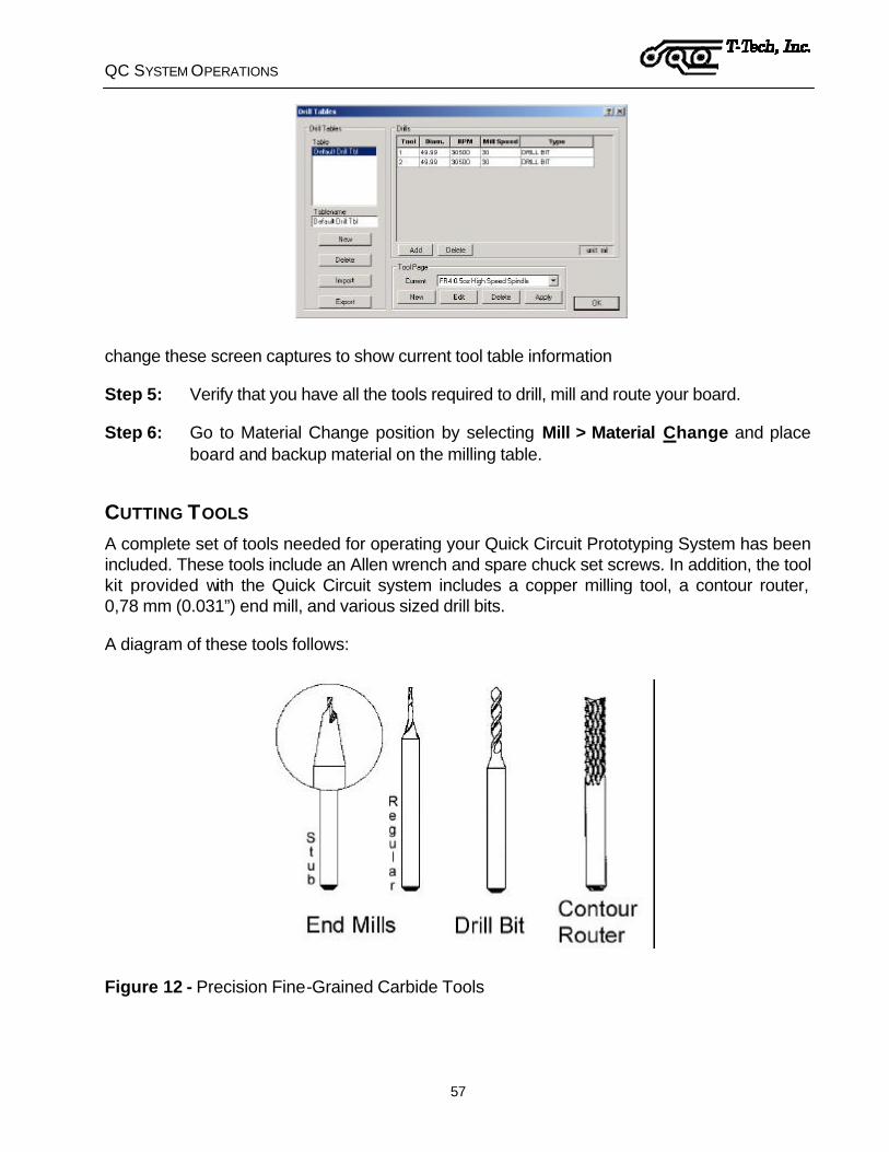
change these screen captures to show current tool table information
Step 5: Verify that you have all the tools required to drill, mill and route your board.
Step 6: Go to Material Change position by selecting Mill > Material Change and place board and backup material on the milling table.
CUTTING TOOLS A complete set of tools needed for operating your Quick Circuit Prototyping System has been included. These tools include an Allen wrench and spare chuck set screws. In addition, the tool kit provided with the Quick Circuit system includes a copper milling tool, a contour router, 0,78 mm (0.031”) end mill, and various sized drill bits.
A diagram of these tools follows:
Figure 12 - Precision Fine-Grained Carbide Tools

QC SYSTEM OPERATIONS
58
The drill bits are industry standard 38 mm (1.5”) long, 3,2 mm (1/8”) diameter shank circuit board drills. These drills are available in any number size from 31 to 70, any metric size from 0,75 to 3,15 mm and fractional sizes up to 1/8”.
The end mills are used to mill large paths in the board material. This is useful in wide path milling or copper rubout. The width of cut of an end mill is simply the size of the end mill.
The copper milling tools are custom made for the purpose of milling copper circuit board material. The copper milling tool has a pointed tip. The tool depth determines the width of cut.
The contour routers are used to route a board outline from a piece of board material or to perform interior routing.
ADJUSTING THE HEAD ASSEMBLY
Pressure Foot
Top Stop
Bottom Stop
Setting the Upper Travel Limit
A pair of thumb nuts is provided to set the Top Stop position. The lower nut will set the location; the upper nut will lock the nuts in position.
The Top Stop setting will also allow the operator to limit the amount of upward travel of the solenoid plunger. Insufficient solenoid force to start motion will result from too large solenoid top extension, e.g. greater than 5 mm (0.200”).
Check the upper travel limit to be sure that a cutting tool will pass above the table and board material before allowing the head to move.

QC SYSTEM OPERATIONS
59
Setting the Lower Travel Limit
Most of the time the pressure foot will be used to control the depth of cut of a tool. If you do not use the pressure foot, you can set the lower travel limit of the head assembly by setting the Bottom Stop thumb nuts. The upper nut will set the location; the lower nut will lock the nuts in place.
When you do use the pressure foot, move the Bottom Stop to the extreme down locked position to avoid restricting the downward movement of the head assembly.
Setting the Vacuum Inlet Tube
The vacuum tube can be positioned for various work heights. Release the thumb screw on the tube clamp to slide and rotate the tube as needed. Place the inlet close to the interface of the cutting tool and the work surface.
The tube must be placed high enough to pass above the table and board material. It must not touch the pressure foot or the head assembly, since this could restrict vertical motion.
Setting the Air Cylinder Force
The force applied by the air cylinder is controlled by the air pressure regulator located on the front of the pneumatic controller. An air pressure gage is also located on the front of the pneumatic controller.
For most typical applications, an air pressure of 2,4-2,7 bar (35-40 psi) is acceptable. If less force is desired, turn the adjustment knob on the regulator counterclockwise until the gage reads an amount less than the desired pressure. Then turn the adjustment knob on the regulator clockwise until the desired air pressure is obtained. It is preferable to approach the desired pressure setting from a lower pressure for a more accurate setting.
If more force is desired, simple turn the adjustment knob to the regulator clockwise until the desired air pressure is obtained. The setting can be locked by pressing in on the yellow locking ring around the adjustment knob. To unlock the adjustment knob, simply pull the locking ring out until it is loose.
Setting Speed on a the High-Speed Spindle
The IsoPro software controls the spindle power converter for spindle speed. The upper and lower limits for the spindle speed are set automatically according to the Tool table.
The high speed spindle motor must be allowed to come to a complete stop before resuming milling. After a stop, the converter speed display should return to zero and the yellow speed change and operational green light should go off in order to indicate that the external converter is ready for the next command.

QC SYSTEM OPERATIONS
60
SETTING TOOL HEIGHT The procedure to set the height of a tool above your circuit board will be the same regardless of the type of tool or spindle assembly used.
Circuit Board
Milling Table
Backup Material
Drill Motor
Spindle Body
Knurl Nut
Pressure Foot
BottomStop
Top Stop
Solenoid Knob
Figure 13 - Setting the Tool Height Above a Circuit Board
Step 1: Select Mill > Jog from the menu bar or Ctrl+J and position the drill bit to the side of the board.
Step 2: Using the Top Stop thumb nuts, position the bottom of the tool just slightly above the circuit board material.
By keeping the tool as close as practical to the board material, you will greatly increase tool life and accuracy. This is due to the velocity with which the tool hits the board material when using a solenoid configuration. The higher the tool starts above the material, the greater the solenoid will accelerate the tool before entry into the board material.
This acceleration increases the chance of the carbide tool chipping or breaking. A good rule is to place the 1,6 mm (1/16") Allen wrench flat on the board material next to the bit. Then adjust the Top Stop to have the tool's height above the board material to be less than the thickness of the Allen wrench.

QC SYSTEM OPERATIONS
61
SETTING DEPTH OF CUT FOR DRILLING
Always set the tool height above the circuit board BEFORE setting the depth of cut.
After loading the correct drill, set your depth of cut. When drilling you want the bit to drill completely through the circuit board material and slightly into the backup material.
BoardMaterial
Drill Bit
BackupMaterial
Pressure Foot
Table Top
Figure 14 - Setting the Depth of Cut of Drill Bit (magnified view of head assembly and pressure foot)
To the right side of the spindle body is the Knurl nut (nut with ridges). Below this nut, is the pressure foot. The pressure foot rides along the surface of the material on the milling table. This allows you to set the tool depth of cut accurately with regards to the material's surface. Otherwise slight warps in the material would influence your depth of cut.
Turning the ridges on the knurl nut to the left as you face the head (or clockwise if you are looking down on it) will raise the pressure foot thereby increasing your depth of cut. The Knurl Nut has clicks or detents in it. Each detent moves the pressure foot up or down by 0,010 mm (0.0004") increments.
Step 1: Press down on the head assembly.
Step 2: Rotate the Knurl Nut until the point of the drill bit is below the bottom of the circuit board material when the pressure foot is flush against the board material.

QC SYSTEM OPERATIONS
62
Setting the Solenoid Force
The solenoid has a limited stroke with force. Be sure to have the solenoid plunger positioned to have a gap between the e-ring and the case in order to keep from restricting downward motion.
When changing the range of motion of the head assembly, change the solenoid adjustment to match this range using the Solenoid Knob. Failure to do this may restrict the vertical motion.
DRILLING YOUR BOARD
Note: Drill the holes in your board before you mill the traces. Drilling a hole in the center of a small annular ring might cause the copper cladding to come loose from the base material.
Note: Improved registration accuracy of small diameter drill holes can be achieved by using Entry Material. T-Tech stocks high quality entry material for this purpose.
Sometimes it is necessary to drill only part of a layer. Depending on your file you can use one of the following methods:
1) Select all entities that you would like to drill. Click on Mill > Mill Selected from the menu bar.
2) Right-click on the entity you want to drill, and select Machine > Machine Net under the cursor menu.
To drill an entire layer, follow these steps:
Step 1: In the Layer palette on the left side of your screen, right click on the first drill layer you want to machine.
Step 2: Select Run Layer. The milling table automatically goes to the Tool Change position.
Step 3: Install the required drill bit and adjust your tool height and depth of cut, as needed. Refer to Adjusting the Head Assembly and Setting Depth of Cut for Drilling starting on page 61.
Step 4: Adjust the position of the vacuum tube, as needed. Refer to Setting the Vacuum Inlet Tube on page 59.

QC SYSTEM OPERATIONS
63
Step 5: When ready, select Run on your screen. The milling table drills all the holes specified on the layer.
Since there is no way for the machine to know whether or not you are finished with this board, the head assembly moves to the Park position outside the edges of the board when it has completed each layer.
If you have another drill layer to machine, select the desired layer from the Layer Palette and click on Run Layer. The milling table automatically moves to the Tool Change position to allow you to insert the proper tool. Drill bits come in one standard length of 38 mm (1.5”). Unless your tool is very worn, there should be no need to adjust the tool height and depth of cut. Solenoid force adjustment may be necessary for optimum performance.
If your next operation is milling an isolation path, manually move the head assembly to the Tool Change position. When changing tools from a drill bit to a milling tool, you will need to set the tool height and depth of cut as described on pages 59 and 63 respectively.
CHANGING A TOOL ON A STANDARD SPINDLE
Note: There are important differences in the operation of the Quick Circuit when using the optional high-speed spindle. The high-speed spindle requires a different procedure for tool changing. See page 64.
For this procedure, you will need the 1,6 mm (1/16") Allen wrench and the drill bit or milling tool you plan to use.
Step 1: Move the head assembly to the Tool Change position by selecting Mill > Tool Change from the menu bar.
Step 2: Using the 1,6 mm (1/16") Allen wrench loosen the set screw on the chuck.
The tool should then fall out of the chuck. Caution is advised as these tools are delicate and can be easily damaged through mishandling.
Step 3: Store the removed tool in its correct place.
Step 4: Then place the new tool bit in the chuck insuring that the tool is seated completely up in the chuck. While holding the bit in place, tighten the set screw with the Allen wrench. The tool can be held in place comfortably with your fingernail or optionally you may wish to purchase the Tool Grip from T-Tech.
Step 5: Adjust the tool height and depth of cut for the current operation (drilling, milling, routing). Refer to the appropriate setting instructions.

QC SYSTEM OPERATIONS
64
CHANGING A TOOL ON A HIGH-SPEED SPINDLE This motor spindle has a tool chuck that uses a collet. A collet is a tapered sleeve that evenly squeezes the tool. Turning the knob at the top of the motor spindle unit operates the collet. The collet must be loose, or open, to accept a cutting tool. The collet should be tightened only when a tool has been inserted.
Step 1: Move to the Tool Change position.
Step 2: Press down on the knob. Turning the knob slightly while pressing will allow the knob to go fully downward and lock the rotation of the spindle. The knob can loosen and tighten the collet only when the knob is fully down with the spindle rotation locked.
Never press the knob down while the spindle is rotating!
You may find it convenient to hold the head down with your left thumb on the pressure foot. The left hand fingers can hold the tool in place while turning the knob with the right hand.
Step 3: Loosen the collet by turning it counterclockwise.
Step 4: Install the desired tool bit.
Step 5: Tighten the collet by turning it clockwise. The knob is small because firm finger tightness is all that is required for securing a tool shank in the collet.
Caution: Over-tightening will increase runnout and if extreme could damage the collet. Contour routing is the only operation that will need to have the tool firmly tightened. Refer to the motor manufacturer's literature.

QC SYSTEM OPERATIONS
65
ADJUSTING DEPTH OF CUT FOR MILLING You can perform your milling operations using a fixed diameter end mill or a pointed milling tool. The pointed milling tool allows you to machine the board at greater speeds, but requires a more complicated depth of cut adjustment.
With an end mill, the width of the milling path is approximately equal to the diameter of the end mill. To adjust the depth of cut, follow the instructions below. For a pointed milling tool, the width of the path depends on the depth of cut of the tool. See the following pages for details on setting the depth of cut of both the end mill and the pointed milling tool.
Setting End Mill Depth of Cut
Always set the tool height above the circuit board BEFORE setting the depth of cut.
To the right side of the spindle body is a nut with ridges, called the Knurl Nut. Below the nut, is the pressure foot. The pressure foot rides along the surface of the material on the milling table. This allows you to set the tool depth of cut accurately with regards to the material's surface. Otherwise slight warps in the material would influence your depth of cut.
Step 1: Move the spindle to the front of the board and left or right from the positioning pin. These areas are not usually used on the board. Select Mill > Move or press Ctrl+M, then manually jog the machine to the desired position.
Step 2: Press down on the head assembly.
Step 3: Rotate the knurl nut until the bottom of the end mill is flush with the circuit board material when the pressure foot is down.
Turning the ridges on the knurl nut to the left as you face the head (or clockwise if you are looking down on it) will raise the pressure foot thereby increasing your depth of cut.
Step 4: Adjust the depth of cut for the layer you are going to mill.
The knurl nut has clicks or detents in it. Each detent moves the pressure foot up or down by 0,010 mm (0.0004") increments. The following recommended settings are intended to be used as a starting point; individual applications will vary.
Recommended settings:
14 g (½ oz.) copper
3 clicks positive
28 g (1 oz.) copper
5 clicks positive
56 g (2 oz.) copper
9 clicks positive
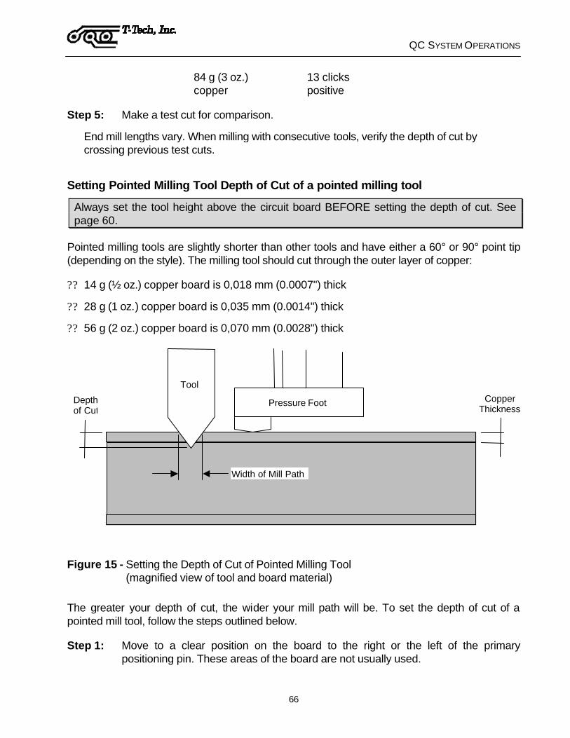
QC SYSTEM OPERATIONS
66
84 g (3 oz.) copper
13 clicks positive
Step 5: Make a test cut for comparison.
End mill lengths vary. When milling with consecutive tools, verify the depth of cut by crossing previous test cuts.
Setting Pointed Milling Tool Depth of Cut of a pointed milling tool
Always set the tool height above the circuit board BEFORE setting the depth of cut. See page 60.
Pointed milling tools are slightly shorter than other tools and have either a 60° or 90° point tip (depending on the style). The milling tool should cut through the outer layer of copper:
?? 14 g (½ oz.) copper board is 0,018 mm (0.0007") thick
?? 28 g (1 oz.) copper board is 0,035 mm (0.0014") thick
?? 56 g (2 oz.) copper board is 0,070 mm (0.0028") thick
Copper Thickness
Pressure Foot
Width of Mill Path
Depth of Cut
Tool
Figure 15 - Setting the Depth of Cut of Pointed Milling Tool (magnified view of tool and board material)
The greater your depth of cut, the wider your mill path will be. To set the depth of cut of a pointed mill tool, follow the steps outlined below.
Step 1: Move to a clear position on the board to the right or the left of the primary positioning pin. These areas of the board are not usually used.

QC SYSTEM OPERATIONS
67
Step 2: Test the width of your mill path by right-clicking on the area of the board where you want to perform the test and selecting Machine > Test Depth of Cut from the pop-up menu. Select the desired width and press OK.
The milling table will machine a horizontal path; move up by the width of the milling path, then turn back and machine a path parallel to the first one.
Step 3: Inspect the results. If the two paths do not touch, the tool is not cutting deep enough into the copper. If the two paths overlap, the depth of cut is too big. To be exact, the two paths must just touch as illustrated below.
The two cut pathsdo not touch
The two cut pathsjust touch
The two cut pathsoverlap
Figure 16 - Inspecting Mill Paths
If the depth of cut needs adjustment, jog it some more with one hand on the keyboard and adjust the knurl nut with the other. Remember the deeper a tapered, pointed milling tool mills into the board material the wider the cut path. When you have a satisfactory depth of cut, lift the head and turn off the drill motor.
Once you have gained some experience, you may prefer to adjust the depth of cut while you mill the file. Start with the tip of the milling tool above the board material and adjust it downward while running the file. When the depth of cut is properly set, stop the milling process and restart the mill file. Quick Circuit's accuracy ensures that the original mill path will be precisely re-milled.

QC SYSTEM OPERATIONS
68
MILLING YOUR BOARD To mill an entire layer, follow these steps:
Step 1: In the Layer palette on the left side of your screen, right click on the first isolation layer you want to machine.
Step 2: Select Run Layer. The milling table automatically goes to the Tool Change position.
Step 3: Install the required milling tool and adjust your tool height and depth of cut. Refer to the Setting Tool Height and Adjusting Depth of Cut for Milling sections in this manual.
Step 4: Adjust the position of the vacuum tube as needed.
Step 5: When ready, press OK in the Tool Change dialog box. The machine mills the isolation paths from the selected layer.
When the selected layer is finished, the head assembly moves to its Park position outside the edges of the board when it has completed each phase.
Step 6: Repeat steps 2-6 for each isolation or rub out layer.
For each Isolation or rubout layer, there is a tool diameter appended by IsoPro the end of the layer name. For example:
?? 274x.gbr (31.0 mils)
?? 274x.gbr (31.0 mils rub out)
?? 274x.gbr (10.0 mils)
?? 274x.sol (31.0 mils)
?? 274x.sol (10.0 mils)
Complete the component side before proceeding to the solder side since this requires flipping the board material, and run the smallest tool first. In the example above, you would run the 274x.gbr (10 mils) layer first, then the 31.0 mils layer, then the rub out layer for the 31.0 mils tool.

QC SYSTEM OPERATIONS
69
Sometimes it is necessary to mill only part of a layer. Depending on your file you can use one of the following methods:
1) Select all entities that you would like to mill. Click on Mill > Mill Selected from the menu bar. This will mil only the entities selected.
2) Right-click on an entity on the net that you want to mill, and select Machine > Machine Net under the cursor menu. This will mill all the entities connected to the entity selected.
3) Right-click on the entity you want to continue from and select Machine > Mill to End…. This will continue the milling file from the entity selected to the end of the file.
Milling Text and Symbols
Most CAD packages allow you to put text and symbols on your design. Quick Circuit can mill these.
Inspect your text layers. Problems arise when you take a Gerber file containing text and traces and isolate it using the IsoPro software. The IsoPro software will also isolate your text and symbols. Normally you do not want any symbols isolated. The isolated text will be the outline of what you originally entered.
Step 1: In the IsoPro software, copy your layer containing text to a second layer so that there are two identical layers.
Step 2: On one layer, delete everything that is not text and symbols.
Step 3: On the other layer, delete everything except text and symbols.
Step 4: Run the isolation routine on the layer that now has no text or symbols.
Step 5: Combine or Register the text and symbols layer to the isolated layer. This way, the Isolation routine will not take as long and you will probably prefer the results.
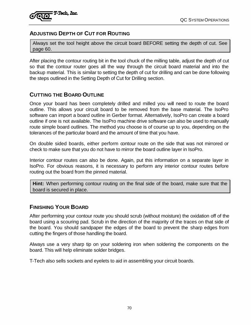
QC SYSTEM OPERATIONS
70
ADJUSTING DEPTH OF CUT FOR ROUTING
Always set the tool height above the circuit board BEFORE setting the depth of cut. See page 60.
After placing the contour routing bit in the tool chuck of the milling table, adjust the depth of cut so that the contour router goes all the way through the circuit board material and into the backup material. This is similar to setting the depth of cut for drilling and can be done following the steps outlined in the Setting Depth of Cut for Drilling section.
CUTTING THE BOARD OUTLINE Once your board has been completely drilled and milled you will need to route the board outline. This allows your circuit board to be removed from the base material. The IsoPro software can import a board outline in Gerber format. Alternatively, IsoPro can create a board outline if one is not available. The IsoPro machine drive software can also be used to manually route simple board outlines. The method you choose is of course up to you, depending on the tolerances of the particular board and the amount of time that you have.
On double sided boards, either perform contour route on the side that was not mirrored or check to make sure that you do not have to mirror the board outline layer in IsoPro.
Interior contour routes can also be done. Again, put this information on a separate layer in IsoPro. For obvious reasons, it is necessary to perform any interior contour routes before routing out the board from the pinned material.
Hint: When performing contour routing on the final side of the board, make sure that the board is secured in place.
FINISHING YOUR BOARD After performing your contour route you should scrub (without moisture) the oxidation off of the board using a scouring pad. Scrub in the direction of the majority of the traces on that side of the board. You should sandpaper the edges of the board to prevent the sharp edges from cutting the fingers of those handling the board.
Always use a very sharp tip on your soldering iron when soldering the components on the board. This will help eliminate solder bridges.
T-Tech also sells sockets and eyelets to aid in assembling your circuit boards.

TROUBLESHOOTING
71
TROUBLESHOOTING
The following is a list of possible solutions to common problems encountered with the Quick Circuit system:
The milling table does not respond
?? Is the milling table connected to the controller with the 37-pin cable?
?? Is the controller plugged in and turned on?
?? Does the power light of the controller come on when the controller is turned on?
?? Has the fuse in the back of the controller blown?
The head will not go up or down
?? Are the Top and Bottom Stops set approximately as described in the Adjusting the Head Assembly section?
?? Is the Vaccum tube touching the pressure foot?
?? Is the solenoid set approximately as described in the Adjusting the Head Assembly section?
The Quick Circuit machine generally runs poorly
?? Does your computer have a Pentium class or higher CPU and 32 megabytes or more of system memory?
?? Are there any other programs running at the same time as IsoPro or accessing the Quick Circuit's serial port?
TROUBLESHOOTING
72
Air Cylinder hesitates while drilling through or retracting from the material
?? The solenoid or air cylinder force is set too weak. Adjust the solenoid knob or increase the force of the air cylinder by turning the air regulator adjustment knob clockwise.
?? The Top Stop lock nuts are set too high. Lower the Top Stop position.
The drill holes seem to be randomly placed within the pads
?? The solenoid or air cylinder force is too great. Adjust the solenoid knob or decrease the force of the air cylinder by turning the air regulator adjustment knob counterclockwise.
?? The random drilling is known as “drill wander” and is most common in smaller holes. Using adhesive entry material or new drill bits will also help with this problem.
?? The Top Stop lock nuts are set too high. Lower the Top Stop position.
Drills bits break often or wear quickly
?? The solenoid or air cylinder force is too great. Adjust the solenoid knob or decrease the force of the air cylinder by turning the air regulator adjustment knob counterclockwise.
?? The Top Stop lock nuts are set too high. Lower the Top Stop position.
There is a wide point in the milling path when using a pointed milling tool
?? The solenoid or air cylinder force is too great. Adjust the solenoid knob or decrease the force of the air cylinder by turning the air regulator adjustment knob counterclockwise.
?? The Top Stop lock nuts are set too high. Lower the Top Stop position.

TROUBLESHOOTING
73
The width of the cut varies from one edge of the path to the other when using a pointed milling tool
?? The solenoid or air cylinder force is too great. Adjust the solenoid knob or decrease the force of the air cylinder by turning the air regulator adjustment knob counterclockwise.
?? The machine may be out of alignment. Contact T-Tech Service Department.
The pads are low in relation to the drill holes
?? The solenoid is incorrectly set. If the solenoid knob is set too high, the solenoid force will be too weak. If the solenoid knob is set too low, the solenoid will bottom out. Adjust the solenoid knob as needed.
?? The air cylinder force is too weak. Increase the force of the air cylinder by turning the air regulator adjustment knob clockwise.
The tool does not contact the copper when the head starts moving when using a pointed milling tool
?? The air cylinder force is too weak. Increase the force of the air cylinder by turning the air regulator adjustment knob clockwise.
?? The Top Stop lock nuts are set too high. Lower the Top Stop position.
?? The Bottom Stop lock nuts are set too high. Lower the Bottom Stop position.
?? The vaccum tube is touching the pressure foot (stopping the Z motion).
??

TROUBLESHOOTING
74
DIAGNOSTICS If your Quick Circuit machine begins to produce low quality circuit boards, first, determine if the problem is hardware or software related. A file incorrectly exported from the IsoPro software will not be successfully machined. If Quick Circuit produces many different boards correctly except for one, then it is likely that the problem lies with the IsoPro file.
To discover if the problem lies with the Quick Circuit hardware, use the files included with the IsoPro software tutorial. These files are known to be correct. If the tutorial sample board is machined correctly, then the problem is not hardware related.
If the tutorial sample board is not machined correctly, then the problem is hardware related. Use this section to diagnose the problem.
?? Check the location of the Home position. It is possible that your Home Position needs adjustment.
If you experience repeatable offsets on multiple boards then it is likely that your home position needs adjusting. A need for home position adjustment is exhibited by all of the holes appearing to be offset approximately the same distance in the Y direction (left or right) when viewed from the bottom side. When performing the test make sure your board is pinned correctly with a precision locator hole (Refer to Section 3.5).
If you need further assistance, call T-Tech's technical support at (770) 455-0676.

TROUBLESHOOTING
75
SERVICE AND MAINTENANCE
Quick Circuit is a precision tool used to produce circuit boards. Proper care and routine maintenance are essential to ensuring optimal performance. This section describes the maintenance that you should routinely perform to maintain your system at peak operating performance.
SCHEDULE OF MAINTENANCE It is recommended that the Quick Circuit be kept clean of dust and chips generated by the manufacturing of circuit boards. This can easily be done by using the vacuum to remove any dust and chips that have accumulated on the machine surfaces. The vacuum hose can be used for cleaning by disassembling it from the vacuum tube by twisting the hose off the vacuum tube. Please pay special attention to the lead screws and linear ways. Make sure that the vacuum hose is properly reassembled to the vacuum tube before continuing with regular use.
Lead Screws
The lead screws are coated with black TFE to increase life and to provide smooth, quiet and accurate motion. Because of this the lead screws do not require lubrication of any kind. Any lubrication applied to TFE coated screws could cause the coating to wear prematurely. However, it is important that the lead screws be kept clean of dust and debris. This can be done by using the vacuum as described above to regularly clean the lead screws. Frequency of cleaning varies between users based on machine usage and application.
Linear bearings
Caution: When lubricating the Y-axis linear bearings, make sure that no lubricant drips onto the Y-axis lead screw. This will damage the TFE coating and void your warranty.
The linear bearings should be lubricated every 3 months to provide smooth, quiet motion of the machine and to prevent corrosion of important surfaces. More frequent lubrication may be required for you application. Proper lubrication is important since it ensures that excess friction in the bearings does not cause the machine to operate slower or stall. Use a lightweight oil such as 3-in-1 oil on the X, Y and Z-Axis linear bearings. The X-Axis linear bearings are mounted on both sides of the bottom surface of the table top. The Y-Axis linear bearing is mounted to the bottom of the cross support bar. The Z-Axis linear bearings are located to the left of the spindle. The linear bearings should be lubricated about every 4 weeks or as use warrants.
Note: 3-in-1 oil is the registered trademark of WD-40 Company, San Diego, CA.

TECHNICAL TIPS
76
TECHNICAL TIPS
This section addresses specific technical areas concerning the use of Quick Circuit that are not essential to its routine operation. Users may choose to read this section after becoming experienced with the operation of the Quick Circuit, and use it in reference to specific questions. Some of the information in this section was discovered or developed from our users in response to our request for input, tips, suggestions and techniques. Some information was discovered by T-Tech employees who thought the information may be useful to specific customer applications.
WIDE PATH MILLING Sometimes you will not have an end mill available with the same diameter as the diameter of the path you wish to mill. For instance suppose you require a 1,25 mm (0.050") mill path width but only have 0,25 mm (0.010"), 0,78 mm (0.031"), and 1,57 mm (0.062") end mills.
The solution is to have isolate a first path using the 0,78 mm (0.031") mill your first and offset the second path also using the 0,78 mm (0.031") mill. Overlapping the two paths results in a total mill path of the desired width.
Overlap
Width ofFirst Path
TRACE
Width ofSecond Path
Figure 17 - Overlapping Isolation Paths
When we are machining the layer, the total width of the mill path is equal to the sum of the widths of the first and second path minus the overlap value. In other words,
Total width = Width of first path + Width of second path - Overlap

TECHNICAL TIPS
77
The width of the first and second paths is equal to the diameter of the end mills used to trace the paths. By controlling the amount of overlap, you can modify the total width of the mill path.
However, IsoPro does not allow you to specify an offset to mill the second path. Therefore, we need to specify a tool diameter whose centerline will match the desired location of the second mill path.
It is important to know the basics of how the IsoPro isolates and outputs a layer. When IsoPro isolates an image group it outlines the pads and traces with an outline of specified thickness. This line is defined by a centerline, which is offset from the edge of the pad or traces by one half of the thickness of the outline. When the outline is drawn in IsoPro it is shown with the thickness of the tool diameter that was used when it was isolated. We will call this the IsoPro tool diameter.
By isolating a layer with a tool diameter larger than the actual diameter of the tool you plan to use to mill the second path, it is possible to offset the second path from the first. This prevents the first path from being totally overlapped when the layer is machined.
IsoProTool Diameter
Amount the secondpath was offset
Diameter of the endmill used to mill thesecond path
Centerlineof tool
Total width ofmachined mill path
Trace on Board
Figure 18 - Offsetting the Second Mill Path

TECHNICAL TIPS
78
Offsetting the Second Mill Path
The amount of offset of the second milling path is equal to the width of the first path minus the overlap.
Offset = Width of first path - Overlap
The amount of offset is also controlled by the available IsoPro tool diameter and the diameter of the tool used to mill the second path. By inspecting the diagram on the previous page, we see that:
Offset = (Tool diameter – Width of second path)/2
Combining the two expressions, we see that:
Offset = Width of first path – Overlap = (Tool diameter – Width of second path)/2
If we solve this equation in terms of the Overlap, we end up with:
Overlap = Width of first path - (Tool diameter – Width of second path)/2
Since we already know that the total width of the mill path will be the sum of the widths of the first and second paths minus the amount of overlap, we can solve this equation for the IsoPro tool diameter in terms of the diameters of the end mills you intend to use for your first and second paths and the total diameter you desire the mill path.
We know that
Total width = Width of first path + Width of second path – Overlap
and
Overlap = Width of first path - (Tool diameter – Width of second path)/2
Substituting in the Overlap, we get:
Total width = Width of first path + Width of second path – [Width of first path – (Tool diameter – Width of second path)/2]

TECHNICAL TIPS
79
Simplifying and solving for the Tool diameter, we end up with the offsetting equation:
Tool Diameter = 2 * Total width – Width of second path -- The offsetting equation
This is based on the assumption that the widths of the first and second paths are less than the total width. And obviously, the width of your first or second path can not be greater than the total width. It is also necessary to have some overlap between the first and second paths.
Using the offsetting equation, you should be able to achieve your desired total mill path with end mill(s) smaller than the total path. The equation is also valid if you use the same end mill for your first and second paths. An example of this follows.
Suppose you have a 0,78 mm (0.031") end mill and desire to mill a 0.050" mill path. You may choose to use the 0,78 mm (0.031") end mill for both your first and second paths. Therefore, we have:
Tool Diameter = 2 * Total width – Width of second path
Tool Diameter = 2 * 1,25 mm – 0,78 mm = 1,72 mm = 2 * 0.050 – 0.031 = 0.069"
Therefore, in IsoPro, we will specify the tool diameter for the first isolation path using the 0,78 mm (0.031") end mill and the second path using a (fake) 1,72 mm (0.069") tool. When we mill the board, however, we will use the same end mill for both layers. The 1,72 mm (0.069") tool diameter was used in the IsoPro software solely for the purpose of offsetting the centerline.
EXPORTING FILES TO FIT ON THE BOARD MATERIAL While viewing or editing files in the IsoPro, you will notice a large rectangle in the center of the screen. This rectangle shows approximately where the board material is relative to your files. Any part of your file that does not lie within this rectangle will not fit on your board material.
You may offset your layers so as to have them placed anywhere you desire on this board material. If a file is exported that has sections lying outside of the rectangle, the IsoPro software will issue an error message to this affect. IsoPro will not allow you to mill this file but you may view it.
Click on the Extents icon to view the entire extents of your drawing. If a file exceeds the work area, then the file must be offset in IsoPro so as to fit within the rectangle on the screen. By properly offsetting the layers of a file you should be able to produce circuit boards up to the size of the board material itself.

TECHNICAL TIPS
80
USE OF QUICK CIRCUIT FOR ENGRAVING While Quick Circuit is most often used in the prototyping of circuit boards, it is also capable of high precision engraving. For instance, 2-Plex and Plastic materials used in the production of signs and front panels are available from T-Tech, Inc.
When engraving on plastic and other materials it is desirable to use a slower spindle speed so that the heat produced does not melt the material being engraved.

APPENDIX A
81
APPENDIX A
GERBER AND CAM ESSENTIALS The following is reprinted with permission from an article in the November 1992 edition of Printed Circuit Design Magazine:
Gerber and CAM Essentials
The inside view
by Andy Wise
Today, virtually all PCB designs are reduced to a series of Gerber plot files as the first step in the PCB manufacturing process. These Gerber files constitute the database that drives the CAM process. Historically, designers have been unaware of the exact nature of Gerber files and were therefore unable to verify the correctness of a Gerber file or open a dialog with the CAM people about the problems that commonly occur. Furthermore, without having the proper tools, designers have had little or no control of their design once it has been committed to a Gerber database.
What is Gerber?
Gerber is the de facto standard photoplotting command language. It is supported by virtually all modern photoplotting equipment in use today. The command structure and format of a Gerber file (the name Gerber borrowed from the popular photoplotter maker Gerber Scientific Instruments Co.) is actually a subset of the EIA RS-274-D standard for numerically controlled machines. Each Gerber file contains commands and data that instruct the photoplotter on where to expose the film when generating PCB artwork.
Gerber Command Structure
While typical Gerber files can be megabytes in size, there are only a few essential commands in the Gerber language. The most prevalent are the "G" and "D" command codes, commonly referred to as G-codes and D-codes. The G-codes are called preparatory codes and are used to set the state of the plotter. The D-codes serve a dual role. They act as aperture select commands, or, along with XY coordinates, they specify whether the photoplotter "flashes" an aperture or "draws" a line.
The terms "flash" and "draw" relate to the older vector photoplotters that exposed the film through an aperture (Figure 1) by either momentarily energizing a light source while stationary (flash) or by maintaining a constant light source while moving (draw). While the
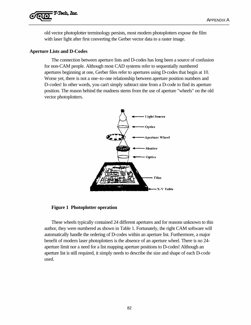
APPENDIX A
82
old vector photoplotter terminology persists, most modern photoplotters expose the film with laser light after first converting the Gerber vector data to a raster image.
Aperture Lists and D-Codes
The connection between aperture lists and D-codes has long been a source of confusion for non-CAM people. Although most CAD systems refer to sequentially numbered apertures beginning at one, Gerber files refer to apertures using D-codes that begin at 10. Worse yet, there is not a one-to-one relationship between aperture position numbers and D-codes! In other words, you can't simply subtract nine from a D-code to find its aperture position. The reason behind the madness stems from the use of aperture "wheels" on the old vector photoplotters.
Figure 1 Photoplotter operation
These wheels typically contained 24 different apertures and for reasons unknown to this author, they were numbered as shown in Table 1. Fortunately, the right CAM software will automatically handle the ordering of D-codes within an aperture list. Furthermore, a major benefit of modern laser photoplotters is the absence of an aperture wheel. There is no 24-aperture limit nor a need for a list mapping aperture positions to D-codes! Although an aperture list is still required, it simply needs to describe the size and shape of each D-code used.
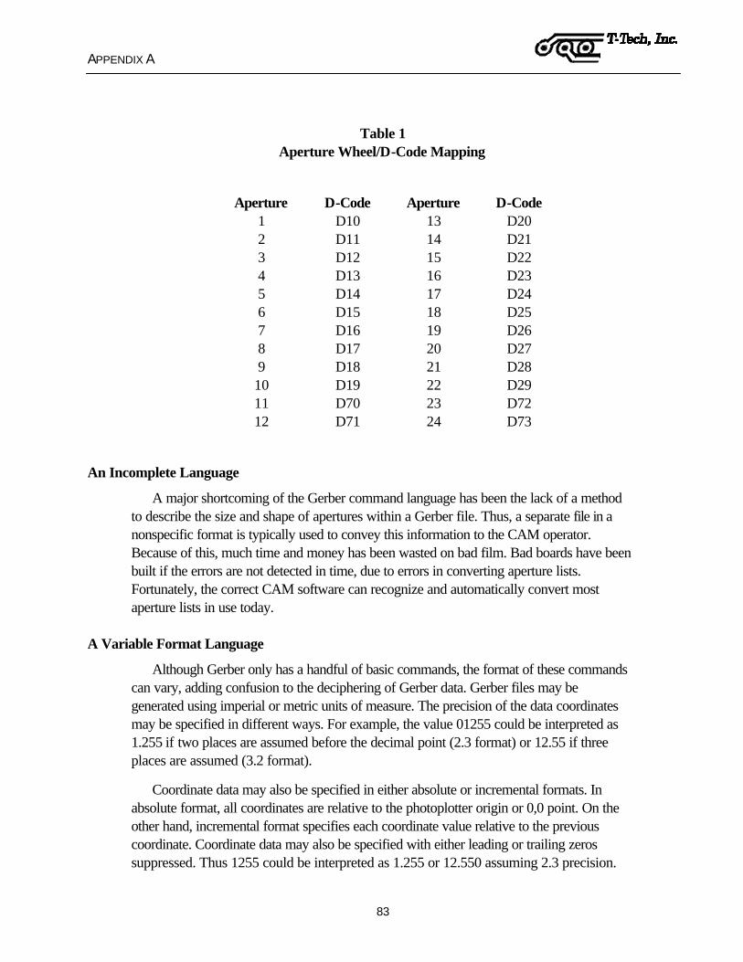
APPENDIX A
83
Table 1 Aperture Wheel/D-Code Mapping
Aperture D-Code Aperture D-Code
1 D10 13 D20 2 D11 14 D21 3 D12 15 D22 4 D13 16 D23 5 D14 17 D24 6 D15 18 D25 7 D16 19 D26 8 D17 20 D27 9 D18 21 D28 10 D19 22 D29 11 D70 23 D72 12 D71 24 D73
An Incomplete Language
A major shortcoming of the Gerber command language has been the lack of a method to describe the size and shape of apertures within a Gerber file. Thus, a separate file in a nonspecific format is typically used to convey this information to the CAM operator. Because of this, much time and money has been wasted on bad film. Bad boards have been built if the errors are not detected in time, due to errors in converting aperture lists. Fortunately, the correct CAM software can recognize and automatically convert most aperture lists in use today.
A Variable Format Language
Although Gerber only has a handful of basic commands, the format of these commands can vary, adding confusion to the deciphering of Gerber data. Gerber files may be generated using imperial or metric units of measure. The precision of the data coordinates may be specified in different ways. For example, the value 01255 could be interpreted as 1.255 if two places are assumed before the decimal point (2.3 format) or 12.55 if three places are assumed (3.2 format).
Coordinate data may also be specified in either absolute or incremental formats. In absolute format, all coordinates are relative to the photoplotter origin or 0,0 point. On the other hand, incremental format specifies each coordinate value relative to the previous coordinate. Coordinate data may also be specified with either leading or trailing zeros suppressed. Thus 1255 could be interpreted as 1.255 or 12.550 assuming 2.3 precision.
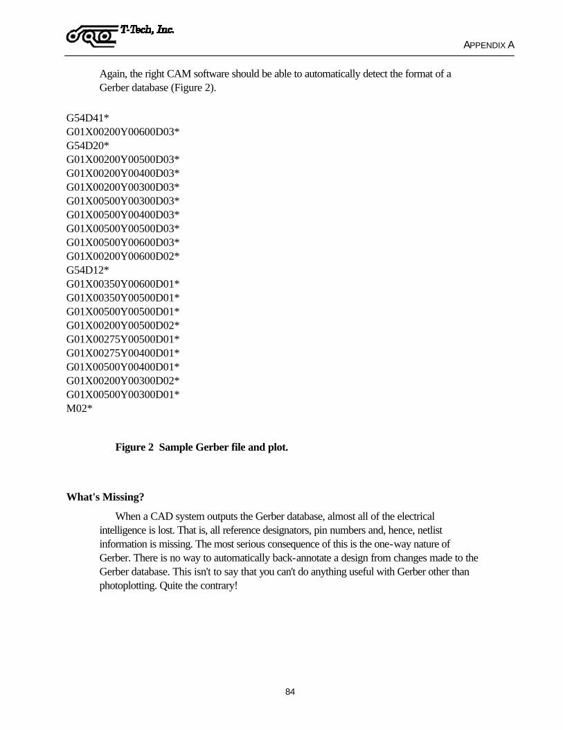
APPENDIX A
84
Again, the right CAM software should be able to automatically detect the format of a Gerber database (Figure 2).
G54D41* G01X00200Y00600D03* G54D20* G01X00200Y00500D03* G01X00200Y00400D03* G01X00200Y00300D03* G01X00500Y00300D03* G01X00500Y00400D03* G01X00500Y00500D03* G01X00500Y00600D03* G01X00200Y00600D02* G54D12* G01X00350Y00600D01* G01X00350Y00500D01* G01X00500Y00500D01* G01X00200Y00500D02* G01X00275Y00500D01* G01X00275Y00400D01* G01X00500Y00400D01* G01X00200Y00300D02* G01X00500Y00300D01* M02*
Figure 2 Sample Gerber file and plot.
What's Missing?
When a CAD system outputs the Gerber database, almost all of the electrical intelligence is lost. That is, all reference designators, pin numbers and, hence, netlist information is missing. The most serious consequence of this is the one-way nature of Gerber. There is no way to automatically back-annotate a design from changes made to the Gerber database. This isn't to say that you can't do anything useful with Gerber other than photoplotting. Quite the contrary!

APPENDIX A
85
Building Intelligence into Gerber
With the right CAM software, it is possible to build netlists using the connectivity of pads and traces. This in turn allows more accurate design rule checking and automatic test point extraction for bare-board testing, for example. Using CAM software and a Gerber database is also the appropriate stage to perform panelization. Since typical CAD systems are not designed to handle multiple copies of identical designs, they are not suitable for panelization. The right CAM software should be capable of placing different designs on the same panel.
Once a CAM operator receives the Gerber database, venting and thieving copper patterns may be added to assist in laminating and plating. Test coupons, registration holes, alignment marks and other fabrication aids may also be incorporated. Layer scaling can be performed to compensate for shrinking or expansion during lamination. Bit-mapped copper area calculations are performed to allow proper plating current. NC drill files are extracted. The drill files should be fully optimized for the overall panel and not individual images. Since the individual PCBs have to be removed from the panel, the data necessary to drive the milling machinery can then be extracted.
Designers Using CAM Tools?
Yes! First and foremost, a designer should view the Gerber database using a WYSIWYG Gerber viewer. Since there are often discrepancies between the CAD database and the generated Gerber database, this will catch most obvious errors. Even better, a CAM tool could be used to run a DRC on the Gerber database. This would catch even the not-so-obvious errors. The benefits of these simple checks are savings in time and money. Besides reducing the service bureau charges and the cost of resending the Gerber database via modem or courier, days or weeks can be saved in turnaround times. Another benefit of using a good Gerber viewer is having a basis for reference when discussing any problems with a service bureau.
Besides simply catching errors, a designer can reduce costs directly by performing more tasks in house and relying less on the service bureau. Using the right CAM software, a designer can perform such tasks as automatic "fix up" of silkscreen data, removal of innerlayer isolated pads and addition of polygon-filled and poured areas. The designer can also reduce the amount of film used in generating artwork for a design by automatically spreading all layers of a design onto one sheet of film!
In addition, the use of CAM software by designers promotes communication and awareness of the entire process from design through production, bridging a gap that has existed since the beginning of PCB design.

APPENDIX A
86
The Politics of Modifying Gerber Databases
Ideally, if problems are detected in a Gerber database, the CAD database would be changed, the schematic would be back-annotated and the Gerber database would be regenerated. In reality, with product life cycles becoming shorter than the design cycle, time is of the essence. If minor problems are found in the Gerber database, it may be more expedient to simply correct them and document the changes so that the CAD database may be corrected at a later time. Regenerating a Gerber database from the CAD system may take many hours depending on the size and complexity of the design. Much time can be saved by detecting and correcting problems directly in the Gerber database. Such corrections should be made in house by the designer. The time spent communicating the problem and then the solution to and from the service bureau may be considerable and is error prone as well.
Conclusion
Learning the fundamentals of Gerber and having the proper CAM tools empowers a designer to maintain control of a design long after it has left the confines of a CAD system. This translates into decreased costs and, more importantly, getting a design into production sooner.
Andy Wise is president of Wise Software Solutions Inc., Beaverton, OR.
Bibliography
Gerber Format Plot Data Format Reference Book Document Number: 0000-000-RM-000. Gerber Scientific Instrument Co., Marketing Services Dept., 83 Gerber Rd. West, South Windsor, CT 06074.
EIA-RS-274-D Standard. Electronic Industries Association, Engineering Dept., 2001 Eye St. NW, Washington, DC 20006.

APPENDIX A
87
PHOTOPLOTTING PRINCIPLES The following is reprinted with permission from an article written by Graphicode, Inc:
PHOTOPLOTTING PRINCIPLES
What's a Photoplotter?
A photoplotter is just what the name implies: an plotter that writes using light. A plotter has to be told:
Which tool to use. When to use the tool, and when not to. Where to go next. Whether to go there in a straight line or along an arc.
For a photoplotter, "tool" means specially shaped apertures through which light passes to create a given shape on film. An aperture can be used without movement to make a shape (a "flash") or with movement to make a line or an arc.
There are two major types of photoplotters, "Vector" and "Raster" (or "laser"). Each handles apertures differently.
Vector Photoplotters
Aperture Wheels
Traditionally, the photoplotter counterpart to a pen plotter's pen rack has been the aperture wheel. The aperture wheel is a disk with 24 or 70 apertures arrayed radially along its circumference.
When the photoplotter selects an aperture, the aperture wheel is rotated to place the desired aperture between the light source and the film. Apertures are themselves pieces of film and can be made to any shape required, although in practice this is a time-consuming process and there is a physical limitation on size.
Flash and Draw Apertures
To achieve constant exposure on a vector photoplotter, apertures used for flashing pads are filtered differently than those used for drawing traces. Therefore, Flash and Draw apertures cannot be used interchangeably without risk of localized over-exposure and under-exposure.

APPENDIX A
88
Aperture Wheel Setup for Vector Plotters
The setup of an aperture wheel is an exacting and time consuming process since each aperture in the wheel must be hand-mounted and aligned. In order to avoid repeated setup costs, designers have the photoplotting vendor keep a wheel on file and are forced to always use that same set of apertures. This has obvious drawbacks, both in terms of design flexibility and the ease of migration to other vendors.
Raster (Laser) Plotters
Aperture Lists
Increasingly, vector photoplotters are being replaced by the laser photoplotter, which emulates the older style machine in a raster (bit-map) fashion. While use of the term "aperture" to describe a pad or trace shape persists, the term "aperture wheel" is now being replaced by "aperture list", which implies the greater flexibility now available to the designer.
There are three principle advantages with aperture lists on raster plotters:
Aperture shapes can be easily generated in software, thus eliminating the need to design a physical wheel.
More apertures can be defined on a list.
Allowable apertures sizes are typically (but not always) greater than those imposed by the physical dimensions of an aperture wheel.
Flash and Draw Apertures
No distinction need be made between Flash and Draw aperture types since the light source intensity is constant.
Speed Advantage of Laser Plotters
Laser plotters operate much quicker than vector machines. A complex plot that required hours on a vector machine can usually be performed in ten minutes or less on a laser photoplotter. This decreases turnaround time and in many markets has driven photoplotting costs down.
Talking to Photoplotters
The de facto standard for photoplotter data is the Gerber format, more properly known as RS-274D. The term Gerber refers to the Gerber Scientific Instrument company, a pioneer and leader in photoplotter manufacturing.
RS-274D is a variation on traditional Numerical Control (NC) machine tool languages. It differs from traditional NC formats (i.e. drill data), as far as its use of tool selection codes but is otherwise compatible.

APPENDIX A
89
RS-274D data is organized in "blocks". A block consists of a combination of codes:
Tool selection Setup Movement And, an End Of Block (EOB) character, which only follows a combination of the above codes.
An EOB character is usually an asterisk ('*') or dollar ('$'), optionally followed by a carriage return and line feed.
An RS-274D code consists of a letter D,G,M,X,Y,I or J followed by a numerical value. These codes designate the following:
* - End of Block (end of command)
D - Select aperture, or set aperture use mode
X - Move to X value
Y - Move to Y value
G - Various setup codes
M - Various control codes
I - Relative X location for arc center
J - Relative Y location for arc center
D Codes
D codes have multiple purposes. The first is to control the state of the light being on or off. Valid codes for light state are D01, D02, and D03.
D01 - Light on for next move.
D02 - Light off for next move.
D03 - Flash (Light On, Light Off) after move (effect is limited to block in which appears, ie non-modal). You can also think of a D03 as D02, D01, D02 series of commands linked together.
D codes with values of 10 or greater represent the aperture's position on the list or wheel. It is very important to understand that there is no universal "D10" or "D30". Unlike the D01 , D02, and D03 counterparts which have a fixed meaning (draw, move, flash), D10 and higher values have aperture shapes and dimensions assigned to them by each individual user. Hence, one job's D10 could be a 10 mil Round, when another job's D10 could be a 45 mil Square.

APPENDIX A
90
There are two distinct ways to number an aperture list. The traditional 24 aperture system started with D10 - D19, jumping suddenly to D70 - D71, then back to D20 - D29, ending with D72 - D73. This is still a common format for output for CAD packages, and is still mandatory for old 24 aperture Gerber vector photoplotters.
It is now common to start with D10, then increase numerically in steps of 1 (D10, D11, etc.) continuing up to D70 and beyond, rarely beyond 1000 individual apertures.
X & Y Codes
The X & Y values in the Gerber file determine where the aperture shape and dimension will be positioned and drawn. X & Y values are used as coordinate pairs to determine where the light will be exposed, using the D codes shapes (i.e. D10) and light exposure status (i.e. D01, D02, D03) for drawing lines and arcs, as well as moving between drawing entities.
Here are a few examples of using X & Y codes with D codes.
D10* { Select aperture D10}
X1000Y1000D02* {The D02 tells us that the light will be off, and we move to coordinate position X1000 and Y1000}
X2000Y3000D01* {The D01 tells us that we will draw (light on) to coordinate position X2000 and Y3000}
X5500Y100D03* {The D03 tells us to move to coordinate position X5500 and Y100 with the light off, then flash (turn the light on and off)}
G Codes
G codes are used to configure the photoplotter. Commonly implemented codes include:
G01 - Future X,Y commands are straightline moves
G02 - Future X,Y commands are clockwise arcs
G03 - Future X,Y commands are counterclockwise arcs
G04 - Ignore the rest of this block (used for Comments)
G54 - Prepare to change apertures
G74 - Future arcs are quadrant arcs
G75 - Future arcs are Full 360 arcs
G90 - Absolute data
G91 - Incremental data

APPENDIX A
91
Typically for laser photoplotters, G54 codes are rarely necessary. Older vector plotter controllers may require this preparatory G codes for changing apertures (i.e. G54D10*).
A common situation where G codes are mandatory for all machines is when the data is switching from vectors to arcs and vice versa. When switching from drawing vectors (G01) to drawing arc (G02, G03), the controller must be informed of the change of mode.
Another important case for G codes is when determining if the arc is a quadrant (G74) or Full 360 (G75). Quadrant arcs never cross quadrant boundaries, because the center coordinate offsets (I,J Codes) are always unsigned (even if they are negative!).
Therefore, it requires at least four G74 arcs to draw one complete circle.
Center coordinate offsets for 360 arcs (G75) can be positive or negative, allowing for a single command to draw a complete circle.
In either case, the center coordinates are given relative to the start point of the arc. The most dramatic difference between Quadrant and Full 360 arcs is that a Quadrant arc with identical start and end points has a sweep of 0 degrees, whereas a similar Full 360 arc is a full circle.
The G90 code tells the machine controller that all data following is absolute data. Hence, if following X & Y data follows, the controller will move to the absolute value given by the X & Y value.
G91 tells the machine controller that all data following is incremental data. The machine will move the data by the amount of the X & Y value, rather than to the absolute coordinate point.
Example:
X1000Y1000D02*
X3000Y3000D01*
In absolute mode (G90), the machine will first move to coordinate point X1000 and Y1000 with the light off, then draw a line to coordinate point X3000 and Y3000 with the light on.
In incremental mode (G91) the machine will first move to coordinate point X1000 and Y1000 with the light off, then draw a line to coordinate point X4000 and Y4000 with the light on. This was done by adding X1000 + X3000 = X4000 and Y1000 + Y3000 = Y4000.

APPENDIX A
92
Here are some more examples of G code usage in conjunction with X, Y, and D code values:
G54D10* {Prepare to change aperture position (G54), then select aperture D10}
G01X1000Y1000D02* {Prepare to draw a vector (G01) then turn off the light (D02) and move to coordinate position X1000 and Y1000}
G90* {This block (command) and all future commands will be absolute data}
X2000Y3000D01* {Turn the light on (D01) and move to absolute coordinate position X2000 and Y3000}
G91* {The G91 command tells the controller that this command and all future commands that the data is incremental}
X5500Y100D03* {Turn the light off and move incrementally by a value of X5500 and Y100, then flash (D03) (light on and off)}
M Codes
M codes are used for machine control. Here are the most commonly used:
M00 - Full machine stop. Commonly ignored by many plotters.
M01 - Temporary machine stop. Commonly ignored by many plotters.
M02 - End of Plot.
I & J Codes
When you encounter an I & J code in a Gerber block, you have found an arc command. Arc commands come in two flavors, Full 360 or Quadrant. The Gerber arc command is very complicated, and this section will only briefly describe usage of the Gerber arc.
Full 360 arcs allow the plotter to draw a full circle (360 degrees of arc) in one single command. Quadrant arcs only allow for an arc to be drawn through a maximum of 90 degrees of arc, never crossing a quadrant boundary. Due to this restriction, I and J arc center offset codes can get away with never having a negative value, even if the offsets are negative!
When in a Full 360 arc (G75), only one command is required to draw a circle. In Quadrant mode, the same circle would require at least 4 Quadrant arcs (G74), because a circle goes through all four quadrants.

APPENDIX A
93
Quadrant arcs will always have positively signed I and J values, even if the center offset is actually negative. Full 360 arc center offsets can be signed positively or negatively. A negative I or J is a sure indicator of Full 360 arcs.
Modality
It is often the case with Gerber data that when moving from one XY coordinate point to another XY coordinate point, the X or Y value will not change. Likewise, it is likely that if the plotter is drawing a line with multiple segments, the segments will be connected and the light stays on from segment to segment.
In both of these cases, there are redundant commands, making the plot data file larger than necessary. RS-274D allows you to omit this redundant data. This example shows a box being drawn with four corners.
Non Modal Data Modal Data
X0000Y0000D02* X1000Y1000D02*
X0000Y1000D01* Y1000D01*
X1000Y1000D01* X1000*
X1000Y0000D01* Y0000*
X0000Y0000D01* X0000*
From this example, a large amount of data has not been written, thus reducing the final data file size.
Establishing the Decimal Point
A numerical value in RS-274D data has an integer and a decimal part, but the decimal point ('.') is not a valid RS-274D character. Thus, decimal values are written as a string of integers. The implicit position of the decimal point is determined by three parameters:
Number of integer digits (whole digits) Number of decimal digits (precision) Zero suppression.
For example: In a system with integer digits=n and decimal digits=m (an "n,m" system), a numerical value is written using (n+m) digits.
For example, in a "2,3" format the value 12.345 is written "12345". In a "2,4" format, the same value is written "123450".

APPENDIX A
94
Zero suppression comes in three flavors - leading, trailing and none. The idea of zero suppression is to reduce data file sizes by eliminating unneeded 0 characters. The simplest and most common form of zero suppression is leading zero suppression.
In a "2,4" format, with no zero suppression, the value 0.0100 would be 00 + 01000, written as "000100", but with leading zero suppression the same value is written as "100".
With trailing zero suppression the same value 0.0100 would be written as "0001".
How To Describe Data Formats
Gerber data and other XY languages use a standard method for describing the data format.
Two examples include: "2,3 leading inch" or "3,3 trailing metric".
The first number specifies the whole digits used. The second parameter statesthe precision. "Leading" and "trailing" pertain to the zero suppression. And the last part of the description indicates the units. Refer to the above sections if these concepts seem unclear.

APPENDIX B
95
APPENDIX B
LICENSE AGREEMENT AND WARRANTY
END USER LICENSE AGREEMENT
T-Tech, Inc. provides this program and licenses its use. You assume responsibility for the selection of the system to achieve your intended results, and the installation and use of, and results obtained from, the system.
LICENSE You may :
use the system on a single machine. The isolation software may be run on a different machine than the one that controls the milling process. In any event you may only run the isolation on one machine per license and control the system with one machine.
copy the program into any machine readable form for backup purposes in support of the use of the program on the single machine (certain programs, however, may include mechanisms to limit copying; they are marked "copy-protected") and
transfer the system and license to another party if the other party agrees to accept the terms and conditions of this agreement. If you transfer the program, you must at the same time either transfer all copies whether in printed or machine readable form to the same party or destroy any and all copies not transferred. T-Tech, Inc. grants a license to such other party under this agreement and the other party will accept such license by its initial use of the program. If you transfer possession of any copy of the program, in whole or in part, to another party, your license is automatically terminated.
This system contains confidential information belonging to T-Tech and is protected by United States and Canadian copyright law. You must reproduce the copyright notice on any copy of the program.
YOU MAY NOT MODIFY, REVERSE COMPILE, RENT, LEASE, OR DISTRIBUTE ANY PROGRAMS FROM THIS SYSTEM OR ANY COPY, IN WHOLE OR IN PART.

APPENDIX B
96
TERMS The license is effective until terminated. You may terminate it at any time by destroying the program together with all copies and returning the Hardware Protection Device (Key). You will also terminate upon conditions herein or if you fail to comply with terms or conditions stated herein. You agree upon termination to destroy the program together with all copies.
PRODUCT DESCRIPTION: The Quick Circuit system consists of two pieces: the milling table and the controller. In addition you may have purchased the clean room vacuum system that is an average sized vacuum*. This vacuum may be placed in a cabinet since the motor is cooled internally. This may not be necessary since it runs at only 67dB. The vacuum should be within 10 feet of the milling table. The cable between the table and the controller is approximately 4 feet long. The cable between the computer and the controller is a serial computer cable. We recommend that you keep the computer in close proximity to the Quick Circuit system.
If your machine is equipped with an air cylinder to control the head assembly, you will also receive a pneumatic controller.
* Some type of vacuum system is required for operation of system.
PRODUCT WARRANTY T-Tech, Inc. guarantees its Quick Circuit machine to be free from defects in material and workmanship for a period of one year from the date of original purchase. T-Tech's obligation under this warranty is limited to repair or replacement of any part or product, which following T-Tech's examination appears to be defective. Under no circumstances shall T-Tech be liable for loss, damage, cost of repair or consequential damages of any kind which have been caused by neglect, abuse, or improper operation of equipment, or shipment to T-Tech in any container other than the original shipping container and packaging. T-Tech is in no way liable for damages relating to delays in production or any damages from any lawsuit concerning any product that features boards produced by Quick Circuit.
SERVICE CONTRACT: T-Tech offers an annually renewable service agreement. For specific details and pricing please contact a T-Tech customer support representative