Embed Size (px)
Citation preview

Qucs
A Description
Verilog-AMS interface
Stefan JahnHelene Parruitte
Copyright c© 2006 Helene Parruitte <[email protected]>Copyright c© 2007 Stefan Jahn <[email protected]>
Permission is granted to copy, distribute and/or modify this document under theterms of the GNU Free Documentation License, Version 1.1 or any later versionpublished by the Free Software Foundation. A copy of the license is included inthe section entitled ”GNU Free Documentation License”.
Introduction
Verilog-AMS is a hardware description language. It can be used to specify theanalogue behaviour of compact device models. Usually these are C or C++ im-plementations in analogue simulators. The effort to implement modern compactmodels in C/C++ is quite high compared to the description in Verilog-AMS.
ADMS
The software ADMS (see http://mot-adms.sourceforge.net) allows Verilog-AMS descriptions to be translated into any other programming language. It gen-erates a structured XML tree representing the compact device model description.
Simulator specific API
C/C++ source file(s)
Simulator specific API
header file(s)Documentation
admsXml:
Language transform
using admst
Verilog−AMS
source file
admsXml:
ADMS internal
data tree
Figure 1: ADMS data flow
The internal XML tree is used to generate ready-to-compile C or C++ code whichis specific to the simulators API. The code generator is able to produce
• evaluation of device equations (current and charge) including their deriva-tives,
• glue code for the simulator API,
• documentation and
• any other data described by the original Verilog-AMS input file.
1
XML admst scripts
The language transformation uses a language named admst. It is itself a XMLdescription. The command line in order to run a transformation is
$ admsXml <device.va> -e <interface-1.xml> -e <interface-2.xml>
From version 0.0.11 Qucs comes with the following Verilog-AMS transformers
• qucsMODULEcore.xml
creating the actual analogue simulator implementation
• qucsMODULEdefs.xml
creating the parameter descriptions for the analogue simulator
• qucsMODULEgui.xml
creating the implementation for the GUI integration
• qucsVersion.xml
basic admst library
• analogfunction.xml
creating analogue function code
In order to create admst scripts for a simulator it is necessary to understand both,the simulator specific API and how the ADMS data tree items – which are basedon the Verilog-AMS source file describing the model – relate to the API.
The command lines for transforming a Verilog-AMS source file into the appropiateQucs C++ source files are
$ admsXml <device.va> -e qucsVersion.xml -e qucsMODULEcore.xml
$ admsXml <device.va> -e qucsVersion.xml -e qucsMODULEgui.xml
$ admsXml <device.va> -e qucsVersion.xml -e qucsMODULEdefs.xml
$ admsXml <device.va> -e analogfunction.xml
each creating an appropriate *.cpp and *.h file.
The admst language is used to traverse the internal tree. The tree’s root is definedby the Verilog-AMS module definition.
module dev i c e ( node1 , node2 , . . . )// module d e f i n i t i o n s and code
endmodule
2
Short introduction into the admst language syntax
Usually the admst language instructions are basically formed as
<a d m s t : i n s t r u c t i o n argument = . . .>. . .
</ a dm s t : i n s t r u c t i o n>
or
<a d m s t : i n s t r u c t i o n argument = . . . />
Any other text outside these instruction is output to the console or into an appro-priate file. Some of the most important language construct are listed below.
• Traversing a list: The construct allows to traverse all children of the selectedbranch.
<admst : for−each s e l e c t=”/module ”>. . .
</ admst : for−each>
• Defining and using variables: Values from the data tree can be put intonamed and typed variables which are then accessible using the $ operator.
<admst:value−o f s e l e c t=”name”><admst :va r i ab l e name=”module ” s e l e c t=”%s ”>
• Opening a file: Printed text (see below) is output into the given file.
<admst:open f i l e=”$module . cpp ”>. . .
</ admst:open>
• Output text: Special characters must be encoded (e.g. " → " < →< > → > and \n → \\n).
<admst : text format=”This i s a t ext . ”/>
• Definition of a function: Functions in admst are called templates.
<admst:template match=”name of funct ion ”>. . .
</ admst:template>
• Running a function: Templates are applied to parts of the internal data tree.
3
<admst:apply−templates s e l e c t=” d a t e t r e e r o o t f o r f u n c t i o n ”match=”name of funct ion ”/>
• Comments:
< !−− t h i s i s a comment −−>
Analogue simulator script
The analogue simulator implementation consists of several parts. For each type ofsimulation appropriate functions must be implemented.
• DC simulationmodule::initDC (void),module::restartDC (void) andmodule::calcDC (void)
• AC simulationmodule::initAC (void) andmodule::calcAC (nr_double_t)
• S-parameter simulationmodule::initSP (void) andmodule::calcSP (nr_double_t)
• Transient simulationmodule::initTR (void) andmodule::calcTR (nr_double_t)
• AC noise simulationmodule::initNoiseAC (void) andmodule::calcNoiseAC (nr_double_t)
• S-parameter noise simulationmodule::initNoiseSP (void) andmodule::calcNoiseSP (nr_double_t)
• Harmonic simulationmodule::initHB (int) andmodule::calcHB (int)
These functions go into the module.core.cpp file. An appropriate module.core.hheader file is also created.
4
In case the Verilog-AMS source file contains analog functions in the module defi-nition, e.g.
analog function real name ;input x ;real x ;begin
name = x ∗ x ;end
endfunction
the analogfunction.xml script produces the appropriate C/C++ and header files
• module.analogfunction.cpp
• module.analogfunction.h.
The ADMS language transformer is aware of how analogue simlators solve a net-work of linear and non-linear devices. The general Newton-Raphson algorithm fora DC simulation used in SPICE-like simulators as well as in Qucs can be expressedas
J (m) ·V (m+1) = J (m) ·V (m) − f(V (m)
)= I
(m)lin + I
(m)nl − J
(m)nl ·V
(m)(1)
whereas J denotes the Jacobian
J (m) =∂f (V )
∂V
∣∣∣∣V (m)
(2)
There are basically two types of contributions supported by ADMS: currents andcharges. The appropiate Jacobian matrices are
J (m) = J(m)I + J
(m)Q =
∂I (V )
∂V
∣∣∣∣V (m)︸ ︷︷ ︸
“static”
+∂Q (V )
∂V
∣∣∣∣V (m)︸ ︷︷ ︸
“dynamic”
= G + C (3)
consisting of two real valued matrices G (conductance/transconductance matrix)and C (capacitance/transcapacitance matrix).
In the Verilog-AMS desciptions only the current and charge contributions are men-tioned. The appropriate derivatives are meant to be automatically formed by thelanguage translator ADMS.
I ( c i , e i ) <+ i t ; // current c on t r i b u t i onI ( s i , c i ) <+ ddt ( Qjs ) ; // charge c on t r i b u t i on
5

The right-hand side of eq. (1) consists of the linear and non-linear currents of thenetwork as well as the Jacobian matrix multiplied by the voltage vector. Sincedevices are usually uncorrelated both parts can be computed directly on a perdevice basis.
Current limitations of ADMS
The following section contains some simple examples demonstrating which Verilog-AMS statements can be successfully handled by ADMS and which not.
Example 1
There was a bug in the admst scripts. They failed to place the function calls ofanalogue functions correctly. This has been fixed.
module diode (a , c ) ;inout a , c ;e l e c t r i c a l a , c ;
analog function real cur rent ;input i s , v ;begin
cur rent = i s ∗ ( exp ( v / 26e−3) − 1 ) ;end
endfunction
real Vd;real Id ;
analog beginVd = V(a , c ) ;Id = cur rent (1 e−15, Vd ) ;I ( a , c ) <+ Id ;
end
endmodule
Example 2
It is not allowed to mix current and charge contributions in assignments. Mixingboth emits wrong C/C++ code. It accounts the current to be a charge in thiscase.
6

module diode (a , c ) ;inout a , c ;e l e c t r i c a l a , c ;
real Vd, Id , Is , Cp ;
analog beginI s = 1e−15;Cp = 1e−12;Vd = V(a , c ) ;Id = I s ∗ ( exp (Vd / 26e−3) − 1 ) ;
// not a l l owed in ADMSI ( a , c ) <+ Id + ddt (Cp∗V(a , c ) ) ;
// a l l owed in ADMSI ( a , c ) <+ Id ;I ( a , c ) <+ ddt (Cp∗V(a , c ) ) ;
end
endmodule
Example 3
The following example is rejected by the admst scripts with this error message.
[info] admsXml-2.2.4 Oct 18 2006 19:50:46
[fatal] qucsVersion.xml:1497:admst:if[lhs]: missing node source/insource
An immediate potential on the right hand side is not allowed embedded in afunction.
module diode (a , c ) ;inout a , c ;e l e c t r i c a l a , c ;
real Id , I s ;
analog beginI s = 1e−15;Id = I s ∗ ( exp (V(a , c ) / 26e−3) − 1 ) ;
7
// not a l l owed in ADMSI ( a , c ) <+ I s ∗ ( exp (V(a , c ) / 26e−3) − 1 ) ;
// a l l owed in ADMSI ( a , c ) <+ Id ;
end
endmodule
Example 4
Potentials on the left-hand side of contribution assignments are not allowed. Thiskind of assignment emits wrong C/C++ code.
module diode (a , c ) ;inout a , c ;e l e c t r i c a l a , c ;
real Id , I s ;real Rp;
analog beginRp = 1e9 ;I s = 1e−15;Id = I s ∗ ( exp (V(a , c ) / 26e−3) − 1 ) ;I ( a , c ) <+ Id ;
// a l l owed in ADMSI ( a , c ) <+ V(a , c ) / Rp ;
// not a l l owed in ADMSV(a , c ) <+ I (a , c ) ∗ Rp;
end
endmodule
Code for the GUI integration
The admst script for the GUI creates files according to its API. Basically itproduces the list of parameters as well their descriptions (if available) in a property
8
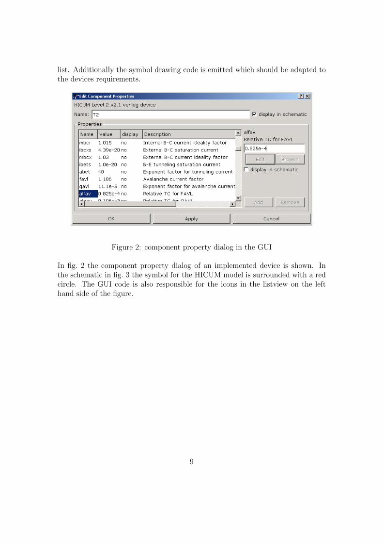
list. Additionally the symbol drawing code is emitted which should be adapted tothe devices requirements.
Figure 2: component property dialog in the GUI
In fig. 2 the component property dialog of an implemented device is shown. Inthe schematic in fig. 3 the symbol for the HICUM model is surrounded with a redcircle. The GUI code is also responsible for the icons in the listview on the lefthand side of the figure.
9

Figure 3: schematic with the HICUM transistor symbol
Adding Verilog-AMS devices to Qucs
The section gives an overview how to add a Verilog-AMS model to Qucs in a step-by-step manner. Be aware that the description is meant for advanced users partlyfamiliar with the usual GNU/Linux build system and C/C++ programming.
The Verilog-AMS source file
The starting point of a new Verilog-AMS model in Qucs is the Verilog-AMS sourcefile which must be aware of the discussed ADMS limitations. The example we aregoing to discuss is a simple diode model shown in the following listing containedin the diode.va file.
‘ include ” d i s c i p l i n e s . vams ”‘ include ”cons tant s . vams ”
// ADMS s p e c i f i c d e f i n i t i o n s
10
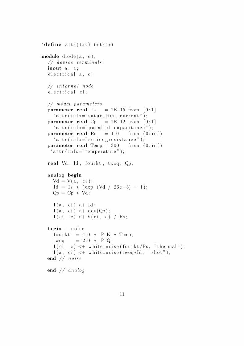
‘define a t t r ( txt ) (∗ txt ∗)
module diode (a , c ) ;// dev i c e t e rmina l sinout a , c ;e l e c t r i c a l a , c ;
// i n t e r n a l nodee l e c t r i c a l c i ;
// model parametersparameter real I s = 1E−15 from [ 0 : 1 ]
‘ a t t r ( i n f o=”s a t u r a t i o n cur rent ” ) ;parameter real Cp = 1E−12 from [ 0 : 1 ]
‘ a t t r ( i n f o=” p a r a l l e l capac i tance ” ) ;parameter real Rs = 1 .0 from ( 0 : i n f )
‘ a t t r ( i n f o=” s e r i e s r e s i s t a n c e ” ) ;parameter real Temp = 300 from ( 0 : i n f )
‘ a t t r ( i n f o=”temperature ” ) ;
real Vd, Id , fourkt , twoq , Qp;
analog beginVd = V(a , c i ) ;Id = I s ∗ ( exp (Vd / 26e−3) − 1 ) ;Qp = Cp ∗ Vd;
I ( a , c i ) <+ Id ;I ( a , c i ) <+ ddt (Qp) ;I ( c i , c ) <+ V( c i , c ) / Rs ;
begin : n o i s ef ou rk t = 4 .0 ∗ ‘P K ∗ Temp;twoq = 2 .0 ∗ ‘P Q ;I ( c i , c ) <+ whi t e no i s e ( f ou rk t /Rs , ”thermal ” ) ;I ( a , c i ) <+ whi t e no i s e ( twoq∗ Id , ”shot ” ) ;
end // no i se
end // analog
11
endmodule
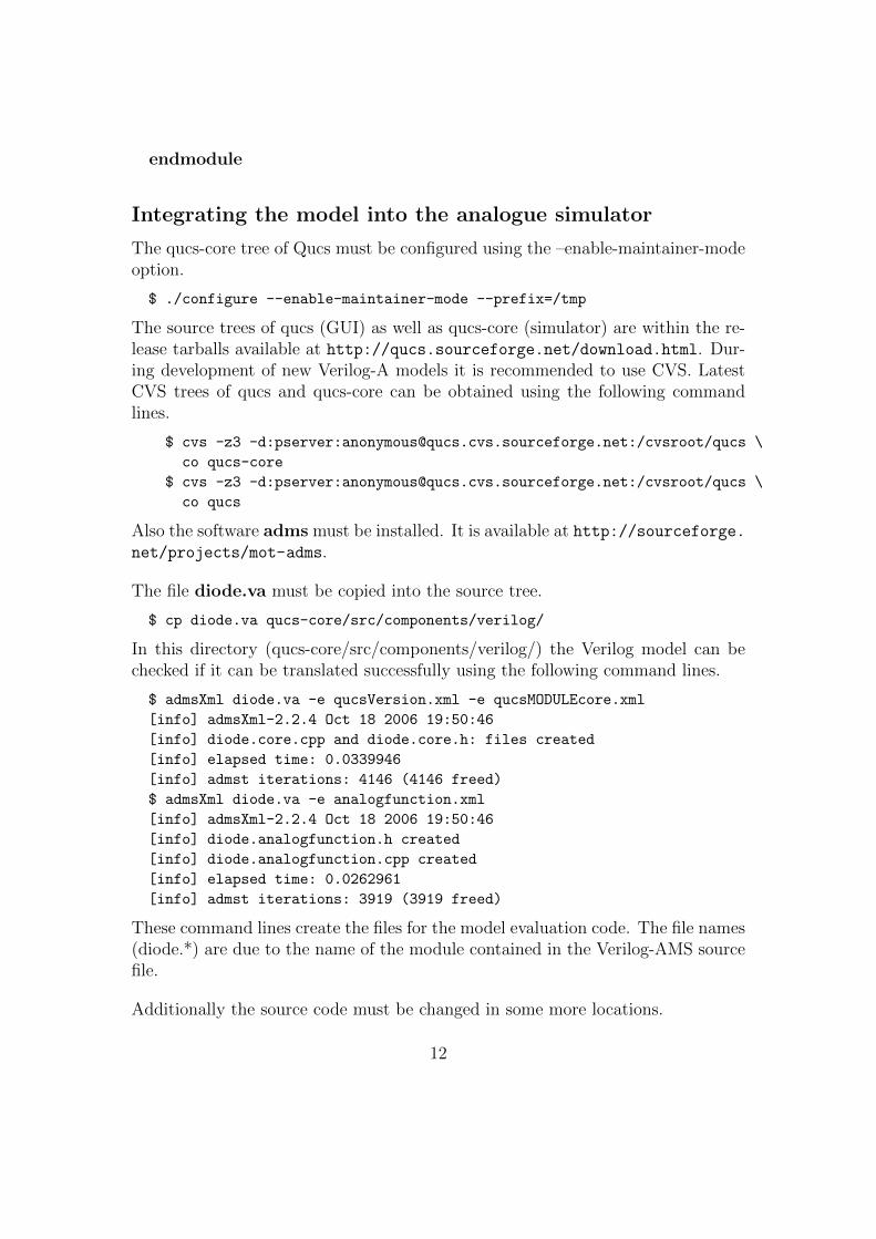
Integrating the model into the analogue simulator
The qucs-core tree of Qucs must be configured using the –enable-maintainer-modeoption.
$ ./configure --enable-maintainer-mode --prefix=/tmp
The source trees of qucs (GUI) as well as qucs-core (simulator) are within the re-lease tarballs available at http://qucs.sourceforge.net/download.html. Dur-ing development of new Verilog-A models it is recommended to use CVS. LatestCVS trees of qucs and qucs-core can be obtained using the following commandlines.
$ cvs -z3 -d:pserver:[email protected]:/cvsroot/qucs \
co qucs-core
$ cvs -z3 -d:pserver:[email protected]:/cvsroot/qucs \
co qucs
Also the software adms must be installed. It is available at http://sourceforge.net/projects/mot-adms.
The file diode.va must be copied into the source tree.
$ cp diode.va qucs-core/src/components/verilog/
In this directory (qucs-core/src/components/verilog/) the Verilog model can bechecked if it can be translated successfully using the following command lines.
$ admsXml diode.va -e qucsVersion.xml -e qucsMODULEcore.xml
[info] admsXml-2.2.4 Oct 18 2006 19:50:46
[info] diode.core.cpp and diode.core.h: files created
[info] elapsed time: 0.0339946
[info] admst iterations: 4146 (4146 freed)
$ admsXml diode.va -e analogfunction.xml
[info] admsXml-2.2.4 Oct 18 2006 19:50:46
[info] diode.analogfunction.h created
[info] diode.analogfunction.cpp created
[info] elapsed time: 0.0262961
[info] admst iterations: 3919 (3919 freed)
These command lines create the files for the model evaluation code. The file names(diode.*) are due to the name of the module contained in the Verilog-AMS sourcefile.
Additionally the source code must be changed in some more locations.
12

• src/components/component.h
In this file it is necessary to add the line
#include "verilog/diode.core.h"
• src/components/component_id.h
The file contains unique component identifiers. It is necessary to add theVerilog modules name.
enum circuit_type {
CIR_UNKNOWN = -1,
...
// verilog devices
CIR_diode,
...
};
• src/input.cpp
In order to be able to instantiate the new model the file must be modified asfollows.
// The function creates components specified by the type of component.
circuit * input::createCircuit (char * type) {
if (!strcmp (type, "Pac"))
return new pac ();
...
else if (!strcmp (type, "diode"))
return new diode ();
logprint (LOG_ERROR, "no such circuit type ‘%s’\n", type);
return NULL;
}
• src/qucsdefs.h
Finally the properties including their range definitions must be added to thisfile. The appropiate file can be obtained using the following command line.
$ admsXml diode.va -e qucsVersion.xml -e qucsMODULEdefs.xml
[info] admsXml-2.2.4 Oct 18 2006 19:50:46
[info] diode.defs.h: file created
[info] elapsed time: 0.0335337
[info] admst iterations: 4294 (4294 freed)
The emitted file diode.defs.h looks like
13
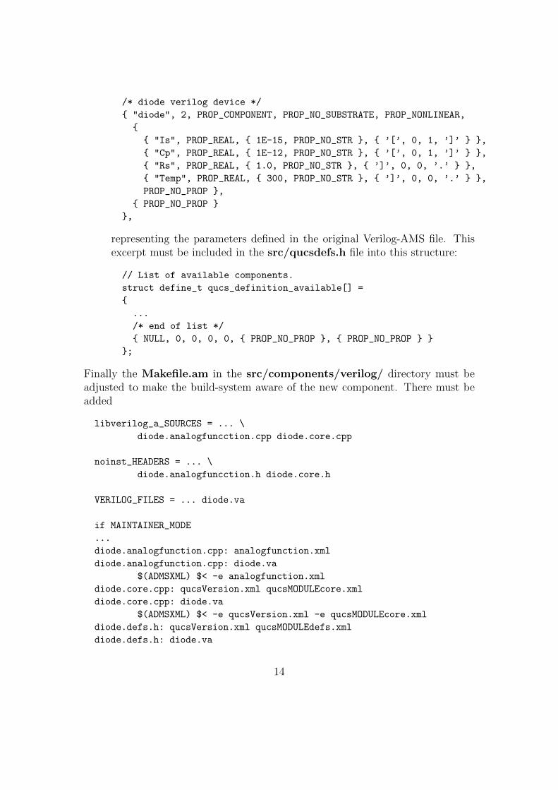
/* diode verilog device */
{ "diode", 2, PROP_COMPONENT, PROP_NO_SUBSTRATE, PROP_NONLINEAR,
{
{ "Is", PROP_REAL, { 1E-15, PROP_NO_STR }, { ’[’, 0, 1, ’]’ } },
{ "Cp", PROP_REAL, { 1E-12, PROP_NO_STR }, { ’[’, 0, 1, ’]’ } },
{ "Rs", PROP_REAL, { 1.0, PROP_NO_STR }, { ’]’, 0, 0, ’.’ } },
{ "Temp", PROP_REAL, { 300, PROP_NO_STR }, { ’]’, 0, 0, ’.’ } },
PROP_NO_PROP },
{ PROP_NO_PROP }
},
representing the parameters defined in the original Verilog-AMS file. Thisexcerpt must be included in the src/qucsdefs.h file into this structure:
// List of available components.
struct define_t qucs_definition_available[] =
{
...
/* end of list */
{ NULL, 0, 0, 0, 0, { PROP_NO_PROP }, { PROP_NO_PROP } }
};
Finally the Makefile.am in the src/components/verilog/ directory must beadjusted to make the build-system aware of the new component. There must beadded
libverilog_a_SOURCES = ... \
diode.analogfuncction.cpp diode.core.cpp
noinst_HEADERS = ... \
diode.analogfuncction.h diode.core.h
VERILOG_FILES = ... diode.va
if MAINTAINER_MODE
...
diode.analogfunction.cpp: analogfunction.xml
diode.analogfunction.cpp: diode.va
$(ADMSXML) $< -e analogfunction.xml
diode.core.cpp: qucsVersion.xml qucsMODULEcore.xml
diode.core.cpp: diode.va
$(ADMSXML) $< -e qucsVersion.xml -e qucsMODULEcore.xml
diode.defs.h: qucsVersion.xml qucsMODULEdefs.xml
diode.defs.h: diode.va
14
$(ADMSXML) $< -e qucsVersion.xml -e qucsMODULEdefs.xml
diode.gui.cpp: qucsVersion.xml qucsMODULEgui.xml
diode.gui.cpp: diode.va
$(ADMSXML) $< -e qucsVersion.xml -e qucsMODULEgui.xml
...
else
in order to create the correct build rules.
If everything worked fine then the new Verilog-AMS model is now completelyintegrated into the analogue simulator.
Integrating the model into the GUI
Very likely as the qucs-core tree in the previous section also the qucs source treemust be configured using the –enable-maintainer-mode option.
$ ./configure --enable-maintainer-mode --prefix=/tmp
Still in the qucs-core/src/components/verilog directory it is now necessary tocreate the C++ code for the GUI using the following command line.
$ admsXml diode.va -e qucsVersion.xml -e qucsMODULEgui.xml
[info] admsXml-2.2.4 Oct 18 2006 19:50:46
[info] diode.gui.cpp and diode.gui.h: files created
[info] elapsed time: 0.0345217
[info] admst iterations: 4146 (4146 freed)
Both the created files diode.gui.cpp and diode.gui.h should be copied to thequcs/qucs/components directory.
Depending on the type of device several changes must be applied to these files.The constructor will basically contain the properties of the device as they are goingto occur in the component property dialog as depicted in fig. 2. Check these ifthey are complete or if some can be left.
diode : : d iode ( ){
Desc r ip t i on = QObject : : t r ( ”diode v e r i l o g dev i ce ” ) ;
Props . append (new Property ( ” I s ” , ”1E−15” , false ,QObject : : t r ( ” s a tu ra t i on cur rent ” ) ) ) ;
Props . append (new Property ( ”Cp” , ”1E−12” , false ,QObject : : t r ( ” p a r a l l e l capac i tance ” ) ) ) ;
15
Props . append (new Property ( ”Rs” , ”1 .0 ” , false ,QObject : : t r ( ” s e r i e s r e s i s t a n c e ” ) ) ) ;
Props . append (new Property ( ”Temp” , ”300 ” , false ,QObject : : t r ( ”temperature ” ) ) ) ;
. . .}
The diode::info function should be adapted to meet the devices requirements.The BitmapFile should be changed to represent a correct PNG file in the quc-s/bitmaps directory. Both the Name and the bitmap are going to appear in theleft-hand component tab as shown in fig. 3.
Element ∗ diode : : i n f o ( QString& Name, char ∗ &BitmapFile ,bool getNewOne )
{Name = QObject : : t r ( ”Diode ” ) ;BitmapFile = ”diode ” ;
i f ( getNewOne ) return new diode ( ) ;return 0 ;
}
The diode::info pnp() method can be completely deleted. It can be necessaryfor bipolar transistors where two types of devices could be displayed (npn and pnptype). The method must also be deleted from the header file. Also, in this case,the new diode class inherits Component instead of MultiViewComponent.
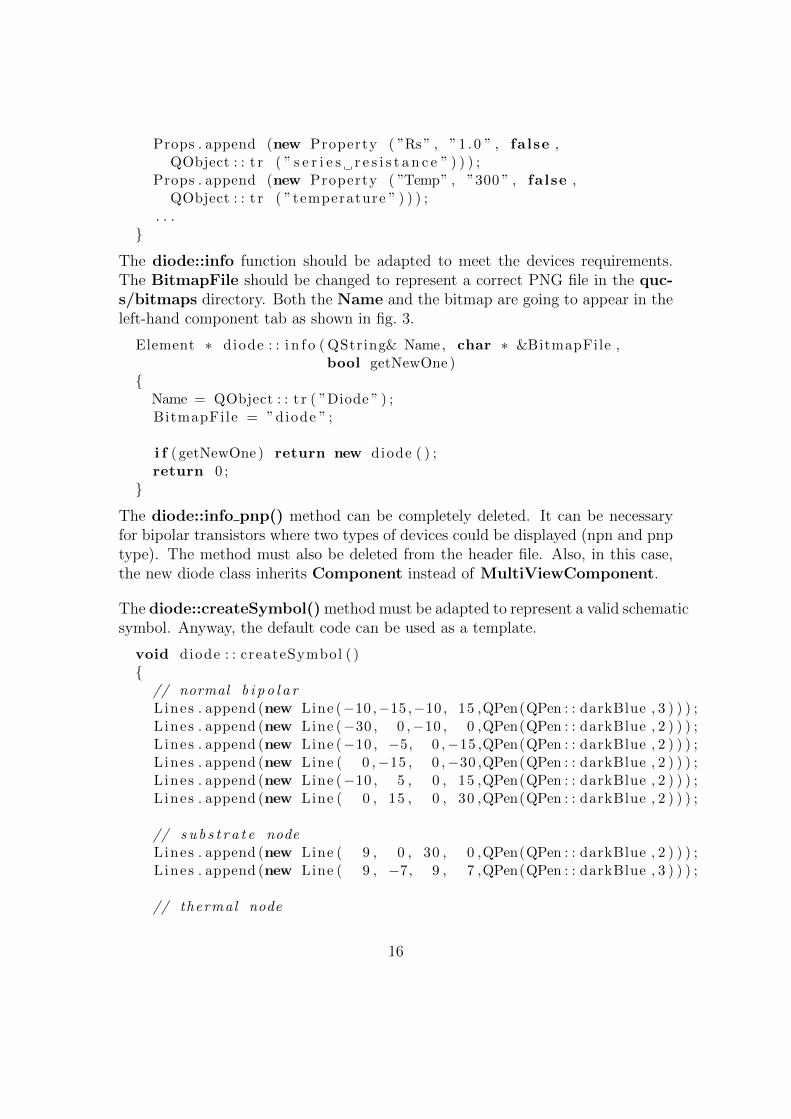
The diode::createSymbol() method must be adapted to represent a valid schematicsymbol. Anyway, the default code can be used as a template.
void diode : : createSymbol ( ){
// normal b i p o l a rLines . append (new Line (−10 ,−15 ,−10 , 15 ,QPen(QPen : : darkBlue , 3 ) ) ) ;L ines . append (new Line (−30 , 0 ,−10 , 0 ,QPen(QPen : : darkBlue , 2 ) ) ) ;L ines . append (new Line (−10 , −5, 0 ,−15 ,QPen(QPen : : darkBlue , 2 ) ) ) ;L ines . append (new Line ( 0 ,−15 , 0 ,−30 ,QPen(QPen : : darkBlue , 2 ) ) ) ;L ines . append (new Line (−10 , 5 , 0 , 15 ,QPen(QPen : : darkBlue , 2 ) ) ) ;L ines . append (new Line ( 0 , 15 , 0 , 30 ,QPen(QPen : : darkBlue , 2 ) ) ) ;
// s u b s t r a t e nodeLines . append (new Line ( 9 , 0 , 30 , 0 ,QPen(QPen : : darkBlue , 2 ) ) ) ;L ines . append (new Line ( 9 , −7, 9 , 7 ,QPen(QPen : : darkBlue , 3 ) ) ) ;
// thermal node
16

Lines . append (new Line (−30 , 20 ,−20 , 20 ,QPen(QPen : : darkBlue , 2 ) ) ) ;L ines . append (new Line (−20 , 17 ,−20 , 23 ,QPen(QPen : : darkBlue , 2 ) ) ) ;
// arrowi f ( Props . g e tF i r s t ()−>Value == ”npn”) {
Lines . append (new Line ( −6, 15 , 0 , 15 ,QPen(QPen : : darkBlue , 2 ) ) ) ;L ines . append (new Line ( 0 , 9 , 0 , 15 ,QPen(QPen : : darkBlue , 2 ) ) ) ;
} else {Lines . append (new Line ( −5, 10 , −5, 16 ,QPen(QPen : : darkBlue , 2 ) ) ) ;L ines . append (new Line ( −5, 10 , 1 , 10 ,QPen(QPen : : darkBlue , 2 ) ) ) ;
}
// termina l d e f i n i t i o n sPorts . append (new Port ( 0 ,−30)) ; // c o l l e c t o rPorts . append (new Port (−30 , 0 ) ) ; // basePorts . append (new Port ( 0 , 3 0 ) ) ; // emi t t e rPorts . append (new Port ( 30 , 0 ) ) ; // s u b s t r a t ePorts . append (new Port (−30 , 2 0 ) ) ; // thermal node
// r e l a t i v e boundingsx1 = −30; y1 = −30;x2 = 30 ; y2 = 30 ;
}
In order to test the component in the GUI it is necessary to modify some moresource code files.
• qucs/qucs.cpp
In this file the new Verilog device will be made available to the componenttab. If a new non-linear device is added then place it here:
pInfoFunc nonlinearComps[] =
{ ... &diode::info, 0};
• qucs/components/component.cpp
The new verilog device must be loadable in the GUI. So in the functiongetComponentFromName() add this:
Component* getComponentFromName(QString& Line)
{
...
case ’d’ : if(cstr == "iode") c = new diode();
break;
...
17

return c;
}
• qucs/components/components.h
In the component header file it is necessary to add:
#include "diode.h"
In order to make the build-sytem aware of the new Verilog model the file qucs/-components/Makefile.am must be modified in the following way.
libcomponents_a_SOURCES = ... \
diode.gui.cpp
noinst_HEADERS = ... \
diode.gui.h
With these steps the component is now fully integrated into the GUI.
Implemented devices
The following sections presents the models already added in Qucs including sometest schematics and simulation results.
HICUM/L2 v2.11 model
The name HICUM was derived from HIgh-CUrrent Model, indicating that HICUMinitially was developed with special emphasis on modelling the operating region athigh current densities which is very important for certain high-speed applications.
The Verilog-AMS source code can be obtained from http://www.iee.et.tu-dresden.
de/iee/eb/hic_new/hic_source.html. The model used in Qucs was a bit mod-ified due to some ADMS limitations.
Some schematics have been setup to verify that the model emits basically thecorrect output values and the source code translations worked properly.
DC simulation
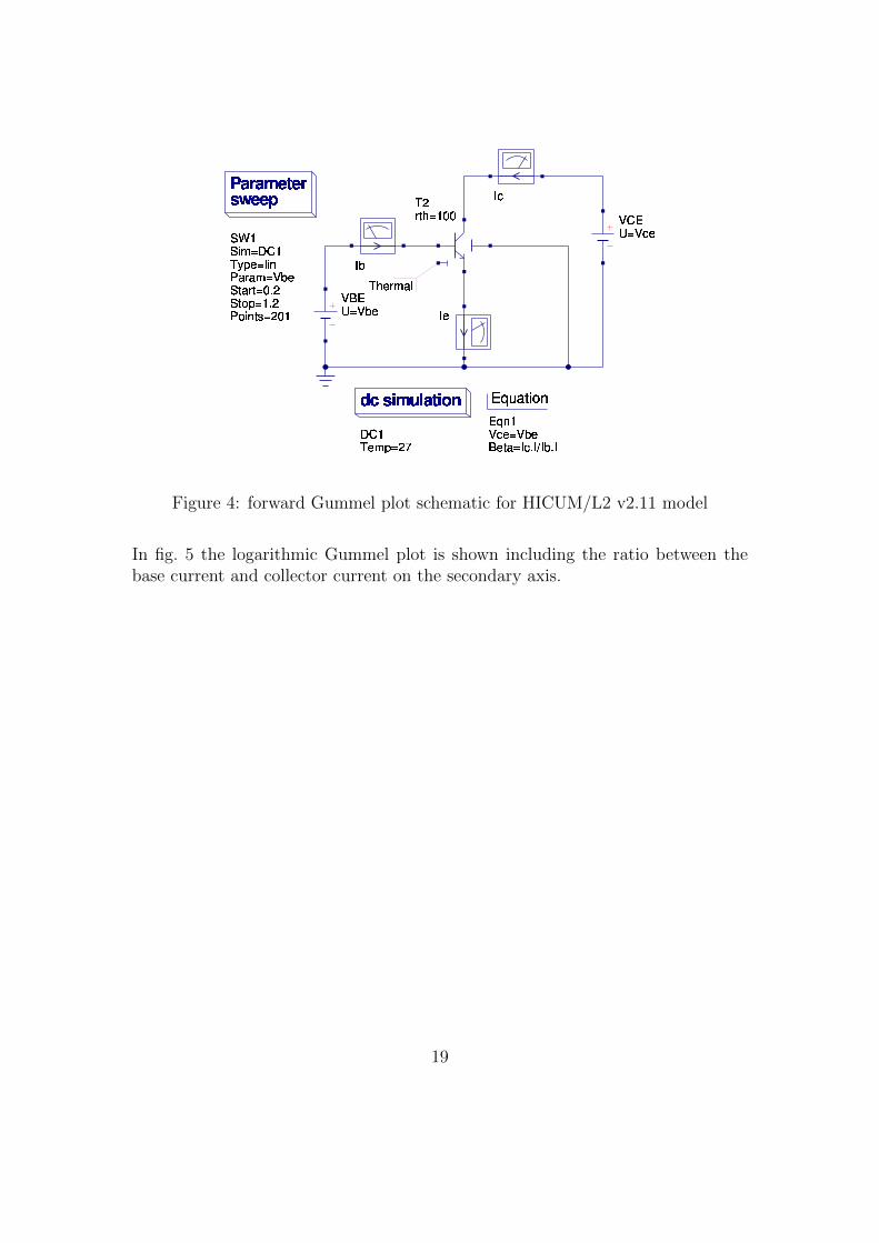
The setup for the forward Gummel plot is depicted in fig. 4. The base-emittervoltage is swept (VBE = 0.2 . . . 1.2) with a constant voltage across the seconddiode VBC = 0.
18
VCEU=VceT2rth=100IcParametersweepSW1Sim=DC1Type=linParam=VbeStart=0.2Stop=1.2Points=201VBEU=VbeIbIedcsimulationDC1Temp=27EquationEqn1Vce=VbeBeta=Ic.I/Ib.IThermal
Figure 4: forward Gummel plot schematic for HICUM/L2 v2.11 model
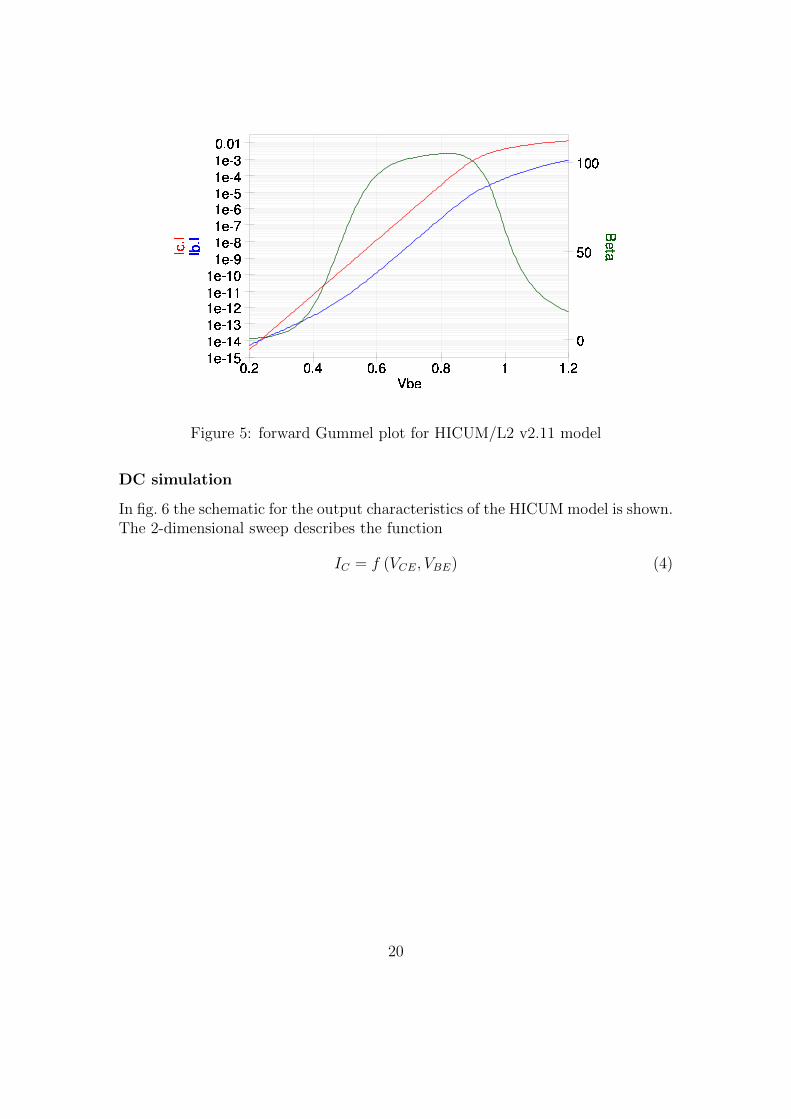
In fig. 5 the logarithmic Gummel plot is shown including the ratio between thebase current and collector current on the secondary axis.
19
0.20.40.60.811.2050100
1e151e141e131e121e111e101e91e81e71e61e51e41e30.01VbeIb.IIc.I Beta
Figure 5: forward Gummel plot for HICUM/L2 v2.11 model
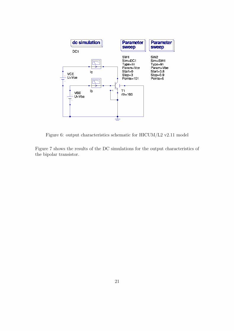
DC simulation
In fig. 6 the schematic for the output characteristics of the HICUM model is shown.The 2-dimensional sweep describes the function
IC = f (VCE, VBE) (4)
20
T1rth=100VCEU=VceVBEU=VbeIbIcParametersweepSW1Sim=DC1Type=linParam=VceStart=0Stop=3Points=101ParametersweepSW2Sim=SW1Type=linParam=VbeStart=0.8Stop=0.9Points=6
dcsimulationDC1
Figure 6: output characteristics schematic for HICUM/L2 v2.11 model
Figure 7 shows the results of the DC simulations for the output characteristics ofthe bipolar transistor.
21

00.511.522.5302e�44e�46e�48e�41e�3Vce
Ic.IFigure 7: output characteristics plot for HICUM/L2 v2.11 model
AC simulation
Figures 8 and 9 depict the schematic and diagrams for an AC simulation in agiven bias point. The current gains magnitude and phase are shown as well as thecharacteristics of the small signal base and collector current in the complex plane(polar plot).
22

T5Type=npnrth=100cth=1e 15X2IbV3U=1V1U=1 IcX3V2U=2dcsimulationDC1acsimulationAC1Type=logStart=1e6Stop=100GHzPoints=50EquationEqn2gain=dB(Ic.i/Ib.i)EquationEqn1phase=phase(Ic.i/Ib.i)
Figure 8: AC simulation schematic for HICUM/L2 v2.11 model
1e61e71e81e91e101e1102040acfrequencygainacfrequency:1.21e+10gain:15.1acfrequency:1.21e+10gain:15.1acfrequency:9.1e+08gain:36.1acfrequency:9.1e+08gain:36.1 1e61e71e81e91e101e1100.02
0.040.040.060.08acfrequencyIc.i Ib.i0.020.040.060.08acfrequency
Ib.iIc.i1e61e71e81e91e101e11$100$500acfrequencyphase
Figure 9: AC simulation plot for HICUM/L2 v2.11 model
23
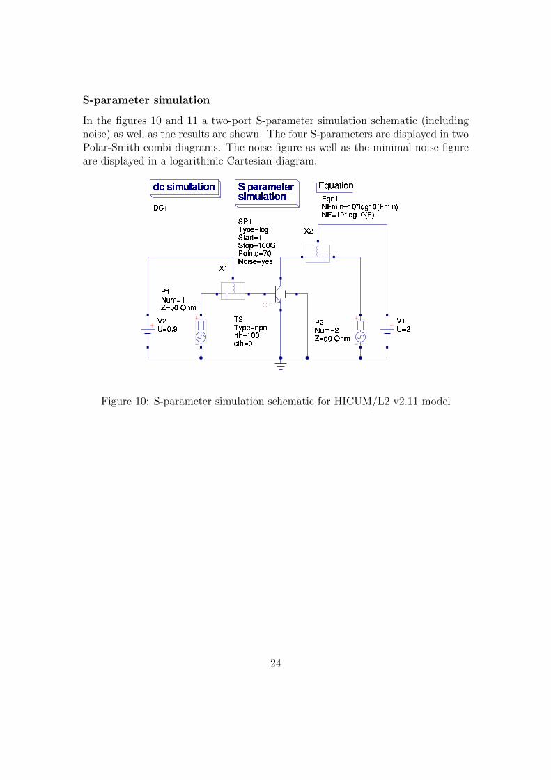
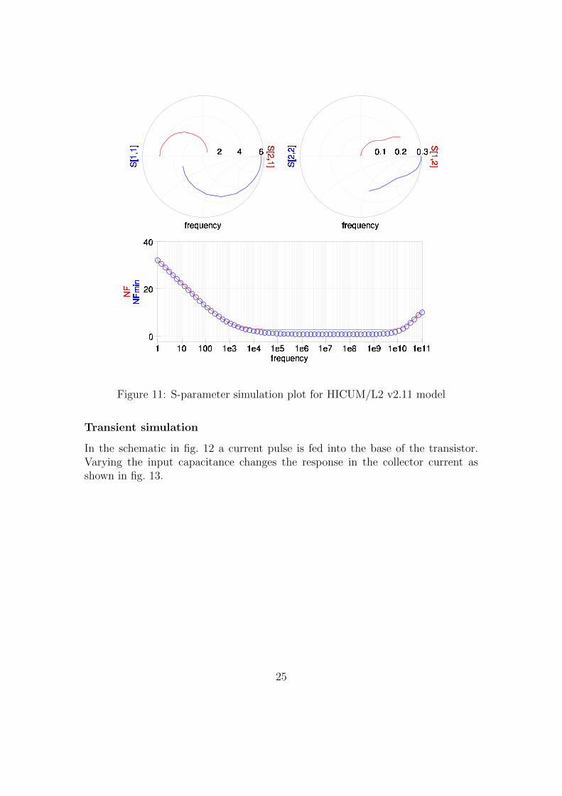
S-parameter simulation
In the figures 10 and 11 a two-port S-parameter simulation schematic (includingnoise) as well as the results are shown. The four S-parameters are displayed in twoPolar-Smith combi diagrams. The noise figure as well as the minimal noise figureare displayed in a logarithmic Cartesian diagram.
X1T2Type=npnrth=100cth=0P1Num=1Z=50OhmV2U=0.9X2P2Num=2Z=50OhmV1U=2SparametersimulationSP1Type=logStart=1Stop=100GPoints=70Noise=yesEquationEqn1NFmin=10*log10(Fmin)NF=10*log10(F)dcsimulationDC1
Figure 10: S-parameter simulation schematic for HICUM/L2 v2.11 model
24
0.10.20.3frequencyS[2,2] S[1,2]246frequencyS[1,1] S[2,1]1101001e31e41e51e61e71e81e91e101e1102040frequencyNFminNF
Figure 11: S-parameter simulation plot for HICUM/L2 v2.11 model
Transient simulation
In the schematic in fig. 12 a current pulse is fed into the base of the transistor.Varying the input capacitance changes the response in the collector current asshown in fig. 13.
25
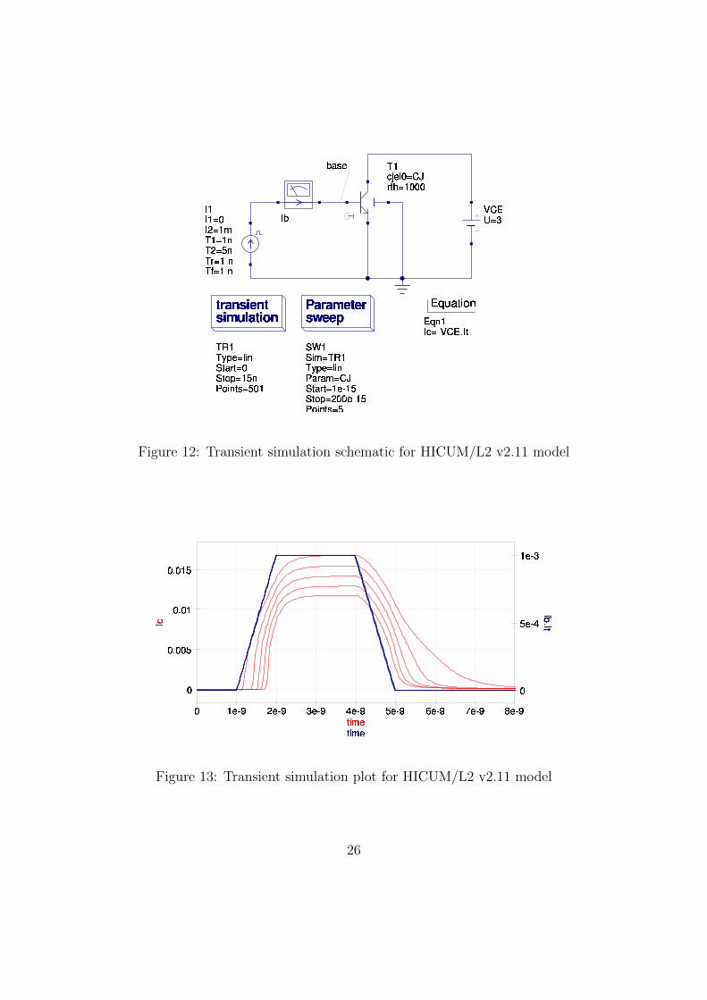
VCEU=3I1I1=0I2=1mT1=1nT2=5nTr=1nTf=1nIbT1cjei0=CJrth=1000
transientsimulationTR1Type=linStart=0Stop=15nPoints=501ParametersweepSW1Sim=TR1Type=linParam=CJStart=1e015Stop=200e015Points=5EquationEqn1Ic=0VCE.It
base
Figure 12: Transient simulation schematic for HICUM/L2 v2.11 model
01e�92e�93e�94e�95e�96e�97e�98e�905e�41e�3
00.0050.010.015
timetimeIc Ib.ItFigure 13: Transient simulation plot for HICUM/L2 v2.11 model
26
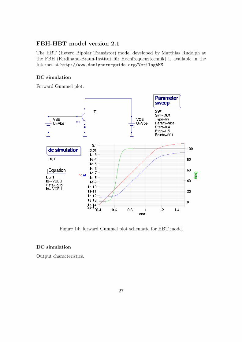
FBH-HBT model version 2.1
The HBT (Hetero Bipolar Transistor) model developed by Matthias Rudolph atthe FBH (Ferdinand-Braun-Institut fur Hochfrequenztechnik) is available in theInternet at http://www.designers-guide.org/VerilogAMS.
DC simulation
Forward Gummel plot.VBEU=Vbe VCEU=VbeParametersweepSW1Sim=DC1Type=linParam=VbeStart=0.4Stop=1.5Points=201T1EquationEqn1Ib=1VBE.IBeta=Ic/IbIc=1VCE.IdcsimulationDC10.40.60.811.21.402040
60801003e1151e1141e1131e1121e1111e1101e191e181e171e161e151e141e130.010.1Vbe
IbIc BetaFigure 14: forward Gummel plot schematic for HBT model
DC simulation
Output characteristics.
27
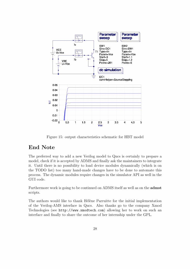
VCEU=VcedcsimulationDC1convHelper=SourceSteppingParametersweepSW1Sim=DC1Type=linParam=VceStart=0Stop=5Points=201ParametersweepSW2Sim=SW1Type=linParam=VbeStart=1.1Stop=1.2Points=6VBEU=VbeIbIcT1
00.511.522.533.544.5560.0260.0100.010.020.030.040.05VceIc.I
Figure 15: output characteristics schematic for HBT model
End Note
The preferred way to add a new Verilog model to Qucs is certainly to prepare amodel, check if it is accepted by ADMS and finally ask the maintainers to integrateit. Until there is no possibility to load device modules dynamically (which is onthe TODO list) too many hand-made changes have to be done to automate thisprocess. The dynamic modules require changes in the simulator API as well in theGUI code.
Furthermore work is going to be continued on ADMS itself as well as on the admstscripts.
The authors would like to thank Helene Parruitte for the initial implementationof the Verilog-AMS interface in Qucs. Also thanks go to the company XmodTechnologies (see http://www.xmodtech.com) allowing her to work on such aninterface and finally to share the outcome of her internship under the GPL.
28


![Verilog HDL - fpga.worldlrv/verilog.pdf · Ken Coffman, “Real world FPGA design with Verilog.” Prentice Hall [2000] Donald E. Thomas, Philip R. Moorby, “The Verilog® Hardware](https://img.dokumen.tips/doc/110x75/5eae29eb016ba60b3a731046/verilog-hdl-fpga-lrvverilogpdf-ken-coffman-aoereal-world-fpga-design-with.jpg)