Embed Size (px)
Citation preview

Quasar II
UPS 10÷40 kVA
User Manual
Item no. (10 kVA)
(15 kVA)
(20 kVA)
(25 kVA)
(30 kVA)
(40 kVA)

Quasar II - UPS 10÷40 kVA Legal Notices
DT0431-E02 2
Legal Notices
Copyright © 2010
All rights reserved
This handbook is protected by copyright.
Copyright by EFFEKTA Regeltechnik GmbH.
All trademarks used are the property of the respective owners.
EFFEKTA® is a registered trademark of EFFEKTA Regeltechnik GmbH.
EFFEKTA Regeltechnik GmbH
Rheinwaldstrasse 34
78628 Rottweil
Germany
March 2010

Quasar II - UPS 10÷40 kVA Contents
DT0431-E02 3
Contents
1. GENERAL OVERVIEW ................................................................................. 5
1.1 UPS – General Description ..................................................................... 5
1.2 Configuration and Additional Equipment ................................................. 7
1.3 Operating Principle ................................................................................ 10
2. INSTALLATION INSTRUCTIONS ................................................................... 13
2.1 General Information ............................................................................... 13
2.2 Receipt and Checking ............................................................................ 13
2.3 Storage .................................................................................................. 14
2.4 UPS Positioning ..................................................................................... 14
2.5 Environmental specifications ................................................................. 17
2.6 Mains Connection Cabling ..................................................................... 17
2.7 UPS Auxiliary connections..................................................................... 24
3. CONTROL PANEL ..................................................................................... 29
3.1 Introduction ............................................................................................ 29
3.2 LCD Control Panel ................................................................................. 30
4. INSTRUCTIONS FOR USING THE UPS ......................................................... 37
4.1 Introduction ............................................................................................ 38
4.2 Power Switches ..................................................................................... 39
4.3 UPS Start-Up ......................................................................................... 40
4.4 Instructions for Switching the System to Manual Bypass Mode ............ 42
4.5 Instructions for Return from Manual Bypass Mode to Normal Mode .... 43
4.6 Instructions for a Complete UPS Shutdown .......................................... 44
4.7 E.P.O. (Emergency Power Off) ............................................................. 45
4.8 Instructions to Start the UPS from Power Save Mode .......................... 45
4.9 Instructions for Switching the System from Power Save Mode to Manual Bypass Mode ........................................................................ 47
Quasar II - UPS 10÷40 kVA Contents
DT0431-E02 4
4.10 Instructions for Return from Manual Bypass Mode to Normal Mode in Power Save Mode. ...................................................... 48
4.11 Instructions for the Complete Shutdown of the UPS in Power Save Mode .................................................................................. 49
4.12 Managing the UPS Battery .................................................................... 50
5. UPS DEVICES IN PARALLEL ..................................................................... 51
5.1 System Set-up ....................................................................................... 51
6. TROUBLESHOOTING ................................................................................. 52
6.1 General Alarms ...................................................................................... 52
6.2 In Case of Fire ....................................................................................... 53
6.3 Faults Due to Load Disorder .................................................................. 53
7. SCHEDULED MAINTENANCE ...................................................................... 54
7.1 Note .................................................................................................. 54

Quasar II - UPS 10÷40 kVA General Overview
DT0431-E02 5
1. General Overview
1.1 UPS – General Description
These UPS series are characterized by their compact construction. They
consist of an outer metal housing with the electronic circuits and power
components inside. All user accessible elements are placed on the rear. The
control panel is located on the front.
The top and side covers can be removed, giving an access to the internal part
of the UPS for service or maintenance purposes.
The user interface panel for monitoring, maintenance and control is located on
the front side of all units.
The terminal block for the electrical connection to the mains, reserve, load,
external batteries, and the main switch, is located on the rear of the unit.
The internal batteries are located in the lower part of the UPS, with access from
the front.
1.1.1 UPS Application Areas
The new UPS family was designed to provide stabilized and filtered power for
sophisticated and sensitive electronic devices, especially data processing
equipment. Quasar II can be used to supply electronic systems in medical
centers, police stations, motorway tunnels, broadcasting stations, banks,
technical and administrative offices, which require a power source that is free
from voltage and frequency variations.
Quasar II - UPS 10÷40 kVA General Overview
DT0431-E02 6
1.1.2 Power and Autonomy
The UPS can use an internal battery block consisting of 60 batteries with
5 - 7.2 or 9 Ah. External battery modules can be added to increase the
autonomy of the UPS.
1.1.3 Safety and Simple Operation
All the UPS elements available for user daily maintenance are insulated and
disconnected from hazardous voltages.
Overload and excessive temperature controls guarantee immediate and
appropriate intervention if one of these conditions should occur during
operation.
The operator can view the UPS status on the front panel and perform shut
down or switching operations easily (see Chapter. 3).9:
The unit is provided with an E.P.O. (Emergency Power Off) function. This is
activated by pressing the button located on the front panel.
An (optional) remote E.P.O switch can be connected to the UPS, to provide
remote emergency power off functionality.
The UPS state can be easily monitored via an (optional) personal computer
and an interactive program or through the (optional) remote display panel,
especially when the UPS is installed in unmonitored areas.
See Chapter 1.2.5 - 1.2.6.

Quasar II - UPS 10÷40 kVA General Overview
DT0431-E02 7
1.2 Configuration and Additional Equipment
1.2.1 Basic Configuration
The UPS is available in the following configurations:
Input Output Power Quasar II
Three-phase input Three-phase output 10÷40 kVA
Three-phase input Single-phase output 10÷40 kVA
Single-phase input Single-phase output 10÷40 kVA
1.2.2 Battery Housing
If the autonomous time provided with the basic configuration is not sufficient,
an additional optional battery housing can be connected to the UPS.
The battery housing can contain up to 2 blocks with 4.5 -5 - 7.2 - 9 Ah
batteries.
1.2.3 Transformer Housing
If a galvanic isolating transformer is required, it can be positioned inside the
UPS housing instead of the internal batteries. In this case an external battery
housing is essential.
The standard transformer is three-phase/three-phase (or single-phase/single-
phase or three-phase/single-phase) with a 1:1 ratio, but it can be supplied with
a different transformation ratio if customer requirements demand this.
Quasar II - UPS 10÷40 kVA General Overview
DT0431-E02 8
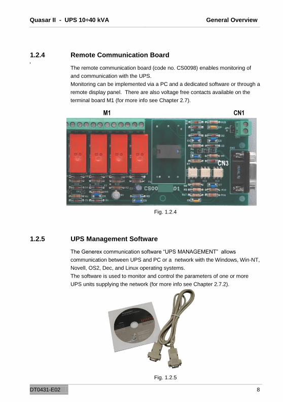
1.2.4 Remote Communication Board
The remote communication board (code no. CS0098) enables monitoring of
and communication with the UPS.
Monitoring can be implemented via a PC and a dedicated software or through a
remote display panel. There are also voltage free contacts available on the
terminal board M1 (for more info see Chapter 2.7).
Fig. 1.2.4
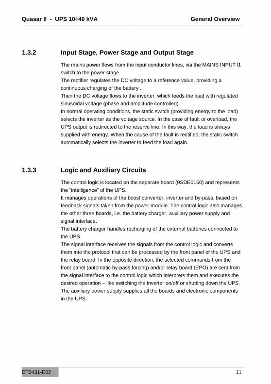
1.2.5 UPS Management Software
The Generex communication software “UPS MANAGEMENT” allows
communication between UPS and PC or a network with the Windows, Win-NT,
Novell, OS2, Dec, and Linux operating systems.
The software is used to monitor and control the parameters of one or more
UPS units supplying the network (for more info see Chapter 2.7.2).
Fig. 1.2.5
M1 CN1
CN3

Quasar II - UPS 10÷40 kVA General Overview
DT0431-E02 9
1.2.6 Remote Display Panel
The remote display panel is used for the remote monitoring of the state of the
UPS. It shows the status of the main UPS blocks with LED indicators and an
acoustic sound in the case of alarm state (for more info see Chapter 2.7.1).
Fig. 1.2.6
1.2.7 Remote E.P.O. Button
The remote E.P.O button provides a reliable way to shut down the unit
immediately and completely, in the event of an emergency (for more info see
Chapter 2.7.2).

Quasar II - UPS 10÷40 kVA General Overview
DT0431-E02 10
I1
I5
I2
I4
I3
==
Mains Input
Output
Manual Bypass Manual Baypass
PFC Inverter Static Switch
Battery
Reserve Input
Bypass
1.3 Operating Principle
The UPS described here is an on-line dual conversion type UPS with automatic
by-pass in compliance with European standard EN62040-1-2. This UPS
performs a dual conversion of the input voltage continuously and without
interruption.
The absence of a direct connection between mains and the load prevents a
transfer of voltage and frequency disturbances. The dual conversion
guarantees that the output energy is always well regulated and has correct
voltage and frequency values, which makes it the ideal tool for the operation of
professional equipment.
When the input voltage exceeds the allowed range or - more frequently - is not
present, the load is supplied by converted energy from the batteries.
The system is supplied with an automatic by-pass. In the event of a UPS fault
or overload, the by-pass connects immediately the load directly to the mains
through a reserve line, making normal operation possible again, without
interruption. See Fig. 1.3.1.
1.3.1 UPS Block Diagram
Fig. 1.3.1
Quasar II - UPS 10÷40 kVA General Overview
DT0431-E02 11
1.3.2 Input Stage, Power Stage and Output Stage
The mains power flows from the input conductor lines, via the MAINS INPUT l1
switch to the power stage.
The rectifier regulates the DC voltage to a reference value, providing a
continuous charging of the battery .
Then the DC voltage flows to the inverter, which feeds the load with regulated
sinusoidal voltage (phase and amplitude controlled).
In normal operating conditions, the static switch (providing energy to the load)
selects the inverter as the voltage source. In the case of fault or overload, the
UPS output is redirected to the reserve line. In this way, the load is always
supplied with energy. When the cause of the fault is rectified, the static switch
automatically selects the inverter to feed the load again.
1.3.3 Logic and Auxiliary Circuits
The control logic is located on the separate board (0SDE0150) and represents
the “intelligence” of the UPS.
It manages operations of the boost converter, inverter and by-pass, based on
feedback signals taken from the power module. The control logic also manages
the other three boards, i.e. the battery charger, auxiliary power supply and
signal interface.
The battery charger handles recharging of the external batteries connected to
the UPS.
The signal interface receives the signals from the control logic and converts
them into the protocol that can be processed by the front panel of the UPS and
the relay board. In the opposite direction, the selected commands from the
front panel (automatic by-pass forcing) and/or relay board (EPO) are sent from
the signal interface to the control logic which interprets them and executes the
desired operation – like switching the inverter on/off or shutting down the UPS.
The auxiliary power supply supplies all the boards and electronic components
in the UPS.

Quasar II - UPS 10÷40 kVA General Overview
DT0431-E02 12
1.3.4 Batteries
The battery set provides energy to the system when the input mains is out of
the allowed range or not present. In all other cases batteries are constantly
recharged by the charger module. In this way the batteries are always ready for
use when required.
1.3.5 Manual Bypass
Manual by-pass is useful in situations when it is necessary to disable the UPS
and keep the load supplied by the mains (i.e.: UPS failure, fault, etc.). This
function can be activated with using the MANUAL BY-PASS (l3) switch, located
in the rear of the UPS (see Chapter 4). Under normal operating conditions, this
circuit breaker remains in the rest position, through being protected by a
mechanical lock (padlock).
1.3.6 Front Panel
The UPS can be administered through the front panel. Using the panel it is
possible to execute commands, display states and measured values and reset
the alarm circuits.
The panel is equipped with an LCD screen used to display the operating status
of the UPS, the load and all types of measured values (see Chapter 3).

Quasar II - UPS 10÷40 kVA Installation Instructions
DT0431-E02 13
2. Installation Instructions
2.1 General Information
This Chapter describes the system installation procedures and deals with the
following subjects:
Receipt and checking
Storage
UPS positioning
Environmental specifications
Assignment and connection to mains
UPS Auxiliary connections
Earth connection
2.2 Receipt and Checking
After unpacking, visually inspect (inside and outside) the UPS and battery
module (if included) to check for any damage that may have occured during
shipping. If there is any damage, inform the shipper or dealer immediately.
Check the supplied material against the packing slip.
The machine has an adhesive identification plate indicating the type, power
and serial number. It is located on the rear of the unit (Fig. 2.2).
Fig. 2.2

Quasar II - UPS 10÷40 kVA Installation Instructions
DT0431-E02 14
2.3 Storage
If the system is not going to be installed immediately it must be stored in an
environment with adequate protection against excessive humidity and sources
of extreme heat (from +5 to +40°C, with humidity less than 95% and without
condensation).
If the battery module is supplied, also make sure that no more than 6
months pass between one battery recharge and the next.
Once this period of time has elapsed, temporarily connect the UPS up to the
mains and run it for the time needed to recharge the batteries.
2.4 UPS Positioning
Fig. 2.4a
All dimensions are in millimeters.
The same housing is used for both series.
Quasar II - UPS 10÷40 kVA Installation Instructions
DT0431-E02 15
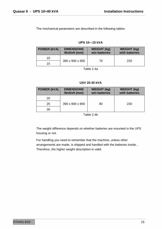
The mechanical parameters are described in the following tables:
UPS 10—15 kVA
POWER (kVA) DIMENSIONS WxDxH (mm)
WEIGHT (kg) w/o batteries
WEIGHT (kg) with batteries
10 390 x 900 x 900 70 220
15
Table 2.4a
USV 20-30 kVA
POWER (kVA) DIMENSIONS WxDxH (mm)
WEIGHT (kg) w/o batteries
WEIGHT (kg) with batteries
20
390 x 900 x 900 80 230 25
30
Table 2.4b
The weight difference depends on whether batteries are mounted in the UPS
housing or not.
For handling you need to remember that the machine, unless other
arrangements are made, is shipped and handled with the batteries inside, .
Therefore, the higher weight description is valid.

Quasar II - UPS 10÷40 kVA Installation Instructions
DT0431-E02 16
All the connections are located on the rear panel and can be reached after
removing the cover, as shown in Fig. 2.4b.
Figure 2.4b shows the cover and the external connections.
1 Protective air cooling grid
2 Communication card slot
3 Fuses
4 Metal cover
Fig. 2.4b
The cable input is located at the bottom of the rear wall, and is accessible after
removing the metal cover (Fig.2.4b).
The cable connections correspond to the UPS configuration and are shown in
Fig.2.6 c/d/e.
1
2
3
4

Quasar II - UPS 10÷40 kVA Installation Instructions
DT0431-E02 17
2.5 Environmental specifications
The room where the UPS is installed must be clean. It must comply with
pollution class 2 (CEI) and be able to dissipate the heat produced by the
machine, as shown in table 2.5a.
Rated power (kVA)
Dissipated power (W)
15 750
30 1440
Table 2.5a
For correct battery ventilation, the room must be able to ensure an exchange of
air equal or greater than shown in table 2.5b.
Air exchange just for battery hydrogen
4.5 Ah batteries 7 Ah batteries 9 Ah batteries
(60 blocks) (60 blocks) (60 blocks)
Table 2.5b
Please note that the average battery lifetime is closely dependant on the
operating temperature. A temperature of around 20°C is normally
recommended.
(If the temperature rises above 20°,the battery life drops by 50% for each 10°
increase).
2.6 Mains Connection Cabling
A layout like the one shown in diagram 2.6 is recommended for the mains
connection. The circuit breakers B-C-D are magnetothermic type without
differential protection, or if this is required, with a triggering current greater than
0.3A, delayed and suitable for load with DC current (type A).
Switch A is used as external BY-PASS.

Quasar II - UPS 10÷40 kVA Installation Instructions
DT0431-E02 18
Block diagram
Fig. 2.6a
Quasar II - UPS 10÷40 kVA Installation Instructions
DT0431-E02 19
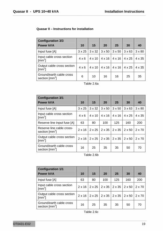
Quasar II – Instructions for installation
Configuration 3/3
Power kVA
10
15
20
25
30
40
Input fuse [A] 3 x 25 3 x 32 3 x 50 3 x 50 3 x 63 3 x 80
Input cable cross section [mm
2]
4 x 6 4 x 10 4 x 16 4 x 16 4 x 25 4 x 35
Output cable cross section [mm
2]
4 x 6 4 x 10 4 x 16 4 x 16 4 x 25 4 x 35
Ground/earth cable cross section [mm
2]
6 10 16 16 25 35
Table 2.6a
Configuration 3/1
Power kVA
10
15
20
25
30
40
Input fuse [A] 3 x 25 3 x 32 3 x 50 3 x 50 3 x 63 3 x 80
Input cable cross section [mm
2]
4 x 6 4 x 10 4 x 16 4 x 16 4 x 25 4 x 35
Reserve line input fuse [A] 63 80 100 125 160 200
Reserve line cable cross-section [mm
2]
2 x 16 2 x 25 2 x 35 2 x 35 2 x 50 2 x 70
Output cable cross section [mm
2]
2 x 16 2 x 25 2 x 35 2 x 35 2 x 50 2 x 70
Ground/earth cable cross section [mm
2]
16 25 35 35 50 70
Table 2.6b
Configuration 1/1
Power kVA
10
15
20
25
30
40
Input fuse [A] 63 80 100 125 160 200
Input cable cross section [mm
2]
2 x 16 2 x 25 2 x 35 2 x 35 2 x 50 2 x 70
Output cable cross section [mm
2]
2 x 16 2 x 25 2 x 35 2 x 35 2 x 50 2 x 70
Ground/earth cable cross section [mm
2]
16 25 35 35 50 70
Table 2.6c

Quasar II - UPS 10÷40 kVA Installation Instructions
DT0431-E02 20
UPS
L1-RESERVE
L2-RESERVE
L3-RESERVE
NEUTRAL
L1-MAINS
L2-MAINS
L3-MAINS
NEUTRAL
A B
C
L1
L2
L3
NEUT
K2K1
K3
DISTRIBUTION PANEL
WARNING
IN ADDITION TO THE CIRCUIT BREAKER AND PROTECTION IT IS
ADVISABLE TO SET UP AN APPROPRIATE CHANGE-OVER
CONTACT ON THE INPUT SIDE OUTSIDE THE UPS TO PROTECT
AGAINST VOLTAGE RETURNS (THIS OPTION IS ALREADY
AVAILABLE IN THE MIZAR SERIES), AS INDICATED IN TABLE
2.6a/2.6b/2.6c AND THE FOLLOWING DRAWING.
If necessary, a system to protect against voltage return in the UPS distribution
panel as shown in diagram 2.6b must be installed for the Alcor series 20-25-
30kVA (option already available in the Mizar series).
A: General mains circuit breaker / switch
C: Automatic switch or at least a fuse for the mains
B: Automatic switch or at least a fuse for the
reserve network
K3: Contactor to protect against return voltage
K1-K2: Additional relays on the change-over contact coil supply
Fig. 2.6b

Quasar II - UPS 10÷40 kVA Installation Instructions
DT0431-E02 21
WARNING
BEFORE CONNECTING THE UPS MAKE SURE THE LINES THAT
CONNECT THE UPS MAINS AND RESERVE INPUTS TO THE
DISTRIBUTION PANEL ARE OPEN AND DISCONNECTED.
MAKE SURE THAT THE BATTERY PANEL SWITCH IS OPEN.
PUT WARNING SIGNS ON THE DISTRIBUTION PANEL AND
BATTERY PANEL TO PREVENT AGAINST ACCIDENTAL ACTIONS.
REAR of the UPS
Disconnect
GND L1 L2 L3 N L1 L2 L3 N L1 L2 L3 N + N - GND
INPUT INPUT UPS OUTPUT BATTERY
MAINS RESERVE
(use only with
separate reserve*)
Fig. 2.6c
Fig. 2.6c
UPS terminal block in three-phase/three-phase configuration
* Remove jumpers to separate input mains from reserve.

Quasar II - UPS 10÷40 kVA Installation Instructions
DT0431-E02 22
NEUTRAL
Bara parall. ING-RES
REAR of the UPS
Disconnect
GND PHASE N PHASE N PHASE N + N - GND INPUT INPUT UPS OUTPUT BATTERY MAINS RESERVE (use only with separate reserve*)
Fig. 2.6d
Fig. 2.6d: UPS terminal block in single-phase/single-phase configuration * Remove cables no. 32 (for Mizar) or 10 (for Alcor) to separate the mains input from the reserve.
REAR of the UPS
GND L1 L2 L3 N PHASE N + N GND
INPUT MAINS MAINS OUTPUT BATTERY
Fig. 2.6e1
Fig. 2.6e1:
UPS terminal block in three-phase/single-phase configuration
Quasar II - UPS 10÷40 kVA Installation Instructions
DT0431-E02 23
REAR of the UPS
GND L1 L2 L3 N PHASE N PHASE N + N - GND
INPUT INPUT UPS OUTPUT BATTERY
MAINS RESERVE
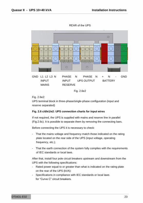
Fig. 2.6e2
Fig. 2.6e2:
UPS terminal block in three-phase/single-phase configuration (input and
reserve separated)
Fig. 2.6 c/d/e1/e2: UPS connection charts for input wires
If not required, the UPS is supplied with mains and reserve line in parallel
(Fig.2.6c). It is possible to separate them by removing the connecting bars.
Before connecting the UPS it is necessary to check:
- That the mains voltage and frequency match those indicated on the rating
plate located on the rear side of the UPS (input voltage, operating
frequency, etc.);
- That the earth connection of the system fully complies with the requirements
of IEC standards or local laws.
After that, install four pole circuit breakers upstream and downstream from the
UPS with the following specifications:
- Rated power equal to or greater than what is indicated on the rating plate
on the rear of the UPS (kVA):
- Specifications in compliance with IEC standards or local laws
for “Curve C” circuit breakers.

Quasar II - UPS 10÷40 kVA Installation Instructions
DT0431-E02 24
2.7 UPS Auxiliary connections
The communication boards are mounted in the rear of the UPS. The standard
equipment is composed of the remote communication board (CS0098) and the
set-up for the SNMP board.
Access to the connections for these two components is located on the rear of
the UPS (Fig. 2.7a).
Remote communication board
(CS0098)
SNMP board
Fig. 2.7a
2.7.1 Remote Communication Board
The remote communication board is used to establish a connection between
the UPS and external devices.
The board has a series of voltage free contact terminals (M1) which can be
connected to a dedicated synoptic panel Chapter 2.7.2), acoustic or visual
warning devices or remote signaling systems.

Quasar II - UPS 10÷40 kVA Installation Instructions
DT0431-E02 25
Battery low
No mains power available Load on reserve
Inverter active
Circuit diagram CS0098
Emergency power off / EPO
One or more remote EPO buttons (Chapter 2.7.4) can be connected via the
other two contacts (CN1).
Finally, it is possible to connect the system to a PC via a DB9 (CN3) connector
and use a special software (Chapter 2.7.3).
Fig. 2.7.1a
Fig. 2.7.1b

Quasar II - UPS 10÷40 kVA Installation Instructions
DT0431-E02 26
2.7.2 Remote Display Panel (optional)
The remote display panel is connected to the UPS via the connection block M1
located on the remote communication board (CS0098) (connection diagram
Fig. 2.7.2b). This device is used for the remote monitoring of the main UPS
blocks, the status of the main blocks is represented through LEDs and there is
also an acoustic alarm, which can be shut off with key 5.
Fig. 2.7.2a
LED description
1) Green LED: UPS On
If on, the UPS is functioning correctly. If off, one or more inverter section
alarms have been activated (acoustic alarm enabled)
2) Yellow LED: BATTERY on
If on, the UPS is functioning in battery mode (acoustic alarm enabled).
3) Red LED: BATTERY low
If on, the battery is almost completely discharged (acoustic alarm enabled).
4) Yellow LED: BYPASS on
If on, the load is supplied from reserve (acoustic alarm enabled)
Quasar II - UPS 10÷40 kVA Installation Instructions
DT0431-E02 27
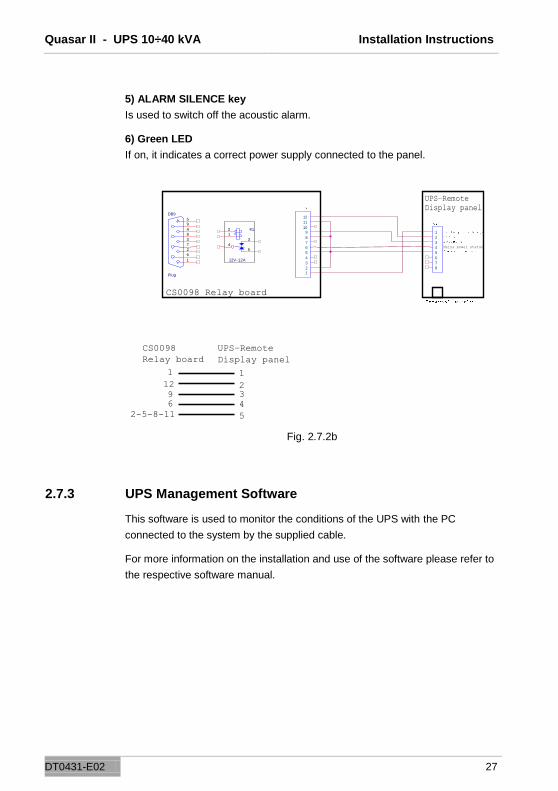
5) ALARM SILENCE key
Is used to switch off the acoustic alarm.
6) Green LED
If on, it indicates a correct power supply connected to the panel.
Fig. 2.7.2b
2.7.3 UPS Management Software
This software is used to monitor the conditions of the UPS with the PC
connected to the system by the supplied cable.
For more information on the installation and use of the software please refer to
the respective software manual.
1 2 3 4 5 6 7 8 9 1 0 1 1 1 2 DB9
Plug
5 9 4 8 3 7 2 6 1
K 1
12V - 1 2 A 4
5 3 1 2 1
2 3 4 5 6 7 8
CS0098 Relay board
UPS–Remote
Display panel
Mains power status
1 2 3 4 5
1
9 6
2-5-8-11
CS0098
Relay board UPS–Remote
Display panel
12
Quasar II - UPS 10÷40 kVA Installation Instructions
DT0431-E02 28
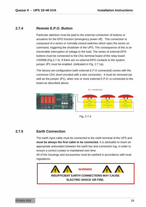
2.7.4 Remote E.P.O. Button
Particular attention must be paid to the external connection of buttons or
actuators for the EPO function (emergency power off). This connection is
composed of a series or normally-closed switches which open the series on
command, triggering the shutdown of the UPS. The consequence of this is an
irreversible interruption of voltage to the load. The series of external EPO
buttons must be connected to the CN1 terminal board of the relay board
CS0098 (Fig.2.7.4). If there are no external EPO contacts to the system,
jumper JP1 must be enabled. (indicated in Fig. 2.7.1a).
The factory-set configuration (with external E.P.O connected) comes with the
connector CN1 short-circuited with a wire connection. It must be removed (as
well as the jumper JP1), when one or more external E.P.O. is connected to the
board as described above.
Fig. 2.7.4
2.7.5 Earth Connection
The earth input cable must be connected to the earth terminal of the UPS and
must be always the first cable to be connected. It is advisable to insert an
appropriate antioxidant between the earth bar and connection lug, in order to
ensure a correct contact is maintained over time.
All of the housings and accessories must be earthed in accordance with local
regulations.
WARNING
INSUFFICIENT EARTH CONNECTIONS MAY CAUSE
ELECTRIC SHOCK OR FIRE.

Quasar II - UPS 10÷40 kVA Control Panel
DT0431-E02 29
3. Control Panel
3.1 Introduction
The control panel is located on the front of the UPS. It is used for a simple
check of the general status of the UPS and batteries and related alarms.
The panel contains an LCD screen (which indicates the operating status,
measured values and UPS alarms) and the red EPO button located top left on
the display. The display panel shows text messages and operating parameters
on an LCD screen with 4 lines and 20 characters per line. The screens are
organized in 6 multi-level menus, which can be selected using the membrane
buttons below the LCD display.
Fig. 3.1
There are two LEDs on the left side of the display: A green one
(“NORMAL“) and a red one (“ALARM“).
The functions of the LEDs are described in table 3.1.
STATUS UPS OK Alarm activated Alarm
acknowledged
GREEN LED On Off On
RED LED Off On Flashing
Table 3.1

Quasar II - UPS 10÷40 kVA Control Panel
DT0431-E02 30
3.2 LCD Control Panel
1 MENU key
To return to the previous menu or to the main menu from the alarm display
2 BACK key
To scroll the options in the menu and submenu. Pressing both at the same
time generates an ENTER command.
3 NEXT key
To scroll the options in the menu and submenu. Pressing both at the same
time generates an ENTER command.
4 ESC key
To switch off the buzzer.
Fig. 3.2
During normal UPS operation the control panel uses a series of messages to
display the operating status of the single component blocks of the system. In
this way, the operator is informed in real time (also with an acoustic signal) of
any faults occurring in the system.

Quasar II - UPS 10÷40 kVA Control Panel
DT0431-E02 31
Table 3.2 shows a list of available menus.
MENU No. DESCRIPTION
UPS STATUS AND ALARMS
1 This is the default setting of the LCD screen. The system returns to this level automatically if no keys are used for 3 minutes.
MEASUREMENTS 2 Used to display all the measured values
UPS COMMANDS 3 Inverter on / off, static switch, battery test
PANEL SETUP 4 Settings for date / time / battery test / language
EVENTS RECORDER MANAGEMENT
5 Displays the log of events and related alarms
SERVICE MODE 6 Reserved for technical service staff
Table 3.2
It is possible to scroll through the menus listed in table 3.2 using the NEXT(>)
or BACK(<) keys.
By pressing the NEXT(>) and BACK(<) keys simultaneously, you select
ENTER (< >) and by confirming the selection go to the next menu level.
To return to the previous menu level press the MENU key.
Each alarm indication on the display is followed by an acoustic signal which
can be switched off by pressing ESC (see Figure 3.2).
If the operator does not perform any actions for 3 minutes, the ―1. UPS
STATUS AND ALARMS‖ menu is automatically displayed.
Quasar II - UPS 10÷40 kVA Control Panel
DT0431-E02 32
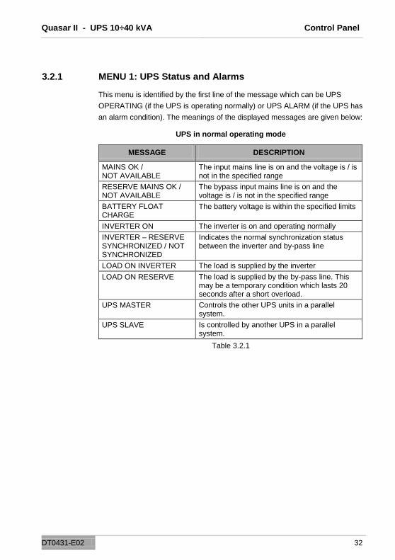
3.2.1 MENU 1: UPS Status and Alarms
This menu is identified by the first line of the message which can be UPS
OPERATING (if the UPS is operating normally) or UPS ALARM (if the UPS has
an alarm condition). The meanings of the displayed messages are given below:
UPS in normal operating mode
MESSAGE DESCRIPTION
MAINS OK / NOT AVAILABLE
The input mains line is on and the voltage is / is not in the specified range
RESERVE MAINS OK / NOT AVAILABLE
The bypass input mains line is on and the voltage is / is not in the specified range
BATTERY FLOAT CHARGE
The battery voltage is within the specified limits
INVERTER ON The inverter is on and operating normally
INVERTER – RESERVE SYNCHRONIZED / NOT SYNCHRONIZED
Indicates the normal synchronization status between the inverter and by-pass line
LOAD ON INVERTER The load is supplied by the inverter
LOAD ON RESERVE The load is supplied by the by-pass line. This may be a temporary condition which lasts 20 seconds after a short overload.
UPS MASTER Controls the other UPS units in a parallel system.
UPS SLAVE Is controlled by another UPS in a parallel system.
Table 3.2.1
Quasar II - UPS 10÷40 kVA Control Panel
DT0431-E02 33
ALARM
CAUSE
UPS ALARM
< BACK or NEXT >
< ENTER >
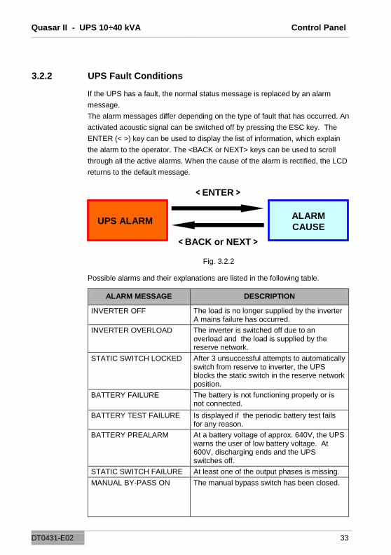
3.2.2 UPS Fault Conditions
If the UPS has a fault, the normal status message is replaced by an alarm
message.
The alarm messages differ depending on the type of fault that has occurred. An
activated acoustic signal can be switched off by pressing the ESC key. The
ENTER (< >) key can be used to display the list of information, which explain
the alarm to the operator. The <BACK or NEXT> keys can be used to scroll
through all the active alarms. When the cause of the alarm is rectified, the LCD
returns to the default message.
Fig. 3.2.2
Possible alarms and their explanations are listed in the following table.
ALARM MESSAGE DESCRIPTION
INVERTER OFF The load is no longer supplied by the inverter A mains failure has occurred.
INVERTER OVERLOAD The inverter is switched off due to an overload and the load is supplied by the reserve network.
STATIC SWITCH LOCKED After 3 unsuccessful attempts to automatically switch from reserve to inverter, the UPS blocks the static switch in the reserve network position.
BATTERY FAILURE
The battery is not functioning properly or is not connected.
BATTERY TEST FAILURE Is displayed if the periodic battery test fails for any reason.
BATTERY PREALARM At a battery voltage of approx. 640V, the UPS warns the user of low battery voltage. At 600V, discharging ends and the UPS switches off.
STATIC SWITCH FAILURE At least one of the output phases is missing.
MANUAL BY-PASS ON The manual bypass switch has been closed.

Quasar II - UPS 10÷40 kVA Control Panel
DT0431-E02 34
ALARM MESSAGE DESCRIPTION
MAINS NOT AVAILABLE The mains is not compatible with the UPS specifications. It might be out of the permissible system range or simply not present.
RESERVE NOT AVAILABLE The reserve is not compatible with the UPS specifications. It might be out of the permissible system range or working in the wrong cyclic direction, or it is not present.
UPS EMERGENCY POWER OFF
Is displayed when the E.P.O. button is pressed for any reason.
BATTERY CHARGER FAILURE
The battery charger is not functioning properly or is not connected.
PARALLEL DATA EXCHANGE FAILURE
This alarm occurs when there is no data exchange between parallel UPS devices for any reason.
This may be due to a missing or incorrect connection of one or more parallel fibers.
Table 3.2.2
3.2.3 MENU 2: Measurements
To access this screen press ENTER on position “2. Measurements‖ on the
main menu. The operator can now check the value of the following electrical
measured values by using the arrows < or >:
V in phase – neutral = Reserve line Y-voltage
V in phase/phase = Reserve line voltage between lines
Input current = UPS input three phase currents
V out phase/neutral = UPS output Y-voltage
Output current = Output current at load
Battery V,I = Battery voltage and current
Frequency = UPS output frequency
Temperature = Temperature of the power stage, input stage,
output stage and housing
Temperature = Temperature of the external battery housing in
order to regulate the battery voltage according to
the measured value.
If no operation is performed for 3 minutes, the ―1. UPS STATUS AND
ALARMS‖ menu is displayed again.

Quasar II - UPS 10÷40 kVA Control Panel
DT0431-E02 35
3.2.4 MENU 3: UPS Commands
The UPS can be controlled through this menu.
MESSAGE DESCRIPTION
3.1 INVERTER ON
3.2 INVERTER OFF
When this message is displayed, the user can switch the inverter on or off permanently by pressing ENTER. The inverter must be switched on at the start and after the switch-off following the permanent overload.
3.3 SWITCH LOAD
TO INVERTER
When this message is displayed, the load is switched from the reserve line to the inverter when ENTER is pressed.
3.4 SWITCH LOAD
TO RESERVE
When this message is displayed, the load is switched from the inverter to the reserve line when ENTER is pressed.
3.5 START BATTERY
TEST
When this message is displayed, an automatic battery test is started upon pressing ENTER. The test lasts for about 30 seconds.
Table 3.2.4
If no operation is performed for 3 minutes, the ―1. UPS STATUS AND
ALARMS‖ menu is displayed again.
3.2.5 MENU 4: Panel Setup
MESSAGE DESCRIPTION
4.1 DATE SETTING Sets the current date. Use the arrow keys to increase/decrease the numbers.
4.2 TIME SETTING Sets the current time. Use the arrow keys to increase/decrease the numbers.
4.3 PANEL LANGUAGE SETTING
Used to select the display languages (from the available preinstalled languages)
4.4 ALARMS SETUP Allows the user to define whether a recorded alarm is hidden or displayed until the ESC key is pressed.
4.5 BATTERY TEST SETTING
Used to set the periodic battery test by selecting the day of the week, the number of weeks between the tests and the time of day to start the test.
Table 3.2.5
If no operation is performed for 3 minutes, the ―1. UPS STATUS AND
ALARMS‖ menu is displayed again.

Quasar II - UPS 10÷40 kVA Control Panel
DT0431-E02 36
3.2.6 MENU 5: Event Log Management
In this menu the user can see last 1024 events / alarms in chronological order.
The event log display can be opened by selecting 5. EVENT LOG in the main
menu and then choosing the DISPLAY LOG command. The screen shows the
date and time of the last event that occurred.
It is possible to scroll through the list using the <BACK or NEXT> keys.
Pressing MENU at any position on the event list returns you to the MAIN
MENU.
To delete all the events select DELETE EVENTS from the submenu and
then press <ENTER>.
If no operation is performed for 3 minutes, the ―1. UPS STATUS AND
ALARMS‖ menu is displayed again.
3.2.7 MENU 6: SERVICE MODE
Through this menu the user can change UPS related data, reset the EPO,
request the software and hardware version, etc. This menu is password-
protected to prevent unauthorized access.
If no operation is performed for 3 minutes, the ―1. UPS STATUS AND
ALARMS‖ menu is displayed again.

Quasar II - UPS 10÷40 kVA Instructions for Using the UPS
DT0431-E02 37
4. Instructions for Using the UPS
IMPORTANT
Please follow the procedures described below carefully to avoid damage to the
system.
ATTENTION
The UPS cannot be started from the battery.
!

Quasar II - UPS 10÷40 kVA Instructions for Using the UPS
DT0431-E02 38
4.1 Introduction
This Chapter describes the correct use of the system.
The UPS may be in one of the following operating modes:
Normal mode - The load is supplied by the UPS. The UPS is in normal operation and uses mains power to supply energy to the load and charge the batteries. This mode guarantees that complete, uninterrupted power is supplied to the load. Operation with internal automatic by-pass – The load is supplied by mains power In the event of an inverter fault and/or overload, the power to the load is provided by the reserve line. This mode does not guarantee that complete, uninterrupted power is supplied to the load.
Operation with maintenance manual by-pass enabled – The UPS is disabled. The load is connected directly to the mains through the maintenance or emergency manual by-pass line. This mode does not guarantee that complete, uninterrupted power is supplied to the load.
Battery mode - The load is supplied by the UPS. The UPS is in normal operation mode and uses the battery to supply energy to the load because the mains voltage is out of the allowed range This mode guarantees that complete, uninterrupted power is supplied to the load.

Quasar II - UPS 10÷40 kVA Instructions for Using the UPS
DT0431-E02 39
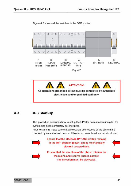
4.2 Power Switches
The system maintenance elements are located behind the front doors, installed
horizontally and the following describes them in order from left to right side (see
Fig. 4.2):
MAINS INPUT SWITCH (I1): Connects the UPS to the mains voltage.
RESERVE INPUT SWITCH (I2): Connects the UPS to the reserve line voltage.
MANUAL BYPASS SWITCH (I3): Allows the disconnection of the entire UPS
and the provision of mains supply to the load. This switch is protected with a
small padlock to avoid accidental use.
UPS-OUTPUT SWITCH (l4): Connects the UPS to the load.
The UPS switches were described above. There are also battery breakers
inside the battery module and in every external battery module.
To completely isolate the unit from hazardous voltages it is necessary to
open the battery switch as well, which is not located on the UPS.
Also, the presence of potentially charged capacitors inside the converter
should be considered. This means that you must wait for at least 10 min.
before accessing the internal parts of the UPS.
Follow the steps below to correctly switch on the UPS.
ATTENTION!
SWITCH IN DOWN POSITION MEANS THAT THE CIRCUIT IS OPEN
SWITCH IN UP POSITION MEANS THAT THE CIRCUIT IS CLOSED
Quasar II - UPS 10÷40 kVA Instructions for Using the UPS
DT0431-E02 40
I1 INPUT MAINS
I2INPUT
RESERVE
I3MANUAL BY-PASS
I4OUTPUT
UPS
I5BATTERY
I6 NEUTRAL
Figure 4.2 shows all the switches in the OFF position.
Fig. 4.2
ATTENTION!
All operations described below must be completed by authorized
electricians and/or qualified staff only.
4.3 UPS Start-Up
This procedure describes how to setup the UPS for normal operation after the
system has been completely de-energized.
Prior to starting, make sure that all electrical connections of the system are
checked by an authorized person. All external power breakers remain closed.
Ensure that the MANUAL BYPASS switch remains
in the OFF position (down) and is mechanically
blocked by a padlock.
Ensure that the direction of the phase rotation for
the mains and reserve lines is correct.
The direction must be clockwise.

Quasar II - UPS 10÷40 kVA Instructions for Using the UPS
DT0431-E02 41
For an explanation of the switches refer to fig. 4.2.
Once all the points above have been verified, proceed following the steps
below.
1. Close the INPUT RESERVE (l2) switch.
The LCD panel and all UPS logic boards begin normal operation.
If the reserve line voltage parameters are correct, the UPS fans switch on.
2. Close the UPS OUTPUT (l4) switch
The load connected to the UPS output is supplied with the power
provided by the reserve line.
3. Close the MAINS INPUT (l1) switch
Wait for about 10 seconds. In this time a progressive capacitors pre-charge
process is initiated, which protects the mains from overload.
The INVERTER OFF message appears on the LCD.
4. Switch on the inverter
Using menu 3. UPS COMMANDS, select Inverter ON and press
ENTER. This activates the inverter.
5. Verify the UPS operating status
Wait for about 30 seconds. After this the static switch should automatically
switch the load from the reserve line to the inverter.
Check the correct operating status, indicated by the green
LED on the control panel.
6. Battery connection
After checking the correct polarity of the batteries close the interior battery
panel switch This makes the connection between the batteries and the UPS
circuits.
At this point the unit is in normal operating mode, and guarantees uninterrupted
power supply to the load.
It is recommended that you simulate a short power failure to check the correct
operation of the entire UPS / battery system. To perform this operation just
open and then close the mains switch powering the UPS.

Quasar II - UPS 10÷40 kVA Instructions for Using the UPS
DT0431-E02 42
4.4 Instructions for Switching the System to Manual
Bypass Mode
If for maintenance purposes or other reasons the UPS has to be separated
from the system, while at the same time mains power has to be supplied to the
critical load, proceed as follows:
1. Select menu 3. UPS COMMANDS
Select the item Transfer load to reserve network and press ENTER From
this moment the load is supplied directly from the reserve network.
2. Switch off the inverter
Using menu 3. UPS COMMANDS select Inverter ON/OFF and press
ENTER. This turns off the inverter and uninterrupted
supply to the load is no longer guaranteed.
3. Close MANUAL BY-PASS (I3) switch
Remove the padlock (or any other mechanical
safety lock) from the switch and lift the knob
to the ON position.
4. Open the INPUT MAINS (I1) switch
5. Open the INPUT RESERVE (l2) switch.
The load is supplied directly from the mains through the manual By-Pass.
6. Open the UPS OUTPUT (l4) switch
7. Disconnect the battery
8. Open the NEUTRAL (I6) switch (only
if there is work to be done on the module
Attention
Hazardous voltage may still be present inside the UPS
Please contact the manufacturer.

Quasar II - UPS 10÷40 kVA Instructions for Using the UPS
DT0431-E02 43
4.5 Instructions for Return from Manual Bypass Mode to
Normal Mode
To return to normal operation from the manual bypass mode, proceed as
follows:
1. Close the INPUT RESERVE (l2) switch.
At this point, if the supply of the reserve line is present and within allowed
range, the LCD display will switch on and also all UPS circuits will initiate
their operations. The fan starts working.
2. Close the UPS OUTPUT (l4) switch
3. Open the MANUAL BY-PASS (I3) switch
At this point the load is supplied from the reserve line.
Hang the padlock on the manual by-pass switch (l3) again.
4. Close the INPUT MAINS (l1) switch
Wait for about 10 seconds. During this time, the progressive capacitors pre-
charge process is initiated, which protects the mains from overload.
The INVERTER OFF message appears on the LCD.
5. Switch on the inverter
Using menu 3. UPS COMMANDS select Inverter ON/OFF and press
ENTER
6. Verify the UPS operating status
Wait about 30 seconds. After this the static switch automatically switches
the load from the reserve line to the inverter.
Check the correct operating status, indicated by the green LED on the panel
display.
7. Battery connection
After checking the correct polarity of the batteries close the interior battery
panel switch. It makes the connection between the batteries and the UPS
circuits.

Quasar II - UPS 10÷40 kVA Instructions for Using the UPS
DT0431-E02 44
4.6 Instructions for a Complete UPS Shutdown
If for maintenance purposes or other reasons the UPS has to be switched off
and the load is no longer supplied, proceed as follows:
1. Select menu 3. UPS COMMANDS
Select the item Transfer load to reserve network and press ENTER
From this moment the load is supplied directly from the reserve network.
2. Switch off the inverter
Using menu 3. UPS COMMANDS select Inverter ON/OFF and press
ENTER.
This turns off the inverter and uninterrupted supply is no longer guaranteed
to the load.
3. Open UPS OUTPUT (I4) switch
The load is not supplied with power.
4. Open the INPUT RESERVE (l2) switch.
5. Open the INPUT MAINS (I1) switch
6. Disconnect the battery
7. Open the NEUTRAL (I6) switch (only if work has to be done on the
module)
Attention
Hazardous voltage may still be present inside the UPS
Please contact the manufacturer.

Quasar II - UPS 10÷40 kVA Instructions for Using the UPS
DT0431-E02 45
4.7 E.P.O. (Emergency Power Off)
The purpose of the emergency power off is to shut down the UPS completely, if
required. This also includes the immediate switching off of the static switch
from both reserve and inverter sources. This eliminates any power at the UPS
output and – as a result - at the load.
Obviously, hazardous voltages remain inside the UPS panel.
To reset EPO mode, the complete UPS shut down procedure has to be
executed.
4.8 Instructions to Start the UPS from Power Save Mode
This procedure must be followed to start the UPS from a completely de-
energized state.
Prior to starting, make sure that all electrical connections of the system are
checked by an authorized person. All external power breakers remain closed.
Ensure that the MANUAL BYPASS switch
remains in the OFF position (down) and is
mechanically blocked by a padlock.
Ensure that the direction of the phase rotation
for the mains and reserve lines is correct.
The direction must be clockwise.

Quasar II - UPS 10÷40 kVA Instructions for Using the UPS
DT0431-E02 46
For an explanation of the switches refer to fig. 4.2.
Once all the points above have been verified, proceed following the steps
below.
1. Close the INPUT RESERVE (l2) switch
The LCD panel and all UPS logic boards begin normal operation.
If the reserve line voltage parameters are correct, the UPS fans switch on.
2. Close the UPS OUTPUT (l4) switch
The load connected to the UPS output is supplied with power.
3. Close the INPUT MAINS (l1) switch
Wait for about 10 seconds. During this time, the progressive capacitors pre-
charge process is initiated, which protects the mains from overload.
The INVERTER OFF message appears on the LCD.
4. Switch on the inverter
Using menu 3. UPS COMMANDS select Inverter ON/OFF and press
ENTER.
Check the correct operating status, indicated by the green LED on the panel
display.
5. Battery connection
After checking the correct polarity of the batteries close the interior battery
panel switch. It makes the connection between the batteries and the UPS
circuits.
At this point the unit is in normal operating mode, and guarantees uninterrupted
power supply to the load.
It is recommended that you simulate a short power failure to check the correct
operation of the entire UPS / battery system. To perform this operation just
open and then close the mains switch powering the UPS.
Quasar II - UPS 10÷40 kVA Instructions for Using the UPS
DT0431-E02 47
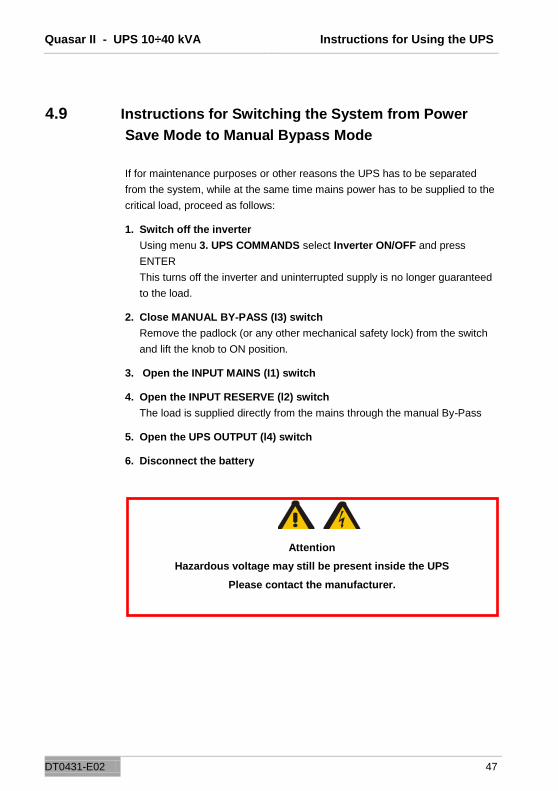
4.9 Instructions for Switching the System from Power
Save Mode to Manual Bypass Mode
If for maintenance purposes or other reasons the UPS has to be separated
from the system, while at the same time mains power has to be supplied to the
critical load, proceed as follows:
1. Switch off the inverter
Using menu 3. UPS COMMANDS select Inverter ON/OFF and press
ENTER
This turns off the inverter and uninterrupted supply is no longer guaranteed
to the load.
2. Close MANUAL BY-PASS (I3) switch
Remove the padlock (or any other mechanical safety lock) from the switch
and lift the knob to ON position.
3. Open the INPUT MAINS (I1) switch
4. Open the INPUT RESERVE (l2) switch
The load is supplied directly from the mains through the manual By-Pass
5. Open the UPS OUTPUT (l4) switch
6. Disconnect the battery
Attention
Hazardous voltage may still be present inside the UPS
Please contact the manufacturer.

Quasar II - UPS 10÷40 kVA Instructions for Using the UPS
DT0431-E02 48
4.10 Instructions for Return from Manual Bypass Mode to
Normal Mode in Power Save Mode.
To return to normal operation from the manual bypass mode, proceed as
follows:
1. Close the INPUT RESERVE (l2) switch
At this point, if the supply of the reserve line is present and within allowed
range, the LCD display switches on, all UPS circuits initiate their operations
and the fan switches on.
2. Close the UPS OUTPUT (l4) switch
3. Open MANUAL BY-PASS (l3) switch
At this point the load is supplied from the reserve line.
Hang the padlock on the manual by-pass switch (l3) again.
4. Close the INPUT MAINS (l1) switch
Wait for about 10 seconds During this time, the progressive capacitors pre-
charge process is initiated, which protects the mains from overload.
The INVERTER OFF message appears on the LCD.
5. Switch on the inverter
Using menu 3. UPS COMMANDS select Inverter ON/OFF and press
ENTER.
Check the correct operating status, indicated by the green LED on the panel
display
6. Battery connection
After checking the correct polarity of the batteries close the interior battery
panel switch. It makes the connection between the batteries and the UPS
circuits.

Quasar II - UPS 10÷40 kVA Instructions for Using the UPS
DT0431-E02 49
4.11 Instructions for the Complete Shutdown of the UPS in
Power Save Mode
If for maintenance or other reasons the system should be completely shut
down without supplying any power to the consumer loads, proceed as follows:
1. Switch off the inverter
Using menu 3. UPS COMMANDS select Inverter ON/OFF and press
ENTER.
This turns off the inverter and the uninterrupted supply is no longer
guaranteed to the consumer loads.
2. Open LOAD l3 circuit breaker
In this situation the consumer loads are not supplied.
3. Open the INPUT RESERVE (l2) circuit breaker.
4. Open the MAINS (l2) circuit breaker.
5. Disconnect the battery
6. Open the NEUTRAL (I6) switch (only if work has to be done on the
module)
Attention
Hazardous voltage may still be present inside the UPS
Please contact the manufacturer.
Quasar II - UPS 10÷40 kVA Instructions for Using the UPS
DT0431-E02 50
4.12 Managing the UPS Battery
In addition to the battery voltage and current measurements, displayed in
menu ―2. MEASUREMENTS‖, it is also possible to test the battery power
without any interruption to the load supply.
In case of battery failure, the message ―BATTERY TEST FAILED” is
displayed on the LCD.
Contact the technical support staff in this case.
4.12.1 Battery Test Programming
The battery test can be executed at any time by selecting the menu ―3. UPS
COMMANDS” and pressing ENTER on “BATTERY TEST” command The test
lasts for about 30 seconds.
It is also possible to schedule a periodic battery test following the instructions
below:
1. Select the “4. PANEL SETUP” menu and press ENTER
2. Select “BATTERY TEST SETTING” and press ENTER
Using the arrows, select the day of the week to perform the test, the number of
weeks between tests (from 1 to 99, 0 means no automatic test) and the time of
the day to start the test.
Press ENTER to confirm your selection.

Quasar II - UPS 10÷40 kVA UPS Devices in Parallel
DT0431-E02 51
5. UPS Devices in Parallel
5.1 System Set-up
The installation of many UPS in parallel requires creating one or more panels
of the individual UPSs. The type of panel created guarantees different levels of
operation, depending on the complexity of the chosen solution. The typical,
normally suggested solution is described below, which guarantees complete
operation of the system. (fig.5.1) Separators are included on all the power lines
of the individual groups, to disconnect their return line and to protect the
batteries. Moreover, it is advisable to set-up a general by-pass for the system.
For this purpose, we recommend the implementation of a functional
interlocking device. This interlocking device is necessary to prevent damage to
the system The solutions shown here permit all the test functions during the
installation and maintenance phases of the individual groups The general
manual by-pass can be used to isolate the entire system without load supply
interruptions.
Fig. 5.1
The complexity of the system requires a suitable monitoring of the status of
each UPS by remote or SNMP see Chapter 1.2.4)
For additional information, see the attached technical report DT0367.
(only for parallel systems)
Quasar II - UPS 10÷40 kVA Troubleshooting
DT0431-E02 52
6. Troubleshooting
6.1 General Alarms
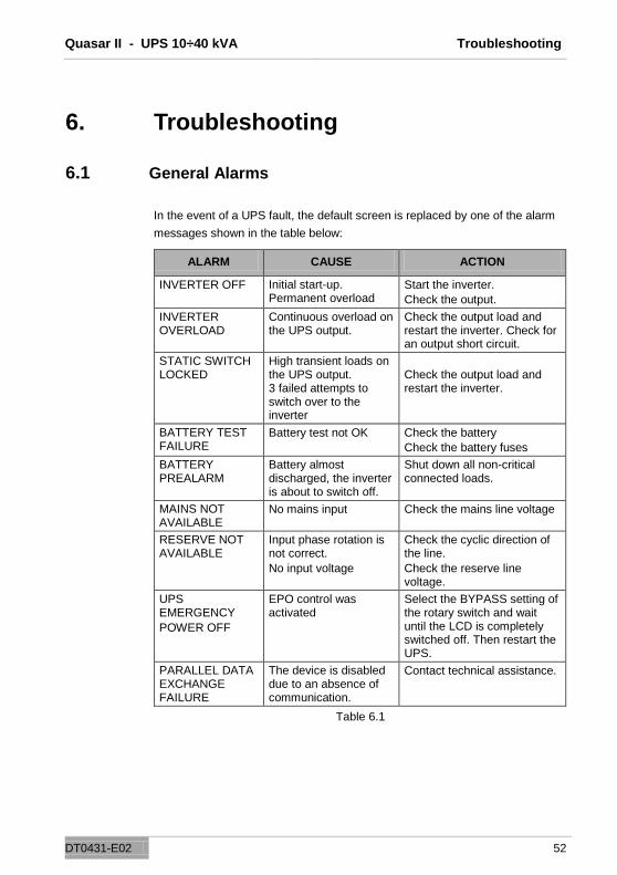
In the event of a UPS fault, the default screen is replaced by one of the alarm
messages shown in the table below:
ALARM CAUSE ACTION
INVERTER OFF Initial start-up. Permanent overload
Start the inverter.
Check the output.
INVERTER OVERLOAD
Continuous overload on the UPS output.
Check the output load and restart the inverter. Check for an output short circuit.
STATIC SWITCH LOCKED
High transient loads on the UPS output. 3 failed attempts to switch over to the inverter
Check the output load and restart the inverter.
BATTERY TEST FAILURE
Battery test not OK Check the battery
Check the battery fuses
BATTERY PREALARM
Battery almost discharged, the inverter is about to switch off.
Shut down all non-critical connected loads.
MAINS NOT AVAILABLE
No mains input Check the mains line voltage
RESERVE NOT AVAILABLE
Input phase rotation is not correct.
No input voltage
Check the cyclic direction of the line.
Check the reserve line voltage.
UPS EMERGENCY
POWER OFF
EPO control was activated
Select the BYPASS setting of the rotary switch and wait until the LCD is completely switched off. Then restart the UPS.
PARALLEL DATA EXCHANGE FAILURE
The device is disabled due to an absence of communication.
Contact technical assistance.
Table 6.1

Quasar II - UPS 10÷40 kVA Troubleshooting
DT0431-E02 53
If a UPS experiences a fault that cannot be resolved and it is not able to
guarantee uninterrupted power to the load, perform an EMERGENCY BY-
PASS and then leave the machine isolated and switched off. Contact
technical assistance.
6.2 In Case of Fire
In the very unlikely event of a fire, only CO2 or powder extinguishers should
be used. Always trigger the emergency BY-PASS. Then, shut down the
machine completely and disconnect the battery panel.
6.3 Faults Due to Load Disorder
Often, normal UPS reactions to non-standard loads or installation environment
conditions are incorrectly identified by users as UPS faults.
The most common situations are:
The UPS supplies the load through the reserve line even if the inverter
section is operating correctly: This may occur in the case of excessive
absorbed peak current. It causes a major voltage drop, which, if it is
repeated, leads to the switching of the load to the reserve line.
If the system has made three failed attempts to switch over to the inverter
and back, the static switch on the reserve line is blocked, in order to
protect the inverter, Therefore it is necessary to investigate the load
current and eliminate the causes of such current peaks.
The repeated peak current should not exceed 2.5 times the effective
value.
The accuracy of the UPS output voltage is not optimal. This may depend
on an excessively asymmetrical and/or distorted load.

Quasar II - UPS 10÷40 kVA Scheduled Maintenance
DT0431-E02 54
7. Scheduled Maintenance
During its lifetime, the UPS requires scheduled maintenance cycles to
maintain operating reliability and efficiency.
Scheduled maintenance must be performed by the company which supplied
the machine or by a company specialized and trained on the system by the
seller.
7.1 Note
The EFFEKTA UPS is a technically mature and proven system that provides a
high degree of safety. Due to its modern construction, the careful selection of
materials, state-of-the-art production technology and conscientious work done
by committed staff, EFFEKTA UPS has all the typical characteristics such as
efficiency, reliability and long-term quality.
As we are convinced that your UPS is a quality device, we offer you:
a 24 month warranty, free from faults.
Thanks to its modern technology, the UPS needs very little maintenance.
Usually, only one inspection needs to be done per year. This is important for
any warranty claim!
You will certainly be pleased to know that an efficient service organization is at
the ready to take care of your UPS system.
The service plan includes:
– The most important characteristics of your UPS system
– Any work necessary during inspection
The service plan handbook is used to confirm any work completed (important
for warranty claims).
In the case of faults in your UPS system, please call the following telephone
number:
– On working days from 8.00 AM to 5.00 PM +49 (0)741 1745152
+49 (0)741 174510
– From 5.00 PM to 8.00 AM, on weekends and on holidays, we are
available if previously agreed.