Embed Size (px)
Citation preview

http://ammtiac.alionscience.com/quarterly
http://ammtiac.alionscience.com/quarterly

http://ammtiac.alionscience.com The AMMTIAC Quarterly, Volume 3, Number 3 3
ABSTRACTTitanium dioxide or titania (TiO2) has well-known photoactiveantimicrobial attributes. It also readily forms on titaniumimplants. Recently conducted in vitro studies have demonstratedincreased osteoblast functions of nanostructured TiO2 necessaryto promote the efficacy of orthopedic implants. Titania-basedceramics (bulk material, thin films, nanoscale powders, etc.) aregenerally synthesized by using either a highly corrosive andtoxic titanium tetrachloride (TiCl4) and titanium oxychloride(TiOCl2) or rather expensive and moisture-sensitive titaniumisopropoxide [Ti(C3H7O)4] as the starting chemicals. In thispaper, the technique of electrospinning has been used to fabricatenon-woven, breathable titania nanomats† employing titanylnitrate as a benign and inexpensive precursor.
INTRODUCTIONTitanium dioxide (also known as rutile) in pure or doped formhas been extensively used in a number of applications, rangingfrom food coloring, paints, cosmetics, catalysts, anti-biofouling,photovoltaic solar cells, and sunscreens to gas sensors. In addi-tion, due to its suitable energy band gap (≈ 3.2 -3.5 electron volts,eV), titania has also gained interest in photonic band gap crystalsfor the visible spectrum of light due to its high refractive index(nrutile ≈ 2.9) and low absorption properties [1]. Recently, self-cleaning wool-polyamide, polyester and cotton textiles coatedwith TiO2 have been also reported [2-7]. One of the unique phys-ical properties of titania is its photocatalysis – a photo-activated antimicrobial/disinfective activity where free radicalsgenerated from TiO2 oxidize organic matter upon activation bylight. This property makes the material a candidate for numerousmedical applications where infection control is needed. By inter-posing an effective procedure based on nanotechnology, the bonehealing can be made safer and to take place at an acceleratedpace, simultaneously eliminating or mitigating the probability ofwound infection. However, the unique photocatalytic propertyof nanostructured titania as a wound and bone fracture disinfec-tant has not been exploited hitherto. Constructing non-woven
TiO2 nanothreads and nanomats possessing a three-dimensionalscaffold structure and optimal porosity, in conjunction withphoto-activated antimicrobial activity, could provide a significantimprovement in the management of segmental bone defectsparticularly in the presence of infection. A photoactive TiO2nanomat either in pristine form or impregnated with antibacteri-al agents can be used as an effective ultralight disinfectant gauzefor wound healing upon brief activation by light.Considering that the natural scaffold (extracellular matrix or
ECM) consists of a multilayered fibrous and porous architecture,the possibility of utilizing electrospinning as a novel nanomanu-facturing technique applicable to tissue engineering has emerged.Several researchers have explored the feasibility of fabricating bio-threads containing live cells in benign polymeric matrices thatcould be used for a number of applications including woundhealing and tissue growth. Electrospun fibers are found to possessfeatures that bear morphologic similarity to the ECM of naturaltissue such as high porosity and effective mechanical properties.They therefore meet the essential design criteria of an ideallyengineered scaffold [8-9]. Recently, the authors have successful-ly carried out preliminary experiments to attach cells to theelectrospun polymeric (poly vinyl pyrrolidone or PVP) as well asceramic (alumina) nanofibers [10].With the goal of using nanomats to combat wound infection
due to its photoactive attributes, this paper describes the fabrica-tion and characterization of non-woven titania nanofibers using asimpler and more benign precursor than that which has usuallybeen used in the case of titania synthesis. In this case, an aqueoustitanyl nitrate (TiO(NO3)2) was synthesized from watersoluble titanium fluoride, as described in the ExperimentalProcedure section. First, an appropriate ceramic-polymer (ceramer)composite of titania electrospun as a continuous non-wovennanofibrillar mat was fabricated from an optimizedmixture of suitable inorganic and polymeric precursor blend.The ceramer composite was then processed carefully and the trans-formation of ceramer to high purity, crystallized and morphologi-cally optimized titania was followed by a well-conceived heat-
Abdul-Majeed Azad*Sara Lynne McKelvey
The University of ToledoToledo, OH
Zainab Al-FirdausPerrysburg High School
Perrysburg, OH
http://ammtiac.alionscience.com/quarterly
http://ammtiac.alionscience.com/quarterly

The AMMTIAC Quarterly, Volume 3, Number 34
treatment and the systematic phase evolution. The structural andmorphological features of the products, subsequent to each of suchheat-treatments, were verified by X-ray diffraction (XRD), scan-ning electron microscopy (SEM), and transmission electronmicroscopy (TEM) coupled with energy dispersive spectroscopyand selected area electron diffraction (EDS–SAED) techniques.The photoactive efficacy of these electrospun titania nanofibers iscurrently under investigation and will be reported separately.
EXPERIMENTAL PROCEDUREGranular polyvinyl pyrrolidone (PVP, average molecular weight~1.3×10⁶) was used as the polymeric component of the inorgan-ic-organic composite. A 15 wt.% PVP solution was made by dis-solving PVP powder in reagent grade ethanol under constant andvigorous stirring. Due to the pronounced volatility of ethanolduring and after the preparation and the tendency of the solutionto dry out and leave a stiff gel in the container upon prolongedstorage, the PVP solution was prepared in small batches and onlywhen electrospinning was to be carried out. The inorganic pre-cursor used for electrospinning the ceramer composite of titaniawas made from titanium (IV) fluoride (TiF4, purity 98%). In atypical batch preparation, 1.3254 g of titanium tetrafluoride wasdissolved by adding to 50 ml of deionized (DI) water in smallincrements over a period of 90 minutes under constant stirringand gentle heating until it dissolved completely giving a cleartransparent solution of 0.214 M strength. The resulting solutionwas diluted with 230 ml of DI water, to which 20 ml of 7.4 Mammonium hydroxide (NH4OH) was added slowly under con-stant stirring. A white precipitate of titanium hydroxide(Ti(OH)4) was formed and was allowed to settle for 2 hours.The supernatant liquid was tested by adding a few drops ofammonium hydroxide. Absence of the formation of freshprecipitate indicated that the reaction was complete.The Ti(OH)4 suspension was allowed to settle overnight and
tested again for additional precipitation the next day. The super-natant liquid was decanted, and the precipitate was washed withDI water and centrifuged several times until the decanted liquidacquired a near neutral pH (~8). Fifteen milliliters of concentrat-ed nitric acid (HNO3) was added to the hydrated solidTi(OH)4[TiO2·xH2O] under constant stirring, until the precipi-tate began to dissolve. Ten milliliters of HNO3 was added againafter 30 minutes and the precipitate promptly began to dissolve.Subsequently, every 25 minutes additional HNO3 was added indecreasing volume increments (5 ml, 3 ml, and 2 ml, bringing thetotal amount of concentrated nitric acid to 40 ml) to completelydissolve the hydrated titanium hydroxide and to form titanylnitrate (TiO(NO3)2, TN), which is a clear solution with a distinc-tive luster. It is worth noting that the titanyl nitrate solution isrelatively unstable over long periods and tends to become cloudyand to re-form hydrated titania. Therefore, the precursor was syn-thesized only when needed and was used soon after preparation.In order to optimize the electrospinning conditions, the pre-
cursor solutions (TN and PVP) were mixed in different volume/volume (v/v) ratios and stirred into homogeneous viscous solu-tions. Each of these mixtures (1:1, 1:2 and 2:3 v/v) was drawninto a 10 ml capacity clinical syringe. A precision-tip 25-gaugestainless steel needle was attached to the syringe, which wasmounted on a programmable syringe pump. The preferredorientation of the syringe pump in this work was horizontal. A
custom-made direct current power supply with a high voltagesystem (30 kV maximum) using a modified version of a circuitdesign developed at NASA Glenn Research Center [11] was usedfor electrospinning (e-spinning). One terminal of the powersupply was connected to the needle, while the other was connect-ed to a grounded stainless steel collector plate.However, for the ease of sample handling and subsequent
thermal processing, ceramic plates instead of metal were used as acollector. In order to enhance the fiber collection area, a modifiedcollection set-up was devised. Two (4.5 in. × 4.5 in.) dense alumi-na plates (0.0625 in. thick) were employed. The plates were kepta half inch apart and connected together to a common junctionby attaching short lengths of electrical wires to the center of eachplate through blocks of one square inch of aluminum foil stuck tothe back of the plates with double-sided tape. This allowed thefibers to spread and collect across the plates and including theempty space between them. Other details of this set-up aredescribed elsewhere [12-13].Using the high-voltage power supply, an electrical impulse was
applied between the needle and the collectors in order to initiatethe e-spinning. After the voltage was turned on, the syringe pumpwas started. The voltage was tweaked precisely until the fibersbegan to form steadily and collect on the plate, placed threeinches away from the tip of the needle; the optimized voltagein this case was found to be 16 kV. A flow rate of 0.02 ml/h waschosen, and the ceramer fibers were spun continuously with shortintermittent interruptions of the run for periodic cleaning of theclogged needle tip.After spinning was complete, small amounts of the as-spun
composite fibers were used for characterization by scanning elec-tron microscopy. This exercise allowed the determination ofwhich mixture of the two precursors was the more optimal interms of the quality of the fibers (free from intertwining, twisting,branching, liquid globule entrapment, etc.). The remaining fiberscollected on the ceramic plates were fired at 700°C for one hourin static air as per the following heating rate-temperature-soaktime profile: 22°C (room temperature) to 500°C at a rate of½ °C/min. with a hold at 500°C for one hour; 500°C to 700°Cat a rate of ½ °C/min. with a hold at 700°C for one hour,followed by cooling from 700°C to the room temperature at arate of 1 °C/min. The rather small heating and cooling rates werechosen so as to ensure the removal of organic components with-out destroying the nanofibrillar morphological features in the endproduct and also to avoid the disintegration of the titaniananofibers into powdery grains. Subsequent to cooling, the sam-ples were collected for characterization by a host of analyticaltechniques, such as X-ray diffraction, scanning and transmissionelectron microscopy, energy dispersive spectroscopy and selectedarea electron diffraction. The results of photoactivity evaluationand biocidal efficacy of the electrospun titania nanofibers will bereported subsequently.
RESULTS AND DISCUSSIONHollow titania fibers have been prepared by soaking the electro-spun poly (lactic acid) in a 1:19 (v/v) solution of titanium (IV)isopropoxide and isopropanol, followed by hydrolysis, vacuumdrying and calcination at 450°C for ten hours at a ramp rate of15 °C/min., three hours of which were in a nitrogen atmosphereand seven hours in an oxygen atmosphere. [14] The amorphous
http://ammtiac.alionscience.com/quarterly
http://ammtiac.alionscience.com/quarterly
http://ammtiac.alionscience.com The AMMTIAC Quarterly, Volume 3, Number 3 5
titania fibers were shown to be porous and500 nm across. As is evident, the techniqueinvolves several time-consuming processes:electrospinning of the polymeric skeletonfirst; preparing of inorganic sol, followed bygel formation and its hydrolysis onto theelectrospun polymeric fibers before theorganics are removed to yield the desiredceramic nanofibers. Moreover, the authorsof reference 14 claim that the surface of thefiber is not flat but contains small ovalindentations, which are due to rapid phaseseparation during the electrospinningprocess, where the solvent-rich regionsresult in pore formation. This statement,equivalent to the postulation of the exis-tence of a ‘concentration gradient’ region inthe dynamic process of fiber formation, israther speculative and unsubstantiated; thisis particularly so, in the light of the absenceof any visible ‘thinning’ along the fiberlength. If this were true, some collapsingand narrowing of the uniform tubes toform ‘sheets’ should certainly be observedin the high magnification micrographsincluded in the reference.A similar procedure has also been adopt-
ed to synthesize metal (tin and titanium)oxide coated polymer nanofibers with adiameter on the order of 100 nm and acoating thickness ranging from 20 to 80nm. [15] The preparatory technique used isalso quite elaborate and involved. It usescomplex salts, such as ammonium hexa-fluorotitanate and ammonium hexafluoro-stannate, as the precursors and requires ahalide scavenger in the form of boric acid.Furthermore, as seen from the SEMimages, the metal oxide coating is unevenand non-uniform, and the TEM imagesconfirm this. Other researchers have used asol of titanium and silicon to electrospin sil-ica-doped titania nanofibers onto a rotatingdrum. [16] The ceramic fibers wereobtained by firing them for two hours inthe temperature range of 500-1000°C.However, while the SEM images of the as-spun fibers and those dried (incorrectlyreferred to as ‘calcined’ in the reference) at100°C for two hours alone are shown, nomicrographs of the fired samples wereincluded. Hence, the morphological fea-tures of the samples calcined in the range500-1000°C is unknown.The fabrication of anatase titania porous
nanofibers of controlled diameter using anethanol solution containing both PVP andtitanium (IV) isopropoxide via electrospin-ning, followed by calcination in air at
500°C, has been reported. [17] Thisresearch shows that the average fiber diam-eter ranged between 20 and 200 nmdepending upon a number of parameters,such as the strength and ratio of PVP andtitanium (IV) isopropoxide solutions, thestrength of the applied electric field, andthe flow rate of the precursor solution.
As can clearly be seen from above, thesynthesis of pure and/or doped titaniananofibers via electrospinning: (a) involveselaborate routes, or (b) uses either a com-plex compound (ammonium fluoroti-tanate, for example) in combination with ahalide scavenger, or a relatively expensiveand moisture-sensitive titanium (IV) iso-propoxide, as a precursor. Moreover, a tech-nique of coating an electrospun polymericskeleton with titania precursor followed bycalcination does not produce the as-desireduniform and homogeneous ceramic fibers.In contrast, the present work describes theprocedure of synthesizing a simple titaniumprecursor (viz., titanyl nitrate) from a lessreactive and benign source (TiF4) andemploys it in the fabrication of high quali-ty titania nanofibers.As stated above, in order to ascertain an
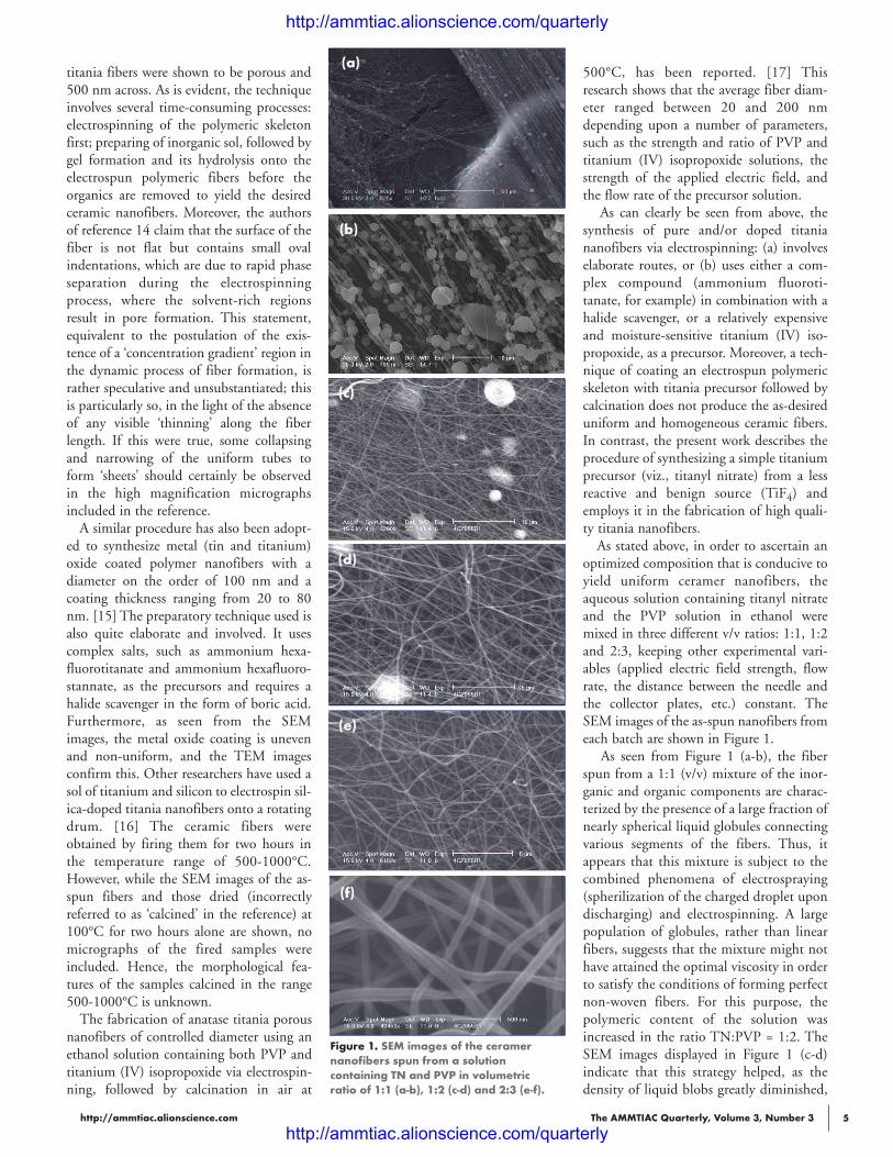
optimized composition that is conducive toyield uniform ceramer nanofibers, theaqueous solution containing titanyl nitrateand the PVP solution in ethanol weremixed in three different v/v ratios: 1:1, 1:2and 2:3, keeping other experimental vari-ables (applied electric field strength, flowrate, the distance between the needle andthe collector plates, etc.) constant. TheSEM images of the as-spun nanofibers fromeach batch are shown in Figure 1.
As seen from Figure 1 (a-b), the fiberspun from a 1:1 (v/v) mixture of the inor-ganic and organic components are charac-terized by the presence of a large fraction ofnearly spherical liquid globules connectingvarious segments of the fibers. Thus, itappears that this mixture is subject to thecombined phenomena of electrospraying(spherilization of the charged droplet upondischarging) and electrospinning. A largepopulation of globules, rather than linearfibers, suggests that the mixture might nothave attained the optimal viscosity in orderto satisfy the conditions of forming perfectnon-woven fibers. For this purpose, thepolymeric content of the solution wasincreased in the ratio TN:PVP = 1:2. TheSEM images displayed in Figure 1 (c-d)indicate that this strategy helped, as thedensity of liquid blobs greatly diminished,
Figure 1. SEM images of the ceramernanofibers spun from a solutioncontaining TN and PVP in volumetricratio of 1:1 (a-b), 1:2 (c-d) and 2:3 (e-f).
(a)
(b)
(c)
(d)
(e)
(f)
http://ammtiac.alionscience.com/quarterly
http://ammtiac.alionscience.com/quarterly

The AMMTIAC Quarterly, Volume 3, Number 36
though was not eliminated totally. Some evidence of fiber bend-ing can also be seen, which indicates that the ratio of the twocomponents in the spinning mixture still needs to be optimized.The 2:3 (v/v) mixture of TN:PVP appeared to form the mostdesired microstructure when electrospun, as could be seen fromthe nonwoven fibers of uniform thickness in Figure 1 (e-f ). Thesubsequent discussion pertains to the fibers which were electro-spun from a homogeneous solution containing the inorganic andorganic precursors in the volumetric ratio of 2:3.
The morphological features of the fired nanofibers of electro-spun titania are shown in Figure 2a. The intact nature of thefibers in the layered mats of titania that were present in the as-spun material can be discerned in the calcined sample as well.This is by virtue of the judicious firing scheme adopted in thiswork; even a slightly higher ramp rate has been found to causesevere fiber rupturing, rendering them into a powdery mass, dueto faster combustion of the polymer with a concomitant andsudden release of a copious amount of gaseous products. Theenergy dispersive spectrum (EDS) of the same is shown in Figure2b, where the signals due to oxygen and titanium alone are seen;no peak belonging to carbon is present, meaning that the heatingprofile selected in this work was able to eliminate polymericcomponents quantitatively.The TEM images of the nanofibers fired at 700°C as per the
schedule described in the previous section are shown in Figure 3.It is evident that the heat treatment used in the present work
has preserved the fibrous artifact in the processed material.Moreover, the titania fibers are porous and less than 100 nmacross; they are comprised of interconnected monosized grains,
making the structure quite breathable and therefore amenable forthe intended medical application. Using the wavelength of theelectron beam (0.0335Å) and the length of the SAED pattern onthe film, the interplanar distances (d-spacings) for successivediffractions were calculated. They match the d-spacings reportedin literature for the anatase phase of titania. This is corroboratedby the X-ray diffraction pattern of the powdered nanofibers, asshown in Figure 4; the selected area electron diffraction signatureof the calcined fibers is also shown as an inset.
CONCLUSIONTitanium dioxide nanofibers were successfully electrospun as apolymeric composite from a benign and inexpensive titaniumprecursor, viz., titanyl nitrate and polyvinyl pyrrolidone. The as-spun ceramer fibers possessing uniform thickness upon firingwere formed into breathable titanium dioxide nanomats ofanatase modification upon a single-stage firing in air at 700°C forone hour.
ACKNOWLEDGMENTZainab Al-Firdaus was part of this research during summer 2007,when she was an 8th grade student at Perrysburg Junior HighSchool. She is currently a sophomore at Perrysburg High School.
NOTES & REFERENCES* Corresponding author; e-mail address: [email protected]† Nanomats are 3-dimensional carpet-like, supportless, independent,modular structures with nearly identical porosity in their bulk. Thesespecialized nanostructured materials can be used either as such or incombination with other components, such as dyes or drugs or both, toenhance their anticipated functional attributes.[1] Kingrey, W.D., H.K. Bowen, and D.R. Uhlmann, Introduction toCeramics, 2nd ed., John Wiley, 1990.[2] Peblow, M., Nature, Vol. 429, 2004, p. 620.[3] Bozzi, A., T. Yuranova, and J. Kiwi, J. Photochem. Photobiol. A:Chem., Vol. 172, 2005, p. 27.[4] Bozzi, A., T. Yuranova, I. Guasaquillo, D. Laub, and J. Kiwi, J.Photochem. Photobio. A: Chem., Vol. 174, 2005, p. 156.[5] Meilert, K.T., D. Laub, and J. Kiwi, J. Molec. Catal. A, Vol. 237,2005, p. 101.[6] Yuranova, T., R. Mosteo, J. Bandata, D. Laub, and J. Kiwi, J. Molec.Catal. A, Vol. 244, 2006, p. 160.[7] Daoud, W.A., J.H. Xin, and Y. H. Zhang, Surf. Sci., Vol. 599, 2005,p. 69.[8] Li, W.J., C.T. Laurencin, E.J. Caterson, R.S. Tuan, and F.K. Ko, J.Biomed. Mater. Res. Vol. 60, 2002, p. 613.[9] Kenawy, E., J.M. Layman, J.R. Watkins, G.L. Bowlin, J.A.Matthews, D.G. Simpson and G.E. Wnek, Biomaterials, Vol. 24, 2003,p. 907.
Figure 2. (a) SEM showing the intact nature of the mat structure ofthe fired fibers and (b) EDS signature in the ceramer compositefired at 700°C/1h. Figure 3. TEM images of the ceramer nanofibers fired at 700°C/1h.
Figure 4. XRD signature of the nanofibers calcined at 700°C/1h(inset: SAED pattern).
(a) (b)
200 nm 100 nm
http://ammtiac.alionscience.com/quarterly
http://ammtiac.alionscience.com/quarterly

http://ammtiac.alionscience.com The AMMTIAC Quarterly, Volume 3, Number 3 7
[10] Azad, A.-M., unpublished research, 2007.[11] Eichenberg, D.J., “High-Voltage Droplet Dispenser,” NASATechBriefs, 2003, http://www.nasatech.com/Briefs/Nov03/LEW17190.html.[12] Azad, A.-M., Mater. Sci. Eng. A, Vol. 435–436, 2006, p. 468.[13] Azad, A.-M., M. Noibi, and M. Ramachandran, Bull. Polish Acad.Sci., Vol. 55, 2007, p. 195.
[14] Caruso, R.A., J.H. Schattka, and A. Greiner, Adv. Mater., Vol. 13,2001, p. 1577.[15] Drew, C., X. Liu, D. Ziegler, X. Wang, F.F. Bruno, J. Whitten,L.A. Samuelson, and J. Kumar, Nano Lett., Vol. 3, 2003, p. 143.[16] Choi, S., B.C. Chu, S.G. Lee, S.W. Lee, S.S. Im, S.H. Kim, andJ.Y. Park, J. Sol-Gel Sci. Tech., Vol. 30, 2004, p. 215.[17] Li, D. and Y. Xia, Nano Lett., Vol. 3, 2003, p. 555.
Dr. Abdul-Majeed Azad is an Associate Professor in the Department of Chemical Engineering at the University ofToledo; he has been serving the university in this capacity since August ’03. Dr. Azad began his career as a ResearchScientist studying fast breeder nuclear reactor materials with a special focus on their processing and characterizationaspects. His current interests are in the area of nanomaterials, including metals, functional ceramics and composites.Dr. Azad is particularly interested in the relevance of nanomaterials to clean energy, catalysis, sensors, biomedicalapplications and other nanotechnologies.
Ms. Sara Lynn McKelvey was born and raised in Toledo, Ohio. Ms. McKelvey received undergraduate degrees inchemical and bio-engineering from the University of Toledo in December 2008.
Ms. Zainab Al-Firdaus was born in Columbus, Ohio, and currently attends Perrysburg High School. Ms. Al-Firdausplans to attend The Ohio State University upon completion of high school. She is an ardent Jeopardu fan and plays thepiano.
AMMTIAC Success Story:Commercial Manufacturer Benefits from DoD Technology Transfer
Beyond the primary charge of providing technical solutions to thewarfighter, it is also a mission of the Information Analysis Centers(IACs) to transfer, or “spin-off,” innovative technologies to theUS industrial base, as AMMTIAC has recent-ly done. Through a commercial inquiry,AMMTIAC provided a manufacturer of wireand cable machinery with a machining solu-tion that employed technology originallydeveloped for the US Army to solve a produc-tion issue and improve product quality.The manufacturer identified the root cause of
the production issue as a poor surface finish onmachine components called forming rolls. Theserolls are grooved pieces of high strength steel used to shape individ-ual strands of wire so that they can be wrapped together to form alarger cable. Due to the weight of the components (60 lbs each) andthe complexity associated with machining the wire grooves, theproper surface finish needed to shape the wire strands is not readilyachieved by traditional machining methods (e.g., turning, grinding,etc). Engineers from AMMTIAC collaborated with the componentmanufacturer to evaluate possible solutions and decided the bestapproach is to apply a superfinish to the complex surface geometryof the forming rolls to achieve the desired surface finish.Chemically Accelerated Vibratory Surface Finishing (CAVSF),
more frequently referred to as Superfinishing, is a process that wasoriginally developed by the US Army to improve the surface
finish and fatigue life of compo-nents in helicopter transmissions.Superfinishing uses a chemically-
formulated conversion coating to oxidize thepeaks on a surface after which they are placed ina vibratory media container, where the oxidizedpeaks are removed, leaving a microscopically-smooth surface finish. Metallic componentsthat have undergone a superfinishing operationhave demonstrated a 300% improvement in thefatigue life of the surface. Transition of super-finishing technologies has netted significantresults in the automobile racing community, as
it has significantly improved the overall performance and servicelife of car transmissions and ring and pinion gears.Application of superfinishing technology to the forming rolls
produced a drastic improvement in the quality of the wire beingproduced. The improved surface finish (less than four micro-inches)has allowed the machinery manufacturer to produce individualstrands of wire that are free of defects, eliminating a long-standingproduction issue. The success achieved by superfinishing theforming rolls has lead the machinery manufacturer to considerpermanently using the superfinishing process in the productionof forming rolls. In addition, AMMTIAC is working with themachinery manufacturer to identify other machine componentsthat would benefit from the use of superfinishing technology.
http://ammtiac.alionscience.com/quarterly
http://ammtiac.alionscience.com/quarterly