Embed Size (px)
Citation preview

LA-UR-95-806
Quantum Cryptography
Richard J. Hughes
D. M. Alde, P. Dyer, G. G. Luther, G. L. Morgan and M. Schauer
University of CaliforniaPhysics Division
Los Alamos National LaboratoryLos Alamos, NM 87545
ABSTRACT
Quantum cryptography is a new method for secret communications offeringthe ultimate security assurance of the inviolability of a Law of Nature. In thispaper we shall describe the theory of quantum cryptography, its potentialrelevance and the development of a prototype system at Los Alamos, whichutilises the phenomenon of single-photon interference to perform quantumcryptography over an optical fiber communications link.
“ I am fairly familiar with all forms of secret writings, and am myselfthe author of a trifling monograph upon the subject, in which I analyseone hundred and sixty separate ciphers; but I confess that this one isentirely new to me. The object of those who invented the system hasapparently been to conceal that these characters convey a message ...”(Sherlock Holmes.1)
1. Introduction
Cryptology, the mathematical science of secret communications, has a long
and distinguished history of military and diplomatic uses dating back to the
ancient Greeks.2 In World War II, Allied successes in breaking the ciphers of
Germany and Japan played an important part in the outcome of the conflict and
the development of the modern computer.3 Today, the ability to ensure the
secrecy of military or diplomatic communications is as vital as ever, but
cryptography is also becoming more and more important in everyday life. With
the growth of computer networks for business transactions and communication of
confidential information there is an ever increasing need for encryption to ensure
that this information cannot be acquired by third parties. Remarkably, the
2
seemingly unrelated philosophical foundations of quantum mechanics are now
being brought to bear directly on the problem of communications security in the
potentially practical emerging technology of quantum cryptography.
In this paper we shall review the theory of quantum cryptography, its
potential applications and the development of an experimental prototype at Los
Alamos. We shall answer the questions: What is “ quantum” about quantum
cryptography? Will we need it? or, what if anything is “ wrong” with conventional
cryptography? What are the limitations imposed by “ practical” issues such as
losses and noise? What are the prospects for future improvements? What
hardware developments are desirable? and, What kind of secure communications
problem could it be used for?
The two main goals of cryptography are for a sender and an intended
recipient to be able to communicate in a form that is unintelligible to third parties,
and for the authentication of messages to prove that they were not altered in
transit. Both of these goals can be accomplished with provable security if sender
and recipient are in possession of shared, secret “ key” material. Thus, key
material, which is a truly random number sequence, is a very valuable commodity
even though it conveys no useful information itself. One of the principal problems
of cryptography is therefore the so-called “ key distribution problem.” How do the
sender and intended recipient come into possession of secret key material while
being sure that third parties (“ eavesdroppers” ) cannot acquire even partial
information about it? It is provably impossible to establish a secret key with
conventional communications, and so key distribution has relied on the
establishment of a physically secure channel (“ trusted couriers” ) or the
conditional security of “ difficult ” mathematical problems in public key
cryptography. However, provably secure key distribution becomes possible with
quantum communications. It is this procedure of key distribution that is
accomplished by quantum cryptography, and not the transmission of an encrypted
message itself. Hence, a more accurate name is quantum key distribution (QKD).
The most obvious security feature of QKD is that it is impossible to “ tap”
single quantum signals in the conventional sense. At a deeper level, QKD resists

3
interception and retransmission by an eavesdropper because in quantum
mechanics, in contrast to the classical world, the result of a measurement cannot
be thought of as revealing a “ possessed value” of a quantum state. Moreover,
Heisenberg’s uncertainty principle ensures that the eavesdropper’s activities must
produce an irreversible change in the quantum states (“ collapse of the
wavefunction” ) before they are retransmitted to the intended recipient. These
changes will introduce an anomalously high error rate in the transmissions
between the sender and intended recipient, allowing them to detect the attempted
eavesdropping. Thus, the two important security features of QKD are that
eavesdroppers cannot reliably acquire key material, and any attempt to do so will
be detectable.
The origins of quantum cryptography can be traced to the work of
Wiesner, who proposed that if single-quantum states could be stored for long
periods of time they could be used as counterfeit-proof money. Wiesner
eventually published his ideas in 1983,4 but they were of largely academic interest
owing to the impracticality of isolating a quantum state from the environment for
long time periods. However, Bennett and Brassard realised that instead of using
single quanta for information storage they could be used for information
transmission. In 1984 they published the first quantum cryptography protocol now
known as “ BB84” .5 A further advance in theoretical quantum cryptography took
place in 1991 when Ekert proposed6 that Einstein-Podolsky-Rosen (EPR)
entangled two-particle states could be used to implement a quantum cryptography
protocol whose security was based on Bell’s inequalities.7 Also in 1991, Bennett
and collaborators demonstrated that QKD was potentially practical by
constructing a working prototype system for the BB84 protocol, using polarised
photons.8
In 1992 Bennett published a “ minimal” QKD scheme (“ B92” ) and
proposed that it could be implemented using single-photon interference with
photons propagating for long distances over optical fibers.9 Since then, other
QKD protocols have been published10 and experimental groups in the UK,11
Switzerland12 and the USA13 have developed optical fiber-based prototype QKD

4
systems. The aim of these experiments has been to show the conceptual feasibility
of QKD, rather than to produce the definitive system, or to address a particular
cryptographic application. Thus, we can expect that the experiences with the
current generation of systems will lead to improvements towards demonstrating
the practical feasibility of QKD as well as a definition of the applications where it
could be used.
The remainder of this paper is organised as follows. In Sections 2 and 3 we
introduce some important ideas from cryptography to explain the significance of
QKD. In Section 4 we shall describe the B92 QKD protocol in detail, and then in
Section 5 we shall illustrate the immunity of QKD to eavesdropping. In Section 6
we describe some of the practical issues that arise in implementing QKD and in
Sections 7 and 8 we shall give some details about the QKD prototype that we have
developed at Los Alamos. Finally, in Section 9 we shall present some conclusions
and discuss the future possibilities for QKD development.
2. Cryptography
To explain the significance of quantum cryptography it is necessary to
describe some of the important features (and perils) of cryptography in general.
These points can be illustrated with one of the most famous literary examples of a
cipher: Sir Arthur Conan Doyle’s “ The Adventure of the Dancing Men.” 1 In this
story, Elsie, the American wife of an English gentleman, Hilton Cubbitt, is
terrorised by the appearance of chalked stick-figures outside her house. (See
Figure 1.) Sherlock Holmes is called in and quickly realises that the figures are not
the scribblings of children, but rather are a form of cryptography, in which each
letter of the alphabet has been substituted with a stick figure, known only to the
sender (Abe Slaney, “ the most dangerous crook in Chicago” ) and the intended
recipient, Elsie. This cryptosystem yields to the cryptanalytical powers of Sherlock
Holmes, who breaks the cipher after collecting only 62 characters, by observing
the relative frequencies of the different characters, identifying the most frequent
with the letter “ E” and using intuition.2 With this information the master
detective is able to compose his own cryptogram summoning Abe Slaney to Elsie’s

5
house. The criminal, believing that only Elsie could have composed a “ Dancing
Men” message, is promptly arrested by the police on his arrival.
This story illustrates several important cryptographic issues. It shows that
the two important and distinct aspects of cryptography (secrecy of
communications and authentication) can both be accomplished if sender and
recipient share a secret to start with (in this case the letter-equivalent of each
“ Dancing-Man” character). Secondly, this story shows (one of) the main
assumption(s) underlying cryptography: no matter how difficult it might appear to
be, we must assume that any cryptogram is susceptible to passive interception.
Finally, this story shows the complacency that is characteristic of the history of
cryptography: Abe believed that his cipher was “ unbreakable”
The “ Dancing Men” type of cipher, technically known as a monoalphabetic
substitution cipher, is clearly unsuitable for all except the most rudimentary
applications, which raises the question: are there shared secrets that are more
secure? By “ more secure” we mean that the encryption algorithm and shared
secret must be capable of ensuring the secrecy of communications for the useful
lifetime of the information being transmitted. In practice we can make a
distinction between “ tactical” and “ strategic” security. For example, if the
information is tactical military information this time might only be a few minutes
or hours, because over longer periods the tactical situation may have changed
sufficiently to render the information valueless. On the other hand, there are
communications such as diplomatic ones, which must “ never” fall to an
eavesdropper’s cryptanalytical attacks, no matter how much computing power is
brought to bear on the problem either now or in the future.14, 15 Indeed, there is
one cipher based on a shared secret which is provably unbreakable, and we shall
describe this for illustrative purposes in the next section.
3. Key material, key distribution and the “ one-time pad ”
In modern “ secret key,” or “ symmetric” cryptosystems, the general nature
of the encryption algorithm, E , by which a plaintext message, P, is rendered into a
cryptogram, C, can be publicly known, because in any particular communication it
6
depends on a parameter, known as a “ key” , K , which is a secret shared only by the
sender (known generically as “ Alice” )16 and intended recipient (known as “ Bob” ).
Indeed, a second important assumption of cryptography, known as Kirchoff’s
precept, is that the secrecy must reside entirely in the key and not the algorithm.2,
17 Thus, Alice generates the cryptogram
C E PK= b g , (1)
and sends it to Bob, who decrypts it
P E CK= −1b g , (2)
recovering the plaintext P. The transmission of the cryptogram takes place under
the nose of an eavesdropper (“ Eve” ) who clearly must not be able to acquire the
key, K , or she will be able to read Alice and Bob’s communications.
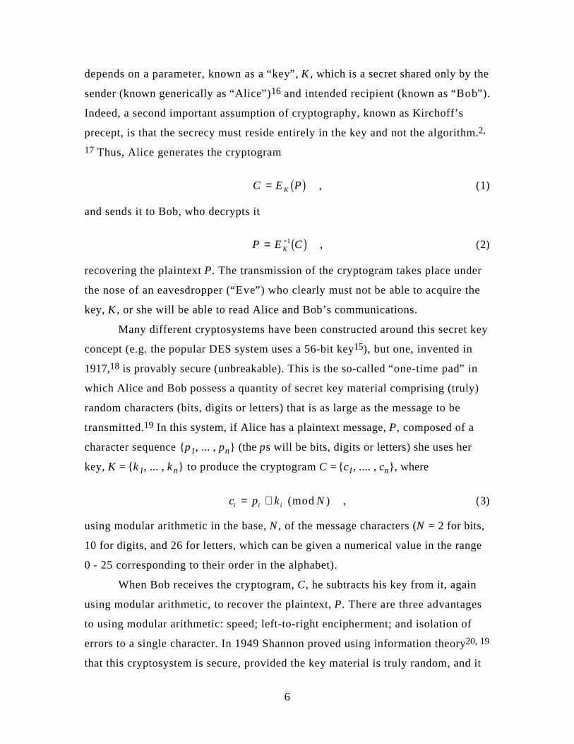
Many different cryptosystems have been constructed around this secret key
concept (e.g. the popular DES system uses a 56-bit key15), but one, invented in
1917,18 is provably secure (unbreakable). This is the so-called “ one-time pad” in
which Alice and Bob possess a quantity of secret key material comprising (truly)
random characters (bits, digits or letters) that is as large as the message to be
transmitted.19 In this system, if Alice has a plaintext message, P, composed of a
character sequence {p1, ... , pn} (the ps will be bits, digits or letters) she uses her
key, K = {k 1, ... , k n} to produce the cryptogram C = {c1, .... , cn}, where
c p k Ni i i= + (mod ) , (3)
using modular arithmetic in the base, N , of the message characters (N = 2 for bits,
10 for digits, and 26 for letters, which can be given a numerical value in the range
0 - 25 corresponding to their order in the alphabet).
When Bob receives the cryptogram, C, he subtracts his key from it, again
using modular arithmetic, to recover the plaintext, P. There are three advantages
to using modular arithmetic: speed; left-to-right encipherment; and isolation of
errors to a single character. In 1949 Shannon proved using information theory20, 19
that this cryptosystem is secure, provided the key material is truly random, and it
7
is used once and only once. The essence of the security is that, for an
eavesdropper, any given decryption is as likely as any other because of the
randomness of the key.
The one-time pad system was used for German and Soviet diplomatic
communications before and during WWII and by Communist spies during the
Cold War. It acquires its name from the practice of printing the key in the form of
paper pads, each sheet of which would be torn out and destroyed after being used
just once. A photocopy of a German diplomatic one-time pad from the World
War II era is shown in Figure 2.
However, if the one-time pad is truly unbreakable, why is it not used
exclusively? The answer to this question involves the key generation, distribution
and management problems (which also apply to any other secret key
cryptosystem). First of all, Alice must generate some truly random numbers,
which is not as easy as it might seem. For instance, a simple pseudo-random
number generator on a computer would not give a secure key because it will
always produce the same sequence for a given “ seed” value. To avoid being in this
“ state of sin” 21 a physical “ noise” source could be used to generate the key
material. A fictional example of such a scheme, using atmospheric radio noise is
described in Tom Clancy’s novel “ The Sum of all Fears.” 22
Once Alice has generated enough key material to encrypt any anticipated
communications she must arrange for Bob to receive a copy of the key without
Eve being able to obtain even partial knowledge of it. If Alice and Bob are able to
meet beforehand they can accomplish this key distribution in secrecy. But if they
are unable to meet, and they share no secret key material beforehand, Alice
cannot simply transmit the key material to Bob because by the main assumption
of cryptography this transmission is susceptible to passive eavesdropping, which
would allow Eve to also acquire the key. Indeed, the only secure method of
transmitting the one-time pad would require another one-time pad to encrypt it!
(It can be proved that if Alice and Bob possess no secret key material initially they
cannot establish a certifiably secure shared key.23, 8) The conventional approach
to this key distribution problem is for Alice and Bob to establish a secure channel,

8
relying on “ physical security” which in reality can make it “ difficult ” but not
impossible for third parties (Eve) to acquire key information, and they must store
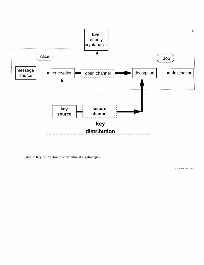
the key material securely until it is to be used. (See Figure 3.)
The necessity for generating, distributing and storing the key material in
advance renders the one-time pad system (and other secret key cryptosystems)
vulnerable to the “ insider threat.” Trusted individuals with access to Alice’s or
Bob’s stored key material could copy it and provide it to Eve. Furthermore, the
cumbersome logistics of generating the huge quantities of key and transporting it
securely make the one-time pad system susceptible to misuse, undermining its
security. It is reported24 that the demands placed on Soviet diplomatic
communications at the start of WWII were so great that one-time pads were re-
used,25 allowing cryptanalysts to unmask the Rosenberg spy ring and the atom-spy
Klaus Fuchs.26
In theory the one-time pad is unbreakable, but in practice, as we have seen,
it has been very difficult to use. This is one reason for the popularity of public key
cryptography systems which are “ difficult,” but not impossible, to break, and easy
to use.17 We do not have space here to describe these very interesting systems,
except to point out that they provide “ conditional” security: Eve’s computing
power now and in the foreseeable future is assumed to be limited. However,
advances in computer algorithms and hardware threaten to undermine the security
of these systems. They are potentially vulnerable in the sense that what is
“ difficult ” today may be much less so in the future. A recent example illustrates
this point rather well. In 1977 a challenge was made in Scientific American27 to
break a message encrypted using the RSA method.16, 15, 28 To do so required
factoring a 129-digit number into its 64- and 65-digit prime factors, and this was
projected to take ~4x10¹⁶ years (about one million times the age of the universe).
However, in 1994 factoring algorithms29 and networking of computer resources
had advanced to the level where the factorisation only took 8 months (4,000
MIPS-years).30 There is no reason to believe that that this factoring speed could
not be further increased. For instance, a recently invented algorithm for the yet-
to-be-constructed quantum computer31 would permit factoring of RSA-129 in a

9
few seconds if it ran at the speed of a desktop PC.32 Thus, unforeseen
improvements in algorithms or computing power would allow Eve to “ reach back
in time” and break encrypted communications before they had ceased to be of
value.
In the light of these observations it would clearly be an important
cryptographic breakthrough to have a new communication method over an
“ open” channel that would allow Alice and Bob to establish a provably secure key
which, moreover, would allow them to detect if Eve was monitoring their
transmissions. Such a communications system would allow Alice and Bob to
establish a secret key at the time it is required for encrypted communication. This
key could even be a one-time pad, and so such a scheme would facilitate real-time
unbreakable encryption of communications, and avoid the security problems that
we have discussed above. Quantum key distribution is precisely such a
breakthrough.
4. Quantum key distribution
To understand QKD we must first move away from the traditional key
distribution metaphor of Alice sending particular key data to Bob. Instead, we
should have in mind a more symmetrical starting point, in which Alice and Bob
initially generate their own, independent random number sets, containing more
numbers than they need for the key material that they will ultimately share. Next,
they compare these sets of numbers to distil a shared subset, which will become
the key material. It is important to appreciate that they do not need to identify all
of their shared numbers, or even particular ones, because the only requirements
on the key material are that the numbers should be secret and random. They can
attempt to accomplish a secret distillation if Alice prepares a sequence of tokens,
one kind for a “ 0” and a different kind for a “ 1” , and sends a token to Bob for
each bit in her set. Bob proceeds through his set bit-by-bit in synchronisation with
Alice, and compares Alice’s token with his bit, and replies to Alice telling her
whether the token is the same as his number (but not the value of his bit). With
Bob’s information Alice and Bob can identify the bits they have in common. They
10
keep these bits, forming the key, and discard the others. If one of Alice’s tokens
fails to reach Bob this does not spoil the procedure, because it is only tokens that
arrive which are used in the distillation process.
The obvious problem with this procedure is that if the tokens are classical
objects they carry the bit values before they are observed by Bob, and so they
could be passively monitored by Eve. However, we shall now see that it is possible
to generate a secure key if the tokens are quantum objects. We shall describe the
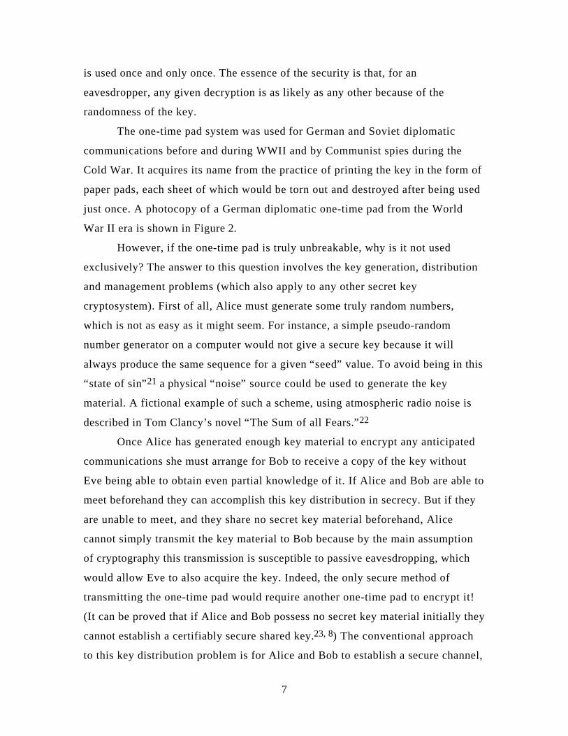
B92 QKD protocol in terms of the preparation and measurement of states in a
two-dimensional Hilbert space such as that of a spin-1/2 particle. The spin
operators σ1, σ2, σ3, obey the algebra
σ σ ε σi j ijk ki i j k, , , , , ,= =2 1 2 3 , (4)
and we may introduce a basis of states with spin-up (A ) or spin-down (B ) along
the z -axis
σ3
A
B=
+ A
− B
RS|
T|
RS|
T|
, (5)
satisfying the orthonormality relations
A A = B B =
A B =
1
0
. (6)
From these states we can also make eigenstates with spin-up or spin-down along
the x-axis
σ1
→
←=
+ →
− ←
RS|
T|
RS|
T| , (7)
where → = A + B−2 1 2e j and ← = A − B−2 1 2e j .

11
A (von Neumann) measurement in quantum theory is a projection
operator in Hilbert space.33 For example, a measurement for spin-down along the
z -axis is represented by the projection operator
PB = B B , (8)
and similarly a measurement for spin-down along the x-axis is represented by
P← = ← ← , (9)
The result of a measurement P on a state ψ is given by the “ collapse of the
wavefunction”
ψ
ψψ
ψ ψ
ψψ
ψ ψ
→−−
−
R
S|||
T|||
P
PP
P
PP
with probability
with probability1
11
b gb g b g
, (10)
where we shall describe the first outcome as a “ pass” and the second as “ fail.”
Here we have defined the norm as
φ φ φ≡1 2
. (11)
Thus, the outcome of a measurement in quantum mechanics is, in general, only
predictable with some probability.
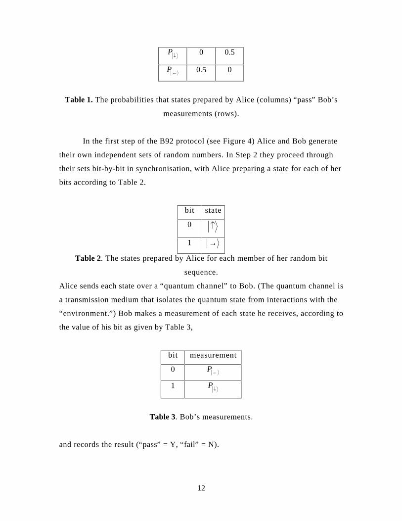
For the B92 protocol Alice has two non-orthogonal state preparations: A
or → ; and Bob can make two non-orthogonal measurements: PB or P← . The
“ pass” probabilities of the various preparation-measurement combinations are
given in Table 1.
A →
12
PB 0 0.5
P← 0.5 0
Table 1. The probabilities that states prepared by Alice (columns) “ pass” Bob’s
measurements (rows).
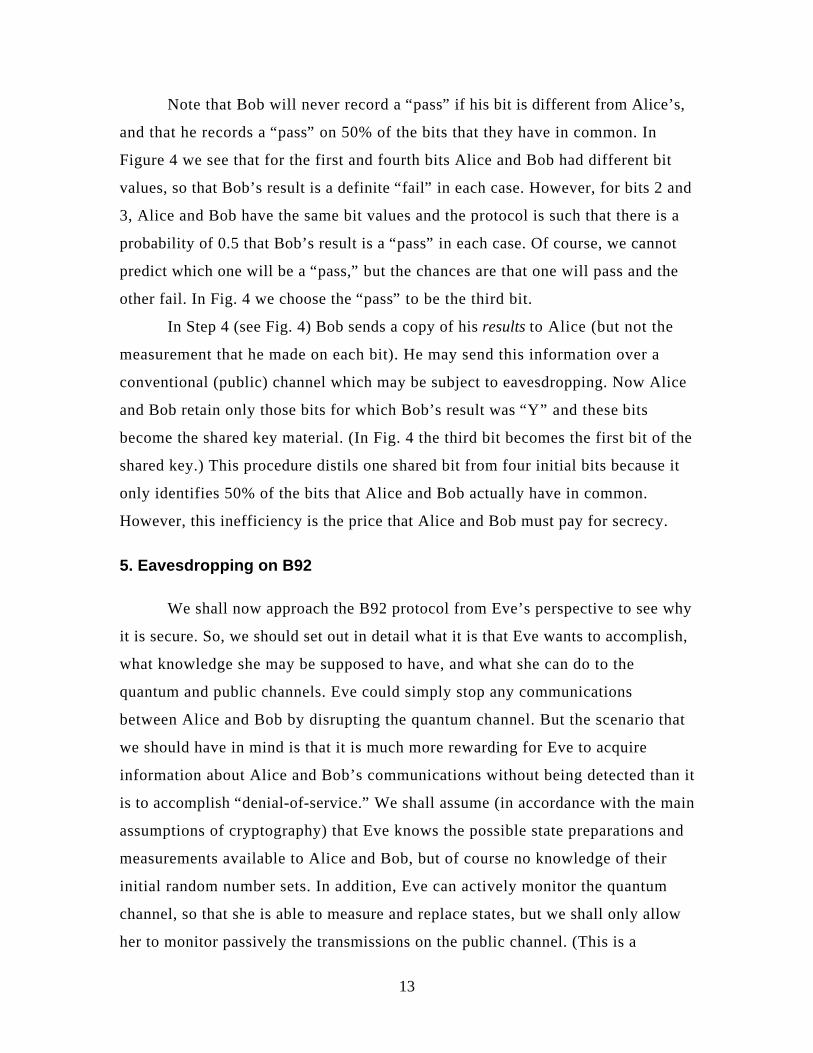
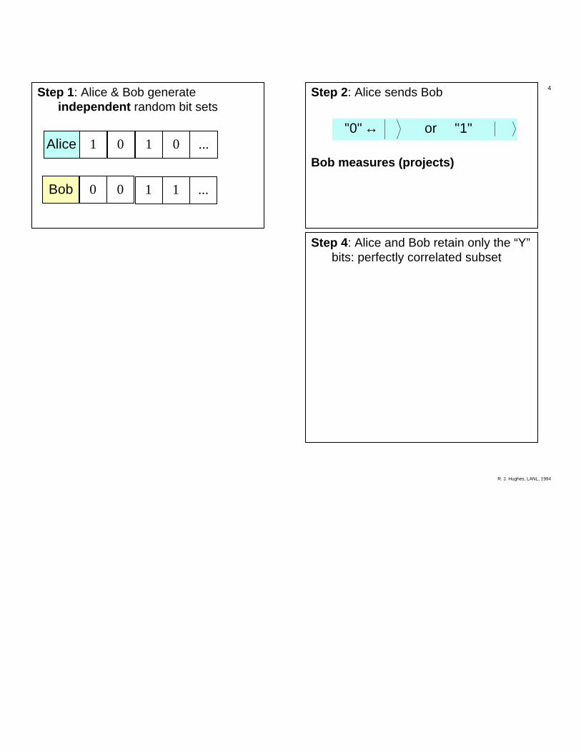
In the first step of the B92 protocol (see Figure 4) Alice and Bob generate
their own independent sets of random numbers. In Step 2 they proceed through
their sets bit-by-bit in synchronisation, with Alice preparing a state for each of her
bits according to Table 2.
bit state
0 A
1 →
Table 2. The states prepared by Alice for each member of her random bit
sequence.
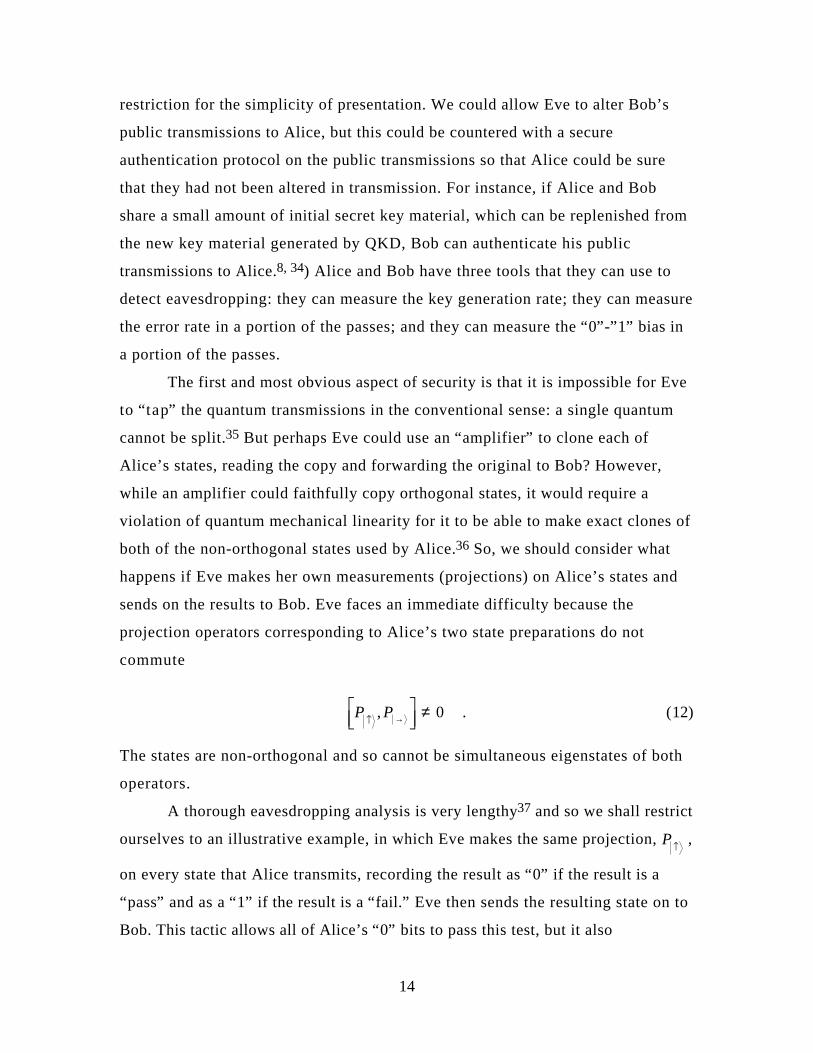
Alice sends each state over a “ quantum channel” to Bob. (The quantum channel is
a transmission medium that isolates the quantum state from interactions with the
“ environment.” ) Bob makes a measurement of each state he receives, according to
the value of his bit as given by Table 3,
bit measurement
0 P←
1 PB
Table 3. Bob’s measurements.
and records the result (“ pass” = Y, “ fail” = N).
13
Note that Bob will never record a “ pass” if his bit is different from Alice’s,
and that he records a “ pass” on 50% of the bits that they have in common. In
Figure 4 we see that for the first and fourth bits Alice and Bob had different bit
values, so that Bob’s result is a definite “ fail” in each case. However, for bits 2 and
3, Alice and Bob have the same bit values and the protocol is such that there is a
probability of 0.5 that Bob’s result is a “ pass” in each case. Of course, we cannot
predict which one will be a “ pass,” but the chances are that one will pass and the
other fail. In Fig. 4 we choose the “ pass” to be the third bit.
In Step 4 (see Fig. 4) Bob sends a copy of his results to Alice (but not the
measurement that he made on each bit). He may send this information over a
conventional (public) channel which may be subject to eavesdropping. Now Alice
and Bob retain only those bits for which Bob’s result was “ Y” and these bits
become the shared key material. (In Fig. 4 the third bit becomes the first bit of the
shared key.) This procedure distils one shared bit from four initial bits because it
only identifies 50% of the bits that Alice and Bob actually have in common.
However, this inefficiency is the price that Alice and Bob must pay for secrecy.
5. Eavesdropping on B92
We shall now approach the B92 protocol from Eve’s perspective to see why
it is secure. So, we should set out in detail what it is that Eve wants to accomplish,
what knowledge she may be supposed to have, and what she can do to the
quantum and public channels. Eve could simply stop any communications
between Alice and Bob by disrupting the quantum channel. But the scenario that
we should have in mind is that it is much more rewarding for Eve to acquire
information about Alice and Bob’s communications without being detected than it
is to accomplish “ denial-of-service.” We shall assume (in accordance with the main
assumptions of cryptography) that Eve knows the possible state preparations and
measurements available to Alice and Bob, but of course no knowledge of their
initial random number sets. In addition, Eve can actively monitor the quantum
channel, so that she is able to measure and replace states, but we shall only allow
her to monitor passively the transmissions on the public channel. (This is a
14
restriction for the simplicity of presentation. We could allow Eve to alter Bob’s
public transmissions to Alice, but this could be countered with a secure
authentication protocol on the public transmissions so that Alice could be sure
that they had not been altered in transmission. For instance, if Alice and Bob
share a small amount of initial secret key material, which can be replenished from
the new key material generated by QKD, Bob can authenticate his public
transmissions to Alice.8, 34) Alice and Bob have three tools that they can use to
detect eavesdropping: they can measure the key generation rate; they can measure
the error rate in a portion of the passes; and they can measure the “ 0” -” 1” bias in
a portion of the passes.
The first and most obvious aspect of security is that it is impossible for Eve
to “ tap” the quantum transmissions in the conventional sense: a single quantum
cannot be split.35 But perhaps Eve could use an “ amplifier” to clone each of
Alice’s states, reading the copy and forwarding the original to Bob? However,
while an amplifier could faithfully copy orthogonal states, it would require a
violation of quantum mechanical linearity for it to be able to make exact clones of
both of the non-orthogonal states used by Alice.36 So, we should consider what
happens if Eve makes her own measurements (projections) on Alice’s states and
sends on the results to Bob. Eve faces an immediate difficulty because the
projection operators corresponding to Alice’s two state preparations do not
commute
P PA →LNM
OQP ≠, 0 . (12)
The states are non-orthogonal and so cannot be simultaneous eigenstates of both
operators.
A thorough eavesdropping analysis is very lengthy37 and so we shall restrict
ourselves to an illustrative example, in which Eve makes the same projection, PA ,
on every state that Alice transmits, recording the result as “ 0” if the result is a
“ pass” and as a “ 1” if the result is a “ fail.” Eve then sends the resulting state on to
Bob. This tactic allows all of Alice’s “ 0” bits to pass this test, but it also

15
erroneously passes 50% of Alice’s “ 1” bits, giving Eve only a 0.75 probability of
correctly identifying a “ 0” . On the other hand, Eve can with certainty identify the
25% of Alice’s initial sequence which are the “ 1” states that fail her test. But, the
nature of quantum measurements is such that Eve irreversibly alters all of Alice’s
“ 1” states so that 50% of them are A -states and the other 50% are B -states
when they reach Bob. Now, if Bob tests either of these states with his “ 0” -
measurement there will be a 50% probability that the state will pass, in conflict
with 0% probability of this happening in the absence of eavesdropping. (There is
also a bias introduced into Bob’s results: more than 50% of his results are “ 0” s. Of
course, a clever Eve would use a different strategy which did not introduce this
asymmetry.)
The net result of Eve’s activities is that she has only reliably identified
Alice’s “ 1” s, at the expense of introducing a 25% error between Alice’s and Bob’s
key material. Thus, Alice and Bob can sacrifice a portion of their key to test the
error rate. If the rate is found to be high they will know that Eve has been
listening, and they would not use the key material.
If quantum mechanics was merely a statistical theory as envisioned by
Einstein,38 in which probabilities arose from our inability to produce
experimentally dispersion-free ensembles with sharp values for all observables
simultaneously, then QKD would not be secure. It is the remarkable feature of
quantum mechanics that measurements do not reveal pre-existing values,39 which
is in such strong contrast to classical physics, that ultimately underlies the security
of QKD.
6. Practical implementations of QKD
Perhaps the most obvious way to implement the QKD quantum channel is
with single-photon polarization states, such as the preparation of vertical and
right-handed-circular polarizations, and the measurement of horizontal linear and
left-handed-circular polarizations. However, another set of single-photon states,
which we shall call “ phase” states, have the algebraic properties required for

16
quantum cryptography and can be constructed by allowing a photon to impinge on
a simple beamsplitter.
We can express the action of a lossless beamsplitter in terms of photon
creation and annihilation operators (with frequency and polarization labels
suppressed) as a (unitary) transformation from the two “ in” modes to the two
“ out” modes (see Fig. 5a),40 as
a a ia
a e a ia
out in in
outi
in inA
1 1 2 1 2
2 12 2 1
2
2
b g b g b g
b g b g b g
= +
= +
−
− φ
, (13)
where we have incorporated an adjustable phase shift, φΑ, in the second output.
Here
a a a a a a
a a a a
a a
in in in in in in
in in in in
in in
1 2 1 2 1 2
1 1 2 2
1 2
0
1
0 0 0
b g b g b g b g b g b g
b g b g b g b g
b g b g
, , ,
, ,
= LNM
OQP = L
NMOQP =
LNM
OQP = L
NMOQP =
= =
† †
† † , (14)
where 0 is the “ vacuum” (no photon) state, and similarly for the “ out”
operators.(The factors of “ i” arise from the phase change on reflection.)
Thus, if we equip Alice with this beamsplitter and she introduces a single
photon state at the “ in” -port “ 1”
in ain1 1 0b g b g= † , (15)
this amounts to a preparation of the non-orthogonal “ out” states
A ≡ +LNM
OQP =
→ ≡ −LNM
OQP =
−
−
2 0 0
2 0 2
1 2 1 2
12 1 2
a ia
a a
out out A
out out A
b g b g
b g b g
† †
† †
for
or
for
φ
φ π . (16)
17
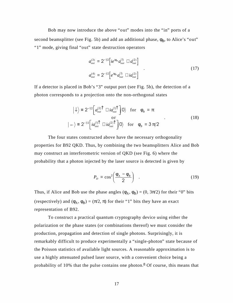
Bob may now introduce the above “ out” modes into the “ in” ports of a
second beamsplitter (see Fig. 5b) and add an additional phase, φΒ, to Alice’s “ out”
“ 1” mode, giving final “ out” state destruction operators
a ie a a
a e a ia
outi
out out
outi
out out
B
B
( ) ( )
( ) ( )
3 12 1 2
4 12 1 2
2
2
= +
= +
−
−
φ
φ
b g
b g . (17)
If a detector is placed in Bob’s “ 3” output port (see Fig. 5b), the detection of a
photon corresponds to a projection onto the non-orthogonal states
B ≡ +LNM
OQP =
← ≡ +LNM
OQP =
−
−
2 0
2 0 3 2
1 2 2 1
12 1 2
a ia
ia ia
out out B
out out B
b g b g
b g b g
† †
† †
for
or
for
φ π
φ π . (18)
The four states constructed above have the necessary orthogonality
properties for B92 QKD. Thus, by combining the two beamsplitters Alice and Bob
may construct an interferometric version of QKD (see Fig. 6) where the
probability that a photon injected by the laser source is detected is given by
PDA B= −F
HGIKJcos2
2
φ φ . (19)
Thus, if Alice and Bob use the phase angles (φA , φB) = (0, 3π/2) for their “ 0” bits
(respectively) and (φA , φB) = (π/2, π) for their “ 1” bits they have an exact
representation of B92.
To construct a practical quantum cryptography device using either the
polarization or the phase states (or combinations thereof) we must consider the
production, propagation and detection of single photons. Surprisingly, it is
remarkably difficult to produce experimentally a “ single-photon” state because of
the Poisson statistics of available light sources. A reasonable approximation is to
use a highly attenuated pulsed laser source, with a convenient choice being a
probability of 10% that the pulse contains one photon.8 Of course, this means that
18
~ 90% of the pulses contain no photon, but this is the price that must be paid (in
data rate) for having < 1% of pulses containing two or more photons, which are
the ones susceptible to a beamsplitting attack. A more sophisticated light source
could be based on the phenomenon of parametric down conversion41 in which a
photon entering a non-linear crystal has a small probability of producing a pair of
lower-frequency photons. By triggering on one of the down-converted photons
true “ single photons” have been produced as the other member of the pair.42
At first sight, it appears that free-space QKD would be immensely difficult
over any but the shortest distances because of the presence of background
photons and the difficulties of directing the photons onto a remote detector.
Nevertheless, the first working QKD system was based on polarized photons
propagating in a tube over a distance of 30 cm.8 However, these authors proposed
that for longer distance communications optical fibers would be more suitable
because the photons would be guided from source to detector. Moreover, because
optical fibers are widely used in telecommunications there are commercially
available components, possibly allowing a system to be constructed that can
perform quantum cryptography over an installed communications system.
Optical fibers, although possessing the good feature of guiding photons
from source to detector, bring their own problems that largely determine the
operating characteristics of a system. Probably the first question to be answered is:
what wavelength should we choose to operate at ? Two factors are relevant to this
question. At what wavelengths is single-photon detection possible with non-
negligible efficiency? and at what wavelengths do optical fibers have low
attenuation?
For photons in the wavelength range of 600 - 800 nm there are
commercially available single-photon counting modules based on silicon
avalanche photodiodes (APDs), which have high efficiencies (< 90%) and low
noise rates ( ~ 50 Hz when cooled to ~ -25 °C). However, the attenuation of
(single-mode) optical fibers is quite high in this wavelength range (~ 3 dB/km),43
which will adversely affect the data rate and the noise rate if we choose to operate
19
in this region. (The loss mechanism is predominantly Rayleigh scattering out of
the fiber.)
Conversely, optical fibers have much lower attenuation at 1.3 µm
(~ 0.3 dB/km), and lower again at 1.55 µm, but although there are commercially
available germanium (Ge) and indium-gallium arsenide (InGaAs) APDs that are
sensitive to light at these infrared wavelengths, there are no commercially
available single-photon counting modules. Nevertheless, several groups have
shown that these devices can detect single photons at 1.3 µm if they are first
cooled to reduce noise, and operated in so-called Geiger mode, in which they are
biased above breakdown.44 An incoming photon liberates an electron-hole pair,
which with some probability initiates an avalanche current, whose detection
signals the arrival of the photon. For our project we decided that the propagation
distance advantages of the 1.3-µm wavelength were such that we characterized the
performance of several APDs (both Ge and InGaAs) for single-photon detection
at this wavelength.
Several parameters are important in characterizing the detector
performance: single-photon detection efficiency; intrinsic noise rate (dark counts);
and time resolution. We measured absolute detection efficiencies of 10 - 40%, (for
InGaAs APDs), but noise rates that are ~ 1,000 times higher than for Si-APD
photon counting modules at 800 nm. However, our detectors also have very good
time resolutions (~ few 100 ps), which can be utilised to compensate for the higher
intrinsic noise rate because of the low dispersion of optical fibers at 1.3 µm. Thus,
if a 1.3-µm photon is injected into a fiber in a short wavepacket (300-ps, say) it will
emerge for the far end without being significantly stretched out in time and so,
because we know that the photon will be expected within a short time window we
need only consider the probability of a noise count in this short time interval
(~ 5x10⁻⁶ for 50-kHz noise rate).
Once we had established that single 1.3-µm photons can be detected with
acceptably low-noise background, we had to decide which photon states are most
suited for quantum key distribution: polarization and/or phase? For a polarization
20
scheme we would have to propagate two non-orthogonal polarization states down
the fiber. An immediate difficulty is that we need to know the relationship
between vertical polarization (say) at the fiber input and the output polarization,
because the birefringence introduced by bends in the fiber will, in general, convert
a linear polarization input state into an elliptically polarized output. Furthermore,
this birefringence means that a given length of fiber will, at any instant, have
stable “ fast” and “ slow” propagation modes which will be orthogonally polarized.
The difference in propagation speeds45 (polarization mode dispersion or PMD)
typically amounts to about a π-phase difference over (a beat length of) 10 cm to
1 m of fiber.46 So, if we align one of the QKD polarization states with the fast axis
(say) then the other non-orthogonal state will be gradually depolarized during
propagation once its two component polarizations become separated by more
than the coherence length of the light source. Thus, PMD will make a polarization
QKD scheme difficult for long propagation distances (> few km). Nevertheless
two groups have demonstrated polarization-based QKD over ~ 1 km of fiber.
However, we decided to avoid these difficulties of polarization-encoding in-fiber
and to use instead a phase-encoding scheme similar to the BT group’s in UK,11
who have already demonstrated QKD over 10 km of fiber in a laboratory. As we
shall see we still need to control the photons’ polarization in this method, but we
avoid the problems of non-orthogonal polarization states.
7. Single-photon interference for optical fiber QKD
If we were to simply use optical fibers for each of the interfering paths in
Figure 6 we would have a very unstable interferometer for all but the shortest
propagation distances. However, a more stable system can be produced by
multiplexing both paths onto a single fiber in a design first proposed by Bennett.9
In this design (see Fig. 7) Alice and Bob have identical, unequal-arm Mach-
Zehnder interferometers with a “ short” path and a “ long” path, with one output
port of Alice’s interferometer optically coupled to one of the input ports of Bob’s.
The difference of the light travel times between the long and short paths, ∆T , is

21
much larger than the coherence time of the light source, so there can be no
interference within each small interferometer. However, interference can occur
within the coupled system.
A photon injected into one of the input ports of Alice’s interferometer
from the attenuated pulsed laser source (“ L ” in Figure 7) therefore has a 50%
probability of entering Bob’s interferometer, in a wave packet that is a coherent
superposition of two pieces that are separated in time by ∆T , corresponding to an
amplitude for it to have taken the “ short” path, and a delayed component which
took the “ long” path. On entering Bob’s interferometer each component of the
wave packet is again split into a “ short” component and a “ long” component, so
that at each output port there are three “ time windows” in which the photon may
arrive. The first of these (“ prompt” ) corresponds to the “ short-short” propagation
amplitude; which is followed after a delay of ∆T by the “ central” component
comprising the “ short-long” and “ long-short” amplitudes; and finally, after a
further time ∆T , the “ delayed” time window corresponds to the “ long-long”
amplitude.
There is no interference in the “ short-short” or “ long-long” amplitudes, so
the probability that the photon arrives in either of these time windows in either of
Bob’s output ports is 1/16 (we assume 50/50 beamsplitters and lossless mirrors).
However, because the path-length differences in the two small interferometers are
identical (to within the coherence length of the light source) interference does
occur in the “ central” time window between the “ short-long” and “ long-short”
amplitudes. Indeed, because Alice and Bob can control the path length of their
“ long” paths with adjustable phases φA or φB, respectively, the probability that the
photon emerges in the “ central” time window at the detector (“ D ” in Figure 7) in
the output port shown is
P A B= + −1
81 cosφ φb g . (20)
Note that within a factor of four this expression is identical with the photon
arrival probability for the simple interferometric version of B92, and that, of the

22
two interfering paths one (“ long-short” ) is controlled by Alice and the other
(“ short-long” ) is controlled by Bob just as in the simple interferometer of Fig. 6.
Thus, by sacrificing a factor of four in data rate this time-multiplexed
interferometer can be used to implement QKD based on single-photon
interference. (The photons “ lost” in the prompt and delayed time windows are
useful to test for a highly invasive Eve.9)
In order to be sure that we understood single-photon interference in such a
configuration we first constructed a time-multiplexed interferometer, from
beamsplitters and mirrors, with ~ 500-ps path differences, and directed highly
attenuated 30-ps pulses of 1.3-µm light with a 10-kHz repetition rate into one of
the input ports. At one of the output ports light was collected by a microscope
objective and directed onto one of our cooled InGaAs APDs, from which a
photon time-of-arrival spectrum was accumulated with the mirrors in a fixed
position. Then the mirrors were moved to a new position and a new time spectrum
recorded. As expected, interference was observed in the central time window with
a number of counts corresponding to an average number of photons per pulse of
0.07. Thus interference was seen with only one photon in the device at a time.
We next constructed an optical fiber version of the time-multiplexed
interferometer in which each of Alice’s and Bob’s interferometers are built from
two 50/50 fiber couplers instead of beamsplitters. (See Figure 8.). Each coupler has
two input legs and two output legs: a photon entering on one leg has a 50%
probability to emerge from either of the output legs. No mirrors are required
because the output fiber legs from the first coupler convey the photons to the
input legs of the second coupler via a long fiber path or a short path (∆T~8.5 ns).
One of the output legs of Alice’s interferometer is connected by a long optical
fiber path to one of the input legs of Bob’s interferometer. Finally, photons
emerge from one of the output legs of Bob’s interferometer into a fiber pigtailed,
cooled InGaAs APD detector.
For our first system we constructed the entire optical path from so-called
polarization-maintaining (PM) fiber in order to ensure that the two interfering
amplitudes had identical polarizations, and also because the electro-optic phase

23
shifters in each of the “ long” paths, which we use to adjust the optical path
lengths, only leave specific linear polarizations unchanged. (We also included an
air-gap in Alice’s “ short” path so as to adjust the lengths of the two interfering
paths to be equal.) The phase modulators are fiber-pigtailed devices in which
photons propagate through a waveguide in a non-linear crystal whose refractive
index changes when an electric field is applied. The amount of phase change, φ,
for a given voltage, V , can be expressed as
φπ
=FHG
IKJ
−cos 1 V
V , (21)
where the voltage, Vπ, required for a π-phase change is about three times greater
for the TE mode than the TM mode. (In our interferometer the photon
polarization was therefore aligned for TM-mode propagation. Phase modulation
rates of up to several GHz are possible with these devices.) For longer
propagation distances, where we will have to use ordinary single-mode fiber, we
will use a polarization controller47 in Bob’s interferometer to rotate the
polarization back to the linear state required for his phase modulator.
A linearly polarized “ single-photon” is generated by applying a 300-ps
electrical pulse to a low-power, fiber-pigtailed semiconductor laser whose output
in then attenuated before coupling into the interferometer. The electrical pulse is
also the “ start” signal for a time-interval analyzer and applies the pulsed-bias gate
signal to the detector after a delay corresponding to the light transit time through
the system. The detector avalanche acts as the “ stop” signal. Figure 9 shows a time
spectrum of photon arrival times. The 8.5-ns separation of the different paths is
clearly visible, as is the 300-ps width of the laser pulse. The unequal height of the
“ short-short” and “ long-long” peaks is due to attenuation in the phase
modulators.
To turn this optical system into a QKD device we have placed it under the
control of two personal computers: one to control the overall timing and to set
Alice’s phases, and the other to set Bob’s phases and record his results (see Figure
10). The computers are linked together over Ethernet, forming the public channel,

24
in order to initialize their activities and to perform the results-transfer step of the
QKD. A key sending procedure starts with Alice’s and Bob’s computers first
generating independent sets of 1,024 random bits. (We used pseudorandom
number generation for this experiment.) Each of these sets of bits is loaded into
the memory of a digital-to-analogue converter (DAC). When this is accomplished,
key sending starts under the control of Alice’s master timer. In our first
experiment this clock ran at a rate of 100 kHz, but used ten “ ticks” of the clock to
set one bit. During this time: the contents of the one memory location in each
DAC were used to set voltages on the phase modulators corresponding to the B92
protocol; the laser was pulsed once and the detector gated open; and the output of
the detector in the central time window recorded to Bob’s computer. The
procedure was then repeated with the next bit, and so on, until all 1,024 bits were
used up. At the end of this procedure, Bob’s computer had a file recording the bit
number (1 - 1,024), the bit value (“ 0” or “ 1” ) and whether the detector fired or not
(“ hit” or “ miss” ). Then, Alice’s computer received over the Ethernet link a file
from Bob of the “ hit” or “ miss” status for each bit number. With this information
Alice and Bob retain only the bits corresponding to “ hits,” which become the key
material. More sets of 1,024 bits are generated and sent until a long enough key is
built up to encrypt the message that is to be sent.
We have carried out key generation with this system over a short distance
and are now rebuilding the system to improve its stability and to go to longer
distances. We are able to have fiber propagation distances of up to 1 km within
our laboratory, and in the future we hope to explore the practical feasibility of our
QKD system over a distance of 15 km of installed fiber that links two of the
Technical Areas at Los Alamos.
In our system it will be possible to type in a short message on Alice’s
computer, which will then convert it into ASCII code and generate as many key
bits as there are bits in the code. The message will be encrypted by adding the key
to the ASCII codes, the characters corresponding to the new ASCII codes will be
displayed on Alice’s computer, and sent over the Ethernet to Bob’s computer
25
where they are displayed again. Bob’s computer will then subtract its key to
recover the original message.
8. Data rate and error rate
Several factors make the key generation rate of any QKD system
considerably slower than the laser pulse rate. Firstly, the “ single-photon”
requirement introduces a factor of ten reduction in rate because 90% of the laser
pulses contain no photon. Then there are attenuation losses during propagation,
which would amount to about a factor of four over 10 km of optical fiber. The
QKD procedure itself has an intrinsic inefficiency of only identifying one shared
bit from four initial bits, which is reduced by a further factor of four in our
scheme, resulting in an additional factor of sixteen reduction in key rate. Finally,
there is the detector efficiency to be included, which in our case was only about
20%. Overall, the key generation rate with these parameters is about 1/3,000 of
the laser pulse rate, and would be reduced further over greater propagation
distances because of the additional fiber attenuation. However, the useful distance
is limited not so much by the key rate as by the bit error rate (BER) which must
be less than some threshold in order that eavesdropping can be detected.
One of the contributing factors to the error rate is the interferometric
visibility (the contrast between bright and dark fringes). For example, with a
99.5% visibility there is a small probability that a photon would trigger Bob’s
detector even if his bit value is different from Alice’s, introducing a 0.5% BER
into the key generation. However, for long propagation distances, a more
important error source is from detector noise. There is a fixed probability of a
noise count occurring in Bob’s detector that is independent of propagation
distance, but because the number of photons arriving decreases with increasing
distance, the noise contribution to BER actually increases with distance. Thus, for
a given detector efficiency there is a maximum useful propagation distance at
which the limiting BER for detecting eavesdropping is reached. There will be a
trade-off between key-rate, which can be increased by increasing detector
efficiency, and BER which also increases with efficiency. A major improvement in

26
BER for a given propagation distance could be accomplished with a genuine
“ single-photon” source such as the one described earlier, because one could then
avoid the factor of ten reduction in key rate required with the highly attenuated
laser light of our prototype.
Another way to increase the key rate would be to simply increase the laser
pulse rate, but we would quickly run into a problem of increased detector noise
arising from “ after-pulsing.” This is a phenomenon whereby charges that flowed
during a detector avalanche become “ trapped” in the device until it is gated open
for the next pulse, when they are released, leading to a spurious detection. The
trapping phenomenon has an exponential decay with a time constant of a few
microseconds for our InGaAs detectors and so imposes an upper limit on our
detection rates of about 100 kHz.
Because there will inevitably be errors in Alice’s and Bob’s keys there is a
need for error correction. In our prototype this is accomplished by a simple block-
parity check, to identify blocks that contain an error, followed by discarding one
bit from each block to ensure that an eavesdropper cannot acquire some key
information. An additional procedure called “ privacy amplification” can be used
with public communications to reduce any partial key information obtained by
Eve to an arbitrarily low level.48
9. Summary
The conceptual feasibility of quantum key distribution has now been
demonstrated in the laboratory by four groups including ourselves. It is clear that
propagation distances of ~ 50 km with key generation rates of a few kHz are
already possible. The next step is to investigate the practical feasibility of the
technology over installed optical fiber links outside the laboratory. Several
developments will be desirable. We have already discussed the advantages to be
gained from a true “ single-photon” light source. The limiting factor in key rate
and propagation distance at present is from detector noise, so detector
development work on dedicated high-efficiency, low-noise single-photon counting
modules for the 1.3-µm and 1.55-µm wavelengths would be very useful. In
27
addition, the current QKD designs try to control two dimensions of the photon’s
four-dimensional Hilbert space (polarization in our case) while encoding the key
information in the other two dimensions (phase in our design). However, it may
be possible to produce better designs, utilizing all four dimensions, that have
superior stability properties.
QKD has two attractive features for symmetric cryptosystems. It offers the
ultimate security of the inviolability of a law of Nature for key distribution, and it
introduces an “ ease of use” aspect: key material can be generated when it is
required, avoiding the cumbersome, time-consuming security measures of
conventional key distribution. QKD could be used to generate any shared key,
from 56-bit DES keys, all the way to one-time pads for unbreakable encryption.
So, we should ask: “ Where could optical-fiber based QKD be used?” An obvious
possibility is for absolutely secure communications between “ secure islands” over
“ open” fiber links. For example, one could imagine that it might be used between
different US government agencies within the Washington DC area, or in the UK
between GCHQ and Whitehall. However, because amplifiers would destroy the
quantum coherence used in QKD, transmission distances much greater than 100
km would only be possible through secure “ repeater” stations, where key material
would be generated for retransmission of a message to the next station. So, for
long distances the feasibility of free-space QKD needs to be studied.
QKD is the first practical application of the foundations of quantum
mechanics, and as such it attests to the value of basic science research. However, if
QKD is to ever be used in practice its security must be certified, and so we should
examine with great thoroughness the aspects of quantum mechanics on which its
security is based. In order to validate these security concepts it may even be
necessary to perform new experiments on the foundations of quantum mechanics.
Thus, we should expect there to be considerable feedback from QKD into basic
physics, perhaps leading to a new perspective on the foundations of quantum
mechanics, which will be more “ practical” than “ philosophical.” In any event, we
can look forward to an exciting future for QKD with many possibilities for future
theoretical, experimental and applied physics research.
28
Acknowledgements
RJH wishes to thank the Dean and Students of Christ Church, Oxford,
England for their hospitality while he was the Dr. Lee Visiting Fellow. Helpful
conversations with S. Barnett, H. Brown, M. Edwards, A. Ekert, J. Franson, N.
Gisin, N. S. P. King, B. Marshall, P. Milonni, J. D. Murley, J. Paton, J. Perrizo, J.
Rarity, C. Simmons, P. Tapster, and P. Townsend are gratefully acknowledged.
RJH also wishes to thank Mr. L. Sharp and the National Cryptological Museum
for their help and permission to use Figure 2. The research described in this paper
was performed with US government funding.

29
References
1. A. Conan Doyle, “ The Adventure of the Dancing Men,” The Strand Magazine
XXVI (December 1903) 602-617; reprinted in “ The Annotated Sherlock
Holmes,” W. S. Baring-Gould ed., (Wings Books, New Jersey, 1992) Vol II, pp
527-545.
2. D. Kahn, “ The Codebreakers,” (Macmillan, New York, 1967).
3. A. Hodges, “ Alan Turing: The Enigma,” (Hutchinson, London, 1983).
4. S. Wiesner, SIGACT News 15, 78 (1983); C. H. Bennett, Science 257, 752 (1992).
5. C. H. Bennett and G. Brassard, Proc. IEEE Int. Conf. Computers, Systems and
Signal Processing, Bangalore, India, 175 (1984); C. H. Bennett, G. Brassard
and A. K. Ekert, Sci. Am 257, 50 (October 1992).
6. A. K. Ekert, Phys. Rev. Lett. 67, 661 (1991); A. K. Ekert et al., Phys. Rev. Lett.
69, 1293 (1992).
7. J. S. Bell, Physics 1, 195 (1964).
8. C. H. Bennett et al., J. Crypt. 5, 3 (1992).
9. C. H. Bennett, Phys. Rev. Lett. 68, 3121 (1992); A. K. Ekert, Nature 358, 14
(1992).
10. S. M. Barnett and S. J. D. Phoenix, J. Mod. Opt. 40, 1443 (1993); C. H.
Bennett, G. Brassard and N. D. Mermin, Phys. Rev. Lett. 68, 557 (1992).
11. P. D. Townsend, J. G. Rarity and P. R. Tapster, Elec. Lett. 29, 634 (1993); P. D.
Townsend, J. G. Rarity and P. R. Tapster, Elec. Lett. 29, 1291 (1993); P. D.
Townsend, Elec. Lett. 30, 809 (1994).
12. A. Muller, J. Breguet and N. Gisin, Europhys. Lett. 23, 383 (1993).

30
13. J. D. Franson and H. Ilves, Appl. Opt. 33, 2949 (1994).
14. T. Beth, B. Cook and G. J. Simmons eds., Lecture Notes on Computer Science
578, “ Public Key Cryptography: State of the Art and Future Directions,”
(Springer, NY, 1992).
15. B. Schneier, “ Applied Cryptography,” (Wiley, NY, 1994).
16. R. L. Rivest et al., Comm. ACM 21 (February), 120 (1978).
17. G. J. Simmons ed., “ Contemporary Cryptography,” (IEEE Press, Piscataway,
1992).
18. G. S. Vernam, J. AIEE 45, 109 (1926).
19. D. Welsh, “ Codes and Cryptography,” (OUP, Oxford, 1988).
20. C. E. Shannon, Bell Syst. Tech. J. 28, 657 (1949).
21. J. von Neumann, J. Res. Nat. Bus. Stand. Appl. Math. Series. 3, 36 (1951),
reprinted in “ John von Neumann: Collected Works,” Vol. 5, pp. 768, A. H.
Taub ed., (Pergamon, Oxford, 1961).
22. T. Clancy, “ The Sum of all Fears,” (HarperCollins, UK, 1991) pp 259-60.
23. D. Deutsch, New Sci. 124, No. 1694 (9 December), 25 (1989); D. Deutch,
private communication; C. H. Bennett, private communication.
24. P. Wright, “ Spycatcher,” (Viking, NY, 1987); C. Andrew and O. Gordievsky,
“ KGB: The Inside Story,” (Harper, New York, 1990).
25. F. B. Wrixon, “ Codes and Ciphers,” (Prentice Hall, NY 1992).
26. R. J. Lamphere and T. Shachtman, “ The FBI-KGB War,” (Random House,
NY); R. C. Williams, “ Klaus Fuchs: Atom Spy,” (HUP, Cambridge, 1987).

31
27. M. Gardner, Sci. Am. 237, 120 (August) 1977.
28. G. Brassard, “ Lecture Notes in Computer Science 325: Modern Cryptology,”
(Springer, New York, 1988).
29. D. E. Knuth, “ Seminumerical Algorithms,” 2nd. ed. (Addison-Wesley, Menlo
Park, 1981); N. Koblitz, “ A Course in Number Theory and Cryptography,”
(2nd. ed.) (Springer, NY, 1994); M. R. Schroeder, “ Number Theory in Science
and Communication,” (2nd. ed.) (Springer, NY, 1990).
30. D. Atkins et al., “ The Magic Words are Squeamish Ossifrage,” to be published
in Proceedings of ASIACRYPT’94; B. Hayes, Am. Sci. 82, 312 (1994).
31. P. W. Shor, “ Algorithms for Quantum Computation: Discrete Log and
Factoring” unpublished manuscript; A. Ekert and R. Josza, “ Notes on Shor’s
Efficient Algorithm for Factoring on a Quantum Computer,” unpublished
manuscript; A. K. Ekert, “ Quantum Computation,” in Proc. ICAP 94, C.
Wieman and D. Wineland eds., (in press).
32. P. W. Shor, quoted in J. Brown, New Sci. 24 Sept. 1994, pg 21.
33. J. von Neumann, “ Mathematical Foundations of Quantum Mechanics,” R. T.
Beyer, ed. (PUP, Princeton, 1955); P. Busch, P. J. Lahti and P. Mittelstaedt,
“ The Quantum Theory of Measurement,” (Springer, New York, 1991).
34. M. N. Wegman and J. L. Carter, J. Comp. Syst. Sci. 22, 265 (1981).
35. J. F. Clauser, Phys. Rev. D9, 853 (1974); P. Grangier et al., Europhys. Lett. 1,
173 (1986); F. M. Pipkin, Adv. At. Mol. Phys. 14, 281 (1978); E. H. Wichmann,
“ Quantum Physics,” pp. 164 (McGraw-Hill, New York, 1971).
36. W. K. Wooters and W. H. Zurek, Nature 299, 802 (1982); D. Dieks, Phys. Lett.
92A, 271 (1982); P. W. Milonni and M. L. Hardies, Phys. Lett. 92A, 321 (1982);
L. Mandel, Nature 304, 188 (1983).

32
37. A. K. Ekert et al., Phys. Rev. A50, 1047 (1994); S. M. Barnett and S. J. D.
Phoenix, Phys. Rev. A48, R5 (1993); S. J. D. Phoenix, Phys. Rev. A48, 96
(1993); M. J. Werner and G. J. Milburn, Phys. Rev. A47, 639 (1993).
38. R. I. G. Hughes, “ The Structure and Interpretation of Quantum Mechanics,”
(HUP, Cambridge, 1989).
39. A. M. Gleason, J. Math. Mech. (Indiana U. Math. J.) 6, 885 (1957); J. S. Bell,
Rev. Mod. Phys. 38, 447 (1966) reprinted in “ Speakable and Unspeakable in
Quantum Mechanics,” (CUP, Cambridge, 1987); S. Kochen and E. P. Specker,
J. Math. Mech. (Indiana U. Math. J.) 17, 59 (1967).
40. R. A. Campos, B. E. A. Saleh, Phys. Rev. A40, 1371 (1989); B. Yurke, S. L.
McCall and J. R. Klauder, Phys. Rev. A33, 4033 (1986).
41. D. C. Burnham and D. L. Weinberg, Phys. Rev. Lett. 25, 84 (1970).
42. D. N. Klyshko, Sov. J. Quant. Elec. 7, 591 (1977); C. K. Hong and L. Mandel,
Phys. Rev. Lett. 56, 58 (1986).
43. B. E. A. Saleh and M. C. Teich, “ Fundamentals of Photonics,” (Wiley, NY,
1991).
44. P. C. M. Owens et al., Appl. Opt., 33, 6895 (1994); A. Lacaita et al., Appl. Opt.,
33, 6902 (1994).
45. N. Gisin and J. P. Pellaux, Opt. Comm. 89, 316 (1992).
46. S. C. Rashleigh, J. Lightwave. Tech. LT-1, 312 (1983).
47. H. C. Lefevre, Elec. Lett. 16, 778 (1980); N. G. Walker and G. R. Walker, B T
Tech. J. 5, 63 (1987).

33
48. C. H. Bennett, G. Brassard and J.-M. Robert, SIAM J. Comput. 17, 210 (1988);
C. H. Bennett, G. Brassard, C. Crepeau and U. M. Maurer, “ Privacy
Amplification against Probabilistic Information.”

34
Figure Captions
Figure 1. Sherlock Holmes’ “ Dancing Men,” which spell out the message “ A M
HERE ABE SLANEY.”
Figure 2. A page from a German World War II era one-time pad (left-hand side of
page).
Figure 3. Key distribution in conventional cryptography.
Figure 4. The four steps in B92 QKD. See text for details.
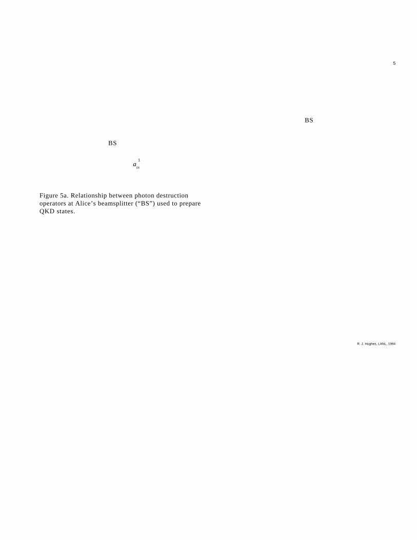
Figure 5a. Relationship between photon destruction operators at Alice’s
beamsplitter (“ BS” ) used to prepare QKD states.
Figure 5b. Relationship between photon destruction operators at Bob’s
beamsplitter (“ BS” ) used to measure QKD states.
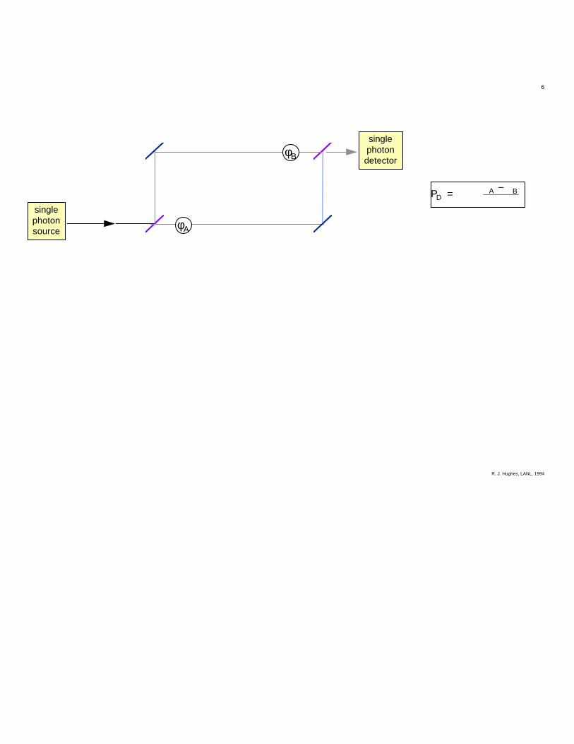
Figure 6. Realization of B92 QKD using single-photon interference in a Mach-
Zehnder interferometer built from beamsplitters (“ BS” ) and mirrors (“ M” ).
Alice has a source of single photons, one for each initial bit, and controls the
lower optical path length. Bob has a single-photon detector and controls the
upper optical path length according to the protocol described in the text. The
graph at right shows the probability that a photon is detected when Alice and
Bob have different bits (zero) and when they have the same bits (0.5). The
phase angles shown for the first four photons correspond to the bit values of
the example in Figure 4.
Figure 7. A time-multiplexed version of the interferometer of Figure 6 constructed
from two, smaller, unequal arm Mach-Zehnder interferometers. A single
photon is produced in a short wavepacket at the laser source “ L” at left and
detected at the detector “ D” at right. The photon has a 50% probability to exit
the first interferometer through the port that is linked to the second
interferometer. It will be in a coherent superposition of an amplitude to have

35
propagated via the “ short” path through the first interferometer, and a
temporally delayed amplitude corresponding to “ long” path propagation. Each
component is again split at the second interferometer, leading to three time-
separated windows in which the photon may arrive at the detector. Single-
photon interference occurs in the central time window between the “ short” -
” long” and “ long” -” short” propagation amplitudes, so that the photon
detection probability in this time window varies with the difference of the
adjustable phases φA and φB in each interferometer.
Figure 8. Schematic representation of the optical system for the Los Alamos QKD
prototype. The device is an all-fiber realization of the interferometer shown in
Figure 7.
Figure 9. Time-of-arrival spectrum of single photons propagating through the fiber
interferometer of Figure 8. The leftmost peak corresponds to photons that
traveled by both “ short” paths and the rightmost peak to those that took both
“ long” paths. The number of photons in the central peak varies with the
difference of the phases in each interferometer because of interference
between the “ short” -” long” and “ long” -” short” amplitudes.
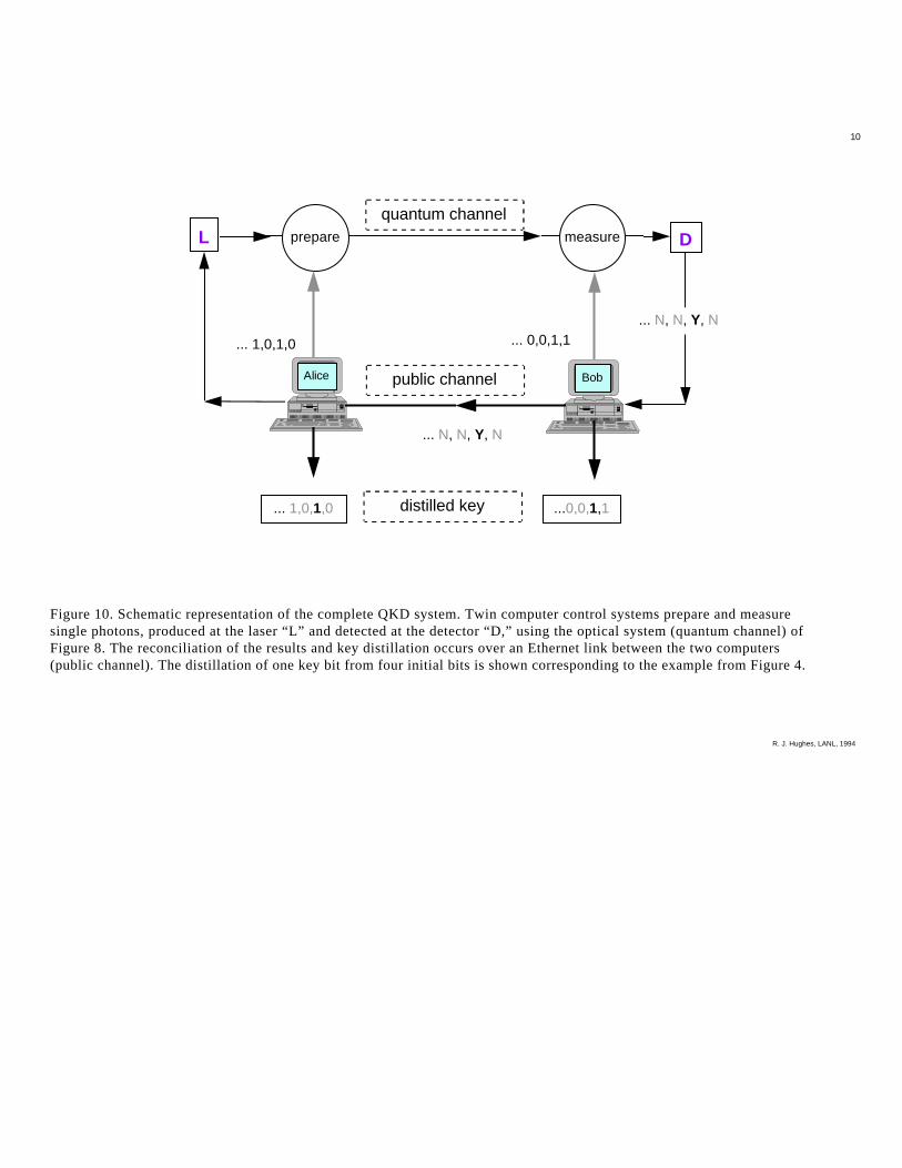
Figure 10. Schematic representation of the complete QKD system. Twin computer
control systems prepare and measure single photons, produced at the laser “ L”
and detected at the detector “ D ,” using the optical system (quantum channel)
of Figure 8. The reconciliation of the results and key distillation occurs over an
Ethernet link between the two computers (public channel). The distillation of
one key bit from four initial bits is shown corresponding to the example from
Figure 4.

R. J. Hughes, LANL, 1994
1
Figure 1. Sherlock Holmes’ “Dancing Men” which spell out the message “AM HERE ABE SLANEY.”
R. J. Hughes, LANL, 1994
3
keysource
Eve:enemy
cryptanalyst
message source
encryption decryption destinationopen channel
securechannel
keydistribution
keydistribution
Alice Bob
Figure 3. Key distribution in conventional cryptography.
R. J. Hughes, LANL, 1994
4
Step 4 : Alice and Bob retain only the “Y”bits: perfectly correlated subset
Step 1 : Alice & Bob generateindependent random bit sets
Alice 1 0 1 0 ...
Bob 0 0 1 1 ...
Step 2 : Alice sends Bob
Bob measures (projects)
"0" or "1"↔
R. J. Hughes, LANL, 1994
5
Figure 5a. Relationship between photon destructionoperators at Alice’s beamsplitter (“BS”) used to prepareQKD states.
BS
BS
ain
1
R. J. Hughes, LANL, 1994
6
φA
φB
singlephotonsource
singlephoton
detector
PDA B= −

R. J. Hughes, LANL, 1994
7
D
φΑ φΒ
L
Figure 7. A time-multiplexed version of the interferometer of Figure 7 constructed from two, smaller, unequal armMach-Zehnder interferometers. A single photon is produced in a short wavepacket at the laser source “L” at leftand detected at the detector “D” at right. The photon has a 50% probability to exit the first interferometer throughthe port that is linked to the second interferometer. It will be in a coherent superposition of an amplitude to havepropagated via the “short” path through the first interferometer, and a temporally delayed amplitude correspondingto “long” path propagation. Each component is again split at the second interferometer, leading to three time-separated windows in which the photon may arrive at the detector. Single-photon interference occurs in the centraltime window between the “short”-”long” and “long”-”short” propagation amplitudes, so that the photon detectionprobability in this time window varies with the difference of the adjustable phases φA and φB in each interferometer.

R. J. Hughes, LANL, 1994
8
φΒCooled
InGaAs APD detector
pulsed drive time-intervalanalyserstart stop
amplifiers &discriminators
PM fiber
φΑ1.3-µmpulsedlaser
attenuator
50/50 PMfiber couplers
electro-opticphase-shifter
air gap
“long” path∆T ~ 8.5 ns
Figure 8. Schematic representation of the optical system for the Los Alamos QKD prototype. The device is an all-fiberrealization of the interferometer shown in Figure 7.

R. J. Hughes, LANL, 1994
9
Figure 9. Time-of-arrival spectrum of single photonspropagating through the fiber interferometer of Figure 8.The leftmost peak corresponds to photons that travelled byboth “short” paths and the rightmost peak to those thattook both “long” paths. The number of photons in thecentral peak varies with the difference of the phases in eachinterferometer because of interference between the “short”-”long” and “long”-”short” amplitudes.
counts
relative arrival time
R. J. Hughes, LANL, 1994
10
measureL prepare D
... 1,0,1,0 ... 0,0,1,1
... N, N, Y, N
... N, N, Y, N
... 1,0,1,0 ...0,0,1,1
quantum channel
public channel
distilled key
BobAlice
Figure 10. Schematic representation of the complete QKD system. Twin computer control systems prepare and measuresingle photons, produced at the laser “L” and detected at the detector “D,” using the optical system (quantum channel) ofFigure 8. The reconciliation of the results and key distillation occurs over an Ethernet link between the two computers(public channel). The distillation of one key bit from four initial bits is shown corresponding to the example from Figure 4.


