Embed Size (px)
Citation preview
ULTRA-TECH Environmental Consultancy and Laboratory
M/S GANESH BENZOPLAST LIMITED
THE LIQUIED CHEMICAL STORAGE TERMINAL
QUANTITATIVE RISK ASSESSMENT
MAY 2018
WILLINGDON ISLAND
COCHIN, KERALA
PREPARED BY
RISK ANALYSIS
ULTRA-TECH Environmental Consultancy and Laboratory Page 1
To
Shri . Biju George
(Terminal Manager)
M/s Ganesh Benzoplast Limited
Liquid Chemical Storage Terminal
Plot No. A1, A2, A3,
Willingdon Island
Kochi, Kerala
Sub: Quantitative Risk Analysis Study Report of GBL LST Kochi
Dear Sir
We are pleased to submit two softcopy & hardcopy of the Risk Analysis Study Report and
We, on behalf of ULTRA-TECH Environmental Consultancy and Laboratory hereby take
the opportunity of cordially thanking the management and staff members for extending
earnest co- operation to successfully complete the Study.
We have immense pleasure in expressing our gratitude for entrusting us with the
responsibility of carrying out the Risk Analysis Study Report at your esteemed
Organization.
This association will be kept vivid in our record
Thanking you,
Yours faithfully,
S.DE.SARKAR
Page 2 ULTRA-TECH Environmental Consultancy and Laboratory
Contents
CHAPTER - 1: EXECUTIVE SUMMARY ................................................................................... 4
1.1 INTRODUCTION ............................................................................................................ 4
1.2 SCOPE OF THE STUDY ................................................................................................ 4
1.3 TERMINALS LOCATION.............................................................................................. 5
1.4 CLIMATE & METEOROLOGY..................................................................................... 5
1.5 TERMINAL PROFILE .................................................................................................... 5
1.6 UTILITIES ....................................................................................................................... 6
CHAPTER-2 : TERMINAL DETAILS.......................................................................................... 8
2.0 INTRODUCTION ............................................................................................................ 8
2.1 DESCRIPTION OF TERMINAL FACILITY ................................................................ 8
2.2 LOCATION, LAND AND LAYOUT ............................................................................ 8
2.4 PROCESS DESCRIPTION AND OPERATING PROCEDURES ................................. 9
2.5 TANK FARM: ................................................................................................................. 9
2.6 FIRE DETECTION AND PROTECTION SYSTEM ................................................... 11
CHAPTER-3 : RISK ANALYSIS ................................................................................................ 14
3.1 PREAMBLE................................................................................................................... 14
3.2 SCOPE OF THE STUDY .............................................................................................. 14
3.3 HAZARD IDENTIFICATION ...................................................................................... 15
3.4 CONSEQUENCE ANALYSIS ...................................................................................... 15
3.5 GLOSSARY OF TERMS USED IN RISK ASSESSMENT ......................................... 15
3.6 SCOPE OF STUDY ....................................................................................................... 16
CHAPTER-4 : HAZARD IDENTIFICATION ............................................................................ 18
4.1 INTRODUCTION .......................................................................................................... 18
4.2 CLASSIFICATION OF MAJOR HAZARDOUS SUBSTANCE ................................. 18
CHAPTER -5 : MAXIMUM CREDIBLE ACCIDENT ANALYSIS (MCAA) APPROACH .... 20
5.1 INTRODUCTION .......................................................................................................... 20
5.2 METHODOLOGY ......................................................................................................... 21
5.3 COMMON CAUSES OF ACCIDENTS........................................................................ 21
5.4 FAILURES OF HUMAN SYSTEMS............................................................................ 21
5.5 MAXIMUM CREDIBLE ACCIDENT ANALYSIS (MCAA) ..................................... 22
ANALYSIS OF PAST ACCIDENTS ...................................................................................... 23
5.7 HAZARDS OF EQUIPMENT/PIPELINE HANDLING PETROLEUM PRODUCTS
30
5.8 BRIEF REVIEW OF INBUILT DESIGN SAFETY ...................................................... 31
5.9 PRODUCT PIPELINE SYSTEMS ................................................................................ 32
5.10 PUMP HOUSE AT THE TERMINAL ...................................................................... 32
5.11 FIRE DETECTION AND PROTECTION SYSTEM ................................................ 32
5.13 PORTABLE FIRE FIGHTING APPARATUS .......................................................... 33
CHAPTER-6 : RISK ASSESSMENT .......................................................................................... 34
6.1 INTRODUCTION .......................................................................................................... 34
6.2 MODES OF FAILURE .................................................................................................. 35
6.3 DAMAGE CRITERIA..................................................................................................... 35
6.4 DISPERSION AND STABILITY CLASS ................................................................... 37
CHAPTER-7 : CONSEQUENCE ANALYSIS ............................................................................ 39
7.1 INTRODUCTION .......................................................................................................... 39

Page 3 ULTRA-TECH Environmental Consultancy and Laboratory
7.2.1 ALARP CONCEPT: ........................................................................................................ 40
7.2.2 EVENT TREE ANALYSIS & PROBABILITIES FOR THE RELEASE OF
DIFFERENT TYPES ................................................................................................................ 41
7.2.3 FREQUENCY ANALYIS .......................................................................................... 42
7.3 CONSIDERATION FOR MAXIMUM CREDIBLE ACCIDENT SCENARIO: ......... 44
HAZARD ASSESSMENT (QUANTIFICATION) .................................................................. 44
7.4 MODELING SOFTWARE ............................................................................................ 96
7.5 ACTION DURING FIRE............................................................................................... 96
CHAPTER-8 : RISKS AND FAILURE PROBABILITY............................................................ 99
CHAPTER-9 : RECOMMENDATIONS & CONCLUSIONS .................................................. 101

Page 4 ULTRA-TECH Environmental Consultancy and Laboratory
CHAPTER - 1: EXECUTIVE SUMMARY
1.1 INTRODUCTION
M/s Ganesh Benzoplast Limited vide Work Order No. …………dt……..entrusted
ULTRA-TECH Environmental Consultancy and Laboratory to carry out a ‘Risk
Analysis’ of their Liquid Chemical Storage Terminal (LST), Kochi. Our team of experts
had visited Kochi Terminal with a view to collecting relevant data of the plant. For the
purpose of obtaining specification of different onsite facilities, pipe lines, as well as off
site facilities, a detailed questionnaire was prepared. During visit of our team members,
they had collected the required information’s in the format. Pertinent documents like lay
out plan. P&I diagram, Mutual Aid agreement etc were collected from the Terminal. Our
team members along with the staffs of the plant had visited different parts of the
Terminal with a view to familiarize themselves with operation procedure, system of
working, location of different facilities as per the layout. Product handled, monthly
throughput etc. Besides operational aspect, the team was also apprised of the
organizational set up, existing system of handling Emergency Situation, available fire
fighting system.
ULTRA-TECH wants to put on record the excellent co operation they had received from
the officers and staff of the Terminal during entire course of their study. We extend our
thanks specially to Sri.. Biju George (Terminal Manager) for his excellent support in
making the information, documents available.
1.2 SCOPE OF THE STUDY
The risk assessment has been carried out in line with the requirements of various
statutory bodies:
Identification of potential hazard areas:
Identification of representative failure cases:
Identification of possible initiating events:
Assess the overall damage potential of the identified hazardous events and the
impact zones from the accidental scenarios:
Consequence analysis for all the possible events:
Hazard effect of LST

Page 5 ULTRA-TECH Environmental Consultancy and Laboratory
1.3 TERMINALS LOCATION
The Terminal is located at Sy No. 2578/4 at Willingdon Island in Thoppumpady Village,
Kochi Taluk, Eranakulam District, Kerala State.having latitude & longitude of 9o56’13.01”
N and 76o16’16.70” E respectively. The National Highway NH 966B is at a distance of
27m from the Terminal. A part of the Vembanad Lake is on the south west side.. The ATS
Willingdon Hotel is on the north side of the Terminal. IOC Petrol pump occupies the west
side as well as the east side of terminal.
1.4 CLIMATE & METEOROLOGY
The climate of Ernakulam district is mainly governed by the Arabian Sea and the
Western Ghats. Temperature ranges between 37°C to 16°C.. Relative humidity is 60% to
91%. The wind speed ranges from 5 to 6 km/hour with mean speed of 5.5 km/hour.
Annual Rainfall is around 2978 mm.
1.5 TERMINAL PROFILE
The Liquid Chemical Storage Terminal (LST) of GBL,Kochi was established at the
Cochin Port in May 2000, for providing storage for Petroleum Products of Class A, and
C and edible oils and non classified liquid products. Kochi LST caters to the needs of
bulk importers and exporters of liquid chemicals in India.
Kochi LST has three dedicated pipelines for transporting liquids directly from ship to
tank for imported items. The pipelines have a length of 3.2 km and transfers the liquid
chemicals from the Q4 Jetty in the Mattanchery Wharf at the Cochin Port to the LST. The
LST commenced operations with an initial capacity of 16,750 m3 (five Aboveground
Storage Tanks) and was utilised by BPCL for storage and marketing of Low Sulphur
Heavy Stock (LSHS) furnace oil which is a Class C Petroleum Product. Kochi LST also
has three Aboveground Storage Tanks of capacity 13500 m3 which is currently used for
the storage of Class ‘A’ Petroleum Products in bulk. Accordingly, the current storage
capacity of the LST is 30250 m3 and GBL is proposing to augment the storage capacity
of Kochi LST by addition of 4 aboveground storage tanks with aggregate capacity of
15,000 m3, which can be used for storage of Petroleum Products of Class A, B and C and

Page 6 ULTRA-TECH Environmental Consultancy and Laboratory
edible oils and non classified liquid products. The total capacity of Kochi LST after the
proposed expansion will be 45250 m3.
The main facilities are summarized as under:
Storage Existing 08 No’s Above Ground Tank
Proposed 04 No’s Above Ground Tank
TLF Gantry 4 bay gantry
DG Sets. 1 x 160 kVA
FIRE FIGHTING
FACILITIES
Fire Water Storage. 1 x 2750 KL
Jockey Pumps. 1 X 14 m3/hr.
Fire Water pumps. 1 x 60 m3/hr & 1 x 80 m3/hr
Control panel As per Standard
Storage Tank with active water
protection.
I. Fixed Roof tanks are fitted with sprinkler System
and foam system
II. Hydrants Monitors are provided at all strategic
point including TLF area, Tank farms, Pump House,
Tank Truck parking area, etc.
Fire extinguishers. As per OISD-117
Hydrants & Monitors. As per OISD-116
1.6 UTILITIES
Water requirement:-
Page 7 ULTRA-TECH Environmental Consultancy and Laboratory
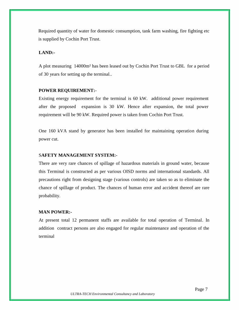
Required quantity of water for domestic consumption, tank farm washing, fire fighting etc
is supplied by Cochin Port Trust.
LAND:-
A plot measuring 14000m² has been leased out by Cochin Port Trust to GBL for a period
of 30 years for setting up the terminal..
POWER REQUIREMENT:-
Existing energy requirement for the terminal is 60 kW. additional power requirement
after the proposed expansion is 30 kW. Hence after expansion, the total power
requirement will be 90 kW. Required power is taken from Cochin Port Trust.
One 160 kVA stand by generator has been installed for maintaining operation during
power cut.
SAFETY MANAGEMENT SYSTEM:-
There are very rare chances of spillage of hazardous materials in ground water, because
this Terminal is constructed as per various OISD norms and international standards. All
precautions right from designing stage (various controls) are taken so as to eliminate the
chance of spillage of product. The chances of human error and accident thereof are rare
probability.
MAN POWER:-
At present total 12 permanent staffs are available for total operation of Terminal. In
addition contract persons are also engaged for regular maintenance and operation of the
terminal
Page 8 ULTRA-TECH Environmental Consultancy and Laboratory
CHAPTER-2 : TERMINAL DETAILS
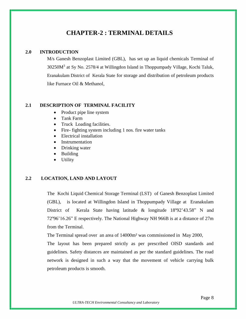
2.0 INTRODUCTION
M/s Ganesh Benzoplast Limited (GBL), has set up an liquid chemicals Terminal of
30250M3 at Sy No. 2578/4 at Willingdon Island in Thoppumpady Village, Kochi Taluk,
Eranakulam District of Kerala State for storage and distribution of petroleum products
like Furnace Oil & Methanol,
2.1 DESCRIPTION OF TERMINAL FACILITY
Product pipe line system
Tank Farm
Truck Loading facilities.
Fire- fighting system including 1 nos. fire water tanks
Electrical installation
Instrumentation
Drinking water
Building
Utility
2.2 LOCATION, LAND AND LAYOUT
The Kochi Liquid Chemical Storage Terminal (LST) of Ganesh Benzoplast Limited
(GBL), is located at Willingdon Island in Thoppumpady Village at Eranakulam
District of Kerala State having latitude & longitude 18o92’43.58” N and
72o96’16.26” E respectively. The National Highway NH 966B is at a distance of 27m
from the Terminal.
The Terminal spread over an area of 14000m² was commissioned in May 2000,
The layout has been prepared strictly as per prescribed OISD standards and
guidelines. Safety distances are maintained as per the standard guidelines. The road
network is designed in such a way that the movement of vehicle carrying bulk
petroleum products is smooth.
Page 9 ULTRA-TECH Environmental Consultancy and Laboratory
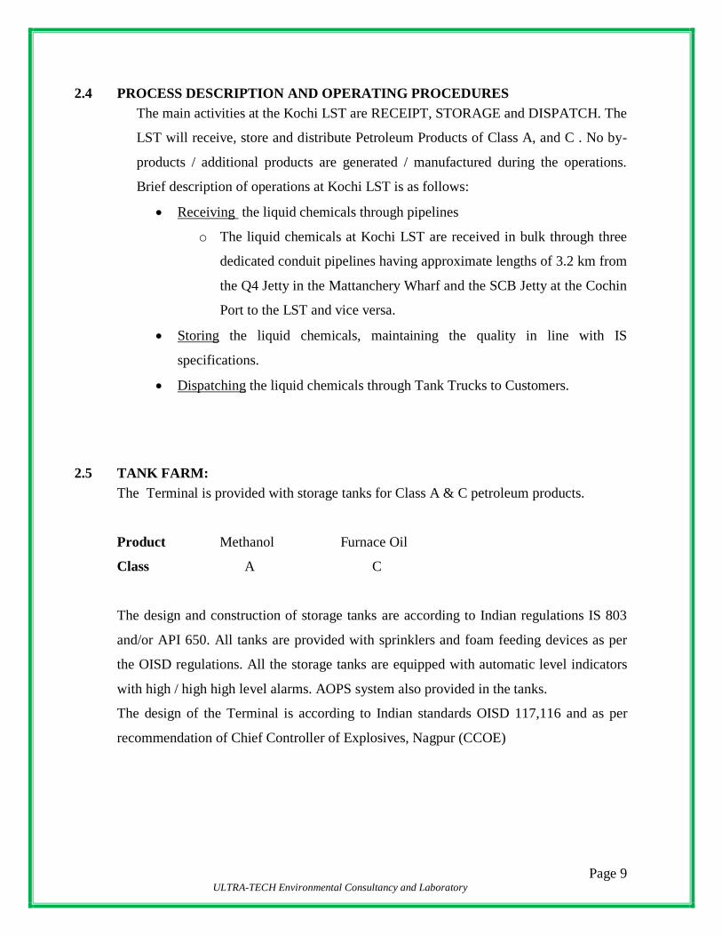
2.4 PROCESS DESCRIPTION AND OPERATING PROCEDURES
The main activities at the Kochi LST are RECEIPT, STORAGE and DISPATCH. The
LST will receive, store and distribute Petroleum Products of Class A, and C . No by-
products / additional products are generated / manufactured during the operations.
Brief description of operations at Kochi LST is as follows:
Receiving the liquid chemicals through pipelines
o The liquid chemicals at Kochi LST are received in bulk through three
dedicated conduit pipelines having approximate lengths of 3.2 km from
the Q4 Jetty in the Mattanchery Wharf and the SCB Jetty at the Cochin
Port to the LST and vice versa.
Storing the liquid chemicals, maintaining the quality in line with IS
specifications.
Dispatching the liquid chemicals through Tank Trucks to Customers.
2.5 TANK FARM:
The Terminal is provided with storage tanks for Class A & C petroleum products.
Product Methanol Furnace Oil
Class A C
The design and construction of storage tanks are according to Indian regulations IS 803
and/or API 650. All tanks are provided with sprinklers and foam feeding devices as per
the OISD regulations. All the storage tanks are equipped with automatic level indicators
with high / high high level alarms. AOPS system also provided in the tanks.
The design of the Terminal is according to Indian standards OISD 117,116 and as per
recommendation of Chief Controller of Explosives, Nagpur (CCOE)
Page 10 ULTRA-TECH Environmental Consultancy and Laboratory
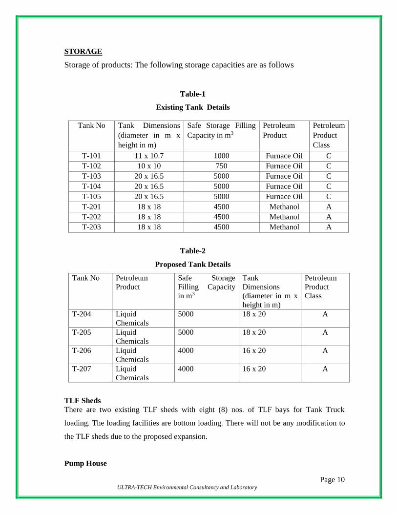
STORAGE
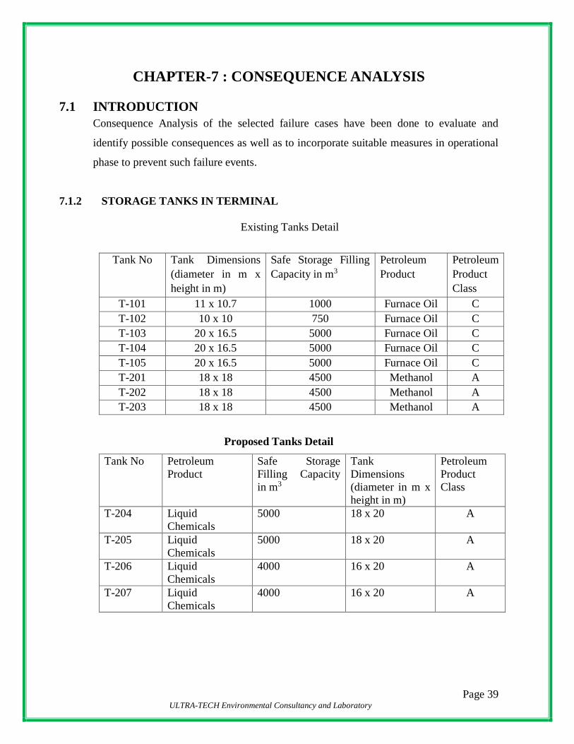
Storage of products: The following storage capacities are as follows
Table-1
Existing Tank Details
Tank No Tank Dimensions
(diameter in m x
height in m)
Safe Storage Filling
Capacity in m3
Petroleum
Product
Petroleum
Product
Class
T-101 11 x 10.7 1000 Furnace Oil C
T-102 10 x 10 750 Furnace Oil C
T-103 20 x 16.5 5000 Furnace Oil C
T-104 20 x 16.5 5000 Furnace Oil C
T-105 20 x 16.5 5000 Furnace Oil C
T-201 18 x 18 4500 Methanol A
T-202 18 x 18 4500 Methanol A
T-203 18 x 18 4500 Methanol A
Table-2
Proposed Tank Details
Tank No Petroleum
Product
Safe Storage
Filling Capacity
in m3
Tank
Dimensions
(diameter in m x
height in m)
Petroleum
Product
Class
T-204 Liquid
Chemicals
5000 18 x 20 A
T-205 Liquid
Chemicals
5000 18 x 20 A
T-206 Liquid
Chemicals
4000 16 x 20 A
T-207 Liquid
Chemicals
4000 16 x 20 A
TLF Sheds
There are two existing TLF sheds with eight (8) nos. of TLF bays for Tank Truck
loading. The loading facilities are bottom loading. There will not be any modification to
the TLF sheds due to the proposed expansion.
Pump House
Page 11 ULTRA-TECH Environmental Consultancy and Laboratory
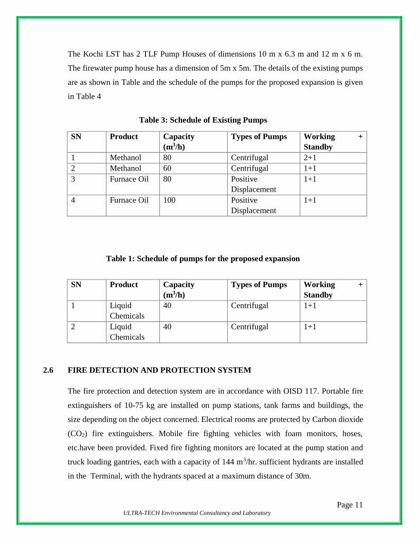
The Kochi LST has 2 TLF Pump Houses of dimensions 10 m x 6.3 m and 12 m x 6 m.
The firewater pump house has a dimension of 5m x 5m. The details of the existing pumps
are as shown in Table and the schedule of the pumps for the proposed expansion is given
in Table 4
Table 3: Schedule of Existing Pumps
SN Product Capacity
(m3/h)
Types of Pumps Working +
Standby
1 Methanol 80 Centrifugal 2+1
2 Methanol 60 Centrifugal 1+1
3 Furnace Oil 80 Positive
Displacement
1+1
4 Furnace Oil 100 Positive
Displacement
1+1
Table 1: Schedule of pumps for the proposed expansion
SN Product Capacity
(m3/h)
Types of Pumps Working +
Standby
1 Liquid
Chemicals
40 Centrifugal 1+1
2 Liquid
Chemicals
40 Centrifugal 1+1
2.6 FIRE DETECTION AND PROTECTION SYSTEM
The fire protection and detection system are in accordance with OISD 117. Portable fire
extinguishers of 10-75 kg are installed on pump stations, tank farms and buildings, the
size depending on the object concerned. Electrical rooms are protected by Carbon dioxide
(CO2) fire extinguishers. Mobile fire fighting vehicles with foam monitors, hoses,
etc.have been provided. Fixed fire fighting monitors are located at the pump station and
truck loading gantries, each with a capacity of 144 m3/hr. sufficient hydrants are installed
in the Terminal, with the hydrants spaced at a maximum distance of 30m.

Page 12 ULTRA-TECH Environmental Consultancy and Laboratory
The tanks are equipped with fixed cooling water and foam Terminals and mobile vehicles and
equipment (monitors, hoses, branch pipes, etc.) are provided to handle field fires.
Table below will show fire water storage tank, fire water pumps,
Table-5
Fire Water Storage Tank
Sr.No No’s Total Capacity (KL)
1 1 2750
Table-6
Fire Water Pump
Sr.No Category No’s Capacity
1
Main Pump
( Engine Driven)
2
60 M3/Hr & 80 M3/Hr
2 Jockey Pump
( Electric Motor
Driven)
1 14 M3/Hr
FIRE ALARM SYSTEM
Conventional type Fire alarm systems are provided in following areas;
a) Truck Loading
b) Tank Farm
c) Office / Admn. Building
d) Sub-Stations
Source of Signaling
The source of signaling is considered as ESD These are considered for the areas
where manual warning is to be initiated on notice of fire. They are mostly provided

Page 13 ULTRA-TECH Environmental Consultancy and Laboratory
for open areas or near to access doors, truck loading, pump house, tank farm,
administrative building, etc.
ELECTRICAL SYSTEM
The scope covers the basic concepts of the following:
Receiving of HT Power supply from Main 11kV Power Grid
Distribution Transformer.
Distribution of LT power supply.
Cabling System.
Building and Area Lighting.
Approach Road Lighting
Earthing and Lightning Protection.
Power Factor Improvement.
Battery Bank & Battery Charger.
UPS system.
Diesel Generating Set.
Cylindrical Bullet
of 150 MT

Page 14 ULTRA-TECH Environmental Consultancy and Laboratory
CHAPTER-3 : RISK ANALYSIS
3.1 PREAMBLE
With growth of population, industrialization, urbanization and modernization, demand of
petroleum products are increasing at a very rapid pace. With a view to meeting demand
of industry, capacity addition has become essential.
As the Terminal handle various petroleum products which have got potential of fire /
explosion hazard for itself, hence it is necessary to evaluate the Risk due to the Terminal.
Accordingly, M/s. ULTRA-TECH Environmental Consultancy & Laboratory. (ULTRA-
TECH) has been retained by Ganesh Benzoplast Limited (GBL), as consultant to carryout
Risk Analysis Study for the Kochi LST.
3.2 SCOPE OF THE STUDY
The risk assessment has been carried out in line with the requirements of various
statutory bodies:
Identification of potential hazard areas;
Identification of representative failure cases;
Identification of possible initiating events;
Assess the overall damage potential of the identified hazardous events and the
impact zones from the accidental scenarios;
Consequence analysis for all the possible events;

Page 15 ULTRA-TECH Environmental Consultancy and Laboratory
3.3 HAZARD IDENTIFICATION
Identify potentially hazardous materials that can cause loss of human life/injury,
loss of properties and deterioration of the environment due to loss of containment.
Identify potential scenarios, which can cause loss of containment and consequent
hazards like fire, explosion and toxicity.
3.4 CONSEQUENCE ANALYSIS
Analysis of magnitude of consequences of different potential hazard scenarios and
their effect zones.
Consequence analysis is a measure of potential hazards and is important for
taking precautionary measures for risk reduction as well as mitigation of effect in
case of such accidents happening.
This report has been prepared by applying the standard techniques of risk assessment and
the information provided by GBL.
3.5 GLOSSARY OF TERMS USED IN RISK ASSESSMENT
The common terms used in Risk Assessment and Disaster Management are elaborated
below:
“Risk” is defined as a likelihood of an undesired event (accident, injury or death)
occurring within a specified period or under specified circumstances. This may be either
a frequency or a probability depending on the circumstances.
“Hazard” is defined as a physical situation, which may cause human injury, damage to
property or the environment or some combination of these criteria.
“Hazardous Substance” means any substance or preparation, which by reason of its
chemical or physico-chemical properties or handling is liable to cause harm to human
beings, other living creatures, plants, micro-organisms, property or the environment.
Page 16 ULTRA-TECH Environmental Consultancy and Laboratory
“Hazardous Process” is defined as any process or activity in relation to an industry,
which may cause impairment to the health of the persons engaged or connected therewith
or which may result in pollution of general environment.
“Disaster” is defined as a catastrophic situation that causes damage, economic
disruptions, loss of human life and deterioration of health and health services on a scale
sufficient to warrant an extraordinary response from outside the affected area or
community. Disaster occasioned by man is factory fire explosions and release of toxic
gases or chemical substances etc.
“Accident” is an unplanned event, which has a probability of causing personal injury or
property damage or both.
“Emergency” is defined as a situation where the demand exceeds the resources. This
highlights the tropical nature of emergency “It is seen after experience that enough is not
enough in emergency situations. Situations of this nature are avoidable but it is not
possible to avoid them always.” “Emergency Preparedness” is one of the key activities in
the overall management. Preparedness, though largely dependent upon the response
capacity of the persons engaged in direct action, will require support from others in the
organization before, during and after an emergency.
3.6 SCOPE OF STUDY
The risk assessment has been carried out in line with the requirements of various
statutory bodies for similar type of projects:
Identification of potential hazard areas
Identification of representative failure cases
Identification of possible initiating events
Assess the overall damage potential of the identified hazardous events and the
impact zones from the accidental scenarios;
Consequence analysis for all the possible events;
Furnish specific recommendations on the minimization of the worst accident
possibilities.

Page 17 ULTRA-TECH Environmental Consultancy and Laboratory
Table-7
FLOW CHART FOR RISK ANALYSIS STUDY
YES
START
PLANT VISIT
DATA COLLECTION
PROCESS DESCRIPTION
PROCESS CONTROL LOOPS
PRI/PFD OPERATING
MANUAL START UP/SHUT DOWN
PLOT PLAN
METEOROLOGICAL DATA
PAST ACCIDENTS DATA
ALL RELEVANT PHYSICAL
CHEMICAL DATA OF
CHEMICALS INV0LVED
SELECT THE
CLASSIFY VESSEL/EQUIPMENT
INVENTORY ANALYSIS
CALCULATE EFFECT
IDENTIFICATION OF HAZARD
IS FE/FET IN
SEVERITY ADOPT CHECK LIST
APPROACH
CONSEQUENCE
PLOT DAMAGE DISTANCE
Page 18 ULTRA-TECH Environmental Consultancy and Laboratory
CHAPTER-4 : HAZARD IDENTIFICATION
4.1 INTRODUCTION
Identification of hazards in the terminal is of primary significance in the analysis,
quantification and cost effective control of accidents involving chemicals and process. A
classical definition of hazard states that hazard is in fact the characteristic of
system/plant/process that presents potential for an accident. Hence, all the components of
a system/plant/process need to be thoroughly examined to assess their potential for
initiating or propagating an unplanned event/sequence of events, which can be termed as
an accident.
Typical schemes of predictive hazard evaluation and quantitative risk analysis suggest
that hazard identification step plays a key role.
Estimation of probability of an unexpected event and its consequence form the basis of
quantification of risk in terms of damage to property, environment or personnel.
Therefore, the type, quantity, location and conditions of release of a toxic or flammable
substance have to be identified in order to estimate its damaging effects, the area
involved and the possible precautionary measures required to be taken. The following
two methods for hazard identification have been employed in the study.
Identification of hazardous storage units based on relative ranking technique, viz,
Fire-Explosion and Toxicity index (FE & TI); and
Maximum Credible Accident Analysis (MCAA)
4.2 CLASSIFICATION OF MAJOR HAZARDOUS SUBSTANCE

Page 19 ULTRA-TECH Environmental Consultancy and Laboratory
Hazardous substances may be classified into three main classes namely flammable
substances, unstable substances and toxic substances.
Flammable substances require interaction with air for their hazard to be realized; under
certain circumstances vapours arising from flammable substances when mixed with air
may be explosive especially in confined spaces. However, if present in sufficient quantity
such clouds may explode in open air also.
Unstable substances are liquids or solids, which may decompose with such violence so as
to give rise to blast waves.
Finally, toxic substances are dangerous and cause substantial damage to life when
released into the atmosphere. The ratings for a large number of chemicals based on
flammability, reactivity and toxicity are given NFPA Codes 49 and 345M.

Page 20 ULTRA-TECH Environmental Consultancy and Laboratory
CHAPTER -5 : MAXIMUM CREDIBLE ACCIDENT ANALYSIS
(MCAA) APPROACH
5.1 INTRODUCTION
A Maximum Credible Accident (MCA) can be characterized, as an accident with a
maximum damage potential, which is still believed to be probable.
MCA analysis does not include quantification of probability of occurrence of an accident.
Moreover, since it is not possible to indicate exactly a level of probability that is still
believed to be credible, selection of MCA is somewhat arbitrary. In practice, selection of
accident scenarios representative for a MCA-Analysis is done on the basis of engineering
judgment and expertise in the field of risk analysis studies, especially accident analysis.
Major hazards posed by flammable storage can be identified taking recourse to MCA
analysis. This encompasses certain techniques to identify the hazards and calculate the
consequent effects in terms of damage distances of heat radiation, toxic releases, vapour
cloud explosion etc. A host of probable or potential accidents of the major units in the
complex arising due to use, storage and handling of the hazardous materials are examined
to establish their credibility. Depending upon the effective hazardous attributes and their
impact on the event, the maximum effect on the surrounding environment and the
respective damage caused can be assessed.
As an initial step in this study, a selection has been made of the processing and storage
units and activities, which are believed to represent the highest level of risk for the
surroundings in terms of damage distances. For this selection, following factors have
been taken into account:
Type of compound viz. flammable or toxic
Quantity of material present in a unit or involved in an activity and
Process or storage conditions such as temperature, pressure, flow, mixing and presence of incompatible material.
In addition to the above factors, location of a unit or activity with respect to adjacent
activities is taken into consideration to account for the potential escalation of an accident.

Page 21 ULTRA-TECH Environmental Consultancy and Laboratory
This phenomenon is known as the Domino Effect. The units and activities, which have
been selected on the basis of the above factors, are summarized, accident scenarios are
established in hazard identification studies, whose effect and damage calculations are
carried out in Maximum Credible Accident Analysis Studies.
5.2 METHODOLOGY
Following steps are employed for visualization of MCA scenarios:
Chemical inventory analysis
Identification of chemical release and accident scenarios
Analysis of past accidents of similar nature to establish credibility to identified scenarios; and
Short-listing of MCA scenarios
5.3 COMMON CAUSES OF ACCIDENTS
Based on the analysis of past accident information, common causes of accidents are
identified as:
Poor house keeping
Improper use of tools, equipment, facilities
Unsafe or defective equipment facilities
Lack of proper procedures
Improvising unsafe procedures
Failure to follow prescribed procedures
Jobs not understood
Lack of awareness of hazards involved
Lack of proper tools, equipment, facilities
Lack of guides and safety devices, and
Lack of protective equipment and clothing
5.4 FAILURES OF HUMAN SYSTEMS
An assessment of past accidents reveal human factor to be the cause for over 60% of the
accidents while the rest are due to other component failures. This percentage will increase

Page 22 ULTRA-TECH Environmental Consultancy and Laboratory
if major accidents alone are considered for analysis. Major causes of human failures
reported are due to:
Stress induced by poor equipment design, unfavorable environmental conditions, fatigue, etc.
Lack of training in safety and loss prevention
Indecision in critical situation; and
Inexperienced staff being employed in hazardous situation
Often, human errors are not analyzed while accident reporting and accident reports only
provide information about equipment and/or component failures. Hence, a great deal of
uncertainty surrounds analysis of failure of human systems and consequent damages.
5.5 MAXIMUM CREDIBLE ACCIDENT ANALYSIS (MCAA)
Hazardous substances may be released as a result of failures or catastrophes, causing
possible damage to the surrounding area. This section deals with the question of how the
consequences of release of such substances and the damage to surrounding area can be
determined by means of models.
It is intended to give an insight into how the physical effects resulting from release of
hazardous substances can be calculated by means of models and how vulnerability
models can be used to translate the physical effects in terms of injuries and damage to
exposed population and environment. A disastrous situation in general is due to outcome
of fire, Vapour Cloud explosion or toxic hazards in addition to other natural causes,
which eventually lead to loss of life, property and ecological imbalance.
Major hazards posed by flammable storage can be identified taking recourse to MCA
analysis. MCA analysis encompasses certain techniques to identity the hazards and
calculate the consequent effect in terms of damage distances of heat radiation, toxic
release, vapour cloud explosion etc. A host of probable or potential accidents of the major
units in the complex arising due to use, storage and handling of the hazardous materials
are examined to establish their credibility. Depending upon the effective hazardous
attributes and their impact on the event, the maximum effect on the surrounding

Page 23 ULTRA-TECH Environmental Consultancy and Laboratory
environment and the respective damage caused can be assessed. The MCA analysis
involves ordering and ranking various sections in terms of potential vulnerability.
ANALYSIS OF PAST ACCIDENTS
Numerous accidents involving different hydrocarbons in process plants have been
reported. Table 9 provides a world wide list of all such accidents reported since 1917.
More than 1000 people have received injuries of various intensity and more than 200
people died due to these accidents. The major causes of accident involving fraction are
given below.
i) Fire, over pressure, explosions 19 Nos
ii) Overfilling, loading/unloading and pipeline ruptures 5 Nos
iii) Collision and impact of rail/road tankers during transportation 21 Nos
---
45 Nos
It can be seen that the storage areas and transportation vehicles of C fractions are most
vulnerable to accidents. More than 10 accidents out of the 45 incidents examined have
ended in BLEVE situation. Rest of them has caused fires and explosions.
The consequences of BLEVE have been found to be most severe in the vicinity of the
accident site. The worst disaster of C fraction had occurred in November 1984 at the C
fractions storage and distribution center in San Juan Ixhautepec in Mexico City. An
extensive fire and a series of violent explosions resulted in chaos.
TABLE – 8
MAJOR ACCIDENT IN PROCESS INDUSTRIES
(LIGHTER FRACTIONS OF HYDROCARBONS)
Sl.
No.
Year Location Chemical Event Deaths/Injuries
01 1944 Cleveland, Ohio Gasoline Fire & Explosion 128 D, 200-400 I
02 1949 Perth, NJ Hydrocarbon Fire 4 D
03 1955 Whiting, Ind. Naphtha Explosion 2 D, 30 I

Page 24 ULTRA-TECH Environmental Consultancy and Laboratory
04 1956 New York, USA Ehylene -- --
05 1958 Signal Hill, California Oil Forth Fire 2 D
06 1962 Ras Tanura, Saudi Arabia Propane Fire 1 D, 114 I
07 1963 Rexas, USA Polypropylene Explosion -
08 1964 Fackass Flats, Mev. Hydrogen Explosion -
09 1966 Feyzin, France Propane Fire & Explosion 18 D, 81 I
10 1966 Larose, La NGL Fire (on pipeline) 7 D
11 1966 W. Germany Methane Explosive (failure of
pipe)
3 D, 83 I
12 1967 Buenos Aires Propane -- --
13 1968 Pernis, Netherlands Oil slopes Explosion 9 D, 85 I
14 1968 Terrylown, USA Propane -- --
15 1968 Kennedale, Texac Gasoline Explosion (on road
tnkers)
28 I
16 1969 Pnerts la Cruz Light Hydrocarbon Explosion 5 D
17 1970 Liden Niji Oil Refinery Fire --
18 1970 Port Hudson, MO Propane Explosion (on pipeline) --
19 1970 Mont Belview, Tex Butane Explosion (on pipeline) --
20 1971 Longview, Tex Ethylene Explosion 4 D, 60 I
21 1972 Hearne, Tex Crude Oil Fire & Explosion 1 D, 2 I
22 1972 Lynchbriod Va Propane Fire & explosion 1 D, 2 I
23 1972 Netherlands Hydrogen Explosion 4 D, 4 I,
24 1972 New Jersey, Turnpike,
New Jersey
Propane Explosion (on road
tanker)
2 D
25 1972 Brazil Butane Explosion UVCE 37 D, 53 I
26 1972 Billings, Mont. Butane Explosion 4 I
27 1973 St. Amandles-Eaux France Propane Explosion (on road
tanker)
5 D, 40 I
28 1973 Staten Island, NY Gasoline Fire (in empty storage
tank)
40 D
Sl.
No
.
Year Location Chemical Event Deaths/Injuries
29 1974 Decatur, III Propane Explosion (on
railway)
7 D, 152 I
30 1974 Florida, USA Propane Explosion --
31 1974 Griffith Ind. Propane Fire --
32 1974 India Crude Oil Explosion --
33 1974 Czechoslovakia Ethylene Explosion UVCE 14 D, 79 I,
34 1974 Mississippi, Butane Explosion UVCE 24 I,
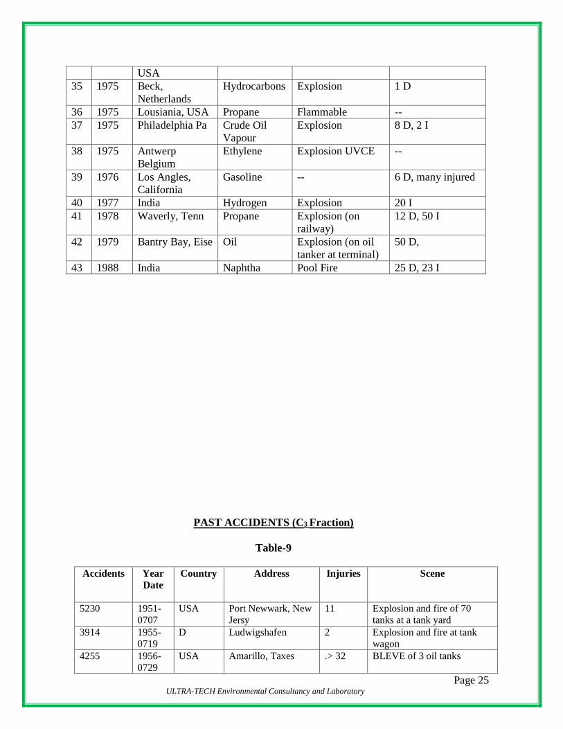
Page 25 ULTRA-TECH Environmental Consultancy and Laboratory
USA
35 1975 Beck,
Netherlands
Hydrocarbons Explosion 1 D
36 1975 Lousiania, USA Propane Flammable --
37 1975 Philadelphia Pa Crude Oil
Vapour
Explosion 8 D, 2 I
38 1975 Antwerp
Belgium
Ethylene Explosion UVCE --
39 1976 Los Angles,
California
Gasoline -- 6 D, many injured
40 1977 India Hydrogen Explosion 20 I
41 1978 Waverly, Tenn Propane Explosion (on
railway)
12 D, 50 I
42 1979 Bantry Bay, Eise Oil Explosion (on oil
tanker at terminal)
50 D,
43 1988 India Naphtha Pool Fire 25 D, 23 I
PAST ACCIDENTS (C3 Fraction)
Table-9
Accidents Year
Date
Country Address Injuries Scene
5230 1951-
0707
USA Port Newwark, New
Jersy
11 Explosion and fire of 70
tanks at a tank yard
3914 1955-
0719
D Ludwigshafen 2 Explosion and fire at tank
wagon
4255 1956-
0729
USA Amarillo, Taxes .> 32 BLEVE of 3 oil tanks
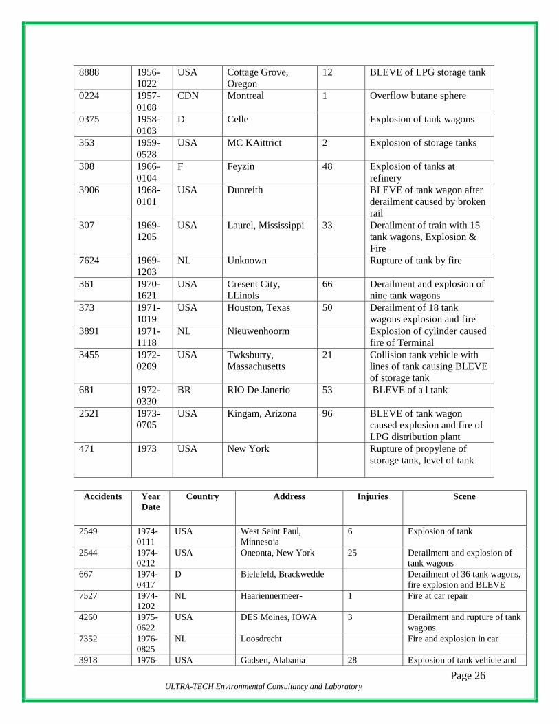
Page 26 ULTRA-TECH Environmental Consultancy and Laboratory
8888 1956-
1022
USA Cottage Grove,
Oregon
12 BLEVE of LPG storage tank
0224 1957-
0108
CDN Montreal 1 Overflow butane sphere
0375 1958-
0103
D Celle Explosion of tank wagons
353 1959-
0528
USA MC KAittrict 2 Explosion of storage tanks
308 1966-
0104
F Feyzin 48 Explosion of tanks at
refinery
3906 1968-
0101
USA Dunreith BLEVE of tank wagon after
derailment caused by broken
rail
307 1969-
1205
USA Laurel, Mississippi 33 Derailment of train with 15
tank wagons, Explosion &
Fire
7624 1969-
1203
NL Unknown Rupture of tank by fire
361 1970-
1621
USA Cresent City,
LLinols
66 Derailment and explosion of
nine tank wagons
373 1971-
1019
USA Houston, Texas 50 Derailment of 18 tank
wagons explosion and fire
3891 1971-
1118
NL Nieuwenhoorm Explosion of cylinder caused
fire of Terminal
3455 1972-
0209
USA Twksburry,
Massachusetts
21 Collision tank vehicle with
lines of tank causing BLEVE
of storage tank
681 1972-
0330
BR RIO De Janerio 53 BLEVE of a l tank
2521 1973-
0705
USA Kingam, Arizona 96 BLEVE of tank wagon
caused explosion and fire of
LPG distribution plant
471 1973 USA New York Rupture of propylene of
storage tank, level of tank
Accidents Year
Date
Country Address Injuries Scene
2549 1974-
0111
USA West Saint Paul,
Minnesoia
6 Explosion of tank
2544 1974-
0212
USA Oneonta, New York 25 Derailment and explosion of
tank wagons
667 1974-
0417
D Bielefeld, Brackwedde Derailment of 36 tank wagons,
fire explosion and BLEVE
7527 1974-
1202
NL Haariennermeer- 1 Fire at car repair
4260 1975-
0622
USA DES Moines, IOWA 3 Derailment and rupture of tank
wagons
7352 1976-
0825
NL Loosdrecht Fire and explosion in car
3918 1976- USA Gadsen, Alabama 28 Explosion of tank vehicle and
Page 27 ULTRA-TECH Environmental Consultancy and Laboratory
0831 storage tanks during
transipment
2071 1976-
1126
USA Belt, Montana 22 Derailment and explosion of
several tank wagons
4137 1977-
0206
USA Boynton Beach, Florida BLEVE of LPG cylinders
caused by derailment freight
train
669 1977-
0220
USA Dallas, Taxas 1 Derailment of tank wagons
4235 1977-
0423
USA Long Island, New York 1 BLEVE cylinders on lorry
3377 1977-
0519
USA Hawley, Pennsylvania Fire and BLEVE of tank on
tar
2522 1977-
0519
USA Pocono Mountains
Pennsylvania
1 Leakage supply line caused
explosion vans
618 1978-
0222
USA Waverly, jernessee 43 Derailment of several tank
wagons caused by broken
wheel
2119 1978-
0530
USA Texas City, Texas 10 11 tank explored by unknown
cause in 45 minutes
209 1978-
1218
NL NIJMEGEN BLEVE of tank vehicle at fuel
station during transshipment
2736 1978-
1218
NL Zwolle 6 Explosion of gas cylinder in
measure car
1591 1979-
0549
NL Vlaardingen 2 Fire in van and explosion of
gas cylinder
1639 1979-
0601
NL S. Gravenzande 2 Explosion of gas cylinder
during fire in barn
1634 1979-
0704
NL Ostflakgee Explosion of two cylinders
and one oil tank
Accidents Year
Date
Country Address Injuries Scene
2575 1979-
0713
NL Rotterdam Explosion of cylinder in
van
1630 1979-
0817
NL De MEEM Overheating of kettle with
tar caused explosion of gas
cylinder
953 1979-
0908
USA Pakton, Taxas 8 Derailment of 33 train
wagons with chemicals,
explosion and fire for 2.5
days
1568 1979-
1203
NL Haarlemmermeer Explosion of tank in car
1181 1980-
0105
NL Rotterdam 1 Fire in bus station, LPG
tank explored
1166 1980-
0108
NL Eriecom, River Waa 2 Collision of tanker “Kombi
21” and vessel “Rodort 6”
explosion, fire
3922 1980- USA Los Angles, California 2 Overturn and explosion of

Page 28 ULTRA-TECH Environmental Consultancy and Laboratory
0303 tank vehicle loaded with gasoline
0706 1980-
0606
NL Rotterdam Fire in factory store
2701 1980-
0804
NL RAAITE Fire in motor compartment
of car, BLEVE of tank
0919 1980 NL Road Breeda to
BAVEL
Mobile milling machine
with gas tank explored
1520 1980-
1125
NL OOSTERMOLDGE 1 Explosion of tank in car
during assemble
3419 1980 D Kries Borken Weseko 2 Fire and explosion of tank
vehicle
1836 1981-
0302
NL Weirden Fire and explosion of gas
cylinders in stored caravans
2052 1981-
0409
NL Apeldoorn Fire of carabans near LPG
Terminal
2092 1981-
0510
NL Haarlem Fire and explosion of
storage Barn
2504 1981-
0713
NL Beuwingen 1 Explosion of gas cylinder in
house
2561 1981-
0816
NL Oldeholtrade,
Wolvega
1 Explosion of gas tank in car
by collision
3988 1981 NL Tiel 1 VW Transporter on fire,
tank exploded
4350 1981 USA Unknown 17 BLEVE of cylinder in
converted coach
5535 1981 6B Yately, Hahpshire Explosion of car tank in
garage
7640 1982-
0113
NL Alkmaar Fire and rupture of cylinder
explosion of a plumber gas
3949 1982-
0525
NL Den hag Cylinder
3960 1982-
0601
NL Haarklem Explosion of a cylinder in
car
Accidents Year
Date
Country Address Injuries Scene
3972 1982-
0621
NL Grootbroek 1 Cycling person hit fatally
by fragment of cylinder
4054 1982-
0626
CDN Blairmore, Alberta Derailment and rupture of
several tank wagons
7642 1982-
0916
NL Unknown Rupture of gas tank in car
by overspeed
5681 1982-
0928
USA Livingston, Louisiana Derailment freightain by
overspeed
4449 1982 ET SUEZ 19 Fire and explosion of gas
pipeline

Page 29 ULTRA-TECH Environmental Consultancy and Laboratory
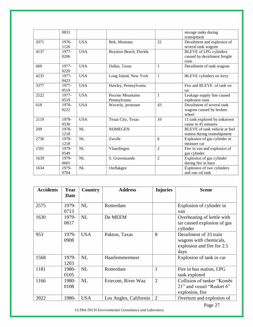
8227 1984-0315
NL Unknown Plastic deformation of tank due to overtheating by fire
8228 1984-
0709
NL Rosmalen Rupture of a car link due to
fire
7942 1984-
0723
USA Romeoville and
lemont
22 Explosion and fire at
refinery llinois
8235 1984-
0921
NL Bruchterveld,
Hardenberg
Rupture of cylinder
RELEASE OF HAZARDOUS SUBSTANCE
POOL
VAPOUR
FLASH
IGNITION
FIRE
YES
CONTINUOUS
IGNITION
DISPERSION
VAPOUR CLOUD
EXPLOSION
PRESSURE WAVE
HEAT RADIATIONN
EFFECTS

Page 30 ULTRA-TECH Environmental Consultancy and Laboratory
5.7 HAZARDS OF EQUIPMENT/PIPELINE HANDLING PETROLEUM
PRODUCTS
The hazard of equipment/pipeline handling petroleum products is the potential loss of
integrity of the containment with subsequent release of liquid causing fire. The pipelines
carry large quantities of petroleum liquid. A rare pipeline fracture would release large
quantities of hydrocarbons. The products would get collected in the neighbourhood of the
pipeline and may lead to a fire hazard if it gets source of ignition and proper precautions
are not taken.
Catastrophic failures of the shell of a storage tank are very rare phenomenon, which may
occur due to earthquake or due to aerial bombardment during war. However, vapour
coming out through the vent line of fixed roof tank or through vapour seal round the shell
in floating roof tanks may be ignited through lighting. However, such cases are also very
rare. In such cases the whole tank may be on fire. Corrosion in the tanks may cause small
holes causing release of petroleum liquid from the tanks. However, in such cases the oil
will be contained in the dyke. In case of oil spill collected on ground an oil pool will be
formed. An ignited pool of oil is called Pool Fire. It creates long smoky flames. The wind
may tilt the flame towards ground causing secondary fires and damages. Radiation from
the flame can be very intense near the fire but falls of rapidly beyond 3-4 pool diameters.
Such fires are very destructive within the plant area and near the source of generation.
In case of formation of holes on the above ground pipeline the liquid may escape in the
form of jet and may catch fire if it gets an ignition source. Damage due to heat radiation
from such jets is mostly limited to objects in the path. However, the ignited jet can
impinge on other vessels and the pipelines causing domino effect.
Page 31 ULTRA-TECH Environmental Consultancy and Laboratory
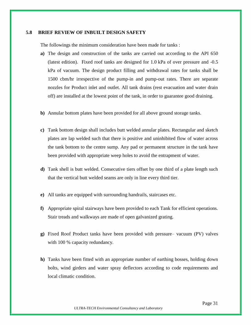
5.8 BRIEF REVIEW OF INBUILT DESIGN SAFETY
The followings the minimum consideration have been made for tanks :
a) The design and construction of the tanks are carried out according to the API 650
(latest edition). Fixed roof tanks are designed for 1.0 kPa of over pressure and -0.5
kPa of vacuum. The design product filling and withdrawal rates for tanks shall be
1500 cbm/hr irrespective of the pump-in and pump-out rates. There are separate
nozzles for Product inlet and outlet. All tank drains (rest evacuation and water drain
off) are installed at the lowest point of the tank, in order to guarantee good draining.
b) Annular bottom plates have been provided for all above ground storage tanks.
c) Tank bottom design shall includes butt welded annular plates. Rectangular and sketch
plates are lap welded such that there is positive and uninhibited flow of water across
the tank bottom to the centre sump. Any pad or permanent structure in the tank have
been provided with appropriate weep holes to avoid the entrapment of water.
d) Tank shell is butt welded. Consecutive tiers offset by one third of a plate length such
that the vertical butt welded seams are only in line every third tier.
e) All tanks are equipped with surrounding handrails, staircases etc.
f) Appropriate spiral stairways have been provided to each Tank for efficient operations.
Stair treads and walkways are made of open galvanized grating.
g) Fixed Roof Product tanks have been provided with pressure– vacuum (PV) valves
with 100 % capacity redundancy.
h) Tanks have been fitted with an appropriate number of earthing bosses, holding down
bolts, wind girders and water spray deflectors according to code requirements and
local climatic condition.

Page 32 ULTRA-TECH Environmental Consultancy and Laboratory
i) The tanks are provided with sprinklers and foam feeding devices according to the
regulations.
j) The tanks have been properly earthed for protection against lightning and discharge of
possible static electricity.
5.9 PRODUCT PIPELINE SYSTEMS
The pipeline from railway siding to terminal, Jetty to terminal, and within the terminal is
constructed in accordance relevant API codes/OISD standards.
The entire pipeline system is having protection against thermal expansion by way of a
properly designed pressure relieving system connected to the product tanks.
5.10 PUMP HOUSE AT THE TERMINAL
Sufficient numbers of Loading and Unloading Product Pump Units (PPUs) have been
installed, which are connected to the pipelines.
The thermal relief valve system has been designed in such a way that the outlet of TRV
end up to the corresponding product tank. The pipe material and structural steel are
painted to protect against atmospheric corrosion.
5.11 FIRE DETECTION AND PROTECTION SYSTEM
Fire Protection System has been designed for fighting fire for 4 hrs. The firewater system
has been designed as per OISD standards. In addition portable fire fighting equipments
have been placed at the pump station, tank farms, truck loading station, sub-station and
office building
5.12 FIRE ALARM SYSTEM
Conventional type Fire alarm system have been provided in following areas;
a) Truck Unloading/Loading (Manual Call Points)
b) Tank Farm (Manual Call Points).
c) Office / Admn. Building .

Page 33 ULTRA-TECH Environmental Consultancy and Laboratory
d) Sub-Stations .
Salient features of existing fire detection and alarm system is indicated below.
Emergency shut down (ESD) system and related call points at TLF/ Tank Farm /
Admin Office / MCC have been provided.
5.13 PORTABLE FIRE FIGHTING APPARATUS
Following types of fire extinguishers and other fire fighting apparatus specified for
Terminal in vulnerable areas of the plant, administrative block, control room, fire
water pump house. MCC etc as per OISD guidelines.

Page 34 ULTRA-TECH Environmental Consultancy and Laboratory
CHAPTER-6 : RISK ASSESSMENT
6.1 INTRODUCTION
The Liquid Chemical Storage Terminal (LST) of GBL,Kochi which includes the facilities
for receipt, storage and dispatch of petroleum products mainly poses fire hazard due to
unwanted and accidental release of hydrocarbons. However, due safeguard has been
taken in design, Terminal and operation of the system to prevent any unwanted release of
hydrocarbons & chemical from their containment. However, in the event of release of
hydrocarbons & chemical from their containment, there is a risk of fire. Chances of
explosion are less. This section deals with various failure cases leading to various hazard
scenarios, analysis of failure modes and consequence analysis.
Consequence analysis is basically a quantitative study of hazard due to various failure
scenarios to determine the possible magnitude of damage effects and to determine the
distances up-to which the damage may be affected. The reason and purpose for
consequence analysis are manifolds like.
Computation of risk
Aid better plant layout
Evaluate damage and protective measures necessary for saving properties &
human lives
Ascertain damage potential to public and evolve protective measures
Formulate safe design criteria and protection system
Formulate effective Disaster Management plan
The results of consequences analysis are useful for getting information about all known
and unknown effects that are of importance when failure scenarios occur and to get
information about how to deal with possible catastrophic events. It also gives the terminal
authorities, workers district authorities and the public living in the area an understanding
of the hazard potential and remedial measures to be taken.
Page 35 ULTRA-TECH Environmental Consultancy and Laboratory
6.2 MODES OF FAILURE
There are various potential sources of large/small leakages in any Terminal. The leakages
may be in the form of gasket failure in a flanged joint, snapping of small dia pipeline,
leakages due to corrosion, weld failure, failure of loading arms, leakages due to wrong
opening of valves & blinds, pipe bursting due to overpressure, pump mechanical seal
failure and many other sources of leakage.
6.3 DAMAGE CRITERIA
The damage effect of all such failures mentioned above are mainly due to thermal
radiation from pool fire or jet fire due to ignition of hydrocarbons released since the
petroleum products are highly inflammable.
The petroleum products released accidentally due to any reason will normally spread on
the ground as a pool or released in the form or jet in case of release from a pressurized
pipeline through small openings. Light hydrocarbons present in the petroleum products
will evaporate and may get ignited both in case of jet as well as liquid pool causing jet
fire or pool fire. Accidental fire on the storage tanks due to ignition of vapour from the
tanks or due to any other reason may also be regarded as pool fire.
Thermal radiation due to pool fire or jet flame may cause various degrees of burns on
human bodies. Also its effect on inanimate objects like equipment, piping, building and
other objects need to be evaluated. The damage effects due to thermal radiation intensity
are elaborated in the Table 10

Page 36 ULTRA-TECH Environmental Consultancy and Laboratory
TABLE – 10
DAMAGE DUE TO INCIDENT THERMAL RADIATION INTENSITY
Incident
Thermal
Radiation
Intensity
KW/M2
Type of damage
37.5 Can cause heavy damage to process equipment, piping building etc.
(100% lethality)
32.0 Maximum Flux level for thermally protected tanks.
12.5 Minimum energy required for piloted ignition of work(50%lethality)
8.0 Maximum heat flux for un insulated tanks
4.5 Sufficient to cause pain to personnel if unable to reach cover within 20
sec. (% of 1st Degree Burn)
1.6 Will cause no discomfort to long exposure.
0.7 Equivalent to solar radiation
TABLE – 11
PHYSIOLOGICAL EFFECTS OF THRESHOLD THERMAL DOSES
Dose Threshold
KJ/M2
Effect
375 3rd Degree Burn
250 2nd Degree Burn
125 1st Degree Burn
65 Threshold of pain, no reddening or blistering of skin caused.
1st Degree Burn > Involve only epidermis, blister may occur example-
sun Burn.
2nd Degree Burn > Involve whole of epidermis over the area of burn
plus some Portion of dermis.
3rd Degree Bun > Involve whole of epidermis and dermis;
subcutaneous Tissues may also be damaged.

Page 37 ULTRA-TECH Environmental Consultancy and Laboratory
In case of Motor Spirit having relatively higher vapour pressure, there is a possibility of
vapour cloud explosion. Damage effects due to blast over pressure is given in Table-12
TABLE – 12
DAMAGE EFFECTS DUE TO BLAST OVER PRESSURE
Blast Over Pressure (Bar) Damage Type
0.30 Major Damage to Structures
0.17 Eardrum Rupture
0.10 Repairable Damage
0.03 Damage of Glass
0.01 Crack of Windows
6.4 DISPERSION AND STABILITY CLASS
In calculation of effects due to release of hydrocarbons dispersion of vapour plays an
important role as indicated earlier. The factors which affects dispersion is mainly Wind
Velocity, Stability Class, Temperature as well as surface roughness. One of the
characteristics of atmosphere is stability, which plays an important role in dispersion of
pollutants. Stability is essentially the extent to which it allows vertical motion by
suppressing or assisting turbulence. It is generally a function of vertical temperature
profile of the atmosphere. The stability factor directly influences the ability of the
atmosphere to disperse pollutants emitted into it from sources in the plant. In most
dispersion problems relevant atmospheric layer is that nearest to the ground. Turbulence
induced by buoyancy forces in the atmosphere is closely related to the vertical
temperature profile.
Temperature of the atmospheric air normally decreases with increase in height. The rate
of decrease of temperature with height is known as the Lapse Rate. It varies from time to
time and place to place. This rate of change of temperature with height under adiabatic or
neutral condition is approximately 1 °C per 100 metres. The atmosphere is said to be
stable, neutral or unstable according to the lapse rate is less than, equal or greater than dry
adiabatic lapse rate i.e. 1°C per 100 metres.
Pasquill has defined six stability ranging from A to F
A = Extremely unstable
B = Moderately unstable

Page 38 ULTRA-TECH Environmental Consultancy and Laboratory
C = Slightly unstable
D = Neutral
E = Stable
F = Highly Stable
6.3.1 Selected Failure cases
The mode of approach adopted for consequence is first to select the probable failure
scenarios. The failure scenarios selected are indicated Table-13
TABLE -13
LIST OF FAILURE CASES
Sl.No Failure Scenarios Likely Consequences Credible/
No Credible
1 Tanks on Fire
i. Methanol Tank
ii. FO Tank
Thermal Radiation
Partially credible
2 Vessel connection failure for inlet /
outlet lines of Methanol &
FO(Road tanker loading)
Thermal Radiation for
MS,Methanol,Furnace oil
and also explosion for MS
Partially credible
3 TLF Pumps discharge lines Full
bore failure for Methanol & FO
(Road Tanker Loading)
do
Non Credible
4 Gasket failure in pump discharge
line Methanol & FO (Road Tanker
Loading Pump)
Thermal radiation Credible
5 Failure of 3’ dia loading arm
Methanol & FO
-do- Partially
Credible
6 Failure of 3’ dia unloading hose
Methanol & FO
-do- Credible
It will be seen that most of the probable cases of failures have been considered for
consequence analysis.
Page 39 ULTRA-TECH Environmental Consultancy and Laboratory
CHAPTER-7 : CONSEQUENCE ANALYSIS
7.1 INTRODUCTION
Consequence Analysis of the selected failure cases have been done to evaluate and
identify possible consequences as well as to incorporate suitable measures in operational
phase to prevent such failure events.
7.1.2 STORAGE TANKS IN TERMINAL
Existing Tanks Detail
Tank No Tank Dimensions
(diameter in m x
height in m)
Safe Storage Filling
Capacity in m3
Petroleum
Product
Petroleum
Product
Class
T-101 11 x 10.7 1000 Furnace Oil C
T-102 10 x 10 750 Furnace Oil C
T-103 20 x 16.5 5000 Furnace Oil C
T-104 20 x 16.5 5000 Furnace Oil C
T-105 20 x 16.5 5000 Furnace Oil C
T-201 18 x 18 4500 Methanol A
T-202 18 x 18 4500 Methanol A
T-203 18 x 18 4500 Methanol A
Proposed Tanks Detail
Tank No Petroleum
Product
Safe Storage
Filling Capacity
in m3
Tank
Dimensions
(diameter in m x
height in m)
Petroleum
Product
Class
T-204 Liquid
Chemicals
5000 18 x 20 A
T-205 Liquid
Chemicals
5000 18 x 20 A
T-206 Liquid
Chemicals
4000 16 x 20 A
T-207 Liquid
Chemicals
4000 16 x 20 A
Page 40 ULTRA-TECH Environmental Consultancy and Laboratory
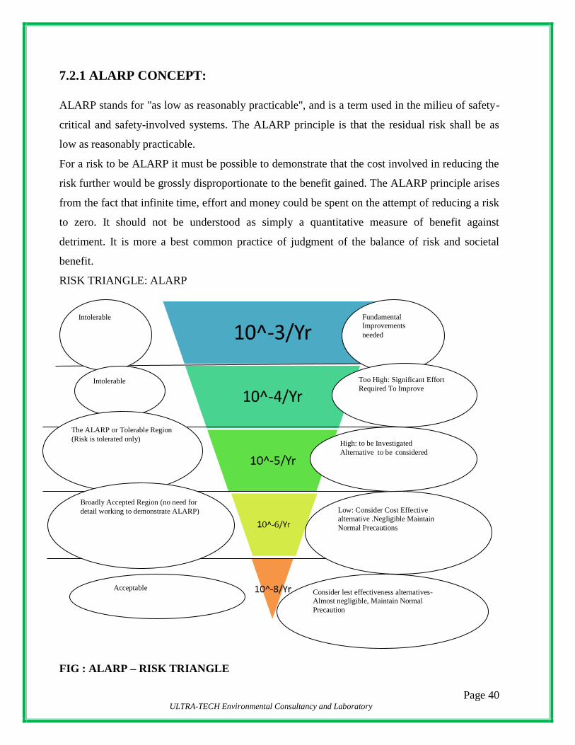
7.2.1 ALARP CONCEPT:
ALARP stands for "as low as reasonably practicable", and is a term used in the milieu of safety-
critical and safety-involved systems. The ALARP principle is that the residual risk shall be as
low as reasonably practicable.
For a risk to be ALARP it must be possible to demonstrate that the cost involved in reducing the
risk further would be grossly disproportionate to the benefit gained. The ALARP principle arises
from the fact that infinite time, effort and money could be spent on the attempt of reducing a risk
to zero. It should not be understood as simply a quantitative measure of benefit against
detriment. It is more a best common practice of judgment of the balance of risk and societal
benefit.
RISK TRIANGLE: ALARP
FIG : ALARP – RISK TRIANGLE
Fundamental
Improvements
needed
Too High: Significant Effort
Required To Improve
High: to be Investigated
Alternative to be considered
Low: Consider Cost Effective
alternative .Negligible Maintain Normal Precautions
Intolerable
Intolerable
The ALARP or Tolerable Region
(Risk is tolerated only)
Broadly Accepted Region (no need for
detail working to demonstrate ALARP)
Acceptable
BLE
Consider lest effectiveness alternatives-
Almost negligible, Maintain Normal
Precaution

Page 41 ULTRA-TECH Environmental Consultancy and Laboratory
If quantitative arguments are used the methods, assumptions and the criteria adopted for decision
making should be explained. For example in the case of fatality risks to people off-site it is
common practice [HSE, 1992] for the maximum tolerable level of individual fatality risk is set at
10-4 per year and for the broadly acceptable level to be set at 10-6 per year. The corresponding
figures for workers are 10-3 and 10-6 ALARP demonstration should be founded on the degree to
which good practice, engineering standards, recognized codes, guidance and standards, etc have
been adopted. The control measures introduced by this process will be usually satisfactory for
low hazard sites. In terms of the TOR framework this amount to using technology-based criteria
for making ALARP decisions, ie qualitative risk assessment. Such criteria will usually be
sufficient when inherently safe design principles have been adopted because then the scale of the
hazard should have been drastically reduced. As the level of proportionality increases, a decision
has to be made as to whether further risk reduction measures are reasonably practicable as
required as per OISD Standards.
7.2.2 EVENT TREE ANALYSIS & PROBABILITIES FOR THE RELEASE
OF DIFFERENT TYPES
Direct ignition Pool fire / Complete
Containment failure
Liquid
Delayed Ignition Explosion
Pool fire
No effect
Figure: 8.1 – Event tree for a release of flammable liquid
In quantitative risk analysis usually generic hypothesis concerning the loss of containment
initiating events are applied, in order to simplify the analysis. For example, for the loss of
containment from a storage tank: instantaneous release of the complete inventory, continuous
release of the complete inventory in 10 min and continuous release from a hole with a diameter

Page 42 ULTRA-TECH Environmental Consultancy and Laboratory
of 10 mm. Once these initiating events specified, it is necessary to develop the corresponding
event trees to establish which are the different sequences –depending on the properties of the
released material, the existing safety barriers, etc.– leading from each initiating event to the
diverse final outcomes or accident scenarios. In this communication a set of generic short event
trees are proposed for the main cases which can be found, as a function of the type of hazardous
material released. Values for the corresponding intermediate probabilities (immediate
ignition, delayed ignition, flame front acceleration, Pool fire, VCE etc.) are also proposed,
following both a literature survey and expert judgment.
A tank is susceptible to fire hazard, if a static charge or a spark ignites the vapour being released
from the rim vent, causing fire. If the fire is not controlled at the initial stage it can lead to
collapse of the roof and total liquid becomes exposed to fire. The hazard posed by such failure
and subsequent fire is intense thermal radiation. The thermal radiation emanating from such tank
fire can cause damage to nearby tanks and persons' in the vicinity. As per IP Code, thermally
protected facilities and storage tanks can withstand a thermal radiation of 32 KW/M2 while
unprotected tanks and process facilities can withstand only upto 8 KW/M2. Normal persons can
withstand an intensity of 1.5 KW/M2 for a long duration. A radiation intensity of 4.5 KW/M2 can
cause 1st degree burn if a man is exposed for more than 20 seconds.
Hazard distances due to thermal radiation as a result of fires in storage tanks and other areas have
been shown in the following pages.
7.2.3 FREQUENCY ANALYIS
The steps deals with determination how often – in terms of frequency per year – fire, explosion
& toxic hazards can occur. Specific event trees will be developed to calculate the frequencies of
scenarios. An event tree is a model that begins with a release case and ends up with various
incidents outcomes.
The likely hood of occurrence of the identified hazard scenarios is assessed by reviewing
historical accident data with previous studies. Event tree analysis is adopted to determine the
possible outcome from the identified hazardous events and to estimate the frequencies.

Page 43 ULTRA-TECH Environmental Consultancy and Laboratory
Estimates have been obtained from historical incident data on failure frequencies & from failure
sequence model (event trees). In this study the historical data available in international renowned
databases will be used.
Sl.No Failure Scenarios Likely Consequences Credible/
No Credible
Failure
Frequency
1 Tanks on Fire
i. Methanol Tank
ii. FO Tank
Thermal Radiation
Partially
credible
5 x 10⁻⁶
2 Vessel connection failure for inlet
/ outlet lines of Methanol &
FO(Road tanker loading)
Thermal Radiation for
MS,Methanol,Furnace
oil and also explosion
for MS
Partially
credible
5 x 10⁻⁶
3 TLF Pumps discharge lines Full
bore failure for Methanol & FO
(Road Tanker Loading)
do
Non
Credible
3 x 10⁻⁶
4 Gasket failure in pump discharge
line Methanol & FO (Road
Tanker Loading Pump)
Thermal radiation Credible 0.5 x 10⁻⁶
P/H of
operation.
5 Failure of 3’ dia loading arm
Methanol & FO
-do- Partially
Credible
3 x 10⁻⁸
P/H of
operation
6 Failure of 3’ dia unloading hose
Methanol & FO
-do- Credible 3 x 10-
5P/H of
operation

Page 44 ULTRA-TECH Environmental Consultancy and Laboratory
7.3 CONSIDERATION FOR MAXIMUM CREDIBLE ACCIDENT SCENARIO:
HAZARD ASSESSMENT (QUANTIFICATION)
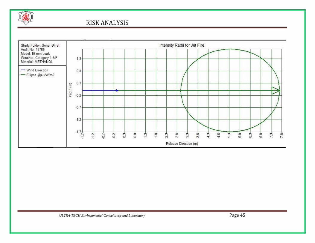
7.3.1 JET FIRE
Scenario – 1: Jet fire on Methanol
Specification considered
1. Product Methanol
2. Tank No T-202
3. Leakage through hole - dia 10 mm
4. Pump discharge 80 KL/H
5. Duration 600 Second
METEROLOGICAL DATA CONSIDERED
Temperature(Max ) 36o C / 309 K
Humidity(Min) 41%
Maximum temperature of 36o C / 309 K and minimum humidity of 41 % have been considered
for the calculation of damage distance in the case of Jet fire radiation heat intensity in
KW/M2
Result
Sl
no
Scenario
Stability
Condition
Distance in (m)
37.5 kW/m2 12.5 kW/m2 4,kW/m2
1. Methanol
1.5F NR NR 7.72
5D NR NR 5.61
RISK ANALYSIS
ULTRA-TECH Environmental Consultancy and Laboratory Page 45

Page 46 ULTRA-TECH Environmental Consultancy and Laboratory

RISK ANALYSIS
ULTRA-TECH Environmental Consultancy and Laboratory Page 47
Scenario – 2: Jet fire on Methanol
Specification considered
1. Product Methanol
2. Tank No T-202
3. Leakage through hole - dia CR
4. Pump discharge 80 KL/H
5. Duration 600 Second
METEROLOGICAL DATA CONSIDERED
Temperature(Max ) 36o C / 309 K
Humidity(Min) 41%
Maximum temperature of 36o C / 309 K and minimum humidity of 41 % have been considered
for the calculation of damage distance in the case of Jet fire radiation heat intensity in
KW/M2
Result
Sl
no
Scenario
Stability
Condition
Distance in (m)
37.5 kW/m2 12.5 kW/m2 4,kW/m2
1. Methanol
1.5F NR NR NR
5D NR NR NR

Page 48 ULTRA-TECH Environmental Consultancy and Laboratory
Scenario – 3 : Jet fire on Class A (Propose product)
Specification considered
1. Product Proposed class A product
2. Tank No T-205
3. Leakage through hole - dia 10 mm
4. Pump discharge 80 KL/H
5. Duration 600 Second
METEROLOGICAL DATA CONSIDERED
Temperature(Max ) 36o C / 309 K
Humidity(Min) 41%
Maximum temperature of 36o C / 309 K and minimum humidity of 41 % have been considered
for the calculation of damage distance in the case of Jet fire radiation heat intensity in
KW/M2
Result
Sl
no
Scenario
Stability
Condition
Distance in (m)
37.5 kW/m2 12.5 kW/m2 4,kW/m2
1. Proposed
class A
product
1.5F NR NR 7.92
5D NR NR 5.68

RISK ANALYSIS
ULTRA-TECH Environmental Consultancy and Laboratory Page 49

Page 50 ULTRA-TECH Environmental Consultancy and Laboratory
RISK ANALYSIS
ULTRA-TECH Environmental Consultancy and Laboratory Page 51
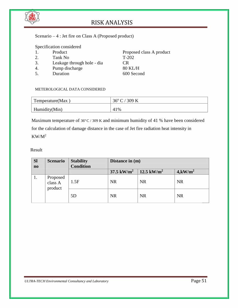
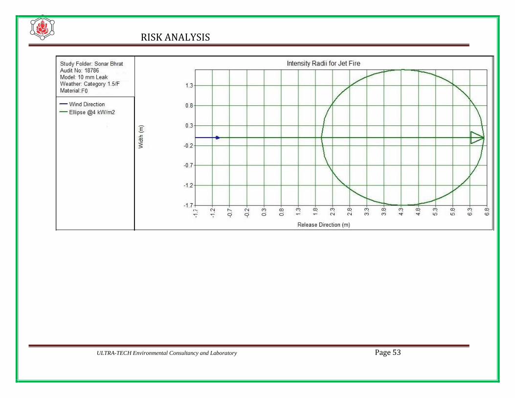
Scenario – 4 : Jet fire on Class A (Proposed product)
Specification considered
1. Product Proposed class A product
2. Tank No T-202
3. Leakage through hole - dia CR
4. Pump discharge 80 KL/H
5. Duration 600 Second
METEROLOGICAL DATA CONSIDERED
Temperature(Max ) 36o C / 309 K
Humidity(Min) 41%
Maximum temperature of 36o C / 309 K and minimum humidity of 41 % have been considered
for the calculation of damage distance in the case of Jet fire radiation heat intensity in
KW/M2
Result
Sl
no
Scenario
Stability
Condition
Distance in (m)
37.5 kW/m2 12.5 kW/m2 4,kW/m2
1. Proposed
class A
product
1.5F NR NR NR
5D NR NR NR

Page 52 ULTRA-TECH Environmental Consultancy and Laboratory
Scenario – 5: Jet fire on FO
Specification considered
1. Product FO
2. Tank No T-104
3. Leakage through hole - dia 10 mm
4. Pump discharge 60 KL/H
5. Duration 600 Second
METEROLOGICAL DATA CONSIDERED
Temperature(Max ) 36o C / 309 K
Humidity(Min) 41%
Maximum temperature of 36o C / 309 K and minimum humidity of 41 % have been considered
for the calculation of damage distance in the case of Jet fire radiation heat intensity in
KW/M2
Result
Sl
no
Scenario
Stability
Condition
Distance in (m)
37.5 kW/m2 12.5 kW/m2 4,kW/m2
1. FO
1.5F NR NR 3.50
5D NR NR 1.51
RISK ANALYSIS
ULTRA-TECH Environmental Consultancy and Laboratory Page 53

Page 54 ULTRA-TECH Environmental Consultancy and Laboratory

RISK ANALYSIS
ULTRA-TECH Environmental Consultancy and Laboratory Page 55
Scenario – 6 : Jet fire on FO
Specification considered
1. Product FO
2. Tank No T-104
3. Leakage through hole - dia CR
4. Pump discharge 80 KL/H
5. Duration 600 Second
METEROLOGICAL DATA CONSIDERED
Temperature(Max ) 36o C / 309 K
Humidity(Min) 41%
Maximum temperature of 36o C / 309 K and minimum humidity of 41 % have been considered
for the calculation of damage distance in the case of Jet fire radiation heat intensity in
KW/M2
Result
Sl
no
Scenario
Stability
Condition
Distance in (m)
37.5 kW/m2 12.5 kW/m2 4,kW/m2
1. FO
1.5F NR NR NR
5D NR NR NR

Page 56 ULTRA-TECH Environmental Consultancy and Laboratory
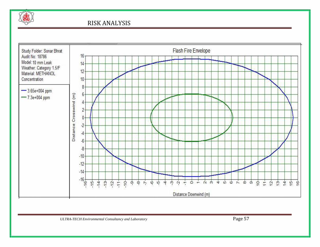
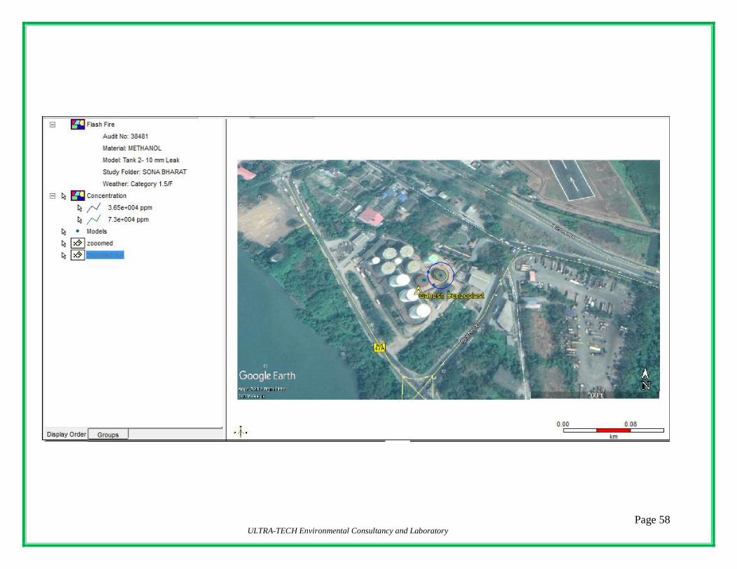
Scenario – 7: Flash Fire on Methanol
Specification considered
1. Product Methanol
2. Tank No T-201
3. Leakage through hole - dia 10 mm
4. Pump discharge 80 KL/H
5. Duration 600 Second
METEROLOGICAL DATA CONSIDERED
Temperature(Max ) 36o C / 309 K
Humidity(Min) 41%
Maximum temperature of 36o C / 309 K and minimum humidity of 41 % have been considered
for the calculation of damage distance in the case of Jet fire radiation heat intensity in
KW/M2
Result
Sl
no
Scenario
Stability
Condition
Distance in (m)
1. Methanol
1.5F 6.21
5D 2.96
RISK ANALYSIS
ULTRA-TECH Environmental Consultancy and Laboratory Page 57
Page 58 ULTRA-TECH Environmental Consultancy and Laboratory

RISK ANALYSIS
ULTRA-TECH Environmental Consultancy and Laboratory Page 59
Scenario – 8: Flash Fire on Methanol
Specification considered
1. Product Methanol
2. Tank No T-201
3. Leakage through hole - dia CR
4. Pump discharge 80 KL/H
5. Duration 600 Second
METEROLOGICAL DATA CONSIDERED
Temperature(Max ) 35o C / 308 K
Humidity(Min) 68%
Maximum temperature of 36o C / 309 K and minimum humidity of 41 % have been considered
for the calculation of damage distance in the case of Jet fire radiation heat intensity in
KW/M2
Result
Sl
no
Scenario
Stability
Condition
Distance in (m)
1. MS
1.5F 605.68
5D 262.50
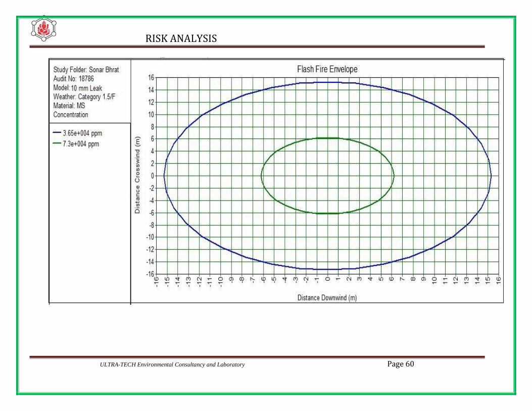
RISK ANALYSIS
ULTRA-TECH Environmental Consultancy and Laboratory Page 60

Page 61 ULTRA-TECH Environmental Consultancy and Laboratory

RISK ANALYSIS
ULTRA-TECH Environmental Consultancy and Laboratory Page 62
Scenario – 9: Flash Fire on Class A Product Tank
Specification considered
1. Product Class A
2. Tank No T-205
3. Leakage through hole - dia 10 mm
4. Pump discharge 80 KL/H
5. Duration 600 Second
METEROLOGICAL DATA CONSIDERED
Temperature(Max ) 36o C / 309 K
Humidity(Min) 41%
Maximum temperature of 36o C / 309 K and minimum humidity of 41 % have been considered
for the calculation of damage distance in the case of Jet fire radiation heat intensity in
KW/M2
Result
Sl
no
Scenario
Stability
Condition
Distance in (m)
1. Methanol
1.5F 7.21
5D 3.01

RISK ANALYSIS
ULTRA-TECH Environmental Consultancy and Laboratory Page 63

RISK ANALYSIS
ULTRA-TECH Environmental Consultancy and Laboratory Page 64
Scenario – 10: Flash Fire on Class A Product
Specification considered
1. Product Class A
2. Tank No T-205
3. Leakage through hole - dia CR
4. Pump discharge 80 KL/H
5. Duration 600 Second
METEROLOGICAL DATA CONSIDERED
Temperature(Max ) 35o C / 308 K
Humidity(Min) 68%
Maximum temperature of 36o C / 309 K and minimum humidity of 41 % have been considered
for the calculation of damage distance in the case of Jet fire radiation heat intensity in
KW/M2
Result
Sl
no
Scenario
Stability
Condition
Distance in (m)
1. MS
1.5F 805.68
5D 362.50
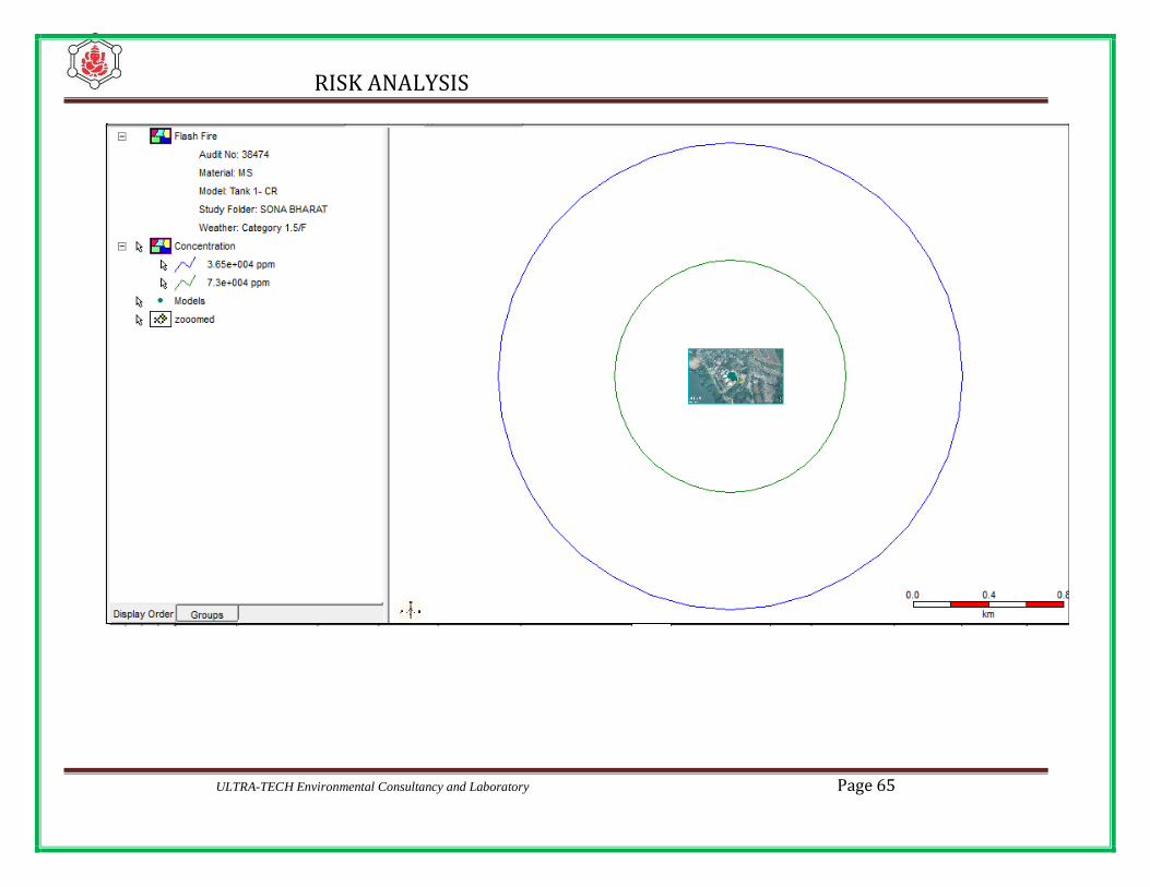
RISK ANALYSIS
ULTRA-TECH Environmental Consultancy and Laboratory Page 65
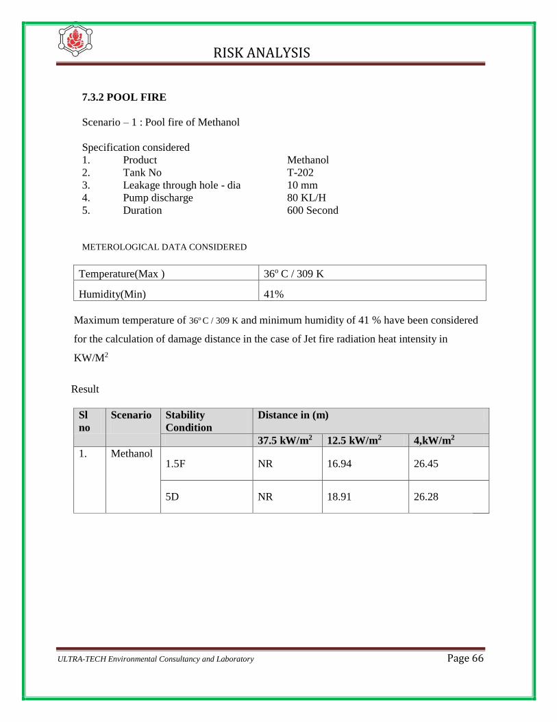
RISK ANALYSIS
ULTRA-TECH Environmental Consultancy and Laboratory Page 66
7.3.2 POOL FIRE
Scenario – 1 : Pool fire of Methanol
Specification considered
1. Product Methanol
2. Tank No T-202
3. Leakage through hole - dia 10 mm
4. Pump discharge 80 KL/H
5. Duration 600 Second
METEROLOGICAL DATA CONSIDERED
Temperature(Max ) 36o C / 309 K
Humidity(Min) 41%
Maximum temperature of 36o C / 309 K and minimum humidity of 41 % have been considered
for the calculation of damage distance in the case of Jet fire radiation heat intensity in
KW/M2
Result
Sl
no
Scenario
Stability
Condition
Distance in (m)
37.5 kW/m2 12.5 kW/m2 4,kW/m2
1. Methanol
1.5F NR 16.94 26.45
5D NR 18.91 26.28

RISK ANALYSIS
ULTRA-TECH Environmental Consultancy and Laboratory Page 67

Page 68 ULTRA-TECH Environmental Consultancy and Laboratory

RISK ANALYSIS
ULTRA-TECH Environmental Consultancy and Laboratory Page 69
Scenario – 2: Pool fire on Methanol
Specification considered
1. Product Methanol
2. Tank No T-205
3. Leakage through hole - dia CR
4. Pump discharge 80 KL/H
5. Duration 600 Second
METEROLOGICAL DATA CONSIDERED
Temperature(Max ) 36o C / 309 K
Humidity(Min) 41%
Maximum temperature of 36o C / 309 K and minimum humidity of 41 % have been considered
for the calculation of damage distance in the case of Jet fire radiation heat intensity in
KW/M2
Result
Sl
no
Scenario
Stability
Condition
Distance in (m)
37.5 kW/m2 12.5 kW/m2 4,kW/m2
1. Methanol
1.5F 512.67 717.59 1009.38
5D 523.55 745.87 1013.65
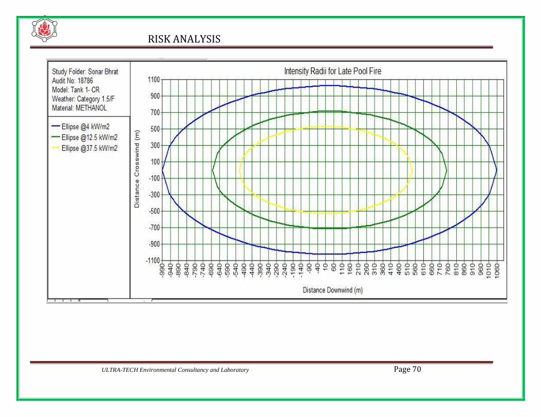
RISK ANALYSIS
ULTRA-TECH Environmental Consultancy and Laboratory Page 70

Page 71 ULTRA-TECH Environmental Consultancy and Laboratory

RISK ANALYSIS
ULTRA-TECH Environmental Consultancy and Laboratory Page 72
Scenario – 3 : Pool fire on Class A Proposed Product
Specification considered
1. Product Proposed Class A Product
2. Tank No T-205
3. Leakage through hole - dia 10 mm
4. Pump discharge 80 KL/H
5. Duration 600 Second
METEROLOGICAL DATA CONSIDERED
Temperature(Max ) 36o C / 309 K
Humidity(Min) 41%
Maximum temperature of 36o C / 309 K and minimum humidity of 41 % have been considered
for the calculation of damage distance in the case of Jet fire radiation heat intensity in
KW/M2
Result
Sl
no
Scenario
Stability
Condition
Distance in (m)
37.5 kW/m2 12.5 kW/m2 4,kW/m2
1. Proposed
Class A
Product
1.5F NR 16.94 26.45
5D NR 18.91 26.28
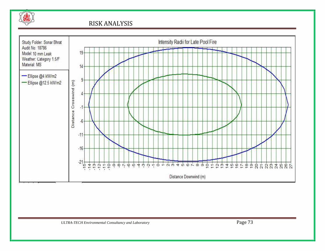
RISK ANALYSIS
ULTRA-TECH Environmental Consultancy and Laboratory Page 73

Page 74 ULTRA-TECH Environmental Consultancy and Laboratory

RISK ANALYSIS
ULTRA-TECH Environmental Consultancy and Laboratory Page 75
Scenario – 4 : Pool fire of Proposed Class A Product
Specification considered
1. Product Proposed Class A Product
2. Tank No T-202
3. Leakage through hole - dia CR
4. Pump discharge 80 KL/H
5. Duration 600 Second
METEROLOGICAL DATA CONSIDERED
Temperature(Max ) 36o C / 309 K
Humidity(Min) 41%
Maximum temperature of 36o C / 309 K and minimum humidity of 41 % have been considered
for the calculation of damage distance in the case of Jet fire radiation heat intensity in
KW/M2
Result
Sl
no
Scenario
Stability
Condition
Distance in (m)
37.5 kW/m2 12.5 kW/m2 4,kW/m2
1. Proposed
Class A
Product
1.5F 539.44 752.48 1056.25
5D 551.42 781.27 1060.22

RISK ANALYSIS
ULTRA-TECH Environmental Consultancy and Laboratory Page 76

Page 77 ULTRA-TECH Environmental Consultancy and Laboratory

RISK ANALYSIS
ULTRA-TECH Environmental Consultancy and Laboratory Page 78
Scenario – 5 : Pool Fire on FO
Specification considered
1. Product FO
2. Tank No T-104
3. Leakage through hole - dia 10 mm
4. Pump discharge 60 KL/H
5. Duration 600 Second
METEROLOGICAL DATA CONSIDERED
Temperature(Max ) 36o C / 309 K
Humidity(Min) 41%
Maximum temperature of 36o C / 309 K and minimum humidity of 41 % have been considered
for the calculation of damage distance in the case of Jet fire radiation heat intensity in
KW/M2
Result
Sl
no
Scenario
Stability
Condition
Distance in (m)
37.5 kW/m2 12.5 kW/m2 4,kW/m2
1. FO
1.5F NR 9.94 15.45
5D NR 10.01 15.21
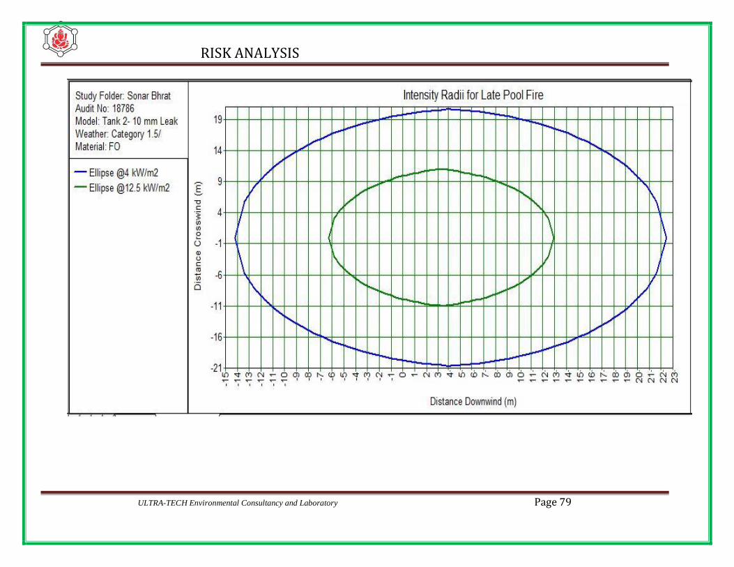
RISK ANALYSIS
ULTRA-TECH Environmental Consultancy and Laboratory Page 79

Page 80 ULTRA-TECH Environmental Consultancy and Laboratory
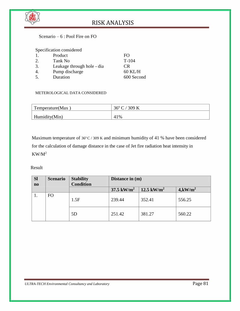
RISK ANALYSIS
ULTRA-TECH Environmental Consultancy and Laboratory Page 81
Scenario – 6 : Pool Fire on FO
Specification considered
1. Product FO
2. Tank No T-104
3. Leakage through hole - dia CR
4. Pump discharge 60 KL/H
5. Duration 600 Second
METEROLOGICAL DATA CONSIDERED
Temperature(Max ) 36o C / 309 K
Humidity(Min) 41%
Maximum temperature of 36o C / 309 K and minimum humidity of 41 % have been considered
for the calculation of damage distance in the case of Jet fire radiation heat intensity in
KW/M2
Result
Sl
no
Scenario
Stability
Condition
Distance in (m)
37.5 kW/m2 12.5 kW/m2 4,kW/m2
1. FO
1.5F 239.44 352.41 556.25
5D 251.42 381.27 560.22

RISK ANALYSIS
ULTRA-TECH Environmental Consultancy and Laboratory Page 82
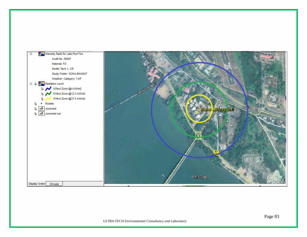
Page 83 ULTRA-TECH Environmental Consultancy and Laboratory

RISK ANALYSIS
ULTRA-TECH Environmental Consultancy and Laboratory Page 84
7.3.2 OVERPRESSURE
Scenario – 1: Overpressure of Methanol
Specification considered
1. Product Methanol
2. Tank No T-202
3. Leakage through hole - dia 10 mm
4. Pump discharge 80 KL/H
5. Duration 600 Second
METEROLOGICAL DATA CONSIDERED
Temperature(Max ) 36o C / 309 K
Humidity(Min) 41%
Maximum temperature of 36o C / 309 K and minimum humidity of 41 % have been considered
for the calculation of damage distance in the case of Jet fire radiation heat intensity in
KW/M2
Result
Sl
no
Scenario
Stability
Condition
Distance in (m)
0.2 0.1 0.02
1. Methanol
1.5F 11.06 11.37 15.27
5D NR NR NR

RISK ANALYSIS
ULTRA-TECH Environmental Consultancy and Laboratory Page 85

Page 86 ULTRA-TECH Environmental Consultancy and Laboratory

RISK ANALYSIS
ULTRA-TECH Environmental Consultancy and Laboratory Page 87
Scenario – 2: Overpressure of Methanol
Specification considered
1. Product Methanol
2. Tank No T-202
3. Leakage through hole - dia CR
4. Pump discharge 80 KL/H
5. Duration 600 Second
METEROLOGICAL DATA CONSIDERED
Temperature(Max ) 36o C / 309 K
Humidity(Min) 41%
Maximum temperature of 36o C / 309 K and minimum humidity of 41 % have been considered
for the calculation of damage distance in the case of Jet fire radiation heat intensity in
KW/M2
Result
Sl
no
Scenario
Stability
Condition
Distance in (m)
0.2 bar 0.1 bar 0.02 bar
1. Methanol
1.5F 701.02 707.17 855.26
5D 331.69 335.11 575.67
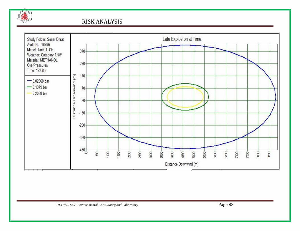
RISK ANALYSIS
ULTRA-TECH Environmental Consultancy and Laboratory Page 88
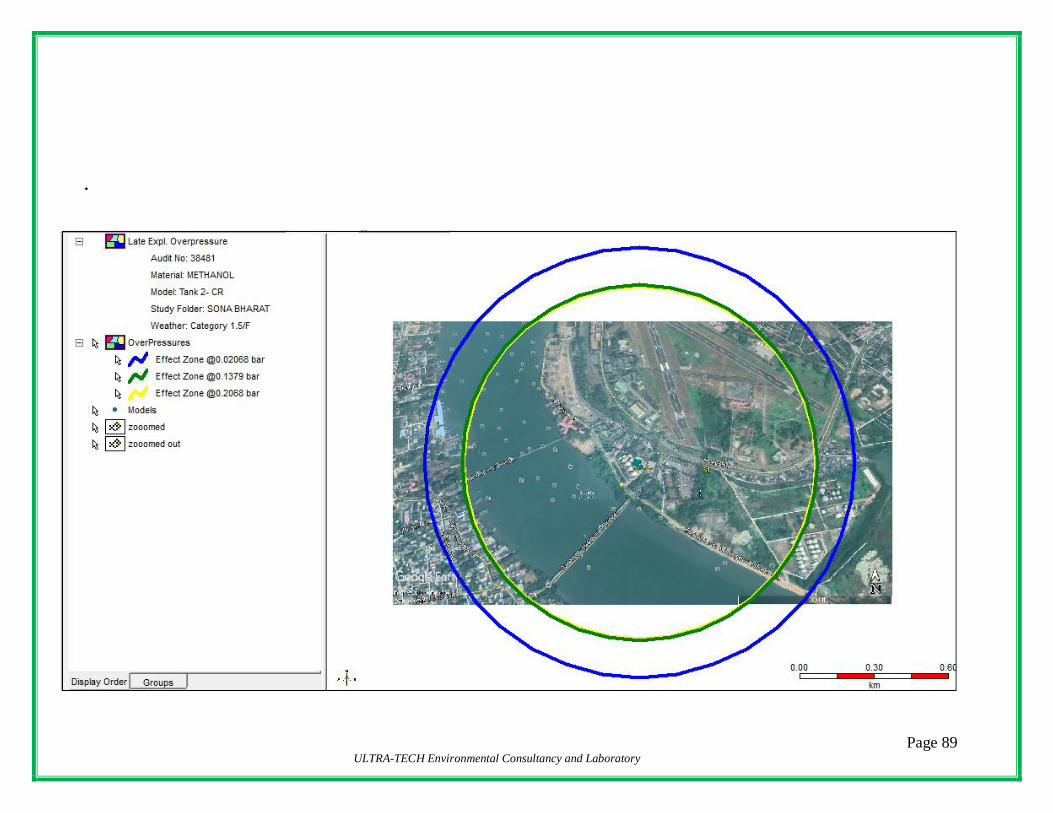
Page 89 ULTRA-TECH Environmental Consultancy and Laboratory
.
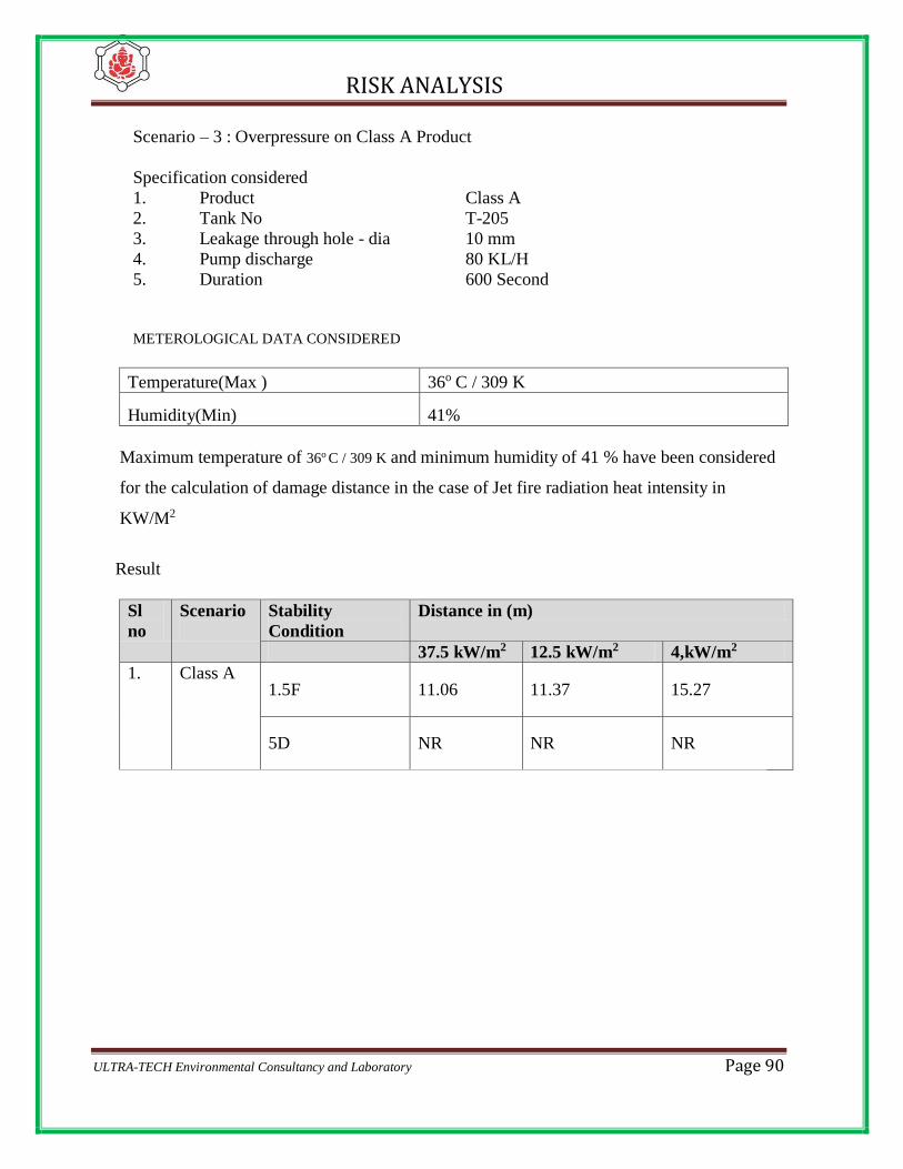
RISK ANALYSIS
ULTRA-TECH Environmental Consultancy and Laboratory Page 90
Scenario – 3 : Overpressure on Class A Product
Specification considered
1. Product Class A
2. Tank No T-205
3. Leakage through hole - dia 10 mm
4. Pump discharge 80 KL/H
5. Duration 600 Second
METEROLOGICAL DATA CONSIDERED
Temperature(Max ) 36o C / 309 K
Humidity(Min) 41%
Maximum temperature of 36o C / 309 K and minimum humidity of 41 % have been considered
for the calculation of damage distance in the case of Jet fire radiation heat intensity in
KW/M2
Result
Sl
no
Scenario
Stability
Condition
Distance in (m)
37.5 kW/m2 12.5 kW/m2 4,kW/m2
1. Class A
1.5F 11.06 11.37 15.27
5D NR NR NR
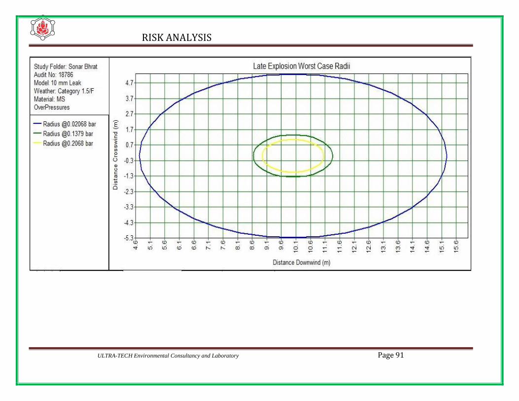
RISK ANALYSIS
ULTRA-TECH Environmental Consultancy and Laboratory Page 91
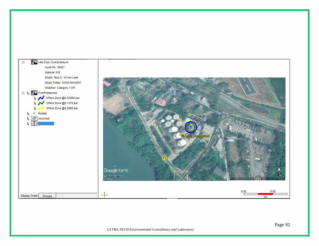
Page 92 ULTRA-TECH Environmental Consultancy and Laboratory
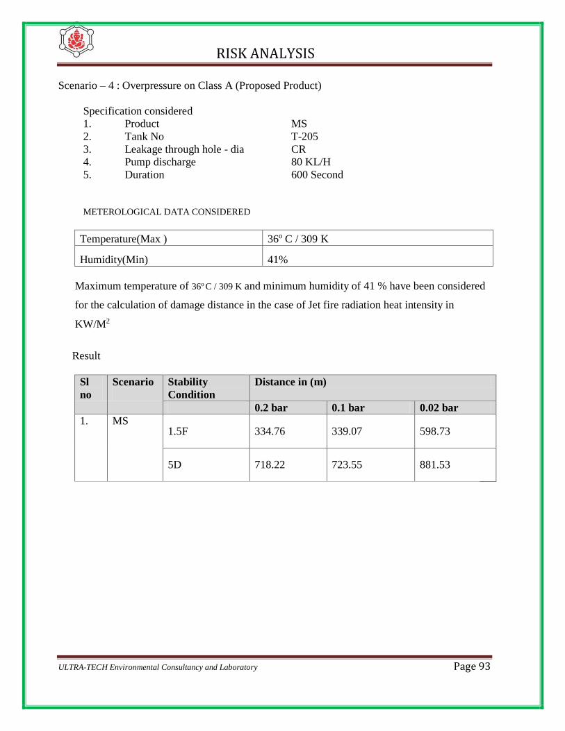
RISK ANALYSIS
ULTRA-TECH Environmental Consultancy and Laboratory Page 93
Scenario – 4 : Overpressure on Class A (Proposed Product)
Specification considered
1. Product MS
2. Tank No T-205
3. Leakage through hole - dia CR
4. Pump discharge 80 KL/H
5. Duration 600 Second
METEROLOGICAL DATA CONSIDERED
Temperature(Max ) 36o C / 309 K
Humidity(Min) 41%
Maximum temperature of 36o C / 309 K and minimum humidity of 41 % have been considered
for the calculation of damage distance in the case of Jet fire radiation heat intensity in
KW/M2
Result
Sl
no
Scenario
Stability
Condition
Distance in (m)
0.2 bar 0.1 bar 0.02 bar
1. MS
1.5F 334.76 339.07 598.73
5D 718.22 723.55 881.53
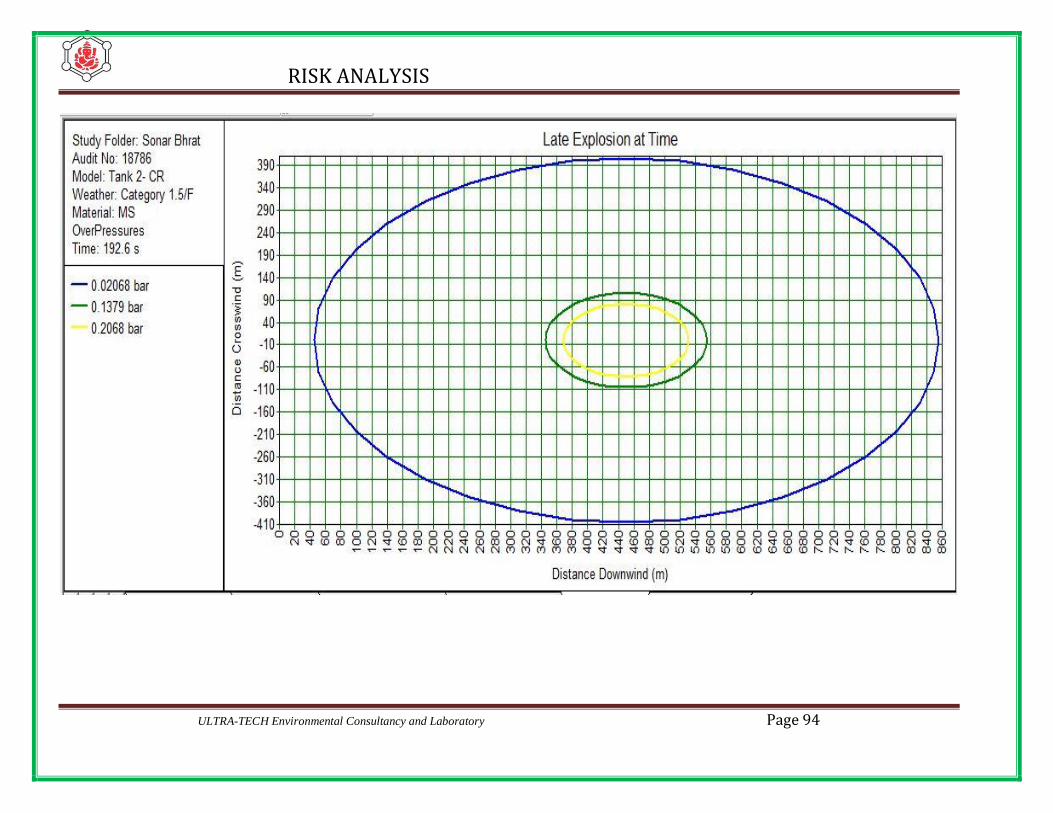
RISK ANALYSIS
ULTRA-TECH Environmental Consultancy and Laboratory Page 94
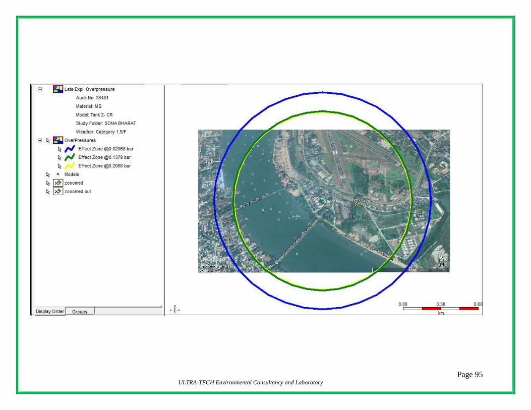
Page 95 ULTRA-TECH Environmental Consultancy and Laboratory

RISK ANALYSIS
ULTRA-TECH Environmental Consultancy and Laboratory Page 96
7.4 MODELING SOFTWARE
A site specific consequence analysis of the accidental release scenarios was conducted using the
commercially available Process Hazards Analysis Software Tool (PHAST) consequence
modeling software, version 6.7. M/S DNV’s Software is responsible for the development of a
number of established, world leading, hazard and risk modeling software tools. These
commercially available software tools include the consequence modeling package PHAST, the
risk analysis tools SAFETI /PHAST RISK.
7.5 ACTION DURING FIRE
7.5.1 Storage Tank in Fire
a) A fire burning at the vent will not normally flash back into tank and
explode, if the tank contains product since flame arresters are provided
b) Start cooling of tanks by using water sprinklers provided on tanks as well as by
wet jets.
c) Close all valves since any removal of product will result in air being sucked
inside, with the resultant flash back and explosion.
d) Close manhole covers of other tanks if they are open. Also stop loading /
Receipt of tank wagons, into / out of the tank since it will result in eviction
of vapour due to displacement and subsequent intensification of fire.
e) Use foam to extinguish fire. Small fire can be handled with portable fire
extinguishers.
f) Fire in tank will normally burn quietly till the oxygen is consumed unless
temperature of the product is allowed to increase uncontrolled. Hence, care must
Page 97 ULTRA-TECH Environmental Consultancy and Laboratory
be taken to ensure that product temperature does not go high by cooling with
water sprinklers & jets. This also avoids possibility of tank rupture due to
hydrostatic pressure
g) When sufficient air vapour mixture is available inside the tank as in the case
during removal of products from tank on fire there is a distant possibility of tank
roof collapse or blow out. In such cases, immediate action should be taken to
ensure that the fire does not spread to other areas. If there is product spill to
outside, foam should be used to cover the same.
H) In such cases, foam should be pumped to inside the tank for blanketing the fire
and simultaneously taking action to cool the tank shell with water and also
removing the product by pumping it cut to some other tank.
i) Uncontrolled use of water on the burning product will result in product spill over
and spread of fire. In the case of heavy ends this will result in boil over and
frothing at the surface.
j) When heavy ends like MS or FO burn, a layer of hot oil is formed below the
surface, which extends towards the bottom. Temperature of this layer is of the
order of 250° C to 300° C much above the boiling point of water. When water
turns into steam, it expands appx. 1600 times and this result in boil over. The boil
over may overflow the tank resulting in spreading of fire. Hence, in such fire, cool
down the tank by continuous water jet on the tank shell, transfer the product to
other tanks and judiciously use foam to smoothen fire.
7.5.2 Pool Fire at TLF Gantry.
A) Discharge DCP to prevent fire from spreading.
B) Shut down the pumps by cutting of power supply.
C) Remove any person who is working in the effected area.

Page 98 ULTRA-TECH Environmental Consultancy and Laboratory
D) Close the valves of either side to starve the fire close all tank wagon valves and
manifold valves.
E) Put foam on burning oil spills
F) Put foam on oil spills. Do not splash burning oil.
G) Use DCP or CO2 fire extinguisher on electrical fire.
H) Wet down the structure close to the fire with water
7.5.3 Gasket Failure
a. Stop Pumping
b. Close the valves of either side of flange
c. Dig pits to collect oil.
d. Built earth dykes around the oil pool to prevent spreading of burning oil.
e. Take care of the oil dropping from the leak even after extinguishing fire as
fire may occur again due to heating of oil dropped. Try to collect the oil in
containers.
f. Take action for replacement of gasket/ repair leak with due care.
7.5.4 General
a) Incase of Oil spill the same should be blanketed with foam in order to avoid
contact with source of ignition.
b) Use DCP or CO2 fire extinguisher on Electrical fire.
c) Wet down structure close to the fire with water.
d) Discharge DCP to prevent fire from spreading.
e) In case flammable liquid pool due to containment failure, pipeline rupture within
the dyke area it is suggested to cover the flame with foam blanket.
Page 99 ULTRA-TECH Environmental Consultancy and Laboratory
CHAPTER-8 : RISKS AND FAILURE PROBABILITY
The term Risk involves the quantitative evaluation of likelihood of any undesirable event
as well as likelihood of harm of damage being caused to life,property and environment.
This harm or damage may only occur due to sudden/accidental release of any hazardous
material from the containment. This sudden/accidental release of hazardous material can
occur due to failure of component systems. It is difficult to ascertain the failure
probability of any system because it will depend on the components of the system. Even
if failure occurs, the probability of fire and the extent of damage will depend on many
factors like,
A) Quantity and physical properties of material released.
B) Source of ignition
C) Wind velocity and direction
D) Presence of population, properties etc nearly.
Failure frequency of different components like pipes, valves, instruments, pressure
vessels and other equipment manufactured in India are not available. The statutory
authority has tried to collect the information and form an acceptable data bank to be used
under Indian condition.
Failure frequency data for some components accepted in U.S.A and European
Countries are given Table -14

Page 100 ULTRA-TECH Environmental Consultancy and Laboratory
TABLE -14
FAILURE FREQUENCY DATA
Sl.No Item Failure Frequency /
106 years
1 Shell Failure
a) Process/pressure vessel
b) Pressurized Storage Vessel
3
1
2 Full Bore Vessel Connection Failure
(Diameter MM)
<25
40
50
80
100
>150
30
10
7.5
5
4
3
3 Full Bore Process Pipeline Failure
D< 50mm
50<d<150mm
D>150mm
0.3*
0.09*
0.03*
4 Articulated Loading / Unloading arm
Failure
30 x 108 **
* Failure frequency expressed in (n/106 years)
** Failure frequency expressed in (hr of operation)
Page 101 ULTRA-TECH Environmental Consultancy and Laboratory
CHAPTER-9 : RECOMMENDATIONS & CONCLUSIONS
The recommendations & conclusions as revealed from Risk Analysis study are as
follows:
i) The individual Risk value of 1.0 E-6/ year as evident from the ISO Risk
contour is not always confined within the plant premises. Hazard distances
arrived from the consequence analysis also reveals that in most of the
cases hazard is not always confined within the terminal premises.
ii) Health check and maintenance of the equipment including storage tanks
and pipelines should be done at regular intervals to avoid any major
failure. History sheet of all major equipment giving the details of
fabrication data / design data to be maintained.
iii) Instruments and trip interlocks should be checked and calibrated at regular
intervals to prevent any wrong signaling and consequent failures.
iv) Fire fighting system as well as portable fire-fighting appliances should
be always kept in good working condition. Safety appliances should be
also checked and kept in good working condition.
v) Mock Drills should be conducted at regular intervals.
vi) To reduce the failure frequency due care has been taken in design,
construction, inspection and operation. Well-established codes of practices
have been followed for design, inspection and construction of the facility.
vii) The Terminal should be operated by experienced personnel trained for
operation of such facility and also in fire fighting. Safe operating practice (
SOP) to be drawn and critical SOP to be displayed near the TLF,
Tankfarm, Pump house and manifold.

Page 102 ULTRA-TECH Environmental Consultancy and Laboratory
viii) Smoking should be strictly prohibited inside the Terminal.
ix) Non -sparking tools should be used for maintenance to avoid any spark.
x) The storage tanks, pipelines and facilities in Tank Lorry Filling Shed
should be properly earthed to avoid accumulation of static electricity.
Bounding to be ensured for TLF operation. Tripping arrangement
recommended in case of failure in earthing / bounding system.
xi) Entry of personnel should be restricted inside the licensed area.
xii) A elaborate Disaster Control Management Plan containing a mutual
aid agreement should be drawn to meet major exigencies.
xiii) 2 No. Trolley Mounted Foam Monitors should be maintained in order
xiv) Failure data must be recorded.
xv) Maintenance schedule is to be drawn and the same should be strictly
adhered to.