Embed Size (px)
Citation preview

Quantitative Risk Analysis of High
Safety-significant Safety-related
DI&C Systems using IRADIC
Technology
Han Bao, Hongbin Zhang
10/14/2021
RISA/NRC Coordination Meeting

• Some technical challenges remain in software common cause failure (CCF) analysis
in the high safety-significant safety-related (HSSSR) DI&C systems:
• Are current methods able to capture potential CCFs in DI&C systems?
• Various methods: FMEA, FTA, STPA, HAZCADS, HAZOP…
• Software should not be analyzed in isolation from the complete digital system.
• Not easy to identify new failure modes in single software and interactions between different components in a DI&C
system (“Type II interaction”).
• Is qualitative evaluation sufficient for addressing software CCFs in HSSSR DI&C systems?
• Most of the STPA-based approaches focus on the identification of software failures but not the quantification of their
probabilities.
• Instead, a conservative bounding assessment is performed to evaluate their impacts to plant safety (e.g., ∆ Core
Damage Frequency, [CDF]), which may lead to an underestimation of safety margins gained by plant digitalization.
• How to quantitatively evaluate CCF-related impacts to DI&C systems and plant response?
• This proposes a need to develop an integrated strategy to include both qualitative hazard analysis and quantitative
reliability and consequence analysis for addressing software CCF issues in the HSSSR DI&C systems of nuclear
power plants (NPPs).
Challenges in Addressing CCF in HSSSR DI&C Systems
2
Schematic of Integrated Risk Assessment
Technology for Digital I&C Systems (IRADIC)
3
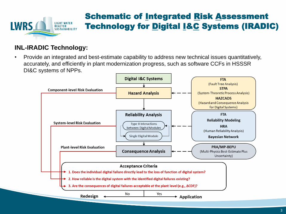
INL-IRADIC Technology:
• Provide an integrated and best-estimate capability to address new technical issues quantitatively,
accurately, and efficiently in plant modernization progress, such as software CCFs in HSSSR
DI&C systems of NPPs.

How IRADIC Could Support Industry for Risk
Informing HSSSR DI&C Designs or Upgrades?
4
• We expect IRADIC to become an integrated risk-informed tool for vendors and utilities to meet
regulatory requirements and optimize the diversity and defense-in-depth (D3) applications in the
DI&C designs and upgrades.
• Quantitative vs. Qualitative
• Software Failure Probability DI&C System Failure Probability ∆CDF
• Balance of risk and cost in design stage
• Management strategy of CCFs
• All elimination vs. selective elimination
• Level of redundancy
• 4 divisions vs. 2 divisions
• 4 vs. 2 local coincidence logic processors per division
• Level of diversity
• Design: Analog? Digital? Both?
• Software: Design requirements, programming language…
• Equipment: Manufacturers, designs, architectures…
4-division digital Reactor Trip System

(I). Redundancy-guided System-theoretic Hazard Analysis
Hazard analysis in IRADIC:
• Incorporates the concept of combining FTA and STPA from HAZCADS.
• Reframes STPA in a redundancy-guided way to address CCF concerns
in highly redundant HSSSR DI&C systems.
• Identifies failures in Type II interactions (between different components
of a DI&C system).
5
Workflow of the Redundant-guided System-theoretic Hazard Analysis
(RESHA) in IRADIC

Determine Unsafe Control Actions (UCAs) Based on a Redundancy-guided Application of STPA
Redundancy of• Reactor trip breakers
• LCL processors
• Division level
• Unit level (two racks per division)
• Module level (two processors per rack)
• Bistable processors
• Division level
• Unit level (two processors per division)
6
Illustration of a multilayer control structure that captures UCAs in different levels of redundancy

Key CCFs Leading to Potential Single Points of Failure (SPOFs) in the Design
Causal factors of UCAs (e.g., software failures)
• Category 1: Inner software failure
• Software design defect
• Software implementation failure
• Category 2: Incorrect feedback or inputs
• Failures in Type II interactions
Table 5: First order cut sets for the RPS system.
Number Cut set Description
1 SP-HD-CCF Selective processor hardware CCF.
2 LC-DOM-HD-CCF Logic cabinet digital output module hardware CCF.
3 RTB-UV-HD-CCF Reactor trip breaker undervoltage hardware CCF.
4 LC-BP-HD-CCF Logic bistable processor hardware CCF.
5 LC-LP-HD-CCF Logic cabinet logic processor hardware CCF
6 LC-LP-SF-CCF-TA Logic cabinet logic processor software CCF type A.
7 LC-LP-SF-CCF-TC Logic cabinet logic processor software CCF type C.
8 LC-DOM-SF-CCF-TA Logic cabinet digital output module software CCF type A.
9 LC-DOM-SF-CCF-TC Logic cabinet digital output module software CCF type C.
10 SP-SF-CCF-TC Selective processor software CCF type C.
11 SP-SF-CCF-TA Selective processor software CCF type A.
12 LC-BP-SF-CCF-TA Logic cabinet bistable processor software CCF type A.
13 LC-BP-SF-CCF-TC Logic cabinet bistable processor software CCF type C.
7
Digital Controller

Identifying and Quantifying Failures in both Software and Type II Interactions
8
1. NUREG-6901: “Current State of Reliability Modeling Methodologies for Digital Systems and Their Acceptance Criteria for Nuclear Power Plant Assessments,” 2006.2. N. G. Leveson and J. P. Thomas, STPA Handbook, March 2018.
Architecture diagram of a DI&C controller [1]
STPA handbook [2]

(II). Quantitative Software Reliability Analysis in IRADIC Technology
9
• Methods developed within IRADIC:
• BAHAMAS (Bayesian and HRA-Aided Method for the Reliability Analysis of Software)
• Developed for the conditions with limited testing/operational data or for reliability estimations of software in early
development stage.
• Provide a rough estimation of failure probabilities to support the design of software and target DI&C systems.
• ORCAS (Orthogonal Defect Classification for Assessing Software Reliability)
• Developed for the conditions with sufficient testing/operational data.
• A relatively accurate estimation of software failure probabilities can be provided.
BAHAMAS ORCAS
Applicable conditions • Limited testing/operational data • For reliability estimations of software in
early development stage
• Sufficient testing/operational data • For reliability estimations of software in
development or testing stage
Key assumption Software failures can be traced to human errors in the software development life cycle
Sufficient data is available through testing (e.g., T-Way testing)
Ways to identify root causes STPA + BBN + HRA in SDLC STPA + ODC + Metric-based methods
Ways to quantify failure rate of root causes
HRA in SDLC Software reliability growth modeling
BNN Bayesian Belief Network
ODC Orthogonal Defect Classification
HRA Human Reliability Analysis
SDLC software development life cycle
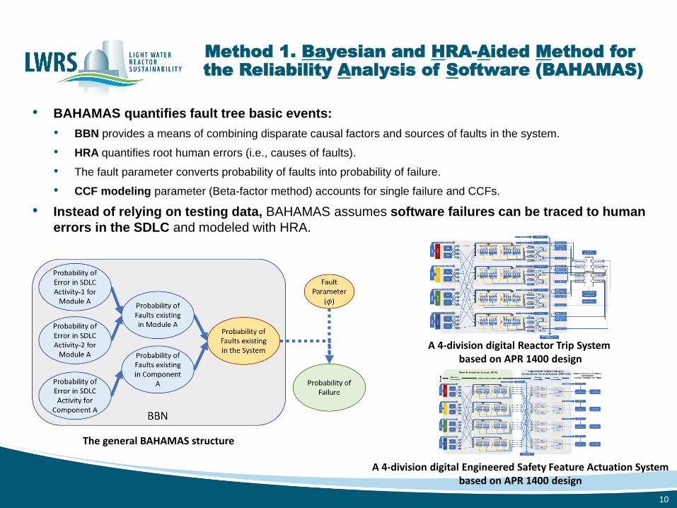
Method 1. Bayesian and HRA-Aided Method for the Reliability Analysis of Software (BAHAMAS)
• BAHAMAS quantifies fault tree basic events:
• BBN provides a means of combining disparate causal factors and sources of faults in the system.
• HRA quantifies root human errors (i.e., causes of faults).
• The fault parameter converts probability of faults into probability of failure.
• CCF modeling parameter (Beta-factor method) accounts for single failure and CCFs.
• Instead of relying on testing data, BAHAMAS assumes software failures can be traced to human
errors in the SDLC and modeled with HRA.
10
The general BAHAMAS structure
A 4-division digital Reactor Trip System based on APR 1400 design
A 4-division digital Engineered Safety Feature Actuation Systembased on APR 1400 design

Method 2. Orthogonal Defect Classification forAssessing Software Reliability (ORCAS)
11
• Compared with BAHAMAS, ORCAS quantifies FT basic events:
• Using sufficient operational and testing data when available.
• Using metric-based and test-based methods to identify software defects.
• Using ODC systematically to link identified defects with potential failure modes.
Workflow of ORCAS
QIAS-P reconstructed architecture based on APR 1400 design
QIAS-P qualified indication and alarm system – safety
SDD software design description
SRS software requirements specifications
STD systems test document
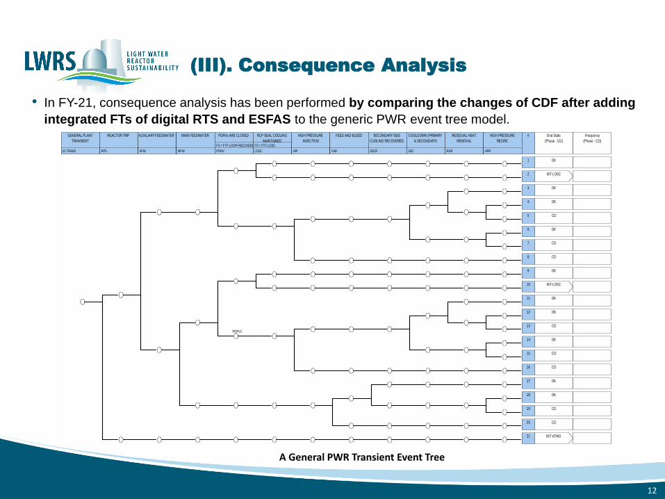
(III). Consequence Analysis
• In FY-21, consequence analysis has been performed by comparing the changes of CDF after adding
integrated FTs of digital RTS and ESFAS to the generic PWR event tree model.
IE-TRANS
GENERAL PLANT
TRANSIENT
RPS
REACTOR TRIP
AFW
AUXILIARY FEEDWATER
MFW
MAIN FEEDWATER
PORV
FS = FTF-LOOP-RECOVERD
PORVs ARE CLOSED
LOSC
FS = FTF-LOSC
RCP SEAL COOLING
MAINTAINED
HPI
HIGH PRESSURE
INJECTION
FAB
FEED AND BLEED
SSCR
SECONDARY SIDE
COOLING RECOVERED
SSC
COOLDOWN (PRIMARY
& SECONDARY)
RHR
RESIDUAL HEAT
REMOVAL
HPR
HIGH PRESSURE
RECIRC
# End State
(Phase - CD)
Frequency
(Phase - CD)
1 OK
2 INT-LOSC
3 OK
4 OK
5 CD
6 OK
7 CD
8 CD
9 OK
10 INT-LOSC
PORV1
11 OK
12 OK
13 CD
14 OK
15 CD
16 CD
17 OK
18 OK
19 CD
20 CD
21 INT-ATWS
12
A General PWR Transient Event Tree

# Prob. Total % Cut Sets1 1.610E-6 37.55 RPS-BME-CF-RTBAB2 1.343E-6 31.33 RPS-CCP-TM-CHA, RPS-TXX-CF-6OF8, RPS-XHE-
XE-NSIGNL3 1.210E-6 28.22 RPS-ROD-CF-RCCAS4 1.040E-7 2.43 RPS-UVL-CF-UVDAB, RPS-XHE-XE-SIGNL5 2.052E-8 0.48 RPS-CCP-TM-CHA, RPS-TXX-CF-4OF6, RPS-XHE-
XE-NSIGNLTotal 4.288E-6 100 -
Original and New Fault Trees for Reactor Trip System
13
Main FT of improved RTS-FT using IRADIC
Main FT of original RTS-FT in the generic PWR SAPHIRE model
Cut sets for the original RTS-FT
# Prob. Total % Cut Sets1 1.210E-6 95.25 RPS-ROD-CF-RCCAS
2 2.052E-8 1.62RPS-CCP-TM-CHA, RPS-TXX-CF-4OF6, RPS-XHE-XE-NSIGNL
3 1.976E-8 1.56 RPS-XHE-XE-SIGNL, RTB-SYS-2-HD-CCF4 1.976E-8 1.56 RPS-XHE-XE-SIGNL, RTB-SYS-1-HD-CCFTotal 1.270E-6 100 -
Cut sets for the new RTS-FT

Original and New Fault Trees for ESFAS
14
Comparison of the top events with original ESFAS-CCF basic event and improved ESFAS-FT
Main FT of HPI failure in the generic PWR SAPHIRE model where CCF of analog ESFAS is considered.
Cut sets for the new ESFAS-FT
• In the original generic PWR SAPHIRE model, ESFAS failure is presented using a CCF of the ESF actuation signals in both
Train A and B (a 2-division ESFAS).
• Compared with the original ESFAS-FT, the new ESFAS-FT has:
• A complicated logic to match the 4-division digital ESFAS structure deployed in APR-1400.
• A significantly reduced failure probability.
• Software CCFs in the new ESFAS-FT do not significantly affect the reliability of digital ESFAS because of the high-
redundant design and high reliability of PLC-based digital systems.
• All the failure probabilities of these safety features have been reduced due to the decrease of ESFAS failure
probability.
FT Name Prob. # of Cut SetsNew ESFAS-FT 2.600E-5 13Original ESFAS-FT 6.420E-4 1
Top EventProbability # of Cut SetsOriginal New Original New
Failure of AFW 1.487E-5 1.240E-5 1539 1551Failure of AFW-ATWS 2.367E-4 2.343E-4 906 918Failure of HPI 1.104E-5 9.803E-6 1163 1172Failure of LPI 8.416E-4 2.258E-4 1567 1579

CDF Reduction by Adding Digital RTS and ESFAS Fault Trees into Event Trees
15
Using IRADIC technology shows deploying advanced digital RTS and ESFAS provides great benefits to plant safety through an
increased safety margin to accident management
Event Trees Original CDF New CDF ∆ CDF ∆ CDF/ Original CDF
INT-TRANS 1.073E-6 5.795E-7 - 4.935E-7 - 46%
INT-SLOCA 7.784E-8 7.512E-8 - 2.720E-9 - 3.4%
INT-MLOCA 6.279E-7 5.032E-7 - 1.247E-7 - 20%
• Results show the CDFs have been greatly reduced.
• By adding the integrated FTs of the 4-division digital RTS and ESFAS into the PRA models, the safety
margin increased by the digitalization of HSSSR I&C systems are quantitatively estimated.
• RTS failure probability is half-reduced from 4.288E-6 to 1.270E-6.
• LPI (low-pressure injection) failure probability greatly decreases from 8.416E-4 to 2.258E-4 due to the improvement of
ESFAS fault tree.

• INL-IRADIC Technology aims to:
• Develop a best-estimate, risk-informed capability to estimate quantitatively and accurately the safety margin obtained
from plant digitalization, especially for the high safety-significant safety-related (HSSSR) DI&C systems.
• Construct a modularized platform for I&C designers, software developers, plant engineers, and risk analysts to
efficiently estimate and prevent the risk introduced by CCFs, especially software CCFs.
• Provide technical basis and risk-informed insights to assist NRC and industry in formalizing licensing processes
relevant to addressing CCF issues in HSSSR DI&C systems.
• Be an integrated risk-informed tool for vendors and utilities to meet the regulatory requirements and optimize the D3
applications in the design stage of HSSSR DI&C systems.
• Demonstration results show digitalization of HSSSR I&C systems (e.g., digital RTS and ESFAS)
provides great benefits to plant safety through an increased safety margin to accident management.
• Future work in FY-22 includes:
• Building up the capability of software CCF modeling and embeding it into the IRADIC technology.
• Improving the methodology and demonstration of IRADIC-ORCAS method.
• Performing uncertainty quantification and validation to better support the best-estimate prediction of safety margins
(e.g., ∆CDF) obtained by the deployment of DI&C systems.
Summary
16

http://lwrs.inl.gov