Embed Size (px)
Citation preview

March 2007 Publication Number 01-XXXX-XX
QUANTIMA SERIES ICP

2 GBC Quantima Operation Manual
Copyright GBC Scientific Equipment Pty Ltd © 2007 All rights reserved Information in this document is subject to change without notice and does not represent a commitment on the part of GBC Scientific Equipment Pty Ltd. No part of this publication may be reproduced, distributed, transmitted, stored in a retrieval system, or reduced to any electronic medium without the prior consent of GBC Scientific Equipment Pty Ltd. GBC Scientific Equipment Pty Ltd assumes no responsibility for any errors that may appear in this document or any damages arising out of the use or inability of this document. GBC Scientific Equipment Pty Ltd acknowledges the various trademarks and proprietary names of companies and products mentioned in this document. GBC Scientific Equipment Pty Ltd is not affiliated with any of these organizations. No approval or endorsement by the organizations mentioned is intended or given either expressly or by implication. GBC Scientific Equipment Pty Ltd reserves the right to change any in part or all specifications without prior notice. Each GBC Quantima instrument has a unique serial number. Printed in Australia GBC Part Number: 01-XXXX-XX Revision Number: 1.0 Issue Date: April 2007 GBC Scientific Equipment Pty Ltd A.C.N. 005 472 686 12 Monterey Road Dandenong, Victoria 3175, AUSTRALIA Telephone: 61 3 9213 3666 Facsimile: 61 3 9213 3677 URL: http://www.gbcsci.com Email: [email protected]

For your safety
GBC Quantima Operation Manual 9
For your safety

For your safety
10 GBC Quantima Operation Manual
Intended use of the instrument The GBC Quantima is an optical emission inductively coupled plasma spectrometer. Its intended use is to measure the concentration of certain metals in liquid solution.
If the instrument is used in a manner not specified in this manual, the protection provided by the instrument safety features may be impaired.
Instrument positioning The instrument should be located on a level sturdy bench. Unrestricted access to the power switch located on the right side panel should be granted at all times.
Follow the instructions printed near this sign (see below).
Electrical hazards Fuse replacement For continuous protection against fire, replace fuses only with the correct type and current rating as shown on the instrument fuse panel.
High voltages The Quantima electronics uses dangerous voltages. The instrument should be serviced only by service personnel trained by GBC staff and holding a GBC Service Training certificate.
RF radiation The RF generator and torch compartment are fully shielded to reduce RF radiation to safe levels. A system of electrical and mechanical interlocks is provided to protect the user at all times from potentially hazardous situations. It is important that interlocks are not bypassed.
Earthing requirements The Quantima instrument should be earthed by connection to the mains. All power outlets used for the Quantima instrument and accessories should have earth terminals connected to the earth mass in accordance with the local regulations.
WARNING Operating a Quantima instrument without a proper earth connection may endanger the user’s life and automatically voids GBC warranty.
Gaseous emissions The plasma when in operation ionizes the surrounding air and produces some ozone gas. I addition, it produces heat, fumes and possibly some dangerous and toxic compounds from the sample being analyzed.
A fume extraction system is required. The extraction capacity should be at least 6 m3 per minute. See page 28 for details.
The extraction system should be turned on at all times when the plasma is operating.

For your safety
GBC Quantima Operation Manual 11
Gas cylinders and lines NOTES The GBC representative is responsible to ensure that the connectors and line types used conform to the national requirements.
The GBC representative is responsible to carry out leak tests of the gas hoses connected to the equipment on installation and during yearly maintenance operations.
CAUTION Maximum argon supply pressure to the instrument should not exceed 700kPa.
Argon and nitrogen are inert and non-flammable gases, and are not normally dangerous, but can be an asphyxiant in high concentrations in confined spaces, because of the displacement of oxygen. Use only in well ventilated areas.
Compressed gases should always be handled with care. The installation of cylinders should be carried out by a registered gas fitter in accordance with your local regulations. In most countries, gas cylinders are required to be located outside. Use only approved regulators, hoses and fittings. The regulators should be adjustable and fitted with pressure gauges for inlet and outlet pressures.
Shut off the supply at the cylinder overnight.
Always use the correct cylinder. If you are not sure whether or not it is the correct cylinder, do not use it.
Avoid leaks; periodically check that lines and fittings are gas tight using soapy water or pressure drop tests.
Compressed gas Always fasten cylinders to walls or other solid fixtures in a vertical position to protect the cylinders from physical damage.
Keep cylinders cool (storage temperature not to exceed 45οC).
Cryogenic gas Suitable for high volume users. Handling and storage precautions as above. Note also: Some venting of the gas to atmosphere occurs at regular intervals, depending upon usage (up to 10% volume loss may be expected). If draw-off rates are too high, fittings and cylinder walls may become frosted. If this occurs, close down the cylinder valve, or reduce the draw-off rate until the frosting disappears.
UV radiation The plasma emits high intensity ultraviolet radiation. The plasma compartment door is interlocked to prevent plasma start or operation when open. It is fitted with a high density glass filter to allow safe observation of the plasma.

For your safety
12 GBC Quantima Operation Manual
Waste container An open type plastic waste container should be available under the instrument bench. Do not use a glass container, or a closed container. A plastic bucket is ideal for aqueous applications. If using organic solvents, ensure the plastic is compatible with the solvents used.
The waste container should be located in open air (not enclosed in a cupboard).
Waste materials should be disposed of in accordance with national regulations.
Flammable samples Flammable samples should be presented in small vials with a small opening (such as 50-100ml volumetric or a small test tube). Keep the samples away from the plasma as much as possible. Do not store large quantities of solvent in the vicinity of the instrument.
Other precautions Normal laboratory and common sense precautions should be adhered to.
Glassware Avoid injury by taking particular care when changing glassware in the instrument, including torch, spray chamber and nebulizer.
Heat The plasma operates at extreme temperatures. Allow several minutes for the torch compartment to cool after shutting down the plasma before attempting to handle the work-coil and the torch.

Specifications
GBC Quantima Operation Manual 13
Specifications

Specifications
14 GBC Quantima Operation Manual
Environmental conditions The Quantima instrument is suitable for indoor use only.
Air quality GBC accepts no responsibility for damage or lack of performance due to poor operating conditions. The operation of the instrument may be impaired by the presence of dust and/or corrosive vapours. Care should be taken to minimize their effect. This will normally entail a suitably ventilated or air conditioned room, and good laboratory practice in the handling or storage of chemicals.
Outlets from air-conditioning ducts should not be directly over or directed towards the instrument as the air flow may affect results.
Temperature range 10 to 35oC.
Relative humidity 8 to 80%, non condensing.
Altitude Sea level to 2200m
Exhaust system An exhaust system with a 6m3/s minimum capacity is required. See details pages 24 and 28.
Argon supply
Purity Welding grade argon (99.9% pure) is suitable for most ICP applications. High Purity (99.99%) argon may be used for special applications.
High Purity argon has the following specification:
• Argon 99.99% minimum
• Oxygen < 10 ppm
• Nitrogen < 50 ppm
• Carbon dioxide < 5 ppm
• Carbon monoxide < 1 ppm
• Hydrocarbon as CH < 1 ppm
• Hydrogen < 1 ppm
• Moisture < 12 ppm at full pressure
Pressure 500-700 kPa

Specifications
GBC Quantima Operation Manual 15
Flow rates Plasma torch: 10 to 20 l/min.
Entrance optics flush: 1 to 6 l/min.
Maximum total flow 26l/min
Nitrogen purge Purity: 99.99% minimum.
Pressure: 250-350 kPa
Flow: 0.3 to 1 l/min
Connections
Gases
Gas Connector type Pressure
Argon Ryco quick-connect 500 - 700 kPa
Nitrogen ¼” Swagelock ™ 50kPa maximum
Water Plasma coil cooling water:
Pressure 50 kPa max
Flow 100-150 ml/min
Connection by barbed connectors.
Power Instrument: Single phase 220 – 240V, 50 or 60 Hz, 20 A capacity with separate earth line and terminal. Power outlet and matching plug are not supplied by GBC.
Accessories: Single phase, 220 – 240V, 50 or 60 Hz, 10 A capacity. with separate earth line and terminal. Power points required for computer, monitor, printer and accessories.
Earthing All power points connected to the Quantima ICP system should be fitted with an earth terminal connected to a common earth line complying with the local regulations.

Specifications
16 GBC Quantima Operation Manual
Computer and software The instrument software is supplied with the instrument. The computer and operating system are not supplied.
Hardware Pentium or AMD CPU, minimum 256MB RAM, two serial ports, USB ports, and minimum 40 GB data storage capacity.
Software Microsoft Windows ® XP operating system. The Quantima software controls the instrument and accessories.
Data processing Analysis by atomic emission.
Graphics High resolution display of wavelength scans, calibration curves and various instrument parameters. Graphics cursor may be used to obtain numerical information from graphic traces. Zoom function.
Data storage Storage is provided for signal graphics, applications, results, sample labels, weight and dilutions and report headers.
Quality Quality control software satisfying GLP and GMP is supplied as standard.
Report generation Reports may be printed during a run or from stored result files. They may include headings, notes, operating parameters, calibration graphs, sample labels, results and statistics.
Instrument performance
Optics 750 mm Czerny-Turner monochromator.
1800 lines/mm holographic diffraction grating driven by GBC non-linear drive.
Wavelength accuracy better than 15 pm
Resolution 2 pm
Wavelength range 300-800nm in first order, 150-400nm in second order.
Nitrogen purge system for analysis below 190nm.
Plasma viewing: side view with adjustable viewing height 3-20mm above torch.
Specifications
GBC Quantima Operation Manual 17
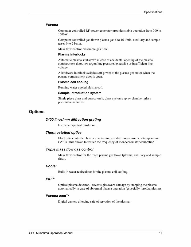
Plasma Computer controlled RF power generator provides stable operation from 700 to 1500W.
Computer controlled gas flows: plasma gas 6 to 16 l/min, auxiliary and sample gases 0 to 2 l/min.
Mass flow controlled sample gas flow.
Plasma interlocks Automatic plasma shut-down in case of accidental opening of the plasma compartment door, low argon line pressure, excessive or insufficient line voltage.
A hardware interlock switches off power to the plasma generator when the plasma compartment door is open.
Plasma coil cooling Running water cooled plasma coil.
Sample introduction system Single piece glass and quartz torch, glass cyclonic spray chamber, glass pneumatic nebulizer
Options
2400 lines/mm diffraction grating For better spectral resolution.
Thermostatted optics Electronic controlled heater maintaining a stable monochromator temperature (35oC). This allows to reduce the frequency of monochromator calibration.
Triple mass flow gas control Mass flow control for the three plasma gas flows (plasma, auxiliary and sample flow).
Cooler Built-in water recirculator for the plasma coil cooling.
PIP™ Optical plasma detector. Prevents glassware damage by stopping the plasma automatically in case of abnormal plasma operation (especially toroidal plasna).
Plasma cam™ Digital camera allowing safe observation of the plasma.
Specifications
18 GBC Quantima Operation Manual
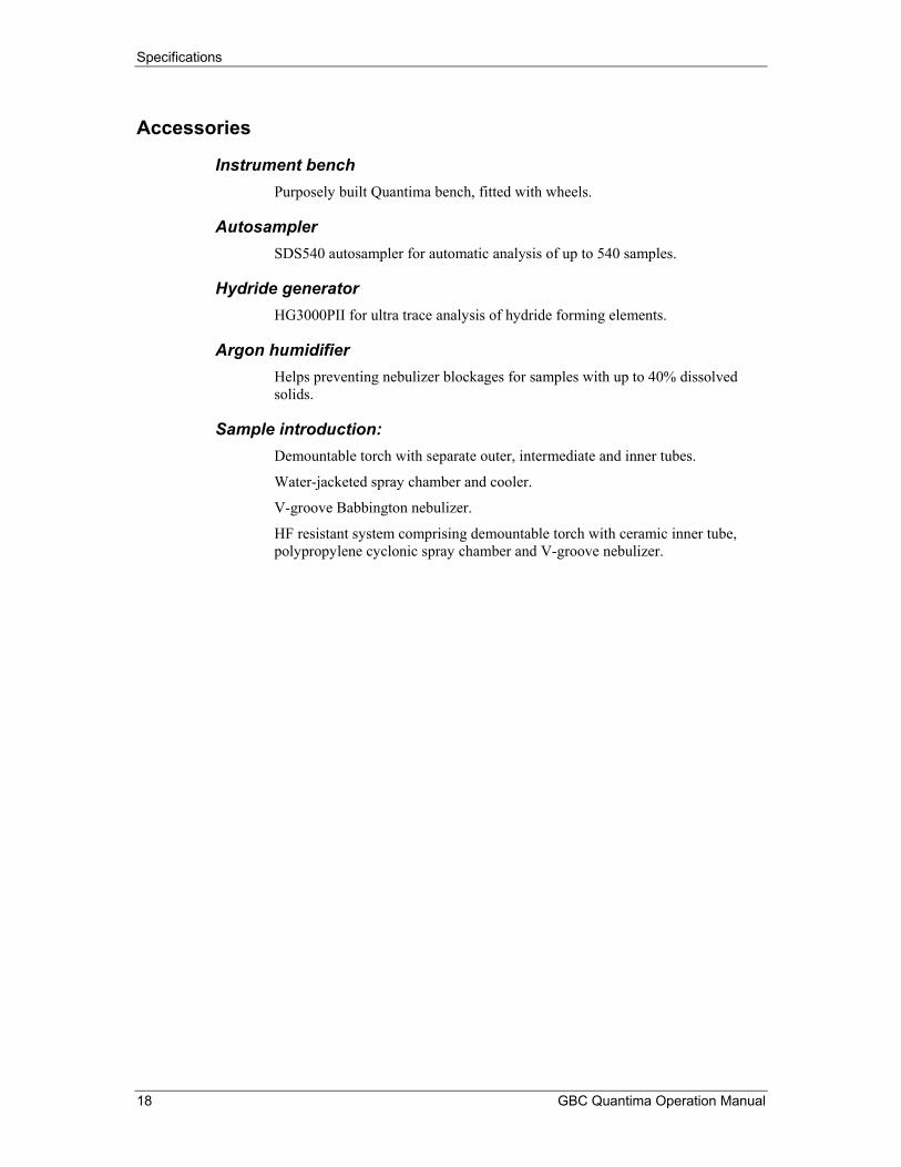
Accessories
Instrument bench Purposely built Quantima bench, fitted with wheels.
Autosampler SDS540 autosampler for automatic analysis of up to 540 samples.
Hydride generator HG3000PII for ultra trace analysis of hydride forming elements.
Argon humidifier Helps preventing nebulizer blockages for samples with up to 40% dissolved solids.
Sample introduction: Demountable torch with separate outer, intermediate and inner tubes.
Water-jacketed spray chamber and cooler.
V-groove Babbington nebulizer.
HF resistant system comprising demountable torch with ceramic inner tube, polypropylene cyclonic spray chamber and V-groove nebulizer.

Specifications
GBC Quantima Operation Manual 19
Performance guarantee The table below indicates:
• The typical and minimum values for the signal to background ratio (SBR)
• The typical and maximum values for the detection limit (DL)
For some metals in aqueous solution with 1% nitric acid.
SBR DL Element Wavelength
Conc. (ppb) Typical Min. Typical Max.
Al 167.081 10000 53 35 2 4Al 396.152 10000 75 50 10 20Cd 214.438 2000 38 25 1 2Cd 228.802 2000 33 22 2 4Cu 224.7 10000 59 39 4 8Cu 324.754 10000 15 10 2 4K 766.49 50000 38 25 30 60Mg 279.553 1000 293 195 0.2 0.4Mg 280.27 1000 150 100 1 2Mg 285.213 1000 29 19 10 20Mn 257.61 1000 33 22 1 2Na 588.995 50000 75 50 5 10Zn 213.856 2000 51 34 1 2
Table 1: Quantima performance guarantee

Specifications
20 GBC Quantima Operation Manual
Weight and dimensions Weight Quantima ICP spectrometer unpacked 250kg, packed 410kg.
Dimensions Spectrometer module: 1518 x 910 x 725 (WxDxH, mm).
Packed instrument: 1810 x 1190 x 1215 (WxDxH, mm).
Footprint Minimum bench space of 900 mm x 2500 mm.

Site preparation
GBC Quantima Operation Manual 21
Site preparation

Site preparation
22 GBC Quantima Operation Manual
Importance of site preparation The importance of the preparation work described in this section cannot be exaggerated. Satisfying all preparation requirements before installation will lay a sound foundation for a smooth installation, which virtually eliminates the likelihood of early equipment failure.
Room requirements
Air quality Refer to Specifications, page 14 for air quality, temperature, pressure and humidity requirements.
Ventilation The instrument ventilation system generates approximately 1500W of heat when the plasma is running (this does not include the heat generated by the plasma itself which must be evacuated from the room by the exhaust system described page 28).
Good instrument location Locate the instrument away from direct sunlight. Do not locate the instrument near a thoroughfare.
The instrument should not be subjected to vibration.
Do not allow air flow from air-conditioning ducts to be directed at the instrument. Ensure that air-conditioning is not turned off at night or on weekends if possible.
Instrument size
1518mm
725mm
910mm
Figure 1: Quantima instrument

Site preparation
GBC Quantima Operation Manual 23
Bench requirements If a fixed bench is used, allow 750 mm space between the bench and the wall to allow easy access to the instrument back panel.
GBC strongly recommends that the bench be mobile. A mobile bench permits fork-lift operations to be carried out in an open space, and the instrument then wheeled into its final location. This will also permit easier access for servicing.
GBC provides a mobile bench (se page 112).
A steel-framed bench with a top of at least 36 mm laminated particle board, or similarly load-bearing material, should be provided by the user. It should be fitted with heavy duty castors (rated at least 75 kg, each) with a brake mechanism to prevent movement of the bench following installation.
The bench should be at least 1500 x 900 mm for the instrument alone, or 2200 x 900 mm if an autosampler is used. It should have a 300kg capacity.
Note also that certain items of necessary ancillary equipment must be accommodated. These include a small desk/workstation for the computer as shown page 24.
Space required
Back panel IMPORTANT NOTE: Good access to the rear panel is necessary once every 4 months for regular maintenance.
If the instrument is installed on a wheeled bench against a wall, allow 150 mm minimum clearance for ventilation and gas connections. The instrument bench must be fitted with wheels.
If the instrument is located on a fixed bench, allow 750 mm minimum space behind the bench.
Left side panel Allow 500mm free space for ventilation.
Right side panel The mains circuit breaker is located on the right side panel and must be easily accessible at all times.

Site preparation
24 GBC Quantima Operation Manual
Typical Quantima workspace
PC Trolley700 x 850
Gas panel Power board
1190mm505mm
500mm minFree space
SDS 540Sampler
Computer
Quantima
Top view
Front view
910mm
100mm
Exhaust
Figure 2: A typical Quantima installation
Figure 2 above shows an installation on a wheeled bench large enough for the Quantima spectrometer and the SDS 540 autosampler side by side.
Allow at least 200mm between the autosampler and the instrument for easy access to the main circuit breaker.
Power requirements
Power points See Specifications page 15

Site preparation
GBC Quantima Operation Manual 25
Earthing requirements The earth terminal of the power outlet to be used for any GBC equipment should be suitably grounded.
WARNING Failure to ensure suitable grounding may endanger the user’s life and will void the instrument warranty.
Earth connection to the instrument is via the green or green/yellow conductor in the power cord. It is not normally necessary to provide special RF grounding, unless this is required by local regulations, or to avoid RFI interference with other ultra-sensitive laboratory instruments.
The earth conductor size should be at least the same size as used for the active neutral wiring, or 2.5 mm minimum. The method used to connect earth conductors to ground should be in accordance with regulations. Please consult your electricity distribution company. Suitable earthing media include the following:
• earthing electrode
• underground water piping system
• metallic sheathing of underground supply cable
Argon supply
Purity See specification page 14.
Pressure A bottle pressure regulator is required to supply a line pressure of 600 kPa to the instrument. Insufficient pressure will inhibit operation.
CAUTION Maximum argon supply pressure to the instrument must not exceed 700kPa
Argon line For short runs (less than 4 metres), 6.5 mm ID PVC high pressure braided hose (NYLEX K9 or equivalent) may be used. For longer runs, 10 mm copper tube is recommended.
The argon line should terminate within 2 metres of the left hand side of the ICP. Terminate the gas line with 1/4" Ryco fittings. GBC ICP instruments are fitted with male Ryco quick-connect gas pressure fittings. A flexible gas line 4 m long is supplied with the ICP instrument for connecting to installed gas line.
Flow rates The torch requires a maximum flow rate of 16 L/min (typical value 11 L/min for sample carrier, auxiliary and plasma gas flows at normal flow rates).
Argon is also used as a flushing gas for the entrance optics if spectral lines in the Vacuum UV region (below 200 nm) are used. Flow rates for flushing are 1–6 L/min.

Site preparation
26 GBC Quantima Operation Manual
Nitrogen supply Oxygen molecules in the air absorb UV radiation below 180nm. To observe UV lines it is necessary to remove oxygen molecules from most of the instrument light path.
In the Quantima instruments a small flow of high purity nitrogen is used to displace the oxygen molecules from inside the optical system. This process is known as nitrogen purge.
Flow diagram
Gassupply
Pressureregulator
Pressuregauge
Meteringvalve
Flowrotameter
ScrubberCheckvalve
N2
Purge kit
To instrumentpurge inlet
Figure 3: Purge system flow diagram
CAUTION The GBC Nitrogen Purge kit is not suitable for direct connection to a Nitrogen gas bottle as the pressures available are too high. A high purity nitrogen gas bottle regulator (with a stainless steel diaphragm) must be attached to the gas bottle to limit the pressure to 800 kPa maximum before connection to the GBC Nitrogen Purge kit.
Summary 1. The Nitrogen Purge Installation kit and any external ¼" Copper tubing lengths must be purchased as accessories to the Quantima instrument.
2. The GBC Nitrogen Purge installation kit consists of an enclosure; pressure regulator & gauge; flow meter & valve; gas purifier; and internal ¼" copper tubing & connections. all these components are housed in a metal enclosure.

Site preparation
GBC Quantima Operation Manual 27
3. Additional ¼" copper tubing needs to be obtained in order to connect the nitrogen gas source to the enclosure, and the enclosure to the Quantima instrument. The lengths of tubing required will need to be determined prior to the installation of the instrument.
4. The correct gas connection or adaptor for attaching the ¼” copper tubing to the Nitrogen bottle or local supply will need to be obtained from local sources (and should satisfy any local requirements and regulations).
Part Numbers :
99-0409-00 Kit, Nitrogen Purged Installation
50-0507-00 Copper, Tube 6.35 mm OD x 20 SWG Annealed (specify total length required in meters)
Layout & dimensions : The following diagrams show the layout and dimensions of the assembled GBC Nitrogen Purge kit, the Nitrogen gas IN and OUT connections, and the mounting holes are indicated for reference.
Figure 4: GBC nitrogen purge kit

Site preparation
28 GBC Quantima Operation Manual
Exhaust system The ICP spectrometer produces heat and some potentially toxic or corrosive gases from the plasma, and heat from the RF generator.
Plasma chimney The plasma chimney must be ducted to the atmosphere (i.e., outside the building). An exhaust fan capacity of at least 6 m3/minute is needed, with a damper control to regulate efficient exhaust without causing instability of the plasma.
A fume extraction system (including a barrel fan and damper control) is available from GBC (Part No. 99-0012-00). The flared skirt (hood) of the ducting must be loosely coupled to the plasma chimney (leave a gap of approximately 10 cm) to prevent too much air being drawn through the plasma compartment. Close coupling will cause the plasma to flutter and may affect analytical results.
See page 24 for exhaust positioning.
920 mm
Suction fan
Vent duct toatmosphere
Allow 100mm gap betweenflue and chimney
Figure 5: Exhaust system
RF generator The RF generator is air cooled and may produce more than 1 kW of heat. This may be exhausted into the room, or ducted to the outside of the building, depending upon local requirements and climatic conditions.

Site preparation
GBC Quantima Operation Manual 29
Pre-installation check list Check that all operations in the table below have been completed beore proceeding with the installation.
Item Description
Space
1.8 m deep (wheeled bench) 2.7 m deep (fixed bench) 3m wide (including 50cm at left). See page 14 for air quality and ventilation requirements
Argon supply Cryogenic or compressed, welding grade argon. See page 14
High purity nitrogen supply and purge kit Compressed. See page 26.
Gas connectors <2m from left panel
Water connectors <2m from left panel. See page 15
Exhaust system 6m3 /min, 10cm above instrument exhaust. See page 28.
Power points 20A for instrument, 10A for computer and peripherals. See page 24.
Instrument bench On wheels, or 0.75m space available behind bench. See page 23
Table 2: Pre-installation check list


![Sensors & Accessories User Manual Sensors & Accessories · 2015. 7. 23. · Connection to measurement circuit [1.2.2→8]). Then switch on the instrument and theequipment,andfinally,afterdoublecheckingthewiring,switchonthemeasurementcircuit](https://img.dokumen.tips/doc/110x75/6147cbafa830d0442101ab18/sensors-accessories-user-manual-sensors-2015-7-23-connection-to.jpg)