Embed Size (px)
Citation preview
United States Office of Air Quality October, 1998Environmental Protection Planning and StandardsAgency Research Triangle Park, NC 27711Air
Quality Assurance Guidance Document
Method Compendium
PM2.5 Mass Weighing Laboratory Standard Operating Proceduresfor the Performance Evaluation Program

FRM PEP Laboratory SOPsOctober, 1998
-ii-
Foreword
The intent of this document is to describe and provide detailed standard operating procedures forthe laboratory activities of the PM2.5 Federal Reference Method Performance Evaluation Program(PEP).
The document was developed with the assistance of various workgroups that will be responsiblefor implementing or overseeing the laboratory aspects of the PEP, as well as State and localorganizations that have a vested interest in the quality of the routine ambient air monitoring data.The personnel involved in these workgroups are listed in the acknowledgments.
This document is available in hardcopy format and as a PDF file on the Internet on the Ambient Monitoring Technology Information Center (AMTIC) Bulletin Board under the PM2.5 QA area(http://www.epa.gov/ttn/amtic/pmqa.html). The PDF document can be read and printed usingAdobe Acrobat Reader software, which is freeware that is available from many Internet sites,including the U.S. EPA web site. The Internet version is write-protected. Hardcopy versions areavailable by writing or calling:
Mark ShanisOffice of Air Quality Planning and StandardsMD-14US EPARTP, NC 27711(919-541-1323)Internet:[email protected]
The document mentions trade names or brand names. Mention of corporation names, tradenames, or commercial products does not constitute endorsement or recommendation for use.

FRM PEP Laboratory SOPsOctober, 1998
-iii-
Contents
Section SOP Number Page
ForewordContentsAcknowledgmentsAcronyms and AbbreviationsTables and Figures
iiiiivvivii
1 Introduction
2 General Laboratory Preparation PEPL-2.01
3. Equipment Inventory and Maintenance PEPL-3.01
4 Communications PEPL-4.01
5 Filter Handling PEPL-5.01
6 Filter Conditioning PEPL-6.01
7 Calibration PEPL-7.01
8 Filter Weighing PEPL-8.01
9 Shipping PEPL-9.01
10 Filter Chain of Custody PEPL-10.01
11 Data Entry and Data Transfer NO Info
12 Quality Assurance/Quality Control PEPL-12.01
13 Storage and Archiving PEPL-13.01
Appendices
A GlossaryB Data Qualifiers/Flags

FRM PEP Laboratory SOPsOctober, 1998
-iv-
Acknowledgments
This Method Compendium of Laboratory Standard Operating Procedures is the product of the combinedefforts of the U.S. EPA Office of Air Quality Planning and Standards, the EPA National ExposureResearch Laboratory, the EPA Regional Offices, and the State and local organizations. The initialdevelopment of this material comes from Robert Wright of RTI. The following individuals areacknowledged for their contributions.
State and Local Organizations
George Apgar, State of Vermont, Waterbury, VTRandy Dillard, Jefferson County Department of Health, Birmingham, ALDennis Mikel, Ventura County APCD, Ventura, CAKevin Goohs, Gordon Pierce, and Pat McGraw, Colorado Dept. of Public Health & Environment, Denver, COAlice Westerinen, Russell Grace, and Tom Pomales, California Air Resources Board, Sacramento, CAJeff Miller, Pennsylvania Department of Environmental Protection, Harrisburg, PARichard Heffern, State of Alaska Department of Environmental Conservation, Juneau, AKDan Harman, North Dakota Department of Health, Bismarck, ND Dave Wallenberg, STAPPA/ALAPCO
EPA Regions Region 1 Norman Beloin, Mary Jane Cuzzupe, Tony Palermo
2 Clinton Cusick, Dick Coleates3 Victor Guide, Theodore Erdman, Fred Foreman4 Jerry Burger, Herb Barden, Mike Birch5 Mary Ann Suero, Gordon Jones, Mike Rizzo, Basim Dihu, Jay Thakkar6 Mary Kemp, Mark Sather, Kuenja Chung, Timothy Dawson, Ruth Tatom, Melvin Ritter7 Leland Grooms, Mike Davis, Shane Munsch, Harold Brown8 Ron Heavner, Gordan MacRae, Joe Delwiche, Barbara Daboll9 Mathew Plate, Manny Aquitania, Bob Pallarino, Rose Fong10 Barrry Towns, Karen Marasigan, Bill Puckett, Gerald Dodo
National Exposure Research Laboratory
Frank McElroy, David Gemmill
ESAT Organization
Monica McEaddy, Kathleen Engel, Angela Edwards, Colleen Walling, Sam Jamison
Research Triangle Institute
Robert Wright, Cynthia Salmons, Adrianne Leinbach
Office of Air Quality Planning and Standards
Tim Hanley, David Musick, Mark Shanis

FRM PEP Laboratory SOPsOctober, 1998
-v-
Acronyms and Abbreviations
AIRS Aerometric Information Retrieval SystemAPTI Air Pollution Training InstituteCFR Code of Federal RegulationsCMD Contracts Management DivisionCO Contracting OfficerCOC chain of custodyCS Contracting SpecialistDAS data acquisition systemDQA data quality assessmentDQOs data quality objectivesEDO environmental data operationEMAD Emissions, Monitoring, and Analysis DivisionEPA Environmental Protection AgencyESAT Environmental Services Assistance TeamFEM Federal Equivalent MethodFRM Federal Reference MethodGLP good laboratory practiceLA laboratory analyst (ESAT contractor)LAN local area networkMQAG Monitoring and Quality Assurance GroupMQOs measurement quality objectivesNAAQS National Ambient Air Quality StandardsNAMS national air monitoring stationNERL National Exposure Research LaboratoryNIST National Institute of Standards and TechnologyOAQPS Office of Air Quality Planning and StandardsOAM Office of Acquisition ManagementOARM Office of Administration and Resources ManagementORD Office of Research and DevelopmentPC personal computerPE performance evaluationPEP Performance Evaluation ProgramPM2.5 particulate matter < 2.5 micronsPO Project Officer (Headquarters)PTFE polytetrafluoroethyleneQA/QC quality assurance/quality controlQA quality assuranceQAPP quality assurance project planQMP quality management planRPO Regional Project OfficerSLAMS state and local monitoring stationsSOP standard operating procedureSOW statement or scope of workSTAG State and Tribal Air GrantsTSA technical systems auditWAM Work Assignment Manager

FRM PEP Laboratory SOPsOctober, 1998
-vi-
Tables
Number Section Page
1-1 Required Reading for the Performance Evaluation 1 8Program
3-1 Equipment/Consumable Inventory 3 33-2 Maintenance Requirements 3 54-1 Communications Summary 4 64-2 Implementation Summary 4 74-3 Filter Estimates 4 74-4 Monthly Filter Preparation Estimates 4 84-5 ESAT Contacts 4 1112-1 Acceptance Criteria for Laboratory QC Checks 12 212-2 Laboratory QC Check Parameters 12 613-1 PM2.5 PEP Laboratory Filing System 13 4
Figures
1.1 Definition of independent assessment 1 31.2 Performance evaluation program implementation 1 4
summary4.1 Line of communication 4 24.2 Critical filter holding times 4 68.1 Filter cassette equipment and filter cassette in 8 10
antistatic sample bag9.1 Filter preparation/shipment requirements 9 3

PM2.5 Performance Evaluation Program Laboratory SOPsSection 1
Date:10/30/98Revision: Final Draft
Page: 1 of 8
1.0 INTRODUCTION
The purpose of this section is to provide the ESAT laboratory analyst (LA) with backgroundinformation on the PM2.5 Program, and the Federal Reference Method Performance EvaluationProgram (PEP) as an introduction to standard operating procedures (SOPs) for laboratorypersonnel involved in the PEP.
PM2.5 Program
In general, the measurement goal of the PM2.5 Ambient Air Quality Monitoring Program is toestimate the concentration, in units of micrograms per cubic meter (Fg/m3 ), of particulates ofaerodynamic diameters less than or equal to 2.5 micrometers (Fm) that have been collected on a46.2mm polytetrafluoroethylene (PTFE) filter in a FRM sampler. In order to understand the sizeof 2.5 Fm, a human hair is approximately 50 Fm in diameter. One major objective for thecollection of this data is to compare the PM2.5 concentrations to the annual (15.0 Fg/m3 annualarithmetic mean concentration) and 24-hour (65 Fg/m3 24-hour average concentration) NationalAmbient Air Quality Standard (NAAQS). A description of the NAAQS and its calculation canbe found in the July 18, 1997 Federal Register Notice. In addition, Appendix L of 40 CFR part50 also provides the following summary of the measurement principle:
“ An electrically powered air sampler draws ambient air at a constant volumetric flow rate into aspecially shaped inlet and through an inertial particle size separator (impactor) where the suspendedparticulate matter in the PM2.5 size range is separated for collection on a polytetrafluoroethylene(PTFE) filter over the specified sampling period. The air sampler and other aspects of this referencemethod are specified either explicitly in this appendix or generally with reference to other applicableregulations or quality assurance guidance.
Each filter is weighed (after moisture and temperature equilibration) before and after sample collectionto determine the net weight (mass) gain due to collected PM2.5. The total volume of air sampled isdetermined by the sampler from the measured flow rate at actual ambient temperature and pressureand the sampling time. The mass concentration of PM2.5 in the ambient air is computed as the totalmass of collected particles in the PM2.5 size range divided by the actual volume of air sampled, and isexpressed in micrograms per actual cubic meter of air (Fg/m3 ).”
The Federal Reference Method (FRM )Performance Evaluation Program(PEP)
Since the data for the State and Local Air Monitoring Stations and National Air MonitoringStations (SLAMS/NAMS) network are used for NAAQS comparisons, the quality of this data arevery important. Therefore, a quality system has been developed to control and evaluate thequality of data in order to make NAAQS determinations within an acceptable level of confidence.During the development of the PM2.5 NAAQS, the EPA used the data quality objective process todetermine the allowable measurement system imprecision and bias that would not significantly

PM2.5 Performance Evaluation Program Laboratory SOPsSection 1
Date:10/30/98Revision: Final Draft
Page: 2 of 8
effect a decision makers ability to compare pollutant concentrations to the NAAQS. Theprecision requirement (10%CV) and bias requirement ( +10%) are based on total measurementuncertainty, which incorporates errors coming from all phases (field sampling, handling, analysisetc.) of the measurement process. The collocated samples provide adequate estimates ofprecision. The FRM Performance Evaluation, if properly implemented, can provide the biasestimate.
The PEP is a quality assurance activity which will be used to evaluate measurement system biasof the PM2.5 monitoring network. The pertinent regulations for this performance evaluation arefound in 40 CFR Part 58, Appendix A, section 3.5.3. The strategy is to collocate a portable FRMPM2.5 air sampling instrument within 1 to 4 meters of a routine NAMS/SLAMS PM2.5 airmonitoring instrument, operate both monitors, and then compare the results.
The implementation of the FRM Performance Evaluation is a State/local responsibility. However,due to a number of comments made during the review period for the December 13, 1997 PM2.5
NAAQS Proposal, the Agency assessed the FRM PEP and consequently made the followingrevisions:
< modified the system to include an independent FRM Performance Evaluation;< reduced the burden of this program by changing the audit frequency from all sites to 25%
of the PM2.5 sites;< reduced the audit frequency from six times a year to four times a year; and< made allowances to shift the implementation burden from the State and local agencies to
the federal government.
A performance evaluation is defined as a type of audit in which the quantitative data generated ina measurement system are obtained independently and compared with routinely obtained data toevaluate the proficiency of the an analyst or laboratory. In the case of the PEP, the goal is toevaluate total measurement system bias, which includes measurement uncertainties from the fieldand the laboratory activities. Independent assessment (Figure 0.1) was defined by the PM2.5 QAWorkgroup in order to ensure that an appropriate level of independence is maintained duringState and local implementation of the PEP.
The implementation goal of the PM2.5 program is to establish a national monitoring network byDecember 31, 1999. These sites includes those using FRM/FEM samplers, sites employingcontinuous analyzers, chemical speciation sites, visibility measurement sites, and special purposemonitoring sites. Each year 25% of the SLAMS/NAMS monitors will be identified forperformance evaluations at a frequency of 4 times per year.
During the months of August through October, 1997 the EPA discussed the possibility of FederalImplementation with the EPA Regions, SAMWG and various State and local organizations(NESCAUM, MARAMA, WESTAR, individual organizations). The majority of the responsesfrom these organization were towards federal implementation.

PM2.5 Performance Evaluation Program Laboratory SOPsSection 1
Date:10/30/98Revision: Final Draft
Page: 3 of 8
Organization
3rd Level
Supervision
Organization
2nd Level
Supervision
Organization
1st Level
Supervision
Organization
Personnel
QA Lab Analysis
Organization
1st Level
Supervision
Organization
Personnel
QA Field Sampling
Organization
2nd Level
Supervision
Organization
1st Level
Supervision
Organization
Personnel
Routine Lab Analysis
Organization
1st Level
Supervision
Organization
Personnel
Routine Field Sampling
Figure 1
Independent Assessment - an assessment performed by a qualified individual, group, ororganization that is not part of the organization directly performing and accountable forthe work being assessed. This auditing organization must not be involved with thegeneration of the routine ambient air monitoring data. An organization can conduct theFRM PE if it can meet the above definition and has a management structure that, at aminimum, will allow for the separation of its routine sampling personnel from its auditingpersonnel by two levels of management, as illustrated below. In addition, the pre- andpostsample weighing of audit filters must be performed by a separate laboratory facilityusing separate laboratory equipment. Field and laboratory personnel would be requiredto meet the FRM PE field and laboratory training and certification requirements.
Figure 1.1. Definition of independent assessment
EPA investigated potential contracting mechanisms to assist in the implementation of this activityand will use the Environmental Services Assistance Team (ESAT) contract currently in place ineach Region to provide the necessary field and laboratory activities. Each EPA Region will

PM2.5 Performance Evaluation Program Laboratory SOPsSection 1
Date:10/30/98Revision: Final Draft
Page: 4 of 8
Region 4 & 10 Lab
OAQPS
AIRS
1 new filters
Regions 1-10 Field Work
Filter
s
CHAINOF
CUSTODY&
FIELDFORMS
2CHAIN
OFCUSTODY
CHAINOF
CUSTODY&
FIELDFORMS
CHAINOF
CUSTODY&
FIELDFORMS
3
4
Field
validated data5
4
Figure 1.2 Performance Evaluation Program implementation summary
implement the field component of this activity, while Regions 4 and 10 will also operate thelaboratory component.
1.2.3 PEP Activities
The FRM PEP can be segregated into a laboratory component and a field component, followed bydata validation and analysis, and then reporting. The following information provides a briefdescription of these activities. Figure 1.2 provides a basic description of the PEP in five steps:
1. EPA will send filters to Region 4 and 10 laboratories, where they will be checked, equilibrated, labeled, weighed, and prepared for the field.
2. Regions 4 and 10 will ship the filters and accompanying chain of custody (COC) to the Regional field offices.
3. The field scientist will take the filters, field data sheet, and COC to the field andoperate the portable samplers.
4. The field scientist will return the filter, data diskettes, field data sheet and COC to theappropriate laboratory (as well as keep a set of the data and records).
5. Region 4 and 10 laboratories will equilibrate and weigh filters, validate data, andupload information to the Aerometric Information Retrieval system (AIRS).
Field Activities:
The FRM portable auditsamplers will be used in acollocated manner toperform the evaluations. These samplers have beenapproved by EPA as aFederal Reference Methodand are designed to bedurable, rugged, and capableof frequent transport. Thesesamplers are constructed inmodules with each moduleweighing no more than 40pounds. The total weight ofthe sampler itself must notweigh more than 120pounds. While thesesamplers have beenspecifically designed toperform these evaluations,precautions must be taken

PM2.5 Performance Evaluation Program Laboratory SOPsSection 1
Date:10/30/98Revision: Final Draft
Page: 5 of 8
to ensure the quality of the data. Specific detailed instructions will be found in the PEP QualityAssurance Project Plan (QAPP) and SOPs. A brief summary of the field activities follows:
1. One fully trained field scientist will transport a portable PM2.5 FRM PE sampling device toan established PM2.5 site, which shall be located at any of the SLAMS/NAMS sites withineach EPA Region.
2. The field scientist will assemble, collocate the sampler, perform a calibration verificationfollowing the SOPs, install a filter and operate the sampler at the required 24-hoursampling schedule (midnight to midnight).
3. If scheduling allows, the field scientist will leave this location to set up an additional 24-hour PE at another SLAM/NAMS sampling location. If the schedule does not allow foranother setup, the field scientist may perform additional activities at the site. The fieldscientist may also perform any required maintenance or repair of the portable PM2.5
sampling device followed by a verification to ensure the previous calibration remainsvalid..
4. The field scientist will return to each site after the 24-hour sampling time, download thestored electronic monitoring data, remove and properly store the filter for transport, anddisassemble the instrument.
5. The field scientist will properly package the filter, following the SOPs, for transport to thepre-determined laboratory.
Laboratory Activities:
The FRM PE also requires extensive laboratory activities, including filter handling, equilibration,weighing, data entry/management and archival. Regions 4 and 10 will develop the laboratoriesfor this program. Specific detailed instructions will be found in the PEP QAPP and this SOP. Inaddition to the good laboratory practices that must be followed, the following activities must alsobe observed:
< adherence to the vendor’s operations manual for the proper operation of the weighingdevices; including proper set-up, calibration, and operation of the microbalances;
< adherence to the Standard Operating Procedures (SOPs) for the program;< adherence to the standards, principles, and practices outlined in the PEP QAPP;< completion of the required certification training program; and< giving special attention to any activity involving filter handling (pre-sampling equilibration,
weighing, postsampling equilibration, transport, etc.). This area contains the greatestpotential for measurement uncertainty, and care must be given to the proper handling ofthe 46.2-mm Teflon® filter used in the PE.

PM2.5 Performance Evaluation Program Laboratory SOPsSection 1
Date:10/30/98Revision: Final Draft
Page: 6 of 8
Presampling weighing:
1. Filters will be received from EPA and examined for integrity based upon EPA approved SOPs.
2. Filters will be enumerated for data entry.3. Filters will be equilibrated and weighed according to SOPs.4. Filters will be prepared for field activities or stored according to SOPs.5. The Laboratory will develop and maintain the shipping/receiving of supplies and
consumables, including containers, ice substitutes maximum/minimum thermometers, andCOC requirements and documentation.
Postsampling weighing:
1. Filters will be received in the laboratory, checked for integrity (damage-temperature), andlogged in.
2. Filters will be archived (cold storage) until ready for weighing.3. Filters will be brought into the weighing facility and equilibrated for at least 24 hours (per
SOPs).4. Filters will be weighed according to SOPs and data entered.5. Field data will be entered into the data entry system to calculate a concentration.6. Filters will be stored in archive for 1 year at ~4 oC and 2 years at ambient temperature.7. Required data will be transferred to the AIRS database.
1.3 Purpose of this Document
These FRM PEP Laboratory SOPs provide the detailed procedures to be followed whenperforming the following laboratory activities, which follow this section as the Lab SOPSection Titles:
< 2.0 General Lab Preparation< 3.0 Equipment Inventory/Maintenance < 4.0 Communications (Regions/ State and locals)< 5.0 Filter Handling< 6.0 Filter Conditioning< 7.0 Calibration< 8.0 Filter Weighing< 9.0 Filter Shipping< 10.0 Filter Chain of Custody< 11.0 Data Entry/Transfer< 12.0 QA/QC < 13.0 Storage/Archive

PM2.5 Performance Evaluation Program Laboratory SOPsSection 1
Date:10/30/98Revision: Final Draft
Page: 7 of 8
All methods are to be followed completely. Any deviation must be reported in writing andsubmitted to the ESAT Work Assignment Manager (WAM). Method improvements areencouraged. If any deviations or modifications offer a more efficient method/technique orserve to maintain/improve data quality, these proposed changes shall be made in writing to theESAT WAM.
Each section will be written as a stand alone procedure that will assist in training andcertification activities and can be removed from the document and made readily available at thestation where the activity takes place. The SOPs follow the format of the guidance entitledGuidance for the Preparation of Standard Operating Procedures (SOPs) EPA QA/G-6 fortechnical SOPs. The QA/G6 requirements include the following topics as Titles:
A. Scope and ApplicabilityB. Summary of MethodC. Definitions (acronyms, abbreviations and specialized forms used in the SOPs)D. Health & Safety WarningsE. CautionsF. InterferencesG. Personnel QualificationsH. Apparatus and MaterialsI. Instrument or Method CalibrationJ. Sample CollectionK. Handling and PreservationL. Sample Preparation and AnalysisM. TroubleshootingN. Data Acquisition, Calculations and Data ReductionO. Computer Hardware and SoftwareP. Data Management and Records Management.
Each method will address only those topics that are relevant for that method. Themethods will be numbered as follows:
PEPL-X.YYWhere:
PEPL indicates the Performance Evaluation Program Laboratory SOPs,X indicates the section where the method is found (based on the table of contents),
andYY indicates the method number.

PM2.5 Performance Evaluation Program Laboratory SOPsSection 1
Date:10/30/98Revision: Final Draft
Page: 8 of 8
1.4 Prerequisites
1.4.1 Training and Certification
All laboratory personnel funded by the ( Office Of Air Quality and Planning and Standards(OAQPS) PEP work assignment (WA) must be trained and certified to perform the activities.Training and recommendation for certification can be provided by the Regional WAM orOAQPS.
1.4.2 Background Reading
Prior to implementing laboratory activities, laboratory personnel are expected to be familiarwith the documents listed in Table 1-1. The knowledge level is rated from 1, being veryknowledgeable to 5, having a basic understanding.
Table 1-1. Required Reading for the Performance Evaluation Program
Document Knowledge
FRM Performance Evaluation Program Laboratory SOPsFRM Performance Evaluation Program QA Project PlanFRM Performance Evaluation Program Implementation PlanPM2.5 Data Quality Objectives Process FRM Performance Evaluation Program Field SOPsQA Handbook, Vol. II, Part 140 CFR Part 50, Appendix L40 CFR Part 58, Appendix A
12223344
1.5 Definitions
Appendix A contains a glossary of the terms in the PEP. Acronyms are in the front of thedocument.
1.6 Cautions
The filters used for the PM2.5 sampler are comparatively small, each weighing about 150milligrams (mg). Because of the size and weight of the particles that will be collected on thesefilters, net weights will be measured in micrograms (Fg). The loads on the filter may beanywhere from 20 to 2000 Fg (83 Fg/m3) with most sample loads around 300 Fg. To put thisweight in perspective, a 4-centimeter long human hair weighs ~312 Fg. This 300 Fg valuerepresents ~0.2% of the weight of the blank filter. In addition, it is expected that the LA willbe able to duplicate weighings of the same filter to within 15 Fg. A single thumbprint on afilter weighs 15 Fg. It should be apparent that any small loss or gain (i.e., finger oils, dust) willaffect filter weights. Additional details of filter handling are discussed in Section 4.

FRM PEP Lab SOP Section 2PEPL-2.01
Date: 10/30/98Revision: Final Draft
Page 0 of 12
Weighing Laboratory Standard Operating Procedurefor the PM2.5 FRM Performance Evaluation Program
Section 2.0
General Laboratory Preparation

FRM PEP Lab SOP Section 2PEPL-2.01
Date: 10/30/98Revision: Final Draft
Page 1 of 12
Weighing Laboratory Standard Operating Procedurefor the PM2.5 FRM Performance Evaluation Program
Operation: General Laboratory Preparation
SOP: PEPL-2.01
Name: Printed Signature Date
Mark Shanis
Contents (applicable to this SOP)
Section Page
1. Scope and Applicability 22. Summary of Method 23. Definitions 34. Health and Safety Warnings 35. Cautions 46. Interferences 57. Personnel Qualifications 68. Apparatus and Materials 69. Laboratory Preparation Procedures 710. Troubleshooting 911. Data Acquisition and Calculations 10

FRM PEP Lab SOP Section 2PEPL-2.01
Date: 10/30/98Revision: Final Draft
Page 2 of 12
1.0 Scope and Applicability
This SOP describes the process to select and set up a weighing and conditioning area within anenvironment designed to:
< minimize sources of contamination< isolate filters and balance(s) from forces and environmental conditions affecting
microbalance measurement stability and variability< maintain the temperature of the conditioning air to a mean of 20 to 23 EC, controlled to
±2 EC over a 24-hour period< maintain the relative humidity(RH) to a mean of 30 to 40%, controlled to ±5% RH over
24 hours< maintain clean surfaces for exposing new filters, loading or unloading cassettes and
storing filters when they are not being weighed or sent to or returned from the field< in general, prepare the laboratory for activities required in the PEP
2.0 Summary of Method
The laboratory used for the conditioning and weighing of filters will have enough space to:
< condition the required number of filters< house the microbalance, temperature and humidity recording instruments, bar code
readers, and data recording devices (computer) in a manner that does not affect dataquality
< distinguish filters at various stages of preparation and weighing< prepare filters for shipping.
The room will meet temperature and humidity requirements, be kept free of sources ofcontamination, and be maintained in an acceptable state of cleanliness. This SOP assumes that thePM2.5 filter laboratory has been established.
Acceptable control of conditions listed in 1.0 are determined by testing for and determiningseveral parameters. Microbalance performance is estimated by determining the detection limit forsmall loads as compared to background noise and much larger filter weights.
The data for determining sensitivity by DL are simulated by measuring external standard weightswhich are more stable to weigh then the filters.
Balance stability is estimated by the time required to achieve stable standard weight values (10–20seconds) and if the mean difference is less than 3 ug and the overall DL is less than or equal to 5ug.

FRM PEP Lab SOP Section 2PEPL-2.01
Date: 10/30/98Revision: Final Draft
Page 3 of 12
3.0 Definitions
Appendix A contains a glossary of terms used for the PEP. Acronyms are listed in the front ofthis document. However, the terms conditioning room and laboratory are used synonymouslythroughout this document.
4.0 Health and Safety Warnings
To prevent personal injury, employees must heed all warnings associated with operation ofmicrobalances, and their supporting equipment and supplies. Specific health and safety warningswill generally be found at the point in the operating manual or troubleshooting guide where theyare most applicable. In general, health and safety warnings will fall into these three categories:
< electrical,< chemical, and< equipment placement and stability.
Electrical safety considerations that apply to PM2.5 laboratory operations include the following:
< Make all electrical connections in accordance with national codes. Always use a third wiregrounding arrangement on the microbalance and on any electrical appliances. To minimizethe possibility of electrical shock and injury, always use a grounded outlet and cord. Thisprocess avoids the possibility of electrocution.
< Electrical supply lines to the PM2.5 laboratory must be installed so that they remain dryunder all weather conditions and are protected from exposure to extremes of light andheat, which will degrade the covering and insulation. Inspect the electrical cords andconnections for signs of wear and have an electrician repair or replace them as needed.
< Always unplug the power to laboratory instruments when servicing or replacing parts inareas requiring removal of protective panels.
Chemical safety considerations that apply to PM2.5 laboratory operations include the following:
< All chemicals and hazardous material used in the laboratory should come with materialsafety data sheets (MSDS). Post these, or have them in an area that is readily available.
< Use care in the application of cleaning solvents. Use of gloves is recommended. Washhands thoroughly after working with chemicals. Provide good ventilation if organicsolvents are used. Dispose of chemicals and shop towels properly.
< Mercury metal, a poisonous material, is present in some types of thermometers,barometers, and RH indicators. If liquid mercury is spilled, it must be cleaned up anddisposed of properly. Use protective equipment to avoid inhalation of vapors andimpermeable gloves to avoid skin contact. Mercury cleanup kits are available. Locate

FRM PEP Lab SOP Section 2PEPL-2.01
Date: 10/30/98Revision: Final Draft
Page 4 of 12
mercury-containing devices in areas that are physically, structurally, and aerodynamicallyisolated from human workstations.
< Exercise caution when using antistatic devices containing radioactive polonium sources.Keep an inventory of the location and size of antistatic devices. Dispose of the devices inaccordance with manufacturers specifications and State and local regulations.
Equipment safety considerations that apply to PM2.5 laboratory operations include the following:
< Ensure that doors can open without banging into furniture equipment.< Ensure that doors can open from the inside.< Avoid placing shelves above head height or where personnel must reach over obstructions
(e.g., desks ) in a manner that they could and lose balance.< Ensure that the design and performance of the weighing /conditioning room meet the
facility Health and Safety Officer’s minimum requirements for providing breathable air foremployees entering and using the room. In general, the requirement can be met by analarmed, feedback loop or equivalent throttle control of % of make-up(fresh air) whichadds more fresh air when the CO2 concentration rises above (2000ppm) and the oxygenconcentration falls below the proportions considered acceptable for human respiratoryneeds. An example of such a make-up air throttle system is the inexpensive Gaztech®sensor/control made by Telaire.
The laboratory must be designed in a manner that alarm systems can be heard. Fire suppressionequipment should comply with local building codes, State/Federal OSHA regulations and NationalFire Codes.
5.0 Cautions
Relative humidity is a difficult parameter to control; even if total moisture content stays constant,if temperature changes RH will also change. Be prepared to control for seasonal extremes (suchas high heat and humidity in the summer) by using supplemental equipment (i.e., asdehumidification in the summer) during the extremes.
Personnel should always wear clean clothes and wash thoroughly all parts of their body that maybe exposed during weighing, especially hands, arms, face, and hair, using adequate soap and waterto remove loose skin and hair, as close as possible to the weighing activity. The use of laboratorycoats and gloves are required and will minimize the potential for laboratory contamination.Laboratory coats must be taken off before leaving the weighing facility to minimize contaminationfrom the external environment.

FRM PEP Lab SOP Section 2PEPL-2.01
Date: 10/30/98Revision: Final Draft
Page 5 of 12
6.0 Interferences
< An important limitation of the method involves changes in the weight of a collectedsample due to mishandling, chemical reactions, and volatilization.
< Handling procedures, humidity and temperature control of the filter and sample duringweighing, and promptness in and consistency of the weighing method prior to andfollowing collection all help control artifacts.
< The chemical makeup of the PM2.5 particulate matter will vary with the sampling locationand the source. Thus, the magnitude of PM2.5 weight changes due to chemical and physicalprocesses will also vary with site location, day of the week, and season of the year.
< If nitric acid vapor is present at a sampling location, it can deposit on a Teflon® filter andcause small weight gains in proportion to the amount of nitric acid present in theatmosphere. This weight gain may not be controllable.
< Weight losses can occur due to thermal or chemical decomposition or evaporation ofcompounds like ammonium nitrate (NH4NO3), which releases ammonia and nitric acid asgases. Semivolatile organic compounds (SVOCs) may be part of the particulate matter onthe filters; if so, they may evaporate and cause sample weight losses. Such weight losseswill be minimized or standardized by keeping the filters cool during transport to theweighing laboratory and by conditioning and weighing the filters promptly after theirreceipt in the laboratory. The quantity of such changes will be made more comparablefrom filter to filter by the consistent performance of these procedures, including control ofthe environmental conditions.
< Some new blank Teflon® filters have been found to exhibit a weight loss of up to 150micrograms (µg) over a period of time up to 6 weeks after they have been removed fromtheir original shipping containers. Although it is anticipated that the filters used for theFRM PEs will not have this problem, analysts will check for weight loss in any new lot offilters that is received (see Section 6). Filters should not be used until their weights havestabilized.
< Weight loss due to mechanical removal of particles from the filter will be minimized bycarefully removing the filter from its cassette, by conditioning the filter, and byneutralizing the electrostatic charge buildup on the filter before weighing.
< Weight gain or loss due to absorption or desorption of water vapor on the filter or on theparticulate matter will be minimized by specifying low-moisture pickup for the filter mediaand by conditioning the filters within the specified humidity and temperature ranges, bothbefore sampling and after receipt from the field.

FRM PEP Lab SOP Section 2PEPL-2.01
Date: 10/30/98Revision: Final Draft
Page 6 of 12
< Filters may become contaminated during conditioning or weighing from particulate matterin the air, from dust on the microbalance or working surfaces, or from the LA or outsidevisitors(e.g., service technicians) who enter the laboratory inadequately prepared toprevent human-to-filter contamination. Airborne contamination will be reduced by passingthe air inside the conditioning environment through a high-efficiency particulate air(HEPA) filter that is regularly changed. Surface contamination will be reduced bycleaning work surfaces with low-lint, disposable laboratory wipes before weighing thefilters.
< Errors in the gravimetric analysis of samples can also result from the buildup of anelectrostatic charge on the microbalance or on filters during their manufacture orsampling. This electrostatic charge buildup will interfere with the microbalance weighing. It can be reduced on the microbalance by electrically grounding the microbalance andcoating the nonconductive surfaces with an antistatic solution. It can be reduced on filtersby the use of polonium-210 (210Po) antistatic strips immediately before the weighingprocess begins.
< Vibration, due to facility activity of equipment and personnel, may cause microbalanceinstability. Minimize the number of personnel in the weigh room during weighingactivities, and schedule weighing activities when external influences to the microbalanceare at a minimum. The use of balance pads and floor mats that reduce vibration may benecessary.
7.0 Personnel Qualifications
Certification by passing the written examination and the hands-on practical examination for thelaboratory component of PM2.5 FRM PE training are required.
8.0 Apparatus and Materials
< 5, 100 and 200 mg ASTM Class 1 weights< Forms GPL01< microbalance< nonmetallic, nonserrated weight forceps

FRM PEP Lab SOP Section 2PEPL-2.01
Date: 10/30/98Revision: Final Draft
Page 7 of 12
9.0 Laboratory Preparation Procedures
9.1 Laboratory Control for Filter Measurement Stability
To ensure that the filter pre- and postsampling weight measurements will be as unbiased andprecise as necessary, the following laboratory requirements for the weighing and conditioningenvironment have been established for the PM 2.5 PEP.
<< Mean temperature: For the 24-hour period prior to a weighing session, the mean of the5-minute averages for temperature must be a value from 20 to 23 EC ±2 EC,
<< Mean relative humidity: For the 24-hour period prior to a weighing session the mean ofthe 5-minute averages for RH must be a value from 30 to 40% RH ±5% RH
<< Contamination: laboratory blank weights must not fluctuate more than 15Fg from thepresampling and post-sampling weighing sessions.
NOTE: The tests for these requirements will be tested in SOP 6.01 and 8.01 as individual lotexposure blank tests.
9.2 Microbalance Stability and Sensitivity
The following summarizes the microbalance requirements established to ensure microbalancestability and sensitivity during and between pre- and postsampling measurements on the samefilter:
< a readability and repeatability of at least ±1 µg< operated with the leveling bubble at the level position< automatically calibrated< not automatically zeroed (for PM2.5 mass weighing application)< manual external verification of working standards according to the manufacturer's
instructions< internally calibrate (using the F1 key) according to the manufacturer’s instructions and
this SOP at the beginning of each weighing session. < located in a controlled environment< located on a clean, vibration-free surface< located in an environment free of air pulses or turbulence that might prolong or disrupt
efforts to achieve stable weights< the microbalance weighing chamber module grounded to a universal ground< left plugged into power and with power on at all times (LCD screen can be left off)< maintained and operated strictly according these SOPs and the manufacturer's
instructions

FRM PEP Lab SOP Section 2PEPL-2.01
Date: 10/30/98Revision: Final Draft
Page 8 of 12
Prior to implementing routine filter activities, establish that the laboratory can meet themicrobalance requirements listed above. The LA will follow the procedures listed below:
1. Turn on the microbalance and let it warm up for 24 hours.2. Select the 5- 100- and 200- mg working standards.
3. Zero (using the TARE key) and calibrate (using the F1 key) the microbalance accordingto the microbalance's operating manual.
4. Open and close the microbalance's draft shield (circular arrow key) two times toequilibrate the air in the draft shield chamber with the conditioning room.
5. Using smooth, nonserrated, nonmetallic forceps, gently place each working massreference standard on the sample pan. Close the microbalance's draft shield. Wait untilthe microbalance’s display indicates that a stable reading has been obtained (~ 20 secondsafter stable reading indicated) before recording a gravimetric measurement.
6. Record the measured value in mg to 3 decimal places on the Laboratory Balance StabilityTest Form GLP-01.
7. Each hour repeat steps 1-6 until seven measurements of each working mass have beenrecorded.
8. For each concentration, calculate the difference between paired consecutivemeasurements and the mean difference of all seven and the mean and standard deviationof each standard weight.
9. For each standard, provide a detection limit by multiplying the standard deviation of eachweight by 3 and entering it in the “DL” row.
10. Provide an overall detection limit by averaging the three detection limits and placing thevalue in the “Overall Detection Limit” row.
11. If the mean difference is less than 3 Fg for each standard and the overall detection limit isless than 5 ug and the balance achieves a stable weight in ;less than 30 seconds, thenbalance stability has been demonstrated. If not, troubleshoot the microbalance system andthe laboratory environment until stability is established.

FRM PEP Lab SOP Section 2PEPL-2.01
Date: 10/30/98Revision: Final Draft
Page 9 of 12
10.0 Troubleshooting
The following section discusses laboratory equipment that may need troubleshooting.
Note: Keep a chronological record of all problems and corrective action for each piece ofequipment or system. Attach copies of service technician reports and notes of any additionalcomments or observations made during the visit or in follow-up calls.
10.1.1 Conditioning Sensor and Control Equipment
See the Troubleshooting section of the manufacturer’s manual for the environmental control andmonitoring system. There may need to be some additional control of air flow patterns. SeeAppendix C for additional information and tests for this problem .
If the laboratory conditioning system is cycling on and off so frequently that it disrupts weighingby causing fluctuations in weight that take more than approximately 20 to 30 seconds to stabilize,take the steps described in the following 2 paragraphs.
Ensure that the entrance (door) to the conditioned area is closed completely. Check temperatureand RH, using continuous recording and readouts to determine if the value of one or the other isclimbing outside of the acceptable set-point limits when the rise starts to reverse itself. Check theparticulate filter to determine if it has become overloaded and needs to be changed or if the filteropening has accidentally been partly or completely obstructed. If cooling air should be comingfrom the air inlet into the room, check the temperature of the air to see if it is cooler or warmerthan expected (as usual for the conditions).
If the temperature is rising to the set point and then falling rapidly, ask the facility engineer todetermine the cause and try to correct it with existing installed equipment. If a service contracthas been arranged for maintaining the environmental control system within the required set points,then the LA should request the authorized person (through the WAM) to visit. The LA shouldcheck the temperature sensor and verify that it is responding accurately. If it is, then the servicetechnician can check the control mechanism to determine if it is faulty. If not, the flow rate maybe increased by the service technician to bring more cool air in faster. If such a change is made,the technician should check to see that the desired air pressure gradients and the RH are notaltered. This “tweaking” may have to occur a number of times until all the major differentenvironmental condition combinations that occur locally during a period of 6 months to 1 yearhave been addressed by specific system adjustments.
10.1.2 Microbalance
See pages 1-43 and 1-44 of the troubleshooting guide of the Sartorius MC5 Installation andOperating Instructions.

FRM PEP Lab SOP Section 2PEPL-2.01
Date: 10/30/98Revision: Final Draft
Page 10 of 12
Check that the weight reading is outside of the limit of acceptable fluctuation (3 Fg). If the stepsinvolve diagnoses or adjustments to be performed by the service technician, ask the WAM to callthe service technician.
If the presampling filter weights are outside acceptance requirements, check to confirm that novisible contamination has been adsorbed onto the filter. If none is found, check the shelf-life (half-life) of the polonium strips being used to control buildup of static charge.
10.1.3 Conditioning Room
If lab blanks in the conditioning room gain weight over a time period that is short enough to beconsidered significant, laboratory contamination may be a problem.. If the conditioning/weighingroom contains equipment and/or is used by more than two people at a time or for more than PM2.5
sample filter conditioning and weighing operations (at a time or at all), reduce the potential forcontamination and other weighing impacts.
Test to see that the air pressure gradient is higher at the balance and conditioning areas than in therest of the room and higher in the room than just outside the entrance(s) to the room. The airpressure gradients and air flow patterns should be adjusted to constantly move any suspendedparticles away from the balance and conditioning areas and thereby prevent intrusion of particles.
Change work activity patterns (by reducing them if they have been occurring during or just beforeconditioning or weighing). Try alternative protective clothing and cleaning procedures. Forexample, if you are not using sticky mats and booties, try using them. If you are using anycleaning sprays, stop.
10.1.4 Filters
At certain times, all field (or loaded lab) sample filters used as duplicate or replicate QC checksvary in weight more than 30 Fg in a week, even though temperature and RH are within therequired control limits and the age of the polonium strips is still within the half-life. A corona discharge type of “clean air “generator can be used to determine if the problem can besolved.
11. Data Acquisition and Calculations
10.1 Data Acquisition
Test form GLP-01 will be used to collect the appropriate information to establish laboratorycontrol.

FRM PEP Lab SOP Section 2PEPL-2.01
Date: 10/30/98Revision: Final Draft
Page 11 of 12
d Y X= −
dd d d d
nz
n=
+ +1 2 3......
( )SD
d d
n
i z2
=−
−∑
1
10.2 Calculations
The following calculations will be used in Form GLP-01:
Difference for a single check (d) - The difference between each filter value will be calculated.The difference, d, for each check is calculated using Equation 1, where X represents theconcentration produced from the original weight (day 1) and Y represents the concentrationreported for the second weight (day 1+1).
(2-1)
Mean (dz) - The mean is used to determine the means of the 24-hour temperature and RH and themean differences of each filter value. Mean dz, for each particular variable within the 5-day test, iscalculated using equation 2, where d1 through dn represent individual values making up the meanand n represents the number of values (i.e., 5) in the test.
(2-2)
Standard Deviation (SD)- This equation will be used to determine the Standard Deviation (SD)of the 5-minute temperature and RH values. These should be provided by the automatedtemperature and humidity programs and will use Equation 3, where di is each individual value, dz
is the mean established in Equation 2, and n is the number of values.
(2-3)
Detection Limit- The detection limit (DL) will be used to determine when a measured valuebecomes believable because it is larger than the uncertainty associated with it. The point when this occurs is defined as the limit of detection and is calculated using Equation 4.
DL = SD* 3 (2-4)

FRM PEP Lab SOP Section 2PEPL-2.01
Date: 10/30/98Revision: Final Draft
Page 12 of 12
Balance Stability Test
Run 5 mg StandardST1
Difference 100 mg StandardST2
Difference 200 mg StandardST3
Difference
1
2
3
4
5
6
7
Mean
SD
DL
Overall Detection Limit =
GLP-01

FRM PEP Lab SOP Section 3PEPL-3.01
Date: 10/19/98Revision: Final Draft
Page 0 of 14
Weighing Laboratory Standard Operating Procedurefor the PM2.5 FRM Performance Evaluation Program
Section 3.0 Equipment Inventory, Procurement, Receiving andMaintenance

FRM PEP Lab SOP Section 3PEPL-3.01
Date: 10/19/98Revision: Final Draft
Page 1 of 14
Weighing Laboratory Standard Operating Procedurefor the PM2.5 FRM Performance Evaluation Program
Operation: Equipment Inventory, Procurement, Receiving, andMaintenance
SOP: PEPL-3.01
Name: Printed Signature Date
Mark Shanis
Contents (applicable to this SOP)
Section Page
1. Scope and Applicability 22. Definitions 23. Personnel Qualifications 24. Apparatus and Materials 25. Procedures 2

FRM PEP Lab SOP Section 3PEPL-3.01
Date: 10/19/98Revision: Final Draft
Page 2 of 14
1.0 Scope and Applicability
This SOP explains the procedures involved with inventorying existing laboratory equipment,receiving new equipment and consumables, and maintaining the equipment.
2.0 Definitions
Appendix A contains a glossary of the terms used in the PEP.
3.0 Personnel Qualifications
Certification by passing the written examination and the hands-on practical examination for thelaboratory component of PM2.5 FRM PE training is required.
4.0 Apparatus and Materials
The LA will use the following apparatus and materials to perform the procedures in this section:
< Table 3-1 provides a listing of the equipment and consumables needed for the laboratory.The LA will be responsible for ensuring that all equipment and consumables on this list arepresent.
< Laboratory Inventory Form INV-01.< Laboratory Procurement Log Form PRO-01.< Laboratory Receiving Report Form REC-01.< Table 3-2contains the laboratory maintenance schedule.< Laboratory Maintenance Report Form MAN-01.< Laboratory Maintenance/Service Report Form MAN-02.
5.0 Procedures
5.1 Equipment Inventory
During the summer of 1998, Regions 4 and 10 started developing laboratory capabilities for thePM2.5 PEP weighing facilities. Table 3-1 provides a list of the capital equipment and consumablesrequired for the mass weighing activities. The list, in many cases, identifies a suggested sourceand does not necessarily represent the equipment available at each facility. The LA will follow theprocedure below:
1. Select Laboratory Inventory Form INV-01.
2. Take a complete inventory of all equipment and supplies.

FRM PEP Lab SOP Section 3PEPL-3.01
Date: 10/19/98Revision: Final Draft
Page 3 of 14
3. Keep an original copy and file under Aerometric Information Retrieval AIRP/486. Providea copy of the inventory to the WAM.
NOTE: Filter inventory is discussed in PEPL SOP 5.01, subsection 7.2.1.
The LA should maintain a 2- months’ supply of consumables. During the first weeks ofimplementation, the LA will determine how quickly he/she is using consumable equipment anddevelop a purchasing schedule to ensure an adequate supply is maintained.
Table 3-1. Equipment/Consumable Inventory
Quant. Units Item Vendor Model Number
2 each Microbalance Sartorious MC-5
2 set ASTM Class 1 weight set Rice Lake WeighingSystems
11909
2 each Balance table Fisher- Scientific HM019945
2 each Computer Dell
2 each Bar code reader
1 each Bar code printing software
1 each Humidity/temp monitor Visala E-37510-02
1 each Humidity/temp standard Fisher -Scientific 11-661-78
1 each NIST traceable thermometer Fisher-Scientific 15-041A
1 each Tacky mat plastic frame Fisher-Scientific 06-528A
1 each Uninteruptable power supply Cole-Parmer E-05158-60
1 each Refrigerator
1 each Freezer
1 each Dishwasher
2 each Antifatigue floor mat Richmond 19-61-763
2 each Equilibration rack
1 each Laser jet printer
1 each De-humidifier
1 each Light table
1 each Microsoft® Access 97 Win 32 077-00370
Sarto-Wedge®software for Sartorius YSW01
Bar code printing software Cole-Palmer E-21190-10
24 each HVAC filters
1 case of 1,000 Powder-free antistatic gloves Fisher-Scientific 11-393-85A
12 each Polonium strips NRD 2U500
7 pack of 100 Petri-dish slides Gelman 7231
1 case of 12bottles
Staticide Cole-Parmer E-33672-00
1 case of 15 packs Low-lint wipes Kimwipes 34155

FRM PEP Lab SOP Section 3PEPL-3.01
Date: 10/19/98Revision: Final Draft
Page 4 of 14
Quant. Units Item Vendor Model Number
1 each HVAC service contract Local
1 each Microbalance service contract (2 scheduledvisits per year)
Sartorius
6 sets Chart paper & pens
1 Cleaning supplies Local
2 each Worklon antistatic lab coats Fisher-Scientific 01-352-69B
2 each Forceps (SS w/plastic tips) VWR 25672-100
1 case Antistatic 3"x5" reclosable bags (forcassettes)
ConsolidatedPlastics
90202KH
1 box Barcode stickers
1 case of 1,000 Alcohol swipes Fisher-Scientific 14-819-2
20 each 6-Pack coolers
4 case of 24 Reusable U-Tek refrigerant packs (-1C) Fisher-Scientific 03-528B
1 case Antistatic 9OX12" reclosable bags (for datasheet)
ConsolidatedPlastics
90210KH
4 each Log books
20 each Min/max thermometers (various digitalones available)
Sentry 4121
3 120 sheets Hard surface tacky mat (moderate tack) Fisher-Scientific 06-527-2
5.2 Procurement
As consumables run low or new equipment purchases are necessary, the LA will be responsiblefor assisting in the procurement of these items following the policy and requirements described inthe ESAT scope of work. The LA should continue purchasing consumable equipment with thesame model numbers as initially procured unless the WAM suggests a different item due toimproved quality, reduction in contamination, ease of use, or lower cost (without sacrificingquality). The following procedures will be required:
1. The LA will develop procurement requests based on EPA requirements.
2. Upon order, add items to Laboratory Procurement Log Form PRO-01.
3. Once a month provide a copy of the Form PRO-01 to the WAM.
4. File Form PRO-01 in file AIRP/486.

FRM PEP Lab SOP Section 3PEPL-3.01
Date: 10/19/98Revision: Final Draft
Page 5 of 14
5.3 Receipt
Filter receipt is discussed in PEPL SOP 5.01 . Upon receiving equipment and consumables, theLA will take the following steps:
1. Pull the appropriate purchase order for the incoming items from the files.
2. Fill out Laboratory Receiving Report Form REC-01 comparing the items and quantityagainst the purchase order and inspecting the condition of each item.
3. If the items received match the purchase order and the condition of the equipment orconsumables is acceptable, signify this on the form and file it in AIRP/486.
4. If the quantity, items, or conditions are not acceptable, complete Form REC-01 withremarks and send a copy of the form to the WAM.
5. Add receipt information to the Laboratory Procurement Log Form PRO-01
5.4 Maintenance
Maintenance is a program of actions to ensure that the laboratory maintains the appropriateconditioning environment, maintains contamination at acceptable levels, and prevents equipmentfrom failing during use. Table 3-2 provides a listing of the required maintenance activities, thepersonnel responsible for this maintenance, and the frequency of each activity.
Table 3-2. Maintenance Requirements
Item Responsibility Service Agreement #(if appropriate)
Frequency
General lab maintenanceCleaning
Table cleaningOverall lab
Cassette ethanol wiping/washingAdhesive-coated floor mats
HEPA filter change Polonium strip change
Polonium strip cleaning
LALALA LA
LALALA
Every dayOnce a monthAfter each use Weekly or when soiled to a point ofnon-performanceOnce a monthEvery 6 months Monthly or as shown by blank data
MicrobalanceCleaningService cleaning/calibrationCalibration verification
LAService provider
LA
6 monthsTwice a yearEvery sample weighing
Temperature/humidity readersCalibration Verification LA Once every 3 months

FRM PEP Lab SOP Section 3PEPL-3.01
Date: 10/19/98Revision: Final Draft
Page 6 of 14
5.4.1 General Laboratory Maintenance
5.4.1.1 Daily Cleaning
1. Every day that the laboratory is in use, the tables used to perform laboratory activitiesshould be carefully wiped down with a damp, lint-free Kimwipe.
2. Use a separate Kimwipe dampened with ethanol to clean the forceps used to move themetal standard weights and those used to handle the filters.
5.4.1.2 After Each Use Cleaning
Cassettes - After filters have been removed for conditioning (PEPL-10.01)
1. Remove the protective (metal) cap from the cassette and verify its cleanliness. If required,wipe the inside of the cap with a Kimwipe dampened with ethanol.
2. Check the condition and cleanliness of the outside and inside of the cassette top andbottom and backing screen. Place all cassettes and screens in a dishwasher. Wash onecycle with deionized water.
5.4.1.3 Monthly Cleaning
Laboratory
On the selected cleaning day, have no exposed filters and as few other filters in the laboratory aspossible. Do not use vacuums for cleaning.
1. Place Petrislide tops on all filters that are exposed in the conditioning environment.
2. Place the filters in a storage container, close the lid, and place the container in an area thatis least affected by the cleaning activity.
3. Wipe down all surfaces with a clean, damp, lint-free Kimwipes, including the largebaggies containing items on the supplies and filter conditioning shelf in the chamber.
4. Mop the floor with a damp mop. Remove as much excess water as possible to reducerelative humidity fluctuations.
5. Change the HEPA filter.

FRM PEP Lab SOP Section 3PEPL-3.01
Date: 10/19/98Revision: Final Draft
Page 7 of 14
6. Upon completion of maintenance, fill out Laboratory Maintenance Activity Report FormMAN-01.
Antistatic Polonium Ionizing Strips
1. Remove the antistatic, ionizing polonium strips from their mounting (for example, fromthe gooseneck, balance chamber, or other holder).
2. Clean and deionize the inside of the mounting cavities. For the inside of a balance cavityor chamber, use a cottton-tipped applicator wetted with household ammonia. Wipe with asecond cottton-tipped applicator wetted with water and let air-dry. Use extra caution andcare. Gently brush the exposed surfaces of the cavity. Gently close the chamber door andgently brush the outer surface with the ammonia tip to control static charge.
3. Clean the top surface and the strips of the antistatic ionizing units by gently rubbing witha Kimwipe applicator wetted with ethanol.
4. Replace the ionizing unit in the weighing chamber and gooseneck holders.
5.4.2 Microbalance Maintenance
5.4.2.1 Calibration
ASTM Class 1 mass reference standards must be used for the microbalance calibration.
1. The microbalance will be calibrated on a regular basis (e.g., twice yearly) by anauthorized microbalance service technician and maintained according to themanufacturer’s recommendations. The calibration will be traceable to the NationalInstitute of Standards and Technology.
2. If the microbalance is found to be out of calibration during routine weighing operations,recalibrate it according to the instructions given in SOP PEPL-6.02. If the microbalancecannot be calibrated, request that it be serviced by an authorized microbalance servicerepresentative. Do not attempt to adjust or repair the microbalance.
5.4.2.2 Cleaning
Clean the microbalance housing and the draft shield twice a year or when contamination may beindicated using the following steps:
1. Unplug the power supply from the wall outlet before cleaning the microbalance.

FRM PEP Lab SOP Section 3PEPL-3.01
Date: 10/19/98Revision: Final Draft
Page 8 of 14
2. Use a piece of lint-free cloth that has been wetted with ethanol to clean the weighingchamber. Ensure that no liquid enters the microbalance housing.
3. Wipe down the microbalance after cleaning with a soft, dry piece of cloth.
4. Remove the draft shield from the weighing cell. Cover the exposed weighing cell area(left exposed by draft shield ) with aluminum foil to prevent contamination.
5. Clean the draft shield with a commercially available glass cleaning agent or in adishwasher.
6. Coat the draft shield with antistatic solution.
NOTE: Do not insert forceps or any other object behind the draft shield closing plate. Theweighing system is hermetically sealed from the draft shield closing plate so that dirt cannotenter.
5.4.3 Servicing
Laboratories may enter into various service agreements to ensure that laboratory equipment andfacilities operate properly. Some of these agreements will include scheduled maintenanceactivities, and others may be set up for servicing during a malfunction. Frequent checks on theinstrument should indicate whether servicing is required. If data indicate equipment servicing, usethe following procedures:
1. Fill out Laboratory Maintenance/Service Report Form MAN-02 and send to the WAM;the WAM will contact the service provider.
2. Upon servicing, complete MAN-02. Query service provider on what was accomplished.
3. The LA and the service provider should sign Form MAN-02
4. Keep the original and file it in AIRP/486. Distribute a copy to the WAM.
5. Place appropriate information from form MAN02 onto Laboratory Maintenance ActivityReport Form MAN-01.
NOTE: The LA should also record routine servicing on Laboratory Maintenance/ServiceReport Form MAN-02.

FRM PEP Lab SOP Section 3PEPL-3.01
Date: 10/19/98Revision: Final Draft
Page 9 of 14
Laboratory Inventory Form (INV-01)Item Vendor Model # Quantity Purchase Date Warranty
Capital EquipmentMicrobalance
ASTM Class 1 weightset
Balance table
Computer
Bar coder Reader
Bar code printingSoftware
Humidity/temp monitor
NIST traceablethermometer
Sling psychrometer
Tacky mat plastic frame
Uninteruptable powersupply
Refrigerator
Freezer
Dishwasher
Antifatigue floor mat,
Acrylic desiccator withsliding tray's
Laser jet printer
De-humidifier
Light table
Microsoft® Access 97Win 32
Sarto-Wedge®software
Bar code printingsoftware
Software for temp andRH data logger
Microbalance serviceContract (2 scheduledvisits per year)
Worklon antistatic labcoats
Forceps (SS w/plastictips)

FRM PEP Lab SOP Section 3PEPL-3.01
Date: 10/19/98Revision: Final Draft
Page 10 of 14
Laboratory Inventory Form (INV-01)Item Vendor Model # Quantity Purchase Date Warranty
Consumable EquipmentChart paper & pens
Cleaning supplies
Antistatic 3"x5"reclosable bags (forcassettes)
Bar-code stickers
HVAC filters
Powder-free antistaticgloves
Polonium strips
Petri-dishes
Staticide
Low-lint wipes
HVAC service contract
Form INV-01

FRM PEP Lab SOP Section 3PEPL-3.01
Date: 10/19/98Revision: Final Draft
Page 11 of 14
Laboratory Procurement Log
Item Model # Qty PO # Vendor Date Cost Initials Accept/Reject
Ordered Received
Form PRO-01

FRM PEP Lab SOP Section 3PEPL-3.01
Date: 10/19/98Revision: Final Draft
Page 12 of 14
Laboratory Equipment/Consumable Receiving Report
Date:___________________________
Received From:
Shipped From:
Shipped Via:
Shipping Charge Prepaid Collect Freight Bill #
Purchase Order Number
Quantity Description Of Item Condition
Remarks: Accept Shipment _____ Problem________
Notes:
Form REC-01

FRM PEP Lab SOP Section 3PEPL-3.01
Date: 10/19/98Revision: Final Draft
Page 13 of 14
Laboratory Maintenance Activity Report
Activity Date Initials
Form MAN-01

FRM PEP Lab SOP Section 3PEPL-3.01
Date: 10/19/98Revision: Final Draft
Page 14 of 14
Laboratory Maintenance/Service Report
Item Name: Time: Date:
Manufacturer: Model:
Failure Condition
Location: Interval since last service:
General Description of Failure and Cause
Corrective Action Taken
Failed Components Replaced
Failed Components Repaired
Service Requirements
Preventive Maintenance Completed
Operational Test Completed
LA Signature
Form MAN-02
Service Provider Signature

FRM PEP Lab SOP Section 4PEPL-4.01
Date:10/30/98Revision: Final Draft
Page 0 of 14
Weighing Laboratory Standard Operating Procedurefor the PM2.5 FRM Performance Evaluation Program
Section 4.0 Communication

FRM PEP Lab SOP Section 4PEPL-4.01
Date:10/30/98Revision: Final Draft
Page 1 of 14
Weighing Laboratory Standard Operating Procedurefor the PM2.5 FRM Performance Evaluation Program
Operation: Communication
SOP: PEPL-4.01
Name: Printed Signature Date
Mark Shanis
Contents (applicable to this SOP)
Section Page
1. Scope and Applicability 22. Summary of Method 23. Definitions 34. Apparatus and Materials 35. Communication Procedures 36. Records Management 8

FRM PEP Lab SOP Section 4PEPL-4.01
Date:10/30/98Revision: Final Draft
Page 2 of 14
ESATContractors
ESAT POESAT WAMRegion Region
OAQPS ESAT(QA Workgroup)
Technical
Contractual
Contracts Office
State/local
Figure 4.1 Line of communication
1.0 Scope and Applicability
This SOP describes the required activities for PEP laboratory personnel to communicate technicalinformation to organizations intimately involved in the program and includes
< ESAT WAM for the LA,< ESAT WAMs for the Field Region,< ESAT Field personnel, and< OAQPS.
This SOP does not describe additional ESAT communication obligations described in the ESATScope of Work(SOW). Communications include reports, e-mail messages, and phone calls.
2.0 Summary of Method
An organized communicationsframework facilitates the flow ofinformation among the participatingorganizations as well as other users ofthe information produced by the PM2.5
network. Figure 4.1 represents theprincipal communication pathways. Ingeneral, ESAT contractors will beresponsible for informing RegionalWAMs and Project Officers (POs) ontechnical progress, issues, andcontractual obligations. On thetechnical side, EPA Regional WAMswill be responsible for communicating
with State and local agencies and informing OAQPS about issues that require technical attention.Contractual issues will be conveyed from the ESAT contractor through POs to the ESATContracts Office and, if necessary, to OAQPS. Table 4.1 at the end of this SOP lists importantEPA ESAT contacts.
The ESAT contractors will have frequent communication with Regional WAMs on the progressof their activities and any problems/issues associated with them. Resolution of these issues shouldtake place in the Regions unless the issue could affect the implementation of the program at anational level. In those cases, it can be discussed and resolved through the ESAT Workgroupconference call.

FRM PEP Lab SOP Section 4PEPL-4.01
Date:10/30/98Revision: Final Draft
Page 3 of 14
3.0 Definitions
3.1 Acronyms
Acronyms and abbreviations are listed in the front of this document.
3.2 Forms
The following forms are found at the end of this SOP:
COM-1 -- Phone Communication Form,COM-2 -- Weekly Progress Report, andCOC-1 -- Filter Inventory and Tracking Form.
4.0 Apparatus and Materials
The following capital/consumable equipment will be required for communications:
< telephone< laboratory personal computer with Internet and EPA e-mail capabilities< laser jet printer< writing utensils< laboratory communications notebook< appropriate forms
5.0 Communication Procedures
5.1 Phone Communications
5.1.1 Issue-Related Calls
A call may be initiated by the WAM(s) field personnel or by the LA at any time duringimplementation. During the conversation, Phone Communication Form(COM-1), in the laboratorycommunications notebook, will be used by the LA to record the conversation. Notes will includethe following:
< date< time< personnel involved< issue(s)< decision(s)< follow-up action(s)

FRM PEP Lab SOP Section 4PEPL-4.01
Date:10/30/98Revision: Final Draft
Page 4 of 14
< follow-up action responsibility< follow-up action completed by (date)
If follow up action is required by the LA, these actions will be included in the weekly progressreports (see sub-section 5.2 of this SOP). At a minimum, the LA will keep the original hardcopyin the laboratory communications notebook. He/she may also want to keep an electronic record ofthis information on diskette.
5.1.2 Field Communication
5.1.2.1 Filter Shipment
Every 2 weeks, filters will be shipped to the 4 field regions by Federal Express (see Section 8) next-day mail and hand carried to the field scientists working in Regions 4 or 10. On the day ofshipment, the LA will communicate with the field scientist (see Table 4-1, the field scientist list)and provide the following information:
< date of shipment< number of filters in shipment< number of boxes in shipment< air bill number
The LA will also send the field scientist an e-mail containing the same information and will carboncopy both their ESAT WAM and the EPA Regional Field WAM (See Table 4-1).
5.1.2.2 Equipment Shipment
Once a month, the laboratory will ship coolers, max/min thermometers, and ice substitutes back tothe regional offices by the United Parcel Service(UPS) or FED Ex (see PEPL-9.01). On the dayof shipment, the LA will communicate with the field contact (see the field contact list) andprovide the following information:
< date of shipment< number of boxes in shipment< tracking number
The LA will also send the field contact an e-mail containing the same information and will carboncopy both their ESAT WAM and the EPA Regional Field WAM (See Table 4-1).
5.1.2.3 ESAT Conference Calls
LAs may be asked to participate on ESAT Workgroup conference calls to discuss progress orresolve issues. WAMs will inform the LA of information that needs to be prepared for the call at

FRM PEP Lab SOP Section 4PEPL-4.01
Date:10/30/98Revision: Final Draft
Page 5 of 14
least 3 days prior to the call. During the call, the LA will use Phone Communication Form COM-1 to record issues/action items that pertain to their laboratory. These items will be included in thenext weekly progress report.
5.2 Weekly Progress Reports
The LA will provide the WAM a progress report in writing every Friday or on the last day of thescheduled work week. Weekly Progress Report Form COM-2 will be used to convey thefollowing information:
< Reporting date - beginning and ending date that report covers< Reporter - person writing reports< Progress - progress on laboratory activities
Presampling processing- filters prepared within reporting datePostsampling processing- filters weighed within reporting date and data submitted toAIRSShipments- shipments made to each Region within reporting dateReceipt - filters received within reporting date (totals)
< Issues - Old issues- issues reported in earlier reports that have not been resolvedNew issues- issues arising within reporting date
< Actions - action necessary to resolve issues including the person(s) responsible forresolving them and the anticipated dates when they will be resolved.
In addition, and updated Filter Inventory and Tracking Form COC-1 will be included with theweekly progress report. The LA will maintain a complete record of the weekly progress report ina three-ring binder.
5.2.1 Filter Inventory and Tracking Form
Filters must be used and weighed within prescribed time periods (see Figure 4.2). These timeperiods should be checked. The laboratory will track filters from pre-sample weighing to AIRSupload using Filter Inventory and Tracking Form COC-1. All filters that were preweighed shouldbe placed on this tracking form. If filters are voided for some reason during the data collectionprocess, a flag should be included on the form. The Filter Inventory and Tracking Form COC-1ensures that the filter time periods are met as well as indicates the stage of operation a filter isundergoing. Based upon the concepts for the data management system (see Section 11), theinformation on this form will be included on other data entry screens; therefore, the FilterInventory and Tracking Form COC-1 may be a reporting feature.
5.3 Communication Summary
Table 4-1 provide a summary of the major communications activities.

FRM PEP Lab SOP Section 4PEPL-4.01
Date:10/30/98Revision: Final Draft
Page 6 of 14
post samplingfilter collection
30 days
Pre-sampling shelf life
Sampling
24 hours
96 hours (4 days)
Pre-weighing
144 hours (6 days)
post-weighing
post sampling shelf life 4 Co
post-weighing
20 days
61 days
Critical Filter Time Periods
post sampling shelf life 25 C o
10 days
Figure 4.2 Critical filter holding times
Table 4-1 Communications Summary
Person Communicates to Communication Function
Lab WAM OAQPS
LA
Bulk filter shipmentsAdditional resources needsReview of deliverablesReview of dataCorrective actionSchedule changes
LA WAM
FS
OAQPS
Lab progressProblems/issues/schedule changesOutgoing filter/equipment shipmentFilter shipment receipt from fieldAIRS uploads
FS LA Filter shipment from fieldElectronic mailing of field data Filter/equipment requests
OAQPS LA Data transferred to AIRS
5.4 Laboratory Time Lines
One aspect of the implementation processthat is time critical is the filter holdingtime dates. As is illustrated in Figure 4.2and stipulated in the Code of FederalRegulations, filters must be used within30 days of pre-sampling weighing or theymust be reconditioned and pre-weighed. Figure 4.2 indicates that filters must becollected within 96 hours of the end of thesample period. In most instances the FSwill collect the filters within 8 to 48 hoursof the end of the sample period. Sampleswill be sent the day of removal to theappropriate laboratory via next daydelivery. Data will be immediatelydownloaded from the portable sampler
and stored in two mediums (hard drive and two diskettes). One diskette of the data will be shipped with thesample. Data may also be transmitted, via modem, to the appropriate laboratory. Table 4-2 provides asummary of the key activities discussed above.

FRM PEP Lab SOP Section 4PEPL-4.01
Date:10/30/98Revision: Final Draft
Page 7 of 14
Table 4-2 Implementation Summary
ImplementationPhase
Activity Acceptable Time frame
Laboratory Pre-sampling weighing 30 days
Post-sample weighing 10 days
Datainput/review/validation
10 working days
AIRS Upload 5 working days
Field Filter use 30 days of pre-sample weighing
Filter collection 8-48 hours from sample enddate/time
Filter/data shipment within 8 hours of sample removal
Table 4-3 provides an estimate of the number of filters to be prepared for the field each month(filters/month); it includes field blanks and collocated filters but does not include laboratory QCfilters. This spread sheet was developed for the Region 4 and 10 laboratories to help provide amore accurate estimate of filter preparation. This estimate is based upon the numbers ofSLAMS/NAMS samplers that are expected to be sited in FY 98. However, the actual values maybe somewhat higher when additional information on the exact method designations for eachroutine monitor that each reporting organization within a Region will receive.
Table 4-3 Filter EstimatesRegion NAM/SLAMS sites/year sites/quarter site/month filters/month filters/year
1 67 17 17 6 9 1132 58 15 15 5 8 993 95 24 24 8 13 1554 181 45 45 15 24 2845 162 41 41 14 21 2556 114 29 29 10 15 1837 66 17 17 6 9 1118 51 13 13 4 7 899 105 26 26 9 14 170
10 48 12 12 4 7 84Total 947 239 239 81 127 1575
Based upon the estimates in Table 4-3, Table 4-4 provides a summary of the monthly filterpreparation requirements for each laboratory.

FRM PEP Lab SOP Section 4PEPL-4.01
Date:10/30/98Revision: Final Draft
Page 8 of 14
Table 4-4 Monthly Filter Preparation Estimates.
Region 4 Laboratory Region 10 Laboratory
Region Monthly FilterRequirement
Region Monthly FilterRequirement
1 9 5 21
2 8 7 9
3 13 8 7
4 24 9 14
6 15 10 7
Total 69 Total 58
Figure 4.2 also indicates that filters must be weighed within 10 days (if maintained at 25oC) or 30days (if maintained at 4oC) of the sampling end date. The Region 4 and 10 laboratories will beable to post-sampling weigh within 10 days of sample receipt, even though they will maintainfilters at 4oC prior to filter conditioning.
6.0 Records Management
Weekly progress reports will be archived in the laboratory reporting package file underAIRP/484. Phone communications will be archived in the laboratory reporting package file underSAMP/502/COM. See Section 13 for details.

FRM PEP Lab SOP Section 4PEPL-4.01
Date:10/30/98Revision: Final Draft
Page 9 of 14
Phone Communication Form (COM-1)
Date: Time: Recorder:
Personnel on call:
Issue(s):
Decisions(s):
Follow-up Action(s):
Follow up Responsibilities:
Completion Dates for Follow up Actions:

FRM PEP Lab SOP Section 4PEPL-4.01
Date:10/30/98Revision: Final Draft
Page 10 of 14
Weekly Progress Report (COM-2)
Reporting Date: Start: End: Reporter:
Progress
Presampling Processing:
Filter weighed this period:
Postsampling Processing:
Filters weighed this period:Filter data uploaded to AIRS:
Filter Shipments: Region Filters Date Filter Receipt: Region Filters Date
Issues
Old: New:
Actions: Actions:
Free-Form Notes:

FRM PEP Lab SOP Section 4PEPL-4.01
Date:10/30/98Revision: Final Draft
Page 11 of 14
Table 4-5. ESAT Contacts
NameAddress Phone
NumberElectronic Mail
ESAT
Angela Edwards Kathleen EngelMonica McEaddyColleen Walling
U.S. EPA401 M Street, SW Washington, DC 20460
Monica and Colleen Walling 5203GKathleen and Angie 3805R
(703) 603-8709(202) 564-4504(202) 564-4503
[email protected]@[email protected]@epa.gov
OAQPS
Michael PappTim Hanley Mark Shanis
U.S. EPAOffice of Air Quality Planning & StandardsMQAG (MD-14)RTP, NC 27711
(919) 541-2408(919) 541-4417(919) 541-1323(919) 541-0528
[email protected]@[email protected]
REGIONS
Region 1WAMMary Jane Cuzzupe
POTony Palermo
FS
U.S. EPA Region 1New England Regional Laboratory60 Westview Street/EMALEXLexington, MA 02173
(781) 860-4383
(781) 860-4682
Region 2WAMClinton Cusick
PODick Coleates
FS
U.S. EPA Region 2Raritan Depot/MS1032890 Woodbridge Ave.Edison, NJ 08837-3679
(908) 321-6881
(732) 321-6662
Region 3WAMTheodore Erdman
POFred Foreman
FS
U.S. EPA Region 3841 Chestnut Building/3ES11Philadelphia, PA 19107
U.S. EPA Region 3Office of Analytical Services/3ES-20839 Bestgate RoadAnnapolis, MD 21401-3013
(215) 597-1193
(215) 566-2766

FRM PEP Lab SOP Section 4PEPL-4.01
Date:10/30/98Revision: Final Draft
Page 12 of 14
NameAddress Phone
NumberElectronic Mail
Region 4WAMHerb BardenSteve Hall
POMike Birch
FS
LA
U.S. EPA Reg 4Science and Ecosystem Support Division980 College Station RoadAthens, GA 30605-2720
U.S. EPA Region 4APTMDAtlanta Federal Center61 Forsyth St., SWAtlanta, GA 30303-3104
(706) 355-8737(706) 355-8615
(706) 355-8552
[email protected]@epa.gov
Region 5WAMGordon Jones
POJay Thakkar
FS
U.S. EPA Region 577 West Jackson Blvd./AR18JChicago, IL 60604-3507
/ SM5J
(312) 353-3115
(312) 886-1972
Region 6WAMKuenja Chung
POMelvin Ritter
FS
U.S. EPA Region 6First Interstate Bank Tower atFountain Place1445 Ross AvenueDallas, TX 75202-2733
U.S. EPA Region 6 LaboratoryHouston Branch/6MD-HC10625 Fallstone RoadHouston TX 77099
(214) 665-2729
(281) 983-2146
Region 7WAMMike Davis
POHarold Brown
FS
U.S. EPA Region 7ENSV/EMWC25 Funston RoadKansas City, KS 66115
U.S. EPA Region 7726 Minnesota Ave/ENSV/RLABKansas City, KS 66101
(913) 551-5081
(913) 551-5127
Region 8WAMJoe Delwiche
POBarbara Daboll
FS
U.S. EPA Region 8999 18th Street/8P2-ASuite #500Denver, CO 80202-2466
/8TMS-L
(303) 312-6448
(303) 236-5057

FRM PEP Lab SOP Section 4PEPL-4.01
Date:10/30/98Revision: Final Draft
Page 13 of 14
NameAddress Phone
NumberElectronic Mail
Region 9WAMMathew Plate.PORose Fong
FS
U.S. EPA Region 975 Hawthorne St./PMD-3San Francisco, CA 94105 (415) 744-1493
(415) 744-1534
Region 10WAMKaren Marasigan
POGerald Dodo
FS
LA
U.S. EPA Region 101200 Sixth Ave/ES-095Seattle, WA 98101
U.S. EPA Region 10Manchester Laboraory7411 Beach Drive EastPort Orchard, WA 98366
(206) 553-1792
(206) 553-8728
** OAQPS AIRS Data Base Manager

FRM PEP Lab SOP Section 4PEPL-4.01
Date:10/30/98Revision: Final Draft
Page 14 of 14
Filter Inventory and Tracking Form Filter ID Cassette ID Presample
Weigh DatePre-sample
Shipping DateRegion Sample
Start DateSample end
DateLaboratory
ReceiptDate
PostsampleWeigh Date
AIR uploadDate
Flags LA Initials
FORM COC-1

FRM PEP Lab SOP Section 5PEPL-5.01
Date: 10/30/98Revision: Final Draft
Page 0 of 6
Weighing Laboratory Standard Operating Procedurefor the PM2.5 FRM Performance Evaluation Program
Section 5.0 Filter Handling, Inventory, and Inspection

FRM PEP Lab SOP Section 5PEPL-5.01
Date: 10/30/98Revision: Final Draft
Page 1 of 6
Weighing Laboratory Standard Operating Procedurefor the PM2.5 FRM Performance Evaluation Program
Operation: Filter Handling, Inventory, and Inspection
SOP: PEPL-5.01
Name: Printed Signature Date
Mark Shanis
Contents (applicable to this SOP)
Section Page
1. Scope and Applicability 22. Summary of Method 23. Definitions 24. Cautions 25. Personnel Qualifications 26. Apparatus and Materials 27. Procedures 3

FRM PEP Lab SOP Section 5PEPL-5.01
Date: 10/30/98Revision: Final Draft
Page 2 of 6
1.0 Scope and Applicability
This SOP provides general guidelines for handling filters and a method for receiving, inspecting,and accepting filters.
2.0 Summary of Method
Unexposed filters will be received from OAQPS; inventoried, and inspected for quality prior tofilter conditioning.
3.0 Definitions
Appendix A contains a glossary of the terms used in the PEP.
4.0 Cautions
Due to the size and amount of particulate matter that are expected on these filters, filter handlingcan be a major source of error in the laboratory. Exercise care in handling both unexposed andexposed filters. Strictly follow all procedures concerning weighing, labeling, and transportingfilters to reduce the chance for measurement errors. Avoid rough handling of exposed filtersbecause this may dislodge collected particulate matter on the filters. Avoid inadequateconditioning of filters or excessive delays between sample retrieval and sample weighing becausethis may lead to positive or negative weight changes and, thus, to inaccurate PM2.5 concentrations.
5.0 Personnel Qualifications
Certification by passing the written examination and the hands-on practical examination for thelaboratory component of PM2.5 FRM PE training is required.
6.0 Apparatus and Materials
The LA will use the following apparatus and materials to perform this procedure:
< filters< filter inventory/inspection Form INV-02,< light table< Forceps, smooth non-serrated, stored in a plastic bag< laboratory coat < Powder-free, antistatic gloves< low lint laboratory wipes< Petrislides

FRM PEP Lab SOP Section 5PEPL-5.01
Date: 10/30/98Revision: Final Draft
Page 3 of 6
7.0 Procedures
7.1 Filter Handling
The goal of filter handling is to perform the necessary work without contaminating the filters. SOPs in other sections contain details of filter handling procedures at the appropriate stages of thelaboratory process. However, the following are important filter-handling points:
< wear powder free antistatic gloves and a laboratory coat whenever handling filters.Gloves that are packed in a box can carry an electrostatic charge. Discharge this chargeby touching a good electrical ground with the back of the hand after putting on thegloves.
< use clean, smooth, nonserrated forceps. Mark these forceps to distinguish them from theforceps used to handle mass reference standards.
< carefully handle the filters with the forceps, holding the support ring, rather than the filtermedia
< clean the forceps with low lint disposable laboratory wipes and then allow them to air-drybefore handling filters
< keep forceps in a plastic bag when not in use< clean the forceps with low lint disposable laboratory wipes if they ever touch the filter
material of an exposed filter to avoid cross-contamination of filters < if filters come into contact with foreign objects and they become contaminated, they
must either be flagged (if the contamination occurred during postsampling activities) orrejected from further sampling activities (if contamination occurred during presamplingactivities).
< once a filter is inspected and accepted, it should only come in contact with theconditioning Petrislide, forceps, antistatic strip, or weighing pan until a preweight isestablished
< once a preweight is established, the filter should only come in contact with forceps, thePetrislide, and the sampling cassette until it is inspected during laboratory receipt COCprocedures.
< once the filter has been inspected during laboratory receipt COC procedures, it shouldonly come in contact with the conditioning Petrislide, forceps, antistatic strips, orweighing pan

FRM PEP Lab SOP Section 5PEPL-5.01
Date: 10/30/98Revision: Final Draft
Page 4 of 6
7.2 Filter Inventory and Inspection
7.2.1 New Shipment, Pre-inspection Filter Inventory
The laboratory should receive a year’s supply of filters approximately in November of theprevious calendar year. The shipment should contain a number of filter boxes, each box containing50 filters. In most cases, the filter box will arrive shrink-wrapped. If not, the box may have beenopened by OAQPS contractors to test a subsample of the filters. Before opening any boxes, theRegion 4 and Region 10 WAMs and/or the LA should inventory the filter boxes.
NOTE: The lot number of the filter box is labeled on the shrink wrap of each filter box. Do notopen a filter box until the lot numbers and the box numbers are recorded.
1. Take a Filter Inventory/Inspection Form INV-02.
2. Take all filter boxes from the shipment. Locate the lot number on the plastic shrink wrap.
3. Group the boxes by lot number.
4. For each lot number, group the filters consecutively by box number.
5. Fill in Form INV-02.
6. Keep the original and file it in AIRP/486; and provide the WAM with a copy.
7.2.2 Filter Inspection
Filters will be inspected when the LA gets ready to put individual filters out for conditioning. Allfilters within a filter box will be inspected at the same time. Based on the number of samplesrequired to be sent to the field regions every 2 weeks, a filter box should be inspected everymonth. Inspection will occur in the conditioning environment of the laboratory weighing room.
1. Put on a laboratory coat and new pair of antistatic gloves.
2. Select the appropriate Filter Inventory/Inspection Form INV-02.
3. Select the next filter box, based on the first-in/first-out sequence of acceptable filter lots,on Form INV-02 and open it.
4. With clean filter forceps, select a filter.

FRM PEP Lab SOP Section 5PEPL-5.01
Date: 10/30/98Revision: Final Draft
Page 5 of 6
5. Visually inspect the filter for the following specific filter defects: • Pinhole - a small hole appearing as a distinct and obvious bright point of light when
examined over the light table. If light appears turn filter over, if light still appears then apinhole is identified.
• Separation of ring - any separation or lack of seal between the filter and the filter borderreinforcing the ring.
• Chaff or flashing- any extra material on the reinforcing polyolefin ring or on the heat sealarea that would prevent an airtight seal during sampling.
• Loose material - any extra loose material or dirt particles on the filter. • Discoloration - any obvious discoloration that might be evidence of contamination. • Filter nonuniformity - any obvious visible nonuniformity in the appearance of the filter
when viewed over a light table or black surface that might indicate gradations in porosityor density across the face of the filter.
• Other - a filter with any imperfection not described above, such as irregular surfaces orother results of poor workmanship.
6. If any of these defects are discovered on the filter, reject the filter and place it in a rejectpile (not in a Petrislide).
7. If the filter is acceptable put it in a Petrislide and close the dish. It will undergo furtherconditioning (See SOP PEPL-6.01).
8. Repeat steps 4-6 until a filter box is completely emptied. Count the number of filtersaccepted from the filter box. Add this value, the date, and the LA’s initials to Form INV-02.
9. Repeat steps 3-8 for another filter box.
10. At the end of the inspection process, place the rejected filters into a reject envelope.Record the information from the shrink wrap onto a label along with the LA’s initials andthe date, and put the label on the envelope. This label will facilitate later evaluation of therejection’s cause and the details, if necessary. If the rejection rate is greater than 15%,contact the WAM.

FRM PEP Lab SOP Section 5PEPL-5.01
Date: 10/30/98Revision: Final Draft
Page 6 of 6
Filter Inventory/Inspection Form
LotNumber
BoxNumber
Filter ID Number Ranges Date Received
DateInspected
#Accepted
Lab AnalystInitials
From To
Form INV-02

FRM PEP Lab SOP Section 6PEPL-6.01
Date: 10/30/98Revision: Final Draft
Page 0 of 11
Weighing Laboratory Standard Operating Procedurefor the PM2.5 FRM Performance Evaluation Program
Section 6.0 Filter Conditioning

FRM PEP Lab SOP Section 6PEPL-6.01
Date: 10/30/98Revision: Final Draft
Page 1 of 11
Weighing Laboratory Standard Operating Procedurefor the PM2.5 FRM Performance Evaluation Program
Operation: Filter Conditioning
SOP: PEPL-6.01
Name: Printed Signature Date
Mark Shanis
Contents (applicable to this SOP)
Section Page
1. Scope and Applicability 22. Summary of Method 23. Definitions 24. Cautions 25. Interferences 26. Personnel Qualifications 37. Apparatus and Materials 38. Procedures 4

FRM PEP Lab SOP Section 6PEPL-6.01
Date: 10/30/98Revision: Final Draft
Page 2 of 11
1.0 Scope and Applicability
This SOP is applicable to the conditioning of filters, both unexposed and exposed, used inperformance evaluations PEs of PM2.5 sampling methods.
2.0 Summary of Method
Filters will be conditioned in sets that will allow the laboratory to ship out samples at theappropriate time while maintaining enough space to condition exposed filters coming back fromthe field. These procedures describe the process for determining the length of time forconditioning, the number of samples to condition, and the conditioning of both unexposed andexposed filters.
3.0 Definitions
Appendix A contains a glossary of the terms used in the PEP.
4.0 Cautions
< maintain the conditioning area in a state of good order so that samples will not becontaminated, misplaced, or misidentified
< control the conditioning environment to within the specified temperature and humidityranges (mean temperature = 20 to 23E C with ±2E C control over 24 hours, mean RH =30 to 40% with ± 5% RH control over 24 hours). With respect to adjacent rooms orspaces, the air should flow from the balance and conditioning area to other areas or rooms
< filter the air in the conditioning environment to reduce contamination from airborne dust. < the room must have a HEPA-filtered air supply system on its inlet air system to minimize
airborne contaminants Change the filter monthly. < maintain the room at a slightly positive pressure< minimize ingress to and egress from the conditioning environment< minimize dust contamination by cleaning the weighing area daily, by installing sticky floor
covering on the entrance to the conditioning environment, and by wearing clean laboratoryclothing over any clothing exposed to uncontrolled environments
5.0 Interferences
Some Teflon® membrane filters were found to exhibit a weight loss of up to 150 µg over a periodof up to 6 weeks after they were removed from their original shipping containers. Such weightloss can effect the accuracy of the analysis of these filters. Although it is anticipated that thefilters used for the PEs will not have this problem, measure the filter weight stability of any newlot of filters that is received. Do not use any filters until their weights have stabilized.

FRM PEP Lab SOP Section 6PEPL-6.01
Date: 10/30/98Revision: Final Draft
Page 3 of 11
If nitric acid vapor is present at a sampling location, it can deposit on a Teflon® filter and causesmall weight gains in proportion to the amount of nitric acid present in the atmosphere (Lipfert1994). This weight gain may not be controllable. Weight losses can occur due to thermal orchemical decomposition or evaporation of compounds like ammonium nitrate (NH4NO3), whichreleases ammonia and nitric acid as gases. Semivolatile organic compounds (SVOCs) may be partof the particulate matter on the filters; if so, they may evaporate and cause filter weight losses. Minimize or standardize these weight losses by keeping the filters cool during transport to theweighing laboratory and by conditioning and weighing the filters promptly after their receipt in thelaboratory.
6.0 Personnel Qualifications
Certification by passing the written examination and the hands-on practical examination for thelaboratory component of PM2.5 FRM performance evaluation PE training is required.
7.0 Apparatus and Materials
The LA will use the following apparatus and materials to perform this procedure:
< Lot Blank Filter Stability Test Form FST-01;< Lot Exposure Blank Filter Stability Test Form FST-02;< Postsampling Routine Filter Stability Test Form FST-03;< Filter Data Entry Form BAT-01;< PEP Chain of Custody Form COC-2; < unopened, shrink-wrapped boxes of PM2.5 filters;< powder free antistatic gloves < lab coat;< filter forceps; smooth, non-serrated< microbalance;< filters;< Petrislides;< labels for Petrislides holding blank filters< polonium strips, in single strip mounts and gooseneck holders.

FRM PEP Lab SOP Section 6PEPL-6.01
Date: 10/30/98Revision: Final Draft
Page 4 of 11
8.0 Procedures
8.1 Initial Filter Lot Stability Measurements for Lot Blanks This procedure describes the method to determine the minimum length of time to condition filtersthat have been opened from their shrink wrapped boxes for initial exposure to laboratoryconditions. This procedure only needs to be accomplished once with each distinct lot offilters.
NOTE: Do not implement this method until filters have been inventoried (See SOP PEPL-5.01)
1. Follow the filter inventory procedures given in SOP PEPL- 5.01.
2. Randomly select 3 filter boxes from the inventory of filter boxes.
3. From each filter box, randomly select 3 filters. These filters will be identified as lot blanks.This will provide for a total of 9 filters.
4. Inspect these 9 filters as described in SOP PEPL-5.01.
5. If the filters are acceptable, place each filter in a Petrislide and identify each filter by a numberon the Petrislide.
6. Take a Filter Lot Stability Test Form FST-01 and record each filter.
7. Allow these nine filters to condition for 24 hours
8. After 24 hours, weigh the filters following SOP PEPL-8.01 every 24 hours for a minimum of5 days and until the difference between one weight and the consecutive weight of all 9 filtersis less than 15 Fg. If the test goes longer than 5 days, take another Filter Lot Stability TestForm FST-01 and continue to record the data.
9. Record the length of time (in days) it took each filter to stabilize.
10. Calculate the average length of time for the 9 filters to stabilize. This average will provide theLA with an estimate of the time it will take to bring filters in a box that have just been openedto a constant weight.
Note: It is important to note any trends during this test. Control charting this data can help.Upon weighing, if decreasing weights continuously occur over the 5 day period and longer,even though it may be less than 15 ug, this will indicate outgasing which is why conditioning

FRM PEP Lab SOP Section 6PEPL-6.01
Date: 10/30/98Revision: Final Draft
Page 5 of 11
is important. The LA may want to continue this test until this downward trend stops or isnegligible (5 ug difference). If the trend is an increase in weight, it may indicate laboratorycontamination, which must be rectified.
8.2 Individual Filter Conditioning - Presample weighing
Section 8.1 established the typical length of time that a box of filters, once opened, should be setout into the conditioning environment. This procedure describes the method for determining thata set of filters that will be used for a presampling weighing session have been sufficientlyconditioned (stable) that the LA can proceed with weighing them for shipment to the field.
1. From the Filter Inventory/Inspection Form INV-02 select the next set of filter boxes forindividual filter conditioning.
2. Inspect the filters as described in SOP PEPL-5.01.
3. Place the acceptable filters in individual Petrislides and place the dishes in theconditioning environment. Place the lids 3/4 over the filters.
4. Group these filters in an area where the LA can identify when these filters were set out.
5. Allow the filters to condition for the length of time established in Section 8.1 above.
6. From the set of filters that have been placed out at one time, select three filters atrandom. These filters will be identified as lot exposure blanks.
7. Select a Lot Exposure Blank Filter Stability Form FST-02.
8. Weigh the lot exposure blank filters and QC check weights following SOP PEPL-8.01and record the initial weight.
9. Maintain the required temperature and RH. Measure temperature and RH on acontinuous basis during filter weight stability experimentation using electronicinstruments whose outputs are recorded by a data acquisition system connected to acomputer. Calculate the means and ranges of the conditioning environment's temperatureand RH over each 24-hour period, and record these values in the Laboratory InformationManagement System (LIMS) and/or in the laboratory QC notebook.
10. Wait 24 hours and then weigh the three lot exposure blanks again. Record the differencein micrograms from the consecutive weights.

FRM PEP Lab SOP Section 6PEPL-6.01
Date: 10/30/98Revision: Final Draft
Page 6 of 11
11. Weigh the lot exposure blanks every 24 hours until the average difference between allthree weights is 5 Fg and no filter difference is greater than 15 Fg. Once this occurs, thefilters associated with the lot exposure blanks are ready for weighing.
8.3 Batch Development and Postsample Conditioning
8.3.1 Filter Batching
This procedure describes the method for batching exposed filters. The LA will develop a batch offilters that will undergo post sample conditioning and weighing and will be composed of 15 filterswhich would include;
< ~10 routine filters, < at least one field blank (See also Table 9-1, in SOP PEPL 9.01, for biweekly number of
sampling and blank filters needed for preparation and shipment to the field) ,< at least one laboratory (equals lot exposure ) blank ,< a filter from the previous batch (PD)< QC samples (working mass QC samples, duplicates etc.)< a collocated sample filter (optional)
Note: Region 4 is estimated to process 69 (sample and blank) filters per month and Region 10is estimated to process 58. See PEPL-4.01 Table 4-4..
1. Review the COC forms.
2. Select filters for a batch, starting with the filters that were received on the earliest date.
3. Select the lab blanks that went through the presample weighing process (PEPL-8.01)with the routine filters in this batch. There may be multiple lab blanks associated with thebatch.
4. Fill in Filter Batch Data Entry Form BAT-01.
8.3.2 Filter Batch Postsample Conditioning
This procedure describes the method for conditioning a batch of exposed filters that havereturned from the field. Filters may or may not have been stored in a refrigerator.
1. Allow filters from the refrigerator to equilibrate to room temperature for 12 to 24 hours inthe laboratory

FRM PEP Lab SOP Section 6PEPL-6.01
Date: 10/30/98Revision: Final Draft
Page 7 of 11
NOTE: Because these filters and the containers are probably colder or warmer and/orsignificantly more or less humid than the conditioning area or room, do not place them,immediately upon receipt, in the conditioning environment where they might affect thetemperature or humidity requirements of filters being conditioned. Because the filters are stillin their plastic shipping bags, they will not be contaminated.
2. Follow the filter receiving COC procedures described in SOP PEPL-10.01.
3. Condition exposed filters in the Petrislide for at least 24 hours under the sameenvironmental conditions (i.e., mean RH within ±5 %) as existed during presamplingconditioning.
4. After 24 hours, select 3 routine filters.
5. Select a Postsampling Routine Filter Stability Test Form FST-03.
6. Weigh the 3 routine filters and QC check weights following SOP PEPL-8.01, and recordthe initial weight.
7. Maintain the required temperature and RH. Measure temperature and RH on acontinuous basis during filter weight stability experimentation using electronicinstruments whose outputs are recorded by a data acquisition system connected to acomputer. Calculate the means and ranges of the conditioning environment's temperatureand RH over each 24-hour period, and record these values in the LIMS and/or in thelaboratory QC notebook.
8. Wait a minimum of 8 hours and then weigh the routine samples again. Record thedifference in micrograms from the consecutive weights.
9. Weigh the 3 routine sample filters every 12-24 hours until the difference between two outof the three filters consecutive weights is less than 15 Fg. Once this occurs, the batchassociated with the 3 filters is ready for weighing.
10. Follow the postsampling filter weighing procedures given in SOP PEPL-8.01.

FRM PEP Lab SOP Section 6PEPL-6.01
Date: 10/30/98Revision: Final Draft
Page 8 of 11
PEP Lot Blank Filter Stability Test
Lot # Represented __________ Filter Box Numbers Represented _______________________ Lab Analyst Initials
Date Date Date Date Date Total Days Average
1-2 2-3
Filter ID Day1mg
xxx.xxx
DiffFgxxx
Day 2mg
xxx.xxx
DiffFgxxx
Day 3mg
xxx.xxx
DiffFgxxx
Day 4mg
xxx.xxx
Diff Fgxxx
Day 5mg
xxx.xxx
QC1 100mg
QC2200 mg
Filter 1
Filter 2
Filter 3
Filter 4
Filter 5
Filter 6
Filter 7
Filter 8
Filter 9
QC1 100 mg
QC2 200 mg
FST-01
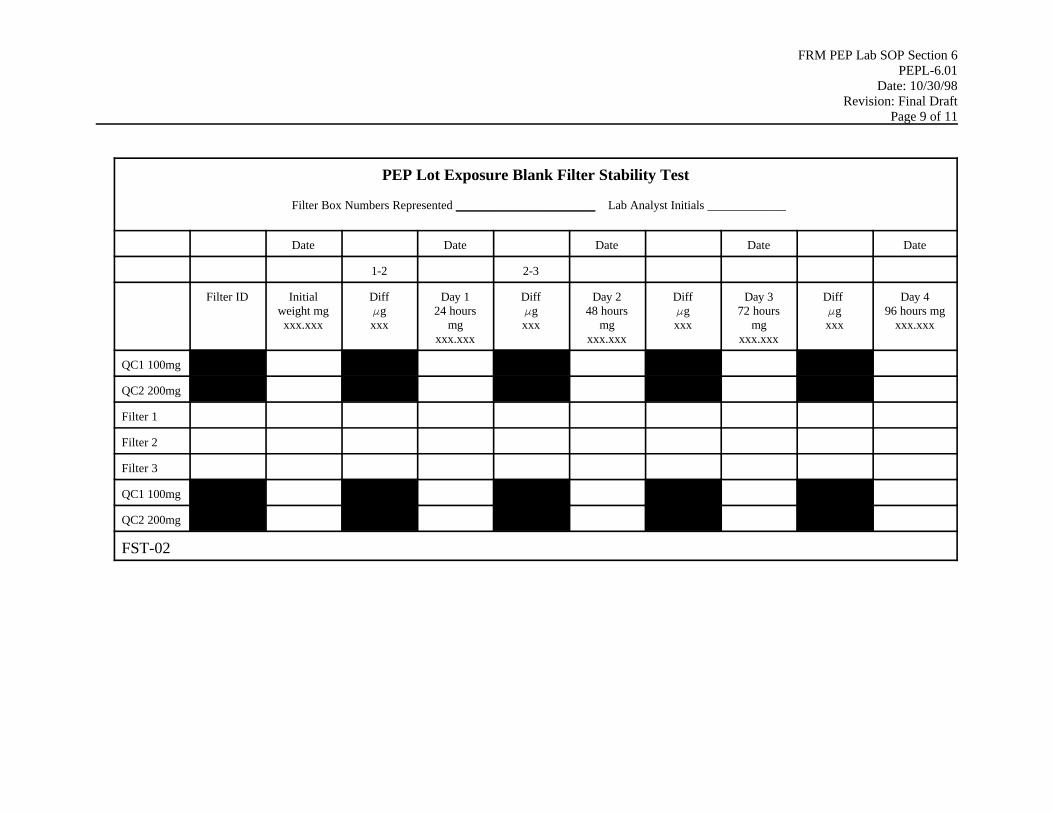
FRM PEP Lab SOP Section 6PEPL-6.01
Date: 10/30/98Revision: Final Draft
Page 9 of 11
PEP Lot Exposure Blank Filter Stability Test
Filter Box Numbers Represented _______________________ Lab Analyst Initials _____________
Date Date Date Date Date
1-2 2-3
Filter ID Initialweight mgxxx.xxx
DiffFgxxx
Day 124 hours
mgxxx.xxx
DiffFgxxx
Day 248 hours
mgxxx.xxx
DiffFgxxx
Day 372 hours
mgxxx.xxx
Diff Fgxxx
Day 496 hours mg
xxx.xxx
QC1 100mg
QC2 200mg
Filter 1
Filter 2
Filter 3
QC1 100mg
QC2 200mg
FST-02

FRM PEP Lab SOP Section 6PEPL-6.01
Date: 10/30/98Revision: Final Draft
Page 10 of 11
PEP Postsampling Routine Filter Stability Test
Filter Batch Number Represented _______________________ Lab Analyst Initials _____________
Date Date Date Date Date
1-2 2-3
Filter ID Day 124 hr
weight mgxxx.xxx
DiffFgxxx
Day 212-24 hours
mgxxx.xxx
DiffFgxxx
Day 312-24 hours
mgxxx.xxx
DiffFgxxx
Day 412-24 hours
mgxxx.xxx
Diff Fgxxx
Day 512-24 hours
mgxxx.xxx
QC1 100 mg
QC2 200 mg
Filter 1
Filter 2
Filter 3
QC1 100 mg
QC2 200 mg
FST-03

FRM PEP Lab SOP Section 6PEPL-6.01
Date: 10/30/98Revision: Final Draft
Page 11 of 11

FRM PEP Lab SOP Section 6PEPL-6.01
Date: 10/30/98Revision:Final Draft
Page 11 of 11
PEP Filter Weighing Data Entry Form
Batch Type: PRE POST Batch No.
Date _________ Analyst Initials _____________
Mean Temp for Past 24 hours: _______ SD:________Mean RH for Past 24 hours: _________ SD:________
Sample Filter ID Filter Type 00/ LB/FBCO/BD/PD
CassetteID
Weight 1xxx.xxx mg
Weight 2xxx.xxx mg
Flag
QC1 100 mg
QC2 200 mg
Filter
Filter
Filter
Filter
Filter
Filter
Filter
Filter
Filter
Filter
Filter
Filter
Filter
Filter
Filter
Duplicate 1 BD
Duplicate 2 DU
Duplicate 3 DU
QC1 100 mg
QC2 200 mg
BAT-01

FRM PEP Lab SOP Section 7PEPL-7.01
Date: 10/30/98Revision: Final Draft
Page 0 of 7
Weighing Laboratory Standard Operating Procedurefor the PM2.5 FRM Performance Evaluation Program
Section 7.0 Calibrations

FRM PEP Lab SOP Section 7PEPL-7.01
Date: 10/30/98Revision: Final Draft
Page 1 of 7
Weighing Laboratory Standard Operating Procedurefor the PM2.5 FRM Performance Evaluation Program
Operation: Quarterly Verification of Working Mass ReferenceStandards
SOP: PEPL-7.01
Name: Printed Signature Date
Mark Shanis
Contents (applicable to this SOP)
Section Page
1. Scope and Applicability 22. Summary of Method 23. Definitions 24. Interferences 25. Personnel Qualifications 36. Apparatus and Materials 37. Instrument Calibration Procedures 38. Troubleshooting 59. Data Acquisition, Calculation
and Reduction 5

FRM PEP Lab SOP Section 7PEPL-7.01
Date: 10/30/98Revision: Final Draft
Page 2 of 7
1.0 Scope and Applicability
This SOP will be used every 3 months to compare the working standards against the laboratoryprimary standards to ensure that the working standards are still within the acceptance criteria oftheir certified weight. This method is applicable to all weighings using a single-pan, fullyelectronic Sartorius Model MC5 microbalance that combines digital indications with the use of abuilt-in (internal) weight (5 g), and contains software for autozero, internal calibration, and autocorrection for air bouyancy and temperature sensitivity adjustment, if needed.
2.0 Summary of Method
The double-substitution procedure is one in which a standard (primary standard) and an unknownweight (working standard) are intercompared twice to determine the average difference betweenthe two weights. Errors in any built-in weights or in the balance indications are eliminated byusing the balance only as a comparator and by calibrating the balance indications over the range ofuse for the measurement. Accordingly, the procedure is especially useful for high-accuracycalibrations. The procedure is a version of SOP No.4 in NIST Handbook No.145 tailored to thisspecific application and equipment configuration.
The working and primary standard weights are each weighed twice. First, the working standard isweighed, and then the primary standard is weighed. Then the primary weighing is repeated; andfinally the working standard is weighed again. All weighings are made at regularly spaced timeintervals to average out any effects of instrument drift.
3.0 Definitions
The following symbols are used in this procedure: p = the PE lab “primary” standard weight. w = the working standard weight to be verified. M = the mass of a specific weight. Subscripts p, and w are used to identify the weight. AM = the apparent mass of a specific weight. Subscripts p, and w, are used to identify the
weight.
4.0 Interferences
Due to the weights of the standards being small, contamination of the weights and/ormicrobalance can affect the success of the calibration. It is recommended that, immediatelybefore performing this procedure, the laboratory analyst (LA) completely clean or cover bodyareas that might be sources of contamination

FRM PEP Lab SOP Section 7PEPL-7.01
Date: 10/30/98Revision: Final Draft
Page 3 of 7
The LA must wear a clean lab coat over potentially contaminated clothes and must weardisposable, non-contaminating, powderless antistatic gloves. No one who is coughing or sneezingshould be allowed in the weighing/conditioning room.
5.0 Personnel Qualifications
Certification by passing the written examination and the hands-on practical examination for thelaboratory component of PM2.5 FRM PE training.
6.0 Apparatus and Materials
ASTM Class 1 mass reference standards must be used for verifying the working standard weights.Mass standards must be available with calibration certificates traceable to NIST. The balance mustbe in good operating condition as verified by a valid control chart or preliminary experiments toascertain its performance quality. Keep the working standard weights in their box by the SartoriusModel MC5. Store the laboratory primary standard weights in an air-tight, air-resistant (or atleast fine particulate-excluding), limited access or locked compartment.
The following equipment is required to perform this procedure:
< Sartorious MC5 microbalance< ASTM Class 1 NIST-traceable working standard weight set (including 100 mg and 200
mg)< ASTM Class 1 NIST-traceable lab primary standard weights (100 and 200 mg)< mass forceps, non-metallic (one for each set)< a stop watch or other timing device to observe the time of each measurement< powder-free laboratory antistatic gloves< laboratory coat< Quarterly Standards Verification Form (Form QSV-01)< Alcohol swabs
7.0 Instrument Verification
7.1 Preliminary Procedure
1. Wipe down the work area with an alcohol swab.
2. Place the laboratory primary standard weights next to the working standard weights nearthe balance overnight to permit the weights and the balance to attain thermal equilibrium.
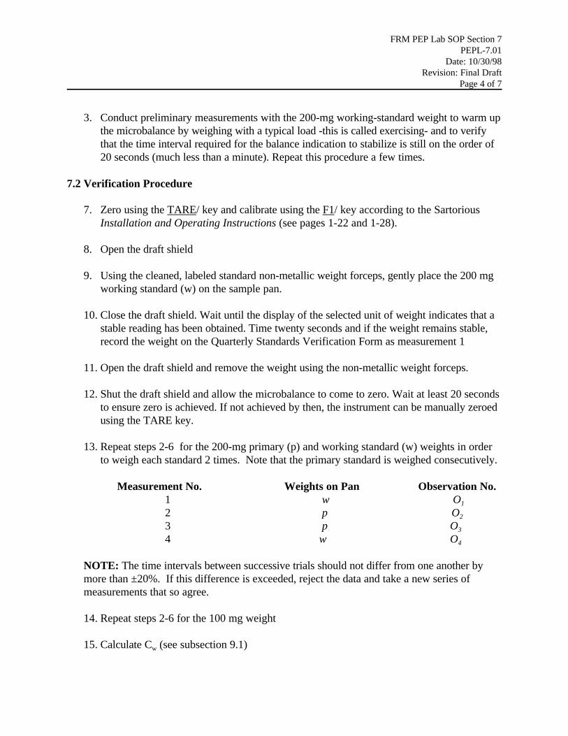
FRM PEP Lab SOP Section 7PEPL-7.01
Date: 10/30/98Revision: Final Draft
Page 4 of 7
3. Conduct preliminary measurements with the 200-mg working-standard weight to warm upthe microbalance by weighing with a typical load -this is called exercising- and to verifythat the time interval required for the balance indication to stabilize is still on the order of20 seconds (much less than a minute). Repeat this procedure a few times.
7.2 Verification Procedure
7. Zero using the TARE/ key and calibrate using the F1/ key according to the Sartorious Installation and Operating Instructions (see pages 1-22 and 1-28).
8. Open the draft shield
9. Using the cleaned, labeled standard non-metallic weight forceps, gently place the 200 mgworking standard (w) on the sample pan.
10. Close the draft shield. Wait until the display of the selected unit of weight indicates that a stable reading has been obtained. Time twenty seconds and if the weight remains stable,record the weight on the Quarterly Standards Verification Form as measurement 1
11. Open the draft shield and remove the weight using the non-metallic weight forceps.
12. Shut the draft shield and allow the microbalance to come to zero. Wait at least 20 secondsto ensure zero is achieved. If not achieved by then, the instrument can be manually zeroedusing the TARE key.
13. Repeat steps 2-6 for the 200-mg primary (p) and working standard (w) weights in orderto weigh each standard 2 times. Note that the primary standard is weighed consecutively.
Measurement No. Weights on Pan Observation No. 1 w O1
2 p O2
3 p O3
4 w O4
NOTE: The time intervals between successive trials should not differ from one another bymore than ±20%. If this difference is exceeded, reject the data and take a new series ofmeasurements that so agree.
14. Repeat steps 2-6 for the 100 mg weight
15. Calculate Cw (see subsection 9.1)

FRM PEP Lab SOP Section 7PEPL-7.01
Date: 10/30/98Revision: Final Draft
Page 5 of 7
16. Subsequent measurements of Cw must be with + 2 ug of the initial Cw value
8.0 Troubleshooting
If the test results do not indicate acceptable agreement (2 ug) and a repetition produces thesame results, use SOP PEPL 7.02 to confirm that the external primary standard (5g) and theModel MC5's internal standard (5g) still agree. If they do, arrange to have the primarystandard weight checked against an independent, certified weight of the same or greaterconfidence level of accuracy. If they don’t agree, the WAM should authorize consultationwith the service technician.
9.0 Data Acquisition, Validation, Calculations, and Data Reduction
9.1 Calculations
Calculate the apparent mass correction, Cw, for the test (working standard) weight (w) asfollows, according to the sequence used. In each case, the apparent mass corrections for theprimary standard weight, Cp , are included. The symbols Np and Nw refer to the nominal valuesof p and w, respectively.
Cw = Cp + ((O1- O2+ O4 - O3 )/2) + Np - Nw Equation 1
9.2 Assignment of Uncertainty (Optional)
The limits of uncertainty, U, include estimates of the mass standards used, Us , plus theuncertainty of the measurement, Um , at the 99.73% level of confidence. Um is estimated by
ts Equation 2
where s is the standard deviation of measurement and t is obtained from Table 9.3 ( seeattached).
Then U = ± [ Us + ts ] Equation 3
9.2.1 Precision of Measurement Known from Control Chart Performance (Optional) (See SOP No. 9 in NIST Handbook No. 145.)
The value for s is obtained from the control chart data. Statistical control will need to beverified by measuring at least one check standard when the above measurements are beingtaken.

FRM PEP Lab SOP Section 7PEPL-7.01
Date: 10/30/98Revision: Final Draft
Page 6 of 7
Use the value of t (corresponding to a probability level of 99.73%) from Table 9.3 (NISTReference) appropriate for the number of degrees of freedom (df), < , on which the controllimits of the control chart are based. For each measurement on a control chart, identify thenumber of measurements used to obtain that value (n) and subtract 1 (df = < = n-1).
9.2.2 Precision Estimated from Series of Measurements (Optional)
Measure a stable test object at least seven 7 times, no two measurements of which may be ona single day. Calculate the mean and the standard deviation in the conventional manner, whichis already provided in the text and equations of SOP PEPL 2.01, subsection 10.2. Theequations are the same as those in NIST Handbook No. 145, where they are used to calculatethe value of s that is used in section 4.4 of SOP No. 9 in Handbook No. 145. In this caseselect the value for t from table 9.3 based on the number of degrees of freedom involved incomputing s.
Note: Repetitive measurements made on the same day estimate only the short-term standarddeviation.

FRM PEP Lab SOP Section 7PEPL-7.01
Date: 10/30/98Revision: Final Draft
Page 7 of 7
Quarterly Standard Verification Form
Test No. : _______ Form(at) No. : _______ , Date :_______
Item Identification:____________________ Balance :________________
Standard Identification:________________Observer:_______________
cp (200 mg)= ______ ± _______ cp (100 mg)= ______ ± _______
Time :__________ Balance Standard Deviation : ____________
200 mg Test
Measurement Weights Observations No.
1 w O1 =
2 p O2 =
3 p O3 =
4 w O4 =
100 mg Test
Measurement Weights Observations No.
1 w O1 =
2 p O2 =
3 p O3 =
4 w O4 =
Form QSV-01

FRM PEP Lab SOP Section 7PEPL-7.02
Date: 10/30/98Revision: Final Draft
Page 1 of 4
Weighing Laboratory Standard Operating Procedurefor the PM2.5 FRM Performance Evaluation Program
Operation: External Calibration of AnalyticalMicrobalance
SOP: PEPL-7.02
Name: Printed Signature Date
Mark Shanis
Contents (applicable to this SOP)
Section Page
1. Scope and Applicability 22. Summary of Method 23. Definitions 24. Cautions 25. Personnel Qualifications 36. Apparatus and Materials 37. Procedure 38. Troubleshooting 4

FRM PEP Lab SOP Section 7PEPL-7.02
Date: 10/30/98Revision: Final Draft
Page 2 of 4
1.0 Scope and Applicability
This SOP describes an external calibration of a Sartorius Model MC5 microbalance. An externalcalibration should be performed ONLY when routine quality control (QC) checks (e.g.,microbalance verifications using working standards, replicate filter weighings) indicate thatthe microbalance may be out of calibration and is approved by the WAM.
2.0 Summary of Method
The microbalance's software is set so that weighing a 5-g primary mass reference standard withNIST traceability will produce a digital display of 5 g.
3.0 Definitions
Appendix A contains a glossary of the terms used in the PEP. For this SOP, "external calibration"is a one-point calibration of the microbalance using a mass reference standard.
4.0 Cautions
To ensure maximum stability, leave the microbalance turned on at all times. This procedure willenable the microbalance to be operational at any time and will eliminate the need for a warmupperiod before analyses can be performed.
Have the microbalance calibrated on a regular basis (e.g., twice yearly) by a microbalance servicetechnician and maintain it according to the manufacturer’s recommendations. The calibrationshould be traceable to NIST-traceable mass reference standards.
If the microbalance cannot be calibrated according to this SOP, have it adjusted and repaired byan authorized microbalance service technician according to the manufacturer’s directions. Donot attempt to adjust or repair the microbalance.
Use smooth, nonmetallic forceps for handling mass reference standards. Handle the standardsonly with these forceps and do not use the forceps for any other purpose. Mark the forceps todistinguish them from the forceps used to handle filters. Clean the forceps with alcohol and lint-free wipes and then allow them to air-dry before handling the standards. Handle the standardscarefully to avoid altering their masses by damage or contamination.
This procedure uses the primary standards, not the working standards.

FRM PEP Lab SOP Section 7PEPL-7.02
Date: 10/30/98Revision: Final Draft
Page 3 of 4
5.0 Personnel Qualifications
Certification by passing the written examination and the hands-on practical examination for thelaboratory component of PM2.5 FRM PE training is required.
6.0 Apparatus and Materials
The following equipment are required to perform this procedure:
< analytical microbalance< NIST-traceable, laboratory primary mass reference standard (ASTM Class 1)< mass non-metallic forceps for handling the standard< Powder-free laboratory antistatic gloves< laboratory coat
7.0 Procedure
7.1 Instrument or Method Calibration
1. Turn off the balance display using the ON/OFF key and then turn it back on. While allsegments are displayed, briefly press the PRINT key. The balance model should bedisplayed. Press the CF key to display the serial number. Record the balance model andserial number in the laboratory QC notebook. Press the CF key again to quit this function.
2. Unload the weighing pan and close the draft shield.
3. Press the TARE key for at least 2 seconds until "C.I." and "CAL" display.
4. Press the F2 key until "C.E." (for external calibration) displays.
5. Press the TARE key again. When a zero readout is displayed, press the F1 key. Thecalibration weight readout now will be in grams.
6. If external interference affects the calibration procedure, the error message "Err02" willappear briefly. In this case, repeat step 5.
7. Enter the certified mass of the mass reference standard using the numeric keys. Thenpress the F1 key identified on the weight display by "STO" to store this mass value. Enterthe date and time, the certified mass of the mass reference standard, and the standard'sidentification number in the laboratory QC notebook.

FRM PEP Lab SOP Section 7PEPL-7.02
Date: 10/30/98Revision: Final Draft
Page 4 of 4
8. Open the draft shield and transfer the standard to the center of the weighing pan using theforceps. Close the draft shield. The microbalance will generate an audible signal when ithas obtained a stable measurement of the standard's weight.
9. Open the draft shield and transfer the standard back to its protective container. Close thedraft shield.
8.0 Troubleshooting
Consult the Installation and Operating Instructions for the microbalance. The document’stroubleshooting guide is on pages 1-33 and 1-34. To assess affects of temperature on weighingsensitivity, use the calibration test on pages 1-37and 1-38. If the balance may have been moved,use the test on page 1-39.

FRM PEP Lab SOP Section 7PEPL-7.03
Date: 10/30/98Revision: Final Draft
Page 1 of 8
Weighing Laboratory Standard Operating Procedurefor the PM2.5 FRM Performance Evaluation Program
Operation: Quarterly Verification of RecordingThermometer and Recording Hygrometer
SOP: PEPL-7.03
Name: Printed Signature Date
Mark Shanis
Contents (applicable to this SOP)
Section Page
1. Scope and Applicability 22. Summary of Method 23. Verification Acceptance Criteria 34. Definitions 35. Cautions 36. Personnel Qualifications 47. Apparatus and Materials 48. Instrument Verification Procedure 49. Troubleshooting 5

FRM PEP Lab SOP Section 7PEPL-7.03
Date: 10/30/98Revision: Final Draft
Page 2 of 8
1.0 Scope and Applicability
The recording thermometer and the recording hygrometer of the environmental control system forthe PM2.5 conditioning and weighing room measure and display the temperature and RH inside thePM2.5 conditioning environment on a continuous basis. These instruments' responses are recordedcontinuously by a computer-based data acquisition system. The accuracy of the responses isverified by comparison testing at least one % RH value -the set point, usually 35% RH- on aquarterly basis using a laboratory reference standard, the instant model of the Fisherbrand™Certified Traceable Digital Hygrometer/Thermometer (DH/T).
2.0 Summary of Method
The laboratory reference, instant model Fisherbrand™ Certified Traceable DigitalHygrometer/Thermometer (DH/T), is placed inside the conditioning environment, which isallowed to vary, during a 24 hour period, up to a±2 EC control limit within an allowed 20 to 23ECoperating range and up to ±5% RH control limit within an allowed 30 to 40% RH operatingrange. The responses of the reference instrument’s combination probe are then compared withthe responses of the conditioning environment control system’s recording thermometer andrecording hygrometer. Mean and standard deviation are calculated from the recorded responses.The mean is compared to the operating range and must be within it. The standard deviations areconverted to the appropriate T or RH units and compared to the control limits and must be withinthem.
The laboratory reference DH/T is a combination probe containing two sensors. One sensor is athermistor that is calibrated by the manufacturer against a NIST traceable temperature so that itmeasures the ambient or [”dry-bulb”] temperature in the weighing and conditioning room. Thedigital hygrometer component of the probe is a precision, thin-film (semipermeable membrane)capacitance sensor. The circuitry of the combination probe uses the precalibrated thermistoroutput and the calibrated capacitance change resulting from the amount of moisture allowed intothe sensor by the semipermeable membrane to calculate the RH. The digital thermometer and RHprobe components measure and the LCD and computer readouts display the selected high, low orcurrent values.
This procedure also verifies that the conditioning environment‘s temperature and humidity controlsystems are operating within their control limits.

FRM PEP Lab SOP Section 7PEPL-7.03
Date: 10/30/98Revision: Final Draft
Page 3 of 8
3. 0 Verification Acceptance Criteria
Table 8-2 of the Implementation Plan (8/98) for the PM2.5 FRM PEP presents the followingacceptance criteria for laboratory QC checks:
Temperature calibration ±2ECHumidity calibration ±2% RH
The certified accuracies of the Fisher brand ™ instant model of the DH/T are ± 0.2EC and ± 1.5% RH which, in this application, means that the Fisherbrand instant model of the DH/T meets thegeneral standard verification requirement that a verification standard must be as accurate or moreaccurate than the acceptance criteria it is being used to verify. The certification of theseaccuracies are important. Therefore the certificate that comes with the DH/T to provides thisquality assurance should be checked when it arrives by confirming with NIST that any referenceto NIST testing is correct.
4.0 Definitions
Appendix A contains a glossary of the terms used in the PEP.
For this SOP, calibration is distinguished from verification as follows: Calibration involves amulti-point characterization of a sensor's response and adjustment, if necessary, to bring its outputinto agreement with a NIST-traceable standard throughout the calibration range. Verificationtypically involves a single or multipoint check of a sensor's response to verify that it is functioningwithin a tolerance range.
5.0 Cautions
RH values inside the conditioning environment will change as the temperature varies, as shown inthe Background Information subsection located at the end of this section. Within the operatingrange of the conditioning environment, a 1EC change in the temperature will produce anapproximately 5% RH change. Remain aware of this interaction of verification parameters astemperature and humidity levels inside the conditioning environment are varied.
The LA should be sure to utilize the arrangement to have the certified calibration of the laboratoryreference DH/T verified annually using NIST-traceable temperature and/or humidity referencestandards by the manufacturer or at a State weights and measures laboratory holding a NISTCertificate of Traceability or at a calibration laboratory that is accredited by the NationalVoluntary Laboratory Accreditation Program (NVLAP).
The humidity sensor, a precision thin film (semipermeable membrane) capacitance-based sensor,and the temperature sensor, a thermistor, are extremely unlikely to be operated, even accidentally,

FRM PEP Lab SOP Section 7PEPL-7.03
Date: 10/30/98Revision: Final Draft
Page 4 of 8
outside of their very wide operating range. However since the combination probe and LCDreadout are powered by a 9V alkaline battery with a 1 year intermittent and 100 hour continuoususe limitation, attention should be given to the low battery indicator as the use time of the systemapproaches the specified use limits. Since the system is based on electronic circuitry, check foreffects of any damage to the protective outer housings of the probe, cable, or LCD readoutcomponents.
6.0 Personnel Qualifications
Certification of passing the written examination and the hands-on practical examination for thelaboratory component of PM2.5 FRM PE training is required.
7.0 Apparatus and Materials
The following equipment is required to perform this procedure:
< laboratory reference Fisherbrand™ instant model DH/T< humidifiers and/or dehumidifiers, if the conditioning environment does not have a
humidification capability< provision for manual or computer data recording.
8.0 Instrument Verification Procedure
NOTE: Be sure to read the environmental control system and DH/T manufacturer’s operationinstructions before starting this procedure.
1. Install the laboratory reference DH/T in the conditioning environment. Locate thecombination probe as close as possible to the temperature and RH sensing components ofthe environmental control system of the Laboratory’s conditioning and weighing area. Inconsidering sensor placement based on the air flow patterns in the controlled area, placethe reference standard probe downstream of the control system’s sensors and upstream ofthe microbalance, so that the air entering the controlled area goes first by the referenceprobe and then, without obstruction, by the balance.
2. Turn on the DH/T by pressing the ON key on the face of the LCD /control component of the system and allow this instrument to stabilize. When the unit is initially turned on, it willbe in the Auto Scroll mode. It will display a reading, pause, and then scroll to the nextmeasurement. Press the Hold part of the Hold /Scroll key to stop the scrolling. The displaywill only read the present measurement.
3. When the recording thermometer and recording hygrometer readings indicate that the temperature and RH have stabilized, record, manually or by computer, the readings of the

FRM PEP Lab SOP Section 7PEPL-7.03
Date: 10/30/98Revision: Final Draft
Page 5 of 8
recording thermometer, the recording hygrometer, and the DH/T’s T and RH probe (onthe LCD readout screen or receiving monitor of the DH/T computer output. Record inthe laboratory QC notebook (paper or electronic form), in data format shown in Figure7.03-1 below.
4. Calculate the difference between the recording thermometer measurement and thereference instrument measurement for the conditioning environment setting and comparethis difference to the temperature verification acceptance criterion of ±2EC.
5. Calculate the difference between the recording hygrometer measurement and the laboratory reference DH/T measurement for the conditioning environment settings and compare this difference to the T and RH verification acceptance criterion of ±2% RH.
Figure 7.03-1: T, RH 1-pt Monthly Verification Data Form
Date_________ LA or Svc. Technician_________________ T-STD Model No.________
T-STD Ser. No.____________ RH STD Model No. _________ RH-STD Ser.No.__________
Recording T/RH Model No.___________, Ser.No._______________Record of Test Observations( 5 min. Avg., at least 1 hr.):
Mean Recording T (EEC) =_____, S.D. =______ ; Mean Std. T (EEC) =_______, S.D.=_______ Mean Diff. (EEC)=_________
Mean Recording %RH =_______, S.D.=______ ; Mean Std % RH =_______, S.D.=_______Mean % Diff =__________
The T and RH may vary outside of the allowed mean ranges of 20 to 23 EC temperature or 30 to40 % RH or the 24 hour allowed variability ranges of ±2EC or ±2% RH during the year forperiods longer than 5-10 minutes during changes, such as door openings, multiple person entry orpresence, etc. This may occur more commonly in some geographical and seasonal situation s thanothers, such as high heat and humidity in Athens, GA in August. If this occurs, allow the DH/T tomeasure, and the LA should record the high, low, and current values, so that mean and standarddeviation for more than one point can be computed and compared as above to the output of theenvironmental control system’s output for the same period. 9.0 Troubleshooting
1. If the measurements of the recording thermometer and the reference instrument disagreeby more than the temperature verification acceptance criterion at the conditioningenvironment setting or if stable readings cannot be obtained, reverify the recording

FRM PEP Lab SOP Section 7PEPL-7.03
Date: 10/30/98Revision: Final Draft
Page 6 of 8
thermometer measurement. If the two readings still disagree, investigate the recordingthermometer and the reference instrument and take appropriate corrective action. Thiscorrective action may include the having the LA ask the WAM to authorize previouslyarranged facility or external service technician support in (1) adjusting the calibration ofthe recording thermometer to agree with the reference instrument, (2) repairing therecording thermometer, and/or (3) recertifying the recording thermometer and referenceinstrument against a NIST-traceable temperature standard at a State weights andmeasures laboratory holding a NIST Certificate of Traceability or at a calibrationlaboratory accredited by NVLAP.
If the recording thermometer cannot be calibrated, make note of this problem in thelaboratory QC notebook. Attach a copy of the service technician’s report.
2. If the measurements of the recording hygrometer and the laboratory reference DH/Thygrometer disagree by more than the RH verification acceptance criterion at theconditioning environment setting or if stable readings cannot be obtained, reverify thehygrometer measurement. If the two readings still disagree, investigate the hygrometerand the laboratory reference psychrometer and take appropriate corrective action. Thiscorrective action may include having the LA ask the WAM to authorize previouslyarranged facility or external service technician support in (1) adjusting the calibration ofthe recording hygrometer to agree with the laboratory reference psychrometer, (2)repairing the hygrometer, and/or (3) recertifying the laboratory reference psychrometerusing NIST-traceable temperature or humidity reference standards at a State weights andmeasures laboratory holding a NIST Certificate of Traceability or at a calibrationlaboratory accredited by NVLAP.
If the recording hygrometer cannot be calibrated, make note of this problem in thelaboratory QC notebook. Attach a copy of the service technician’s report.
3. If the conditioning environment cannot maintain the temperature and RH at the specifiedsetting, troubleshoot the control systems in the conditioning environment and takeappropriate corrective action. This corrective action may include having the conditioningenvironment repaired by an authorized service representative from the company thatmanufactured the conditioning environment system. If the conditioning environmentcannot be controlled , make note of this problem in the laboratory QC notebook.
Background Information
If questions arise regarding the T or RH readings of electronically-based sensors, NISTrecommends comparison for T to a recently certified, NIST-traceable ( or recertified, NISTtraceable) dry bulb thermometer; or for RH to a series of salt solutions ( according to ASTMstandard procedure E104. The LA is not expected to perform such tests.

FRM PEP Lab SOP Section 7PEPL-7.03
Date: 10/30/98Revision: Final Draft
Page 7 of 8
Service agreements and annual recertification agreements have been arranged by the WAM incase problems or questions arise that suggest the need for such tests. This information and theinformation provided below are just included here as background knowledge.
The relationship between the dry-bulb temperature, the wet-bulb temperature, and the RH in theconditioning environment's operating range is given in the following table. Dry-bulb temperaturesappear across the top of the table, wet-bulb temperatures appear down the left side of the table,and RH values appear in the interior cells.
Wet-BulbTemperature (EC)
Dry-Bulb Temperature (EC)
20.0 20.5 21.0 21.5 22.0 22.5 23.0
10.7 29.2 26.9 24.8 22.8 20.9 19.1 17
11.2 32.4 30.1 27.9 25.7 23.7 21.8 20.0
11.7 35.7 33.3 31.0 28.8 26.7 24.7 22.8
12.2 39.1 36.5 34.1 31.8 29.6 27.6 25.6
12.7 42.5 39.8 37.3 34.9 32.7 30.5 28.4
13.2 46.0 43.2 40.6 38.1 35.7 33.5 31.3
13.7 49.5 46.7 43.9 41.3 38.9 36.5 34.3
14.2 53.1 50.1 47.3 44.6 42.0 39.6 37.3
14.7 56.8 53.7 50.8 48.0 45.3 42.7 40.3
If you know the dry-bulb temperature (Tdb) and the wet-bulb temperature (Twb), and want toobtain the RH (in percent), use these formulas as follows:
RH = 100 [Dws(Twb)/Dws(Tdb)] (7-4)
Dws(Twb) = exp[(C1/Twb) + C2 + C3Twb + C4Twb2 + C5Twb
3 + C6ln(Twb)] (7-5)= water saturation vapor pressure (in psia) at the wet-bulb absolute temperature (inKelvin, E R = E F + 459.67)
Dws(Tdb) = exp[(C1/Tdb) + C2 + C3Tdb + C4Tdb2 + C5Tdb
3 + C6ln (Tdb)] (7-6)= water saturation vapor pressure (in psia) at the dry-bulb absolute temperature (inKelvin, E R = E F + 459.67)
where C1 = -1.0440397 x 10+4,C2 = -1.1294650 x 10+1,

FRM PEP Lab SOP Section 7PEPL-7.03
Date: 10/30/98Revision: Final Draft
Page 8 of 8
C3 = -2.7022355 x 10⁻²,C4 = +1.2890360 x 10⁻⁵,C5 = -2.4780681 x 10⁻⁹ , andC6 = +6.5459673 x 10+0.
Woods Hole Oceanographic Institution has measured RH at the sea surface on buoys using thin-film polymer, capacitative sensors. Between 1990 and 1994, 14 sensors were calibrated on aregular basis using an RH chamber with a calibration accuracy of approximately 0.3% RH at 40%RH. During an approximately 600-day period since their calibration, the sensors' responses wereverified at nominal RHs ranging from 20 to 90% RH at 10% RH intervals. During this period, 35independent verifications were obtained at 40% RH. The sensors had random shifts in theircalibrations of ±2 to 3% RH at 40% RH. There did not appear to be any long-term drifts.

FRM PEP Lab SOP Section 8PEPL-8.01
Date: 10/30/98Revision: Final Draft
Page 0 of 15
Weighing Laboratory Standard Operating Procedurefor the PM2.5 FRM Performance Evaluation Program
Section 8.0 Filter Weighing

FRM PEP Lab SOP Section 8PEPL-8.01
Date: 10/30/98Revision: Final Draft
Page 1 of 15
Weighing Laboratory Standard Operating Procedurefor the PM2.5 FRM Performance Evaluation Program
Operation: Filter Weighing
SOP: PEPL-8.01
Name: Printed Signature Date
Mark Shanis
Contents (applicable to this SOP)
Section Page
1. Scope and Applicability 22. Summary of Method 23. Definitions 24. Cautions 25. Interferences 36. Personnel Qualifications 47. Apparatus and Materials 48. Procedures 59. Troubleshooting 13

FRM PEP Lab SOP Section 8PEPL-8.01
Date: 10/30/98Revision: Final Draft
Page 2 of 15
1.0 Scope and Applicability
This SOP applies to the presampling and postsampling weighing of filters used in the PM2.5 PEP.It also provides information for preparing the filters for shipment to the field.
2.0 Summary of Method
Filters are conditioned and once they have reached equilibrium are batched (PEPL-6.01) and weighed either to record a presampling weight or a postsampling weight. Various types of QCsamples are also weighed and reviewed in order to accept the data from the weighing session.
3.0 Definitions
Appendix A contains a glossary of the terms used in the PEP.
4.0 Cautions
< filters should be weighed as soon as there are enough samples received to make a batchbut must be weighed within 10 days of sample receipt
< keep the microbalance in the same controlled-environment room that will be used tocondition the filters
< ensure the laboratory has a HEPA-filtered air supply system on its inlet air system tominimize airborne contaminants
< change the filter monthly< maintain the room at a slightly positive pressure so that the air flows away from the
balance and conditioning area < minimize ingress to and egress from the room< minimize dust contamination by cleaning the weighing area daily; by installing, using, and
as needed, replacing sticky floor coverings (minimum weekly) at the entrance to the room;and by wearing clean laboratory clothing over any clothing exposed to uncontrolledenvironments
< place the microbalance on a balance table to reduce vibrations< avoid bumping the microbalance to prevent disturbing its calibration< verify that the analytical microbalance has been calibrated by an authorized microbalance
service representative within the past 6 months< if more than one microbalance is used, make the pre- and postsampling measurements of
each filter on the same microbalance< verify that the working standards have been either recertified within the past year against
NIST-traceable mass standards at a State weights and measures laboratory holding aNIST Certificate of Traceability or at a calibration laboratory accredited by NVLAP andverified within the past 3 months against the laboratory primary standards at the weighinglaboratory according to SOP PEPL-7.01

FRM PEP Lab SOP Section 8PEPL-8.01
Date: 10/30/98Revision: Final Draft
Page 3 of 15
< check the working standards’ masses, after any incident of rough handling, and compareto their verified value.
< select working standards so that they will bracket the mass of a blank or loaded filter (thatis, 100 and 200 mg)
< when weighing filters, hold the filter (with filter forceps) only by the outer polyolefinsupporting ring, not by the filter material
< if the forceps ever touch the filter material of an exposed filter, flag the sample with thecode “LAC” on PEP Filter Data Entry Form BAT-01 and clean the forceps with disposable laboratory wipes to avoid cross-contamination
5.0 Interferences
Temperature effects the performance of the microbalance. Relative humidity effects moisturecontent and therefore the weight of the filter.
An important limitation of the method involves changes in the weight of a collected sample due tomishandling, chemical reactions, and volatilization. Handling procedures, choice of filter media,humidity and temperature control of the filter and sample during weighing, and promptness inweighing the sample following collection, all help control filter artifacts.
The chemical makeup of the PM2.5 particulate matter varies with the sampling location andsource. Thus, the magnitude of PM2.5 weight changes due to chemical and physical processes willalso vary with site location.
Minimize weight loss due to mechanical removal of particles from the filter by removing the filterfrom its cassette carefully, by conditioning the filter, and by neutralizing the electrostatic chargebuildup on the filter before weighing.
Filters may become contaminated during conditioning or weighing from particulate matter in theair or from dust on the microbalance or working surfaces. Reduce airborne contamination bypassing the air inside the conditioning environment through a HEPA filter. Reduce surfacecontamination by cleaning work surfaces with low-lint, disposable laboratory wipes beforeweighing the filters.
Stable readings of weights are a requirement. Consult the microbalance's operating manual formore information about obtaining stable readings.
5.1 Electrostatic Charge Neutralization
Errors in the gravimetric analysis of samples can also result from the buildup of an electrostaticcharge on the microbalance or on filters during their manufacture or during sampling (Engelbrechtet al. 1980). This electrostatic charge buildup will interfere with the microbalance weighing. Reduce the electrostatic charge on the microbalance by electrically grounding the microbalance

FRM PEP Lab SOP Section 8PEPL-8.01
Date: 10/30/98Revision: Final Draft
Page 4 of 15
and coating the nonconductive surfaces with an antistatic solution. Reduce the electrostaticcharge on filters using polonium-210 (210Po) antistatic strips immediately before the weighingprocess begins.
Common symptoms of a problem with electrostatic charge include noisy readout, drift, andsudden readout shifts. To reduce static charge on individual filters and within the microbalance,place a radioactive antistatic strip containing a very small amount (i.e., 500 picocuries) of 210Po inthe weighing chamber. 210Po antistatic strips neutralize electrostatic charges on items broughtwithin an inch of them. These antistatic strips are safe, commonly available, and inexpensive. 210Po has a half-life of 238 days. Change the antistatic strips every 6 months and discard the oldstrips according to the manufacturer’s recommendations and State and local regulations, ifapplicable.
Use antistatic solutions for coating (and, at appropriate and relatively infrequent intervals,recoating) the interior and exterior nonmetallic surfaces of the weighing chamber. This coatingfacilitates the draining of electrostatic charges away from these surfaces (by making themconductive) to a common ground to which the metallic conductive surfaces are connected. Placeearth-grounded conductive mats on the balance table surface and beneath the analyst’s shoesurfaces to reduce electrostatic charge buildup.
Even though a filter weight might stabilize within 30 to 60 seconds and no weight drift isobserved during that period, the microbalance may still be influenced by some electrostaticbuildup. It may still be necessary to repeat the neutralization procedure. Charge neutralizationtimes may need to be longer than 60 seconds for sampling situations when either a high amount ofcharge has developed on collected particles due to their origin or the particle loading on a filter islarge. Electrostatic charge buildup increases as the air becomes drier. A 60-second chargeneutralization may be sufficient in ambient indoor air conditioned to 37% RH and 23E C but notin 20% RH and 23 EC in arid environments. The latter environment may require that the filter sitfor more time near the antistatic strip.
6.0 Personnel Qualifications
Certification by having passed the written examination and the hands-on practical examination forthe laboratory component of the PM2.5 FRM PE training are required.
7.0 Apparatus and Materials
The following equipment is required to perform this procedure:
< Filter Weighing Form BAT-01< Filter Inventory and Tracking Form COC-01< filters< microbalance

FRM PEP Lab SOP Section 8PEPL-8.01
Date: 10/30/98Revision: Final Draft
Page 5 of 15
< high purity ethanol< QC mass working standards< working standard forceps< filter forceps< filter cassettes< metal filter caps< plastic shipping bags< sample labels< premoistened wipes or lint-free cloths and a small bottle of ethanol< polonium strips< powder free antistatic gloves< laboratory coats
8.0 Procedures
8.1 Prerequisites
8.1.1 Filter Weighing Readiness
Follow the presampling filter handling procedures in SOP PEPL-5.01 and the presampling filterconditioning procedures in SOP PEPL-6.01.
7. Measure the conditioning environment's temperature and RH on a continuous basis duringpresampling filter conditioning using electronic instruments whose outputs are recorded bya data acquisition system connected to a computer.
8. Calculate the means and ranges of the temperature and RH over the preceding 24-hourperiod.
9. Verify that the mean temperature in the conditioning environment has remained within theacceptance criteria (see Table 12-1) and that the temperature during the weighing sessionis controlled to within ±2 EC.
10. Verify that the mean RH has remained within the acceptance criteria (see Table 12-1) andthat the RH during the weighing session is controlled to within ±5%. Record these valuesin the LIMS and/or in the laboratory QC notebook. If the conditioning environment hasnot remained within these specifications, the filters cannot be weighed. Take appropriatetroubleshooting and corrective actions in that event.
11. If necessary, clean the microbalance’s weighing chamber and the surrounding area with afine, antistatic brush.
12. Clean the surfaces near the microbalance with disposable laboratory wipes

FRM PEP Lab SOP Section 8PEPL-8.01
Date: 10/30/98Revision: Final Draft
Page 6 of 15
13. Clean the forceps for handling mass reference standards and the filter forceps with anethanol-dampened, lint-free cloth or with the premoistened wipes. Allow the forceps toair-dry after cleaning. Make sure that the forceps are thoroughly dry before use becauseeven a small amount of moisture can cause a significant measurement bias.
14. Leave the microbalance plugged in and the power turned on at all times. This procedureenables the microbalance to be operational at any time and eliminates the need for apreliminary warmup period before analyses can be performed. The LCD screen does notneed to be on
15. Have all equipment clean and ready to prepare filter cassettes: caps, cassettes, stainlesssteel screens, 3 x 5" antistatic self-sealing bags, Form BAT-01, and indelible in markers orlabels. .
8.1.2 Microbalance-Turning off Default Auto Zero
The Sartorius@ Model MC5's autozero function should be turned off. The factory preset defaultfor this choice is always to have the autozero turned on. Ideally, the Sartorius service technicianmakes this adjustment when setting up the balance. If this has not been done, follow theprocedure on pages 2-2 and 2-6 of the Sartorius Installation and Operating Instructions. Theappropriate steps follow to change the autozero menu code setting:
Access the Menu:
7. Turn the balance off; turn it back on again
8. While all the segments are displayed (note a lot of 8s), briefly press the Tare/ key.
9. If -L- is displayed, unlock the menu as follows:-Remove the protective cap located on the left-hand side of the balance’s electronic computing device’s rear panel to expose the menu access switch.-Move the switch in the direction of the arrow (toward the right).
Set the code:
7. Press the F1/ key to change the left-hand number to 1.
8. Press the key with the underlined zero with the dot in the center to move to the middlenumber
9. Press the F1/ key to change the middle number to 6.

FRM PEP Lab SOP Section 8PEPL-8.01
Date: 10/30/98Revision: Final Draft
Page 7 of 15
10. Press the key with the underlined zero with the dot to move to the right-hand number(When you move to the right-hand number, the previously set numeric code will beindicated- that is, the auotozero code, 161).
11. Press the F1/ key once to change the right-hand number of the code to 2.
Confirm the code setting:
You must press the TARE/ key in order to confirm the code you have just set. This is indicated bythe “o" after the code.
1. Press the CF/ key to store the new menu setting.
8.2 Presampling Filter Weighing Procedure
This procedure describes the method for presample weighing of a box of filters (~50 filters) thathave been properly conditioned. Steps 1- 8 helps warm up the balance with a load, calledexercising the balance.
1. Open and close the microbalance draft shield (circular arrow key) two times to equilibratethe air in the draft shield chamber with room air.
2. Zero (using the TARE key) and internally calibrate (using the F1 key) the microbalanceaccording to the microbalance's operating manual. This may take 1-2 minutes.
3. Open the microbalance's draft shield.
4. Using working standard forceps, gently place the 100-mg working mass referencestandard on the sample pan. Close the microbalance's draft shield.
5. Wait until the microbalance’s display of the selected unit (mg) of weight indicates that astable reading has been obtained.
6. After a stable reading is indicated, time 20 seconds and if the weight remains stable,record the measured value of the standard in the LIMS and/or on the Filter WeighingData Entry Form BAT-01 and go to step 8
7. If the weight fluctuates within this 20 seconds, time another 20 seconds and record thereading. If after three attempts the microbalance does not provide a steady reading, takethe weight off and repeat steps 2-5.
8. Repeat steps 3-7 with the 200-mg working standard weight.

FRM PEP Lab SOP Section 8PEPL-8.01
Date: 10/30/98Revision: Final Draft
Page 8 of 15
9. If the verified and measured values of either working standard disagree by more than ±3µg, repeat steps 1-8. If the weights are acceptable, move to step 11.
10. If the two values still disagree, halt routine weighing and troubleshoot the entiremeasurement system and take appropriate corrective action. Corrective action mayinclude:
- conducting the calibration sensitivity test (Sartorius Installation and Operating Instructions, page 1-39),- calibrating the microbalance using the microbalances internal standard- recertifying the working standards against the laboratory primary standards, and/or asking the WAM to have a service technician adjust or repair the microbalance (PEPL-
7.01)- checking temperature and relative humidity with independent standards- calibrating the microbalance using an external laboratory primary standard (PEPL-7.02)
11. Shut the draft shield and allow the microbalance to come to zero. Wait at least 20seconds to ensure zero is achieved. If not achieved by then, the instrument can bemanually zeroed by using the TARE key.
12. Select the next routine filter for weighing and record the filter ID located on the outerpolyolefin support ring onto Form BAT-01. Indicate the filter type as either “00" for afield filter or “LB” for a laboratory blank
13. Take the filter from its Petrislide by gently pushing down (with the filter-handling forcepson the outer polyolefin support ring) one side of the filter. This should raise the other endof the filter and with a slight nudge, rest the filters edge on the Petrislide. You can thenaccess the outer polyolefin support ring with the filter-handling forceps.
14. Lay each filter, with its support ring side kept upward, on the 210Po antistatic strip for 30to 60 seconds immediately prior to weighing. Depending on the number of 210Po antistaticstrips available, procedures 12-14 can occur with a number of filters.
15. Open the microbalance draft shield.
16. Immediately transfer the filter to the center of the microbalance’s weighing pan and thenclose the draft shield. Center the filter on the weighing pan.
17. After the microbalance’s display of the selected unit of weight indicates a stable reading, time 20 seconds (as in steps 6 and 7 above) and record this value in the “Weight 1"column on Form BAT-01. If this process takes much longer than 20-30 seconds, evaluateconditions of the weighing room to identify a possible reason

FRM PEP Lab SOP Section 8PEPL-8.01
Date: 10/30/98Revision: Final Draft
Page 9 of 15
18. Remove the filter and put it back into the Petrislide and set it aside.
19. Take another filter and repeat steps 12-18.
20. After weighing 15 routine filters, or the end of the session, reweigh the first (routine)filter on every Form BAT-01 as a duplicate filter.
21. If the duplicate filter measurement is within ±15 µg of the original weight, go to step 24.
22. If the duplicate filter measurement disagrees from the original measurement by more than±15 µg, flag the filter “FLD” in the duplicate area. Set it back into the Petrislide andclose it. Mark the Petrislide “FLD” and set it aside from the other routine samples.
23. Reweigh the second and third filters on Form BAT-01. If either of these measurementsalso disagree by >±15 µg, place all samples back into the conditioning environment for aminimum of 12 hours and repeat the weighing procedure. Troubleshoot the entiremeasurement system and take appropriate corrective action.
24. At the end of the 15 routine weighings, reweigh both working standards by repeatingsteps 3-5. Compare the verified and measured values of the working standards; theyshould not disagree by more than + 3 ug. If unacceptable, repeat steps 1-8. Record themeasurements in the LIMS and/or on Form BAT-01. File the Form BAT-01 underSAMP/223.
25. Before weighing another 15 routine filters, follow the procedures in Section 8.2.2.
26. After completing the procedure in Section 8.2.2, repeat steps 3-25 if more filter are to beprepared.
NOTE: Petrislides with these filters should not be placed on the same tray that holds filtersbeing conditioned from the field.
8.2.1 Laboratory Blanks
Weigh enough laboratory blanks (5 per filter box of 50 filters) during a presampling weighingsession to provide at least one single-use laboratory blank during each subsequent postsamplingweighing session. Label the laboratory blank “LB” for filter type.
1. Follow steps 12-19 above.
2. Place the laboratory blank back in the Petrislide.
3. Label the Petrislide with the filter ID and the filter type.

FRM PEP Lab SOP Section 8PEPL-8.01
Date: 10/30/98Revision: Final Draft
Page 10 of 15
4. Place the laboratory blank back into the filter conditioning environment. Leave it 3/4covered similar to a normal sample.
8.2.2 Filter Field Preparation
This procedure describes the process for placing the filters that have just been weighed into theircassettes, metal filter caps, and plastic shipping bags for shipment to EPA Regions.
NOTE: The filter IDs on the filter support ringare very small, which makes them prone toentry errors. These filters should be placed inthe same order that they are listed on BAT-01in order to avoid data entries. However, beforeplacing the filter into a cassette, reverify thefilter numbers.
Figure 8.1 illustrates the filter cassetteassembly necessary for shipment 1. Select a weighed filter and take a clean
filter cassette.
2. Identify the correct filter ID on FormBAT-01.
3. Record the cassette ID onto Form BAT-01; place the filter into the cassette.
4. Record the same cassette ID on a plasticantistatic self sealing shipping bag (labelor indelible marker).
5. Place the protective metal filter caps onthe cassette, and place the cassette intothe antistatic self sealing plastic shippingbag and seal the bag.
6. Select another routine filter and repeatsteps 1-5.
7. Add this cassette value and presampling weighing date to a Filter Inventory and TrackingForm COC-01.
Figure 8.1 Filter cassette equipment and filter cassette inantistatic sample bag.

FRM PEP Lab SOP Section 8PEPL-8.01
Date: 10/30/98Revision: Final Draft
Page 11 of 15
8.2 Postsampling Filter Weighing
This procedure describes the method for postweighing filters that have been batched according toSOP PEPL-6.01( section 8.3.1).
1. Follow the postsampling filter handling procedures in SOP PEPL-5.01 and thepostsampling filter conditioning procedures in SOP PEPL-6.01( section 8.3.2).
2. Select the appropriate Filter Data Entry Form BAT-01
3. Place the filters to be weighed in the order they are listed on Form BAT-01.
4. Open and close the microbalance draft shield (circular arrow key) two times to equilibratethe air in the draft shield chamber with the room air.
5. Zero (using the TARE key) and internally calibrate (using the F1 key) the microbalanceaccording to the microbalance's operating manual. This may take 1-2 minutes.
6. Open the microbalance's draft shield.
7. Using working standard forceps, gently place the 100-mg working mass referencestandard on the sample pan. Close the microbalance's draft shield.
8. Wait until the microbalance’s display of the selected unit (mg) of weight indicates that astable reading has been obtained.
9. After a stable reading is indicated, time 20 seconds and if the weight remains stable, record the measured value of the standard in the LIMS and/or on Filter Weighing DataEntry Form BAT-01. and go to step 8
10. If the weight fluctuates within this 20 seconds, time another 20 seconds and record thereading. If after three attempts the microbalance does not provide a steady reading, takethe weight off and repeat steps 2-5.
11. Repeat steps 6-10 with the 200-mg working standard weight.
12. If the verified and measured values of either working standard disagree by more than ±3µg, repeat steps 3-11. If the weights are acceptable, move to step 14.
13. If the two values still disagree, halt routine weighing and troubleshoot the entiremeasurement system and take appropriate corrective action. Corrective action mayinclude:
- conducting the calibration sensitivity test (Sartorius Installation and Operating

FRM PEP Lab SOP Section 8PEPL-8.01
Date: 10/30/98Revision: Final Draft
Page 12 of 15
Instructions, page 1-39),- calibrating the microbalance using the microbalances internal standard- recertifying the working standards against the laboratory primary standards, and/or asking the WAM to have a service technician adjust or repair the microbalance (PEPL-7.01)- checking temperature and relative humidity with independent standards- calibrating the microbalance using an external laboratory primary standard (PEPL-7.02)
14. Shut the draft shield and allow the microbalance to come to zero. Wait at least 20 seconds toensure zero is achieved. If not achieved by then, the instrument can be manually zeroed byusing the TARE key.
15. Select a filter for weighing and record the filter ID located on the outer polyolefin supportring onto Form BAT-01. Indicate the filter type as either “RO" for a routine filter, “LB” fora laboratory blank, “FB” for a field blank, “CO” for a collocated sample, “BD” for a batchduplicate, or “PD” for a duplicate from a previous batch.
16. Take the filter from its Petrislide by gently pushing down (with the filter-handling forceps onthe outer polyolefin support ring) one side of the filter. This should raise the other end of thefilter and with a slight nudge, rest the filters edge on the Petrislide. You can then access theouter polyolefin support ring with the filter-handling forceps.
17. Lay each filter, with its support ring side kept upward, on the 210Po antistatic strip for 30 to60 seconds immediately prior to weighing. Depending on the number of 210Po antistatic stripsavailable, procedures 16-17 can occur with a number of filters.
18. Open the microbalance draft shield.
19. Immediately transfer the filter to the center of the microbalance’s weighing pan and thenclose the draft shield.
20. After the microbalance’s display of the selected unit of weight indicates a stable reading, time 20 seconds (as in steps 6 and 7 above) and record this value in the “Weight 1" columnon Form BAT-01. If this process takes much longer than 20-30 seconds, evaluate conditionsof the weighing room to identify a possible reason
21. Remove the filter and put it back into the Petrislide and set it aside.
22. Take another filter and repeat steps 14-21.
23. After weighing 15 routine filters, reweigh the first (routine) filter on every Form BAT-01 as aduplicate filter.
24. If the duplicate filter measurement is within ±15 µg of the original weight, go to step 27.

FRM PEP Lab SOP Section 8PEPL-8.01
Date: 10/30/98Revision: Final Draft
Page 13 of 15
25. If the duplicate filter measurement disagrees from the original measurement by more than±15 µg, flag the filter “FLD” in the duplicate area. Set it back into the Petrislide and close it.Mark the Petrislide “FLD” and set it aside from the other routine samples.
26. Reweigh the second and third filters on Form BAT-01. If either of these measurements alsodisagree by >±15 µg, place all samples back into the conditioning environment for aminimum of 12 hours and repeat the weighing procedure. Troubleshoot the entiremeasurement system and take appropriate corrective action.
27. At the end of the 15 routine weighings, reweigh both working standards by repeating steps 6-11. Compare the verified and measured values of the working standards; they should notdisagree by more than + 3 ug. If unacceptable, repeat steps 1-8. Record the measurements inthe LIMS and/or on Form BAT-01. File the Form BAT-01 under SAMP/223
28. Review data. In particular, look at the presampling batch form for the field and lab blanksand determine if they meet acceptance criteria (+30 ug and + 15 ug respectively) if they donot, mark the flag field on the entry form FFB or FLB respectively.
NOTE: Some filters may lose weight due to volatilization of particulates. It is importantto keep the initial weights of these samples.
NOTE: Keep the routine sample that was used for the duplicate weighing and placeit with the next batch. Mark the Petrislide lid with a PD and the postsampling batchnumber. Do not make this sample one of the first three filters in the next batch.
9.0 Troubleshooting
Problems in meeting the various QC requirements during a presampling or postsampling weighingsession can be related to the filter conditioning environment, a malfunctioning microbalance, orthe filters themselves (exposed filters).
9.1 Conditioning Environment
< ensure temperature and humidity requirements are within the acceptance criteria. Takecorrective action if not
< check temperature and relative humidity monitoring devices with independent devices< minimize laboratory contamination. More frequent cleaning may be required< check for static problems and check the polonium strips

FRM PEP Lab SOP Section 8PEPL-8.01
Date: 10/30/98Revision: Final Draft
Page 14 of 15
9.2 Microbalance
< run the calibration test sequence from p. 1-39, Sartorius Installation and OperatingInstructions
< calibrating the microbalance using the microbalances internal standard (F1 Key)< recertify the working standards against the laboratory primary standards (PEPL-7.01)< calibrate the microbalance using an external laboratory primary standard (PEPL-7.02)< have the WAM authorize a service technician to adjust or repair the microbalance. Do
not attempt to adjust or repair the microbalance.
9.3 Filters
< recondition and reweigh exposed filters to help determine if they may be composed ofnitrates or other particulates that may volatilize and continue to lose weight
< investigate any unused filter whose weight is outside the normal range (i.e., 110 to 160mg)
< a consistent negative replication (>15 µg) for laboratory blank filters, is usually a signthat the filters have not equilibrated long enough or possibly off gassing of semi-volatiles

FRM PEP Lab SOP Section 8PEPL-8.01
Date: 10/30/98Revision: Final Draft
Page 15 of 15
PEP Filter Weighing Data Entry Form
Batch Type: PRE POST Batch No.
Date _________ Analyst Initials _________________________
Mean Temp for Past 24 hours: _______SD:________Mean RH for Past 24 hours: _________SD:________
Sample Filter ID Filter Type RO/ LB/FBCO/BD/PD
CassetteID
Weight 1xxx.xxx mg
Weight 2xxx.xxx mg
Flag
QC1 100 mg
QC2 200 mg
Routine Filter
Routine Filter
Routine Filter
Routine Filter
Routine Filter
Routine Filter
Routine Filter
Routine Filter
Routine Filter
Routine Filter
Routine Filter
Routine Filter
Routine Filter
Routine Filter
Routine Filter
Duplicate 1 BD
Duplicate 2 DU
Duplicate 3 DU
QC1 100 mg
QC2 200 mg
BAT-01

FRM PEP Lab SOP Section 9PEPL-9.01
Date: 10/30/98Revision: Final Draft
Page 0 of 5
Weighing Laboratory Standard Operating Procedurefor the PM2.5 FRM Performance Evaluation Program
Section 9.0 Shipping

FRM PEP Lab SOP Section 9PEPL-9.01
Date: 10/30/98Revision: Final Draft
Page 1 of 5
Weighing Laboratory Standard Operating Procedurefor the PM2.5 FRM Performance Evaluation Program
Operation: Shipping
SOP: PEPL-9.01
Name: Printed Signature Date
Mark Shanis
Contents (applicable to this SOP)
Section Page
1. Scope and Applicability 22. Summary of Method 23. Definitions 24. Personnel Qualifications 25. Apparatus and Materials 26. Procedures 2

FRM PEP Lab SOP Section 9PEPL-9.01
Date: 10/30/98Revision: Final Draft
Page 2 of 5
1.0 Scope and Applicability
This SOP describes the shipping of filters and equipment to field regions.
2.0 Summary of Method
Every two weeks, after the presampling weighing has been completed, filter cassette assemblies,and COC forms are shipped by the LA to the field office. Send enough filters for routine samples,field blanks, and collocated sampling. On a monthly basis, insulated shipping containers, icesubstitutes, and maximum-registering thermometers are shipped by the LA back to the field office.
3.0 Definitions
Appendix A contains a glossary of the terms used in the PEP.
4.0 Cautions
Ensure filter shipments fulfill both filter shelf life limitations, site sampling schedulingrequirements and shipment timing limitations. See tables 4-3 through 4-4 in PEPL-4.01 for criticalfilter requirements.
5.0 Personnel Qualifications
Certification by passing the written examination and the hands-on practical examination for thelaboratory component of PM2.5 FRM PE training is required.
6.0 Apparatus and Materials
The following equipment is required to perform this procedure:
<< filter cassette assemblies in 3 x 5" antistatic bags< Filter Inventory and Tracking Form COC-1< Laboratory Shipment Filter Chain of Custody Record Form COC-2< PEP Equipment Shipment Tracking Form EQP-01< Utek -1EC ice substitutes< maximum/minimum thermometers< insulated shipping containers< large (9 x 12") zip-lock bags< pre-addressed Federal Express Shipping labels< Federal Express cardboard envelopes< bubble-wrap packing material< cardboard shipping boxes (for filter shipping containers).

FRM PEP Lab SOP Section 9PEPL-9.01
Date: 10/30/98Revision: Final Draft
Page 3 of 5
7.0 Shipping Procedures
7.1 Filter Cassette Assembly Shipping Procedure
This procedure describes the method for shipping filters that have gone through presamplingweighing and been assembled in cassettes as described in SOP PEPL-8.01 and the presamplingCOC procedure in SOP/section PEPL-10.01. Filters will be shipped to each EPA Region every 2weeks based upon the estimated biweekly requirements for sample and blank filters in Table 9-1.The frequency requirement criteria for the PEP is 1/ sampler/week.
Table 9-1. Filter Preparation/Shipment Requirements
Region 4 Laboratory Region 10 Laboratory
Region Monthly FilterRequirement
Biweeklyrequirement
Region Monthly FilterRequirement
Biweeklyrequirement
1 9 5 5 21 11
2 8 4 7 9 5
3 13 7 8 7 4
4 24 12 9 14 7
6 15 8 10 7 4
Total 69 36 Total 58 31
1. When the filters should be shipped to field personnel, use the Filter Inventory andTracking Form COC-1 to select the filters.
2. Select the next pre-addressed Federal Express shipping label.
3. Select Filter Chain of Custody Form COC-2 and completely fill in the area “PART IWeighing Lab” information for the shipment. Place Form COC-2 into a 9 x 12" plasticzip-lock bag.
4. Place the selected filter cassette assemblies already in the 3 x 5" bag into the 9 x 12"plastic zip-lock bag with Form(s) COC-2. Include enough blank filters in cassettes toprovide 1 field blank per week per portable PEP sampler.
5. Close the 9 x12" plastic bag, fold the bag in half, and wrap it in bubble wrap securing itwith a rubber band or tape.

FRM PEP Lab SOP Section 9PEPL-9.01
Date: 10/30/98Revision: Final Draft
Page 4 of 5
6. Place the 9 x12" plastic bag into an insulated shipping container with enough bubble wrapto prevent excessive movement. Close the insulated shipping container and secure it withshipping tape and ship to the field office.
7. Inform the Regional FS of the shipment per SOP PEPL -4.01.
7.2 Field Equipment Shipping
Sample shipping containers, maximum/minimum thermometers, and ice substitutes need to bereturned to the EPA FS once a month or as necessary. In order to ensure that equal supplies areshipped out, the thermometers and shipping containers will be labeled by EPA Region (e.g., R1,R2...).
1. Select a Equipment Shipment Tracking Form EQP-01.
2. Wrap maximum/minimum thermometers separately in bubble wrap and place into aseparate shipping container if possible. Add additional bubble wrap to minimizemovement.
3. Place the unfrozen -1EC ice substitutes in one shipping container with. For each filtershipping container sent back, include at least 4 ice-substitutes. Add additional bubblewrap to minimize movement.
4. Also send remaining bubble wrap back to Field Office in this shipment.
5. Complete Form EQP-01.
6. Pack the filter shipping containers into a shipping box and include a copy of Form EQP-01 .
7. Ship by UPS or Fed EX
8. Inform the Regional FS of the shipment based on according to SOP PEPL-4.01.

FRM PEP Lab SOP Section 9PEPL-9.01
Date: 10/30/98Revision: Final Draft
Page 5 of 5
PEP Equipment Shipment Tracking Form
Analyst ID Date Region # Boxes # FilterContainers
# Icesubstitutes
#Thermometers
ShipmentTracking #
EQP-01

FRM PEP Lab SOP Section 10PEPL-10.01
Date: 10/30/98Revision: Final Draft
Page 0 of 11
Weighing Laboratory Standard Operating Procedurefor the PM2.5 FRM Performance Evaluation Program
Section 10.0 Filter Chain of Custody

FRM PEP Lab SOP Section 10PEPL-10.01
Date: 10/30/98Revision: Final Draft
Page 1 of 11
Weighing Laboratory Standard Operating Procedurefor the PM2.5 FRM Performance Evaluation Program
Operation: Filter Chain of Custody
SOP: PEPL-10.01
Name: Printed Signature Date
Mark Shanis
Contents (applicable to this SOP)
Section Page
1. Scope and Applicability 22. Summary of Method 23. Definitions 24. Cautions 35. Apparatus and Materials 36. Sample Custody Procedures 47. Corrective Actions 78. Records Management 7

FRM PEP Lab SOP Section 10PEPL-10.01
Date: 10/30/98Revision: Final Draft
Page 2 of 11
1.0 Scope and Applicability
This procedure describes all the procedures necessary for ensuring that:
< filters are processed, transferred, stored, and analyzed by authorized personnel< sample integrity is maintained during all laboratory phases of sample handling and analyses< an accurate written record is maintained of sample handling and treatment from the time of
receipt from EPA through laboratory procedures to disposal
Proper sample custody minimizes accidents by assigning responsibility for all stages of samplehandling and ensures that problems will be detected and documented if they occur. A sampleis in custody if it is in actual physical possession or if it is in a secured area that is restricted toauthorized personnel.
2.0 Summary of Method
Filter chain of custody (COC) starts as soon as filters are preweighed, when filter weights andunique filter ID numbers are initially recorded. Although initial COC information is recordedby hand, the information will be entered into the sampling tracking system, where anelectronic record will be kept. This section addresses sample custody procedures at thefollowing stages:
< Presampling,< Postsampling, and< Filter archive.
This SOP does not cover field chain of custody COC procedures, which are discussed in thefield SOPs. The PEP will use flags and free-form notes to help describe the quality of thedata. COC forms have a flag area where multiple flags can be entered. The flags and theirdefinitions can be found in Appendix B.
3.0 Definitions
3.1 Acronyms
Acronyms and abbreviations are listed in the front of this document.

FRM PEP Lab SOP Section 10PEPL-10.01
Date: 10/30/98Revision: Final Draft
Page 3 of 11
3.2 Forms
The following forms are found at the end of this SOP:
< Filter Inventory and Tracking Form COC-1< PEP Chain of Custody Form COC-2< Filter Archiving Tracking Form COC-3
4.0 Cautions
The most important variables in the COC activity are the filter number and the cassette ID. Theunique filter ID number on the filter support ring is small, and care must be taken to read thisnumber correctly. Since the filters will be placed into the filter cassettes at preweighing, thecassette ID will be used extensively during COC procedures. Care must be taken in reading andrecording this number.
Most fields on the COC forms should be completed. The LA should ensure that all mandatoryfields are completed. Filters must always be handled carefully. During postsampling inspection, do not turn the filterupside down, or jostle it.
5.0 Apparatus and Materials
The following equipment is required to perform this procedure :
< laboratory coat< powder-free laboratory antistatic gloves< COC notebook< filter trays< COC forms< filters (preweighed and ready for shipping)< flag definitions< Petrislides< filter ID labels< Filter Weighing Data Entry Form BAT-01

FRM PEP Lab SOP Section 10PEPL-10.01
Date: 10/30/98Revision: Final Draft
Page 4 of 11
6.0 Sample Custody Procedures
The LA is designated as the sample custodian and will be responsible for sample custody duringall laboratory data operation stages. Initials of the sample custodian will be used on all COCforms. An alternate sample custodian may be designated but he or she must be trained, certified,and approved by the WAM.
6.1 Presampling Custody
This section contains a description of the COC procedures for filters after they have undergonepresampling weighing procedures. Section 8.1, SOP PEPL-8.01, defines how the filters will beenumerated, weighed, and placed into cassettes, filter caps, plastic antistatic shipping bags(labeled with the cassette number), and stored prior to shipment to field sites. The LA mustremember the following:
< filters must be used within 30 days of preweighing< filter cassette assemblies in the 3 x 5" cassette bags that have been preweighed will be
moved to the designated field filter shelf in order to separate them from filters beingconditioned
< Filter Inventory and Tracking Form COC-1 containing the filter ID, the cassette ID, andthe preweighing sampling date will be attached to the field filter shelf for use by the LA
Every 2 weeks the LA will select the appropriate number of filters to send to the field scientists(see Table 9-1 in SOP PEPL-9.01).
1. Put on a laboratory coat.
2. Select a Chain of Custody Form COC-2 for each filter being shipped to a Region.
3. Review Filter Inventory and Tracking Form COC-1 and select the next set of filters on thesheet that will be needed for each Region, based on Table 9-1. Date and initial FormCOC-1.
4. For each Form COC-2, completely fill out the section “Part 1 Weighing Laboratory” andinitial. Make sure you fill in the area “This Filter Must be Used By” by adding 30 days tothe preweighing sampling date of each cassette.
5. Tear off the last copy of COC-2 for the lab analyst records
6. Pack filters for travel to the field using SOP PEPL-9.01. And include the COC-2 forms foreach filter.

FRM PEP Lab SOP Section 10PEPL-10.01
Date: 10/30/98Revision: Final Draft
Page 5 of 11
NOTE: A copy of the Form COC-2 is required to be shipped back to the laboratory with thefilters. The lab analyst will review the forms using the procedures in Section 6.2. below.
6.2 Postsampling Custody
The field sampling SOPs specify the techniques for properly collecting and handling the samplefilters and the COC requirements to ship filters and processing back to the laboratories. Following are the COC procedures required for receiving these sample filters.
6.2.1 Filter Receipt Procedure
The samples, whether transported to the laboratory by the field scientists or by next-day air, willbe received by the LA or a certified alternate.
1. Receive the shipping/transport container(s).
2. Upon receipt, open the container(s) to find the filter cassettes, the chain of custody form(s) COC-2 , the Field Data Sheet and the portable sampler data diskette(s).
3. Check the forms to ensure they are completely and appropriately filled out. Ensure datesare appropriate (i.e., removal date same or earlier than date shipped).
4. Store the diskette in the diskette folder by Region. See SOP PEPL-11.01
5. Fill out “Part V Weighing Laboratory” of the Form COC-2. This will be the initial checkof the cooler temperature and to ensure that the number of filters shipped were received.
NOTE: Depending upon whether the filters that have been received will be used in the nextbatch analysis, they may either be placed in a refrigerator to maintain them at 4 OC or in theweighing room conditioning environment. Filters should not be inspected until they havebeen allowed to equilibrate to weighing room temperature for a minimum of 12 to 24hours.
NOTE: Label and position presampling and postsampling filters in a manner that distinguishesand separates them.
6. Place the exposed filter cassette assemblies in the 3 x 5" cassette bags on a filter tray withthe appropriate Form COC-2 in a plastic 9 x 12" zip-lock bag.
7. Place the exposed filter cassette assemblies in the 3 x 5" cassette bags in the refrigeratorand follow step 8 or in the conditioning environment and follow step 9.

FRM PEP Lab SOP Section 10PEPL-10.01
Date: 10/30/98Revision: Final Draft
Page 6 of 11
8. When ready to weigh a batch (SOP PEPL-8.01) of postsample filters, take theappropriate filters out of the refrigerator.
9. After at least 12 hours of thermal equilibration, start the filter inspection process.
10. Inspect the antistatic plastic cassette bag to ensure that the cassette ID/filter type isrecorded on the bag and matches the cassette ID/filter type on part I and III of COC-2. If the values do not match or if the filter type is not included on the plastic bag, place an“EER” flag in the flag area and take corrective actions by rectifying errors with the fieldscientist. Enter the flag explanation in the Free Form Notes area.
11. Take the filter cassettes out of the 3 x 5" plastic cassette bag (keep the bag) and take themetal filter caps off the filter cassette.
12. Check to ensure that the cassette number on the plastic cassette bag and on the cassettematch. Once the match is confirmed, the plastic bag can be discarded. If the values do notmatch, place an “EER” flag in the flag area and take corrective actions by rectifyingerrors with the field scientist. Enter the flag explanation in the Free Form Notes area ofCOC-2
13. Place on powder free gloves and remove the filter from the filter cassette.
14. Examine the Filter Integrity Flag column on Part III of COC-2. If the integrity is marked“NO” examine the filter and add any additional free-form notes. If it appears that thesample is damaged or the integrity is questionable, place a “SIS” flag in the Part V flagarea
15. Inspect the filter in a manner similar to initial filter integrity examination without using alight table but looking for obvious damage that would affect the quality of the data. Donot flip or turn the filter over. If the filter appears to be damaged and that damage is notexplained in the Postsampling Filter Recovery area or Free-Form Notes area, place a“NO” in the “Received Condition OK” an add free form notes on the problem.. If thefilter appears to be in good shape, place a “YES” in the “Received Condition OK” area.
16. Place the examined filter in a Petrislide that is labeled with the filter ID and filter type. Ascarefully as possible, check to ensure that these values match.
17. Repeat steps 10-16 for each filter.
18. Place completed Form COC-2 into the COC notebook
19. The filters will now remain in the filter weighing room for conditioning and postsamplingweighing activities.

FRM PEP Lab SOP Section 10PEPL-10.01
Date: 10/30/98Revision: Final Draft
Page 7 of 11
6.3 Filter Archive
Upon completion of postweighing activities, Filter Archive Tracking Form COC-3 is used by theLA to archive the filter. Each filter is placed in the labeled Petrislide and stored in a box uniquelyidentified by program, year (four digit year), and box number (two digits). Samples are archivedin the refrigerator for 1 year past the year of collection and at ambient conditions for twoadditional years. Prior to disposal, the archivist’s organization should notify OAQPS of the intentto dispose of the filters.
7.0 Corrective Actions
It is important that all filters that have been preweighed and shipped to the field can be trackedthrough all stages of data collection to ensure that they are processed within appropriate timeframes and that their sample custody and integrity are confirmed. During shipping and receivingprocedures, data may be incorrectly entered or integrity flags may indicate problems in sampling,handling, or shipping. The following procedures are used to take corrective action.
7.1 Suspected Entry Errors
1. Contact the field scientist by e-mail and send copies to the laboratory and the field WAM. 2. Explain what appears to be the entry errors and ask for recertification. Save a hardcopy of
the e-mail for records.
3. Upon receipt of the response, make appropriate corrections. Save the response and add itto the e-mail.
4. Include corrective action information in the weekly progress report.
7.2 Integrity flags-
These flags are associated with damaged filters or filters of questionable integrity.
1. A listing of the filters that are flagged will be presented to the WAM.
2. The WAM will decide to stop any additional processing on the filters. If this is the case, a“VOD” (void) flag will be included in Part V the Shipping Integrity Flags column FormCOC-2.
3. The WAM may decide to allow processing of filters and determine the validity of dataafter reviewing the concentration information or the comparisons to the routine data.

FRM PEP Lab SOP Section 10PEPL-10.01
Date: 10/30/98Revision: Final Draft
Page 8 of 11
8.0 Records Management
All completed COC forms will be placed into the COC notebook. This notebook will be filedunder TRAN/643 in the reporting package file.

FRM PEP Lab SOP Section 10PEPL-10.01
Date: 10/30/98Revision: Final Draft
Page 9 of 11
PEP Filter Archiving Tracking Form
Filter ID AnalysisDate
ArchiveDate
Box ID/Box # ArchivedBy
Comments
COC-3

FRM PEP Lab SOP Section 10PEPL-10.01
Date: 10/30/98Revision: Final Draft
Page 10 of 11
PM2.5 Federal Reference Method Performance Evaluation ProgramChain of Custody Form
PART I - WEIGHING LABORATORY
Filter Weighing and Shipping Information
Filter ID Number Filter Cassette No
Weighing Lab Cassette Type
Analyst/Custodian Name Weighing Date
Shipment Date Airbill No.
Sent to (PE Org) Shipped via Fed. Express
This Filter Must be Used by: Return to:
On completion of Part I, the weighing laboratory keeps one copy and sends 2 copies to the field office with the filter.
PART II - FIELD OFFICEDate Received: PE Organization:
Shipment Integrity OK? Q Yes Q No (describe) Field Scientist:
PART III FIELD SITE
Filter Type
Q RO Q CO Q FB Q Void (describe) Q Other (describe)
Associated Filter Samples - enter cassette numbers for other filters used for this exposure
PE Sample Colloc. PE Field Blank Other (describe) Other (describe)
Transport of Filter and Field Site Information
Arrival Date at Site: Site Name:
AIRS Site ID: Primary Site Sampler: Make/Model: Ser. No:
Site Operator and Other Observers:
Filter Integrity OK Q Yes Q No (describe)
PART IV FIELD FILTER SHIPPING
Shipping from Field to Weighing Lab
Shipped by: Shipment Date: Shipped via: Fed.Express
Airbill No.Destination:
On completion of Part II-IV, the field scientist keeps one copy and sends the other to the laboratory with the filter.
PART V - WEIGHING LABORATORY
Received by: Date Received: Integrity Flag:
Received Condition OK? Q Yes Q No (describe) Max Temperature: oC Cold Pack Condition: Q frozen Q cold Q ambient
Notes:
Form COC-2

FRM PEP Lab SOP Section 10PEPL-10.01
Date: 10/30 /98Revision: Final Draft
Page 11 of 11
Filter Inventory and Tracking Form Filter ID Cassette
IDPresample
Weigh DatePre-sample
Shipping DateRegion Sample Start
DateSample End
DateLaboratory
Receipt DatePostsampleWeigh Date
AIR UploadDate
Flags LA Initials
FORM COC-1

FRM PEP Lab SOP Section 12PEPL-12.01
Date: 10/30/98Revision: Final Draft
Page 0 of 8
Weighing Laboratory Standard Operating Procedurefor the PM2.5 FRM Performance Evaluation Program
Section 12.0 Quality Assurance/Quality Control

FRM PEP Lab SOP Section 12PEPL-12.01
Date: 10/30/98Revision: Final Draft
Page 1 of 8
Weighing Laboratory Standard Operating Procedurefor the PM2.5 FRM Performance Evaluation Program
Operation: Quality Assurance Quality/Control Summary
SOP: PEPL-12.01
Name: Printed Signature Date
Mark Shanis
ContentsSection Page
1. Scope and Applicability 22. Summary of Method 2 3. Definitions 34. Personnel Qualifications 3 5. Materials Used in PEP Laboratory QC 36. Procedures for Collecting Laboratory QC Data 3 7. Procedures for Collecting Method QC Data 5 8. QA/QC Data Preparation and Evaluation in
Control Charts 5 9. Micro-balance Performance Evaluation 6

FRM PEP Lab SOP Section 12PEPL-12.01
Date: 10/30/98Revision: Final Draft
Page 2 of 8
1.0 Scope and Applicability
This SOP describes quality control (QC) activities in the weighing laboratory of the PM2.5 FRMPEP, which provides quality assurance (QA) activity support to the PM2.5 monitoring community.
2.0 Summary of Method
Record all QC data in the LIMS and/or the laboratory QC notebook, including the microbalancecalibration information, working standard verifications, routine internal QC checks of workingstandards and laboratory and field filter blanks, duplicate filter measurements, and internalmicrobalance PEs. The forms for the initial collection and summarization of these QC data arefound in the preceding SOPs.
These data may duplicate data that are already recorded in the LIMS and/or in equivalent paperlaboratory data forms, but they will be consolidated so that long-term QC data trends can beidentified. Maintain control charts for each microbalance and include these charts in the LIMSand/or in an equivalent laboratory QC notebook. These charts may allow the discovery ofexcessive drift or imprecision that could signal an instrument malfunction.
Table 12-1 summarizes the acceptance criteria and calibration frequencies for weighing laboratoryQC checks.
Table 12-1 Acceptance Criteria for Laboratory QC Checks
Requirement MeasurementFrequency
Acceptance Criterion QA HandbookDocument
2.12
Conditioning Environment Temperature
Relative humidity
Each weighing session
Each weighing session
24-hour mean temp between 20 and23E C, control ± 2E C (SD)
24-hour mean RH between 30% and 40% RH, control ± 5% RH (SD)
2.12 Sec. 7.6
2.12 Sec. 7.6
Filter Blanks Lot blanks
Lot Exposure blanks
Lab blanks Field blanks
3/box,3 boxes/lot,9 total (Daily for at least 5 days)
1pre-,1postsamplingweighing session/batch
One per weighing sessionOne per sampler/wk
max diff of ±15 Fg/5days,5Fg/day/batch(of 2-3)
avg diff of 3, not>5Fg , no filter diff >15Fg +15 Fg difference+30 Fg difference
2.12 Sec. 7.6
Not described
2.12 Sec. 7.8Not described
Calibration and Verification Working standards verification Mass standards calibration Balance calibration Temp/humidity verification
QuarterlyYearly
Semiannually or as neededQuarterly
+2 FgNot applicableNot applicable
+ 2EC/±2%
2.12 Sec. 7.32.12 Sec. 7.3Not describedNot described

FRM PEP Lab SOP Section 12PEPL-12.01
Date: 10/30/98Revision: Final Draft
Page 3 of 8
Requirement MeasurementFrequency
Acceptance Criterion QA HandbookDocument
2.12
Microbalance QC Checks Working standard QC check Duplicate filter weighing
Start and end of eachweighing session
1 filter at end of weighingsession; 1 carried over to
next session with lab blank
+3 Fg
+15 Fg
2.12 Sec. 7.8
Not described
Performance EvaluationsInterlaboratory Comparisons 1/quarter TBD Not described
3.0 Definitions
Appendix A contains a glossary of the terms used in the PEP.
4.0 Personnel Qualifications
Certification by passing the written examination and the hands-on practical examination for thelaboratory component of PM2.5 training is required.
5. Materials Used in PEP Laboratory QC
5.1 Filters - Lot Blanks, Lot Exposure Blanks, Laboratory Blanks, and Field Blanks
Four types of blank filters are used in the PE program.
Lot blanks, representing a new lot or shipment of filters, are unconditioned, unsampled filters usedto determine if effects on filter weight stability have occurred due to the volatilization of materialfrom the filter or to the absorption of gaseous material into the filter from the atmosphere.
Lot Exposure Blanks are blank filters from a new lot that are part of a batch of filters that will beconditioned together before weighing, and are included to show the effects of any eventassociated with a particular conditioning period of laboratory exposure. These blanks are onlyused with the batch of filters with which they are conditioned.
Laboratory blanks are conditioned, unsampled filters used to determine any weight changebetween presampling and postsampling weighings due to contamination in the microbalance andconditioning environment.
Field blanks are conditioned, unsampled filters used to determine whether similar contaminationoccurs during sampling. Lot exposure and field transport blanks may also be used if the results ofthe other QC materials indicate that they are needed to determine sources and causes of

FRM PEP Lab SOP Section 12PEPL-12.01
Date: 10/30/98Revision: Final Draft
Page 4 of 8
variability. In addition to these blanks, 2-3 loaded filters that have already been weighed aftersampling exposure are weighed again in each weighing session to indicate the mass-related effectsof the laboratory environment on the sample load as distinguished from the effects on the filter.
5.2 Weights - Working and Laboratory Primary Reference Standard
Use ASTM Class I 5g, 100mg and 200mg weights as the laboratory primary reference standardweights. Also use a set of working standard weights that includes the 5g, 100mg, 200mg, and5mg reference standard weights. The 100 and/or 200mg weights are used at the beginning andend of each weighing session. The ASTM Class weights are used to verify quarterly that the valueof the weights determined by weighing on the microbalance is correct.
6.0 Procedures for Collecting the Laboratory QC Data
6.1 Filters
Measure the weight stability and time to achieve weight stability of each new shipment of filtersby opening three new boxes from each shipment and randomly selecting 3 filters from each box tobe used as lot blanks. A filter lot is defined as a single shipment of filters from EPA, a filtermanufacturer, or other source of filters. After an initial 24-hour conditioning, reweigh thesefilters periodically (daily for at least 5 days) and store them in the conditioning environmentbetween weighings. Record these measurements in the LIMS and/or in the laboratory batch dataform. Continue these weighings until the average weight change of the 9 filters is less than5Fg/day and ±15 µg. This filter weight stability measurement will determine the lot conditioningperiod over which each filter in the lot must be conditioned before it can be used for routinesampling. Repeat this measurement whenever a new lot of filters is received.
Keep laboratory blanks inside the conditioning environment. Weigh enough laboratory blanksduring a presampling weighing session to provide at least one single-use laboratory blank duringeach subsequent postsampling weighing session (1 per batch; estimating weekly sessions, at least4 per month; more if more batches are analyzed). (Compare filter batching in Section 8.3.1 inSOP PEP 6.01.) Record the presampling and postsampling weights in the LIMS and/or in thelaboratory batch data form. If the weight change in the laboratory blank exceeds ±15 µg,contamination in the conditioning environment may be occurring. Take appropriatetroubleshooting and corrective actions in that event. Lab blanks are weighed with pre- andpostsampling shipment batch of routine filter weighings.
Send one field blank with each PE sampler/week to the evaluation site. At the evaluation site, itwill be momentarily installed in the PE sampler, removed, and stored in its protective containersinside the PE sampler’s case at the evaluation site until the PE sample is retrieved for shipmentback to the weighing laboratory. Weigh enough field blanks during a presampling weighingsession to provide one single-use field blank for each PE sampler/week. Record the presampling

FRM PEP Lab SOP Section 12PEPL-12.01
Date: 10/30/98Revision: Final Draft
Page 5 of 8
and postsampling weights in the LIMS and/or in the laboratory batch data form. If the weightchange in the field blank exceeds ±30 µg, contamination during transportation or at the evaluationsite may be occurring. Take appropriate troubleshooting and corrective actions in that event.
Weigh of at least 1 routine filter sample a second time at the end of each weighing session, justbefore the reweighing of the working standards. Place this sample into the next weighing sessionbatch. If a weight difference > 15Fg occurs, troubleshoot the contamination potential of the roomas indicated by the blanks; if this does not seem to be the problem, trouble shoot for microbalancezero or calibration drift.
6.2 Balance Calibration Verification QC
Verify the calibration of the microbalance during each weighing session. Weigh two workingstandards (e.g., 100 and 200 mg) at the beginning and end of the weighing session. Bracket theestimated mass of an unexposed or exposed filter with the masses of these two workingstandards. If the verified and measured values of a working standard disagree by more than ±3 µg(i.e., three times the microbalance’s repeatability), reweigh both working standards. If thedisagreement persists, investigate the microbalance's calibration and the working standards andtake appropriate corrective action, which may include (1) recalibrating the microbalance using aninternal laboratory primary standard, (2) recertifying the working standards against the laboratoryprimary standards, and/or (3) having an authorized microbalance service technician adjust orrepair the microbalance. Verify working standards against the laboratory primary referencestandard weights quarterly. Estimate sensitivity during initial microbalance set-up in the weighingroom using the 5mg weight.
7.0 Procedures for Collecting Method QC
7.1 Sampling and Weighing Method QC
Weigh the laboratory and field blanks throughout the weighing session. Prepare enoughlaboratory blanks during a presampling weighing session to provide at least one laboratory blankduring each subsequent postsampling weighing session. Weigh enough field blanks during apresampling weighing session to provide at least one single-use field blank for each PE samplerper week. Reweigh both working standards at the beginning and end of each filter weighingsession.
Record the working standard, blank, and duplicate filter measurements in the LIMS and/or in anequivalent laboratory data form and the laboratory QC notebook. If the working standardmeasurements differ from the verified values or the presampling values by more than ±3 µg (i.e.,three times the microbalance’s repeatability), repeat the working standard measurements. If thelaboratory blank or replicate measurements differ from the presampling values or previouspostsampling values by more than ±15 µg (i.e., three times the precision for unexposed filters),

FRM PEP Lab SOP Section 12PEPL-12.01
Date: 10/30/98Revision: Final Draft
Page 6 of 8
repeat the laboratory blank or replicate measurements. If the pre- and postsampling weights forthe field blanks disagree by more than ±30 µg, repeat the field blank measurements. If the twoworking standard measurements--the two laboratory blank measurements or the two field blankmeasurements--still disagree, troubleshoot the entire measurement system and take appropriatecorrective action.
Do not correct PE sample measurements to account for laboratory or field blank measurements. Do not automatically invalidate PE sample measurements because of high blank values that weremeasured during the same weighing session. If high blank values are discovered, troubleshoot theentire measurement system and take appropriate corrective action to reduce the blank values toacceptable levels.
If more than one microbalance is used, make the pre- and postsampling measurements of eachfilter on the same microbalance.
The EPA WAM will certify the data in the LIMS and/or in the laboratory data forms as to theacceptability of gravimetric filter analyses and the QC checks and to the completeness of the data.The WAM will sign or initial each completed data form. Bind these forms together to serve as alaboratory data notebook.
8. QA/QC Data Preparation and Evaluation in Control Charts
Use control charts to provide a graphical means of determining whether the various componentsof the measurement system are in statistical control. Use property charts that graph individualmeasurements of a parameter (e.g., microbalance QC check or working standard verification) or amean of several measurements. Table 12-2 indicates which laboratory QC check parameters arecontrol-charted. The control charts are used as an early warning system to evaluate trends inmeasurement system precision and bias. See (or insert here) the examples of simple zero and spancontrol charts in the new Volume II, Part I, Section 12 of the EPA QA Handbook, page 9 of 13.
Table 12-2. Laboratory QC Check Parameters
Laboratory QC Check Parameter Plotted by Control Chart
Temperature and RH in the conditioning environment Mean temperature, temperature range temp standarddeviation, mean RH and standard deviation, and RH rangefor 24 hours immediately preceding each weighing session
Lot blanks Weekly weight change and lot conditioning periods
Laboratory blank Difference between initial and final weights by session
Field blanks Difference between initial and final weights by sampler
Working standard QC check Difference between measured and verified weights
Duplicate filter weighing Difference between initial and final weights

FRM PEP Lab SOP Section 12PEPL-12.01
Date: 10/30/98Revision: Final Draft
Page 7 of 8
9. Performance Evaluations
9.1 Microbalance Performance Evaluations
Conduct an internal PE of each microbalance used to weigh PM2.5 filters on an annual basis.
Note: The assessor is independent of the LA . See Figure 1.1 in Section. 1. Use an independentset of ASTM Class 1 mass reference standards for the PE performance evaluation. These weightsmust be traceable to NIST, with a tolerance of no more than 0.025 mg. Individual weights of 100and 200 mg are suggested. Do not use the same weights for the PE that are used for the day-to-day calibration verifications of the microbalance, but these weights may be traceable to the samelaboratory primary standards that are used to verify the working standards.
Because microbalances are extremely delicate instruments and should not be operated byinexperienced personnel, it is recommended that the PE of the filter-weighing process be done incooperation with the laboratory personnel. The analyst normally performing the weighings forPM2.5 monitoring should assist the assessor by preparing the balance as if a series of filterweighings were to be conducted.
Record all PE data in the LIMS or in the laboratory QC notebook. The balance display shouldagree with the certified value of the PE weight to within ±20 µg (twice the individual tolerancefor ASTM Class 1 standards).
Many laboratories maintain an agreement with a service representative to conduct regularservicing of the balances. The PE program laboratories have arranged to have semiannual calls. It may be instructive to conduct a PE prior to the periodic servicing and again immediately afterthe servicing.
Should the assessor wish to conduct a technical systems audit (TSA) of the weighing laboratoryoperations, assess the following items:
1. Review the process by which the laboratory receives samples from the field and how thesamples are inspected, checked for temperature, logged in, and conditioned in preparation forweighing. Also review records to ensure that the balance room temperature and the RH havebeen held within specifications for the last several months.
2. Review the maintenance and calibration log for each balance. Routine balance maintenanceand calibrations must be performed by the manufacturer’s service representative atmanufacturer-specified scheduled intervals. In no case should the interval between servicecalls exceed 1 year.
3. Review QC data records for the filter-weighing process. Ensure that the following QCactivities have been performed and documented:

FRM PEP Lab SOP Section 12PEPL-12.01
Date: 10/30/98Revision: Final Draft
Page 8 of 8
< working standards checks at the beginning and end of every filter weighing session,< exposure lot blank checks with the pre and postsampling weighing session for that batch
of filters from one filter shipment lot,< laboratory blank filter weighings every day of balance operation,< field blank weighings, and< duplicate filter weighings of 2-3 filters in 1 weighing session, followed by 1 replicate
carried-over to the next weighing session).
If any QC checks were out of limits, note what corrective action was taken.
4. Observe the analyst’s technique and review the laboratory weighing procedure for determiningboth the tare and gross weights of the sampling filters. The following scheme can be used toassess technique and weight stability of exposed and unexposed filters:
• Select randomly and have the analyst reweigh 4 equilibrated unexposed filters out of everygroup of 50 or less from the most recent group of filters weighed. For groups of 50 to100, reweigh 7 from each group.
• Record the original values and the audit weights on an audit form or in a notebook.Calculate the weight difference between the original weight, in mg, and the audit weight,in mg, for each filter.
For unexposed filters, the difference should be less than ±15 µg (0.015 mg). For exposedfilters, the potential loss of volatile particles prevents establishment of meaningful acceptanceor rejection limits. Forward the audit data to the laboratory supervisor for review.
5. Review the verification records and the traceability of standards for mass, temperature, andRH.
6. Review control charts for temperature, RH, blanks, working standard QC checks, andduplicate filter weighings.
9.2 Interlaboratory Filter Exchanges
Every quarter, a batch of filter samples that have been postweighed and the data accepted, will beexchanged between the two national laboratories, as soon after the postweighing as possible. These batches will then be sent to the OAQPS laboratory for weighing. This program is stillunder development as to the required acceptance criteria.

FRM PEP Lab SOP Section 13PEPL-13.01
Date: 10/30/98Revision: Final Draft
Page 0 of 5
Weighing Laboratory Standard Operating Procedurefor the PM2.5 FRM Performance Evaluation Program
Section 13.0 Filter Storage and Archiving

FRM PEP Lab SOP Section 13PEPL-13.01
Date: 10/30/98Revision: Final Draft
Page 1 of 5
Weighing Laboratory Standard Operating Procedurefor the PM2.5 FRM Performance Evaluation Program
Operation: Filter Storage and Archiving
SOP: PEPL-13.01
Name: Printed Signature Date
Mark Shanis
Contents (applicable to this SOP)
Section Page
1. Scope and Applicability 22. Summary of Method 23. Definitions 24. Personnel Qualifications 25. Apparatus and Materials 26. Postsampling Filter Storage and Archive 27. Records Management 4

FRM PEP Lab SOP Section 13PEPL-13.01
Date: 10/30/98Revision: Final Draft
Page 2 of 5
1.0 Scope and Applicability
This SOP describes the storage of data and of exposed filters after postsampling weighing.
2.0 Summary of Method
Upon completion of postweighing activities, Filter Archive Tracking Form COC-3 is used by theLA to archive the filter. Each filter is placed in the labeled Petrislide, capped, and stored in a boxuniquely identified by program, year (four digit year), and box number (two digits). Samples arearchived in the refrigerator for 1 year past the year of collection and at ambient conditions fortwo additional years or until EPA indicates that they can be discarded. Prior to disposal, thearchivist’s organization should notify OAQPS of the intent to dispose of the filters.
3.0 Definitions
Appendix A contains a glossary of the terms used in the PEP.
4.0 Personnel Qualifications
Certification of passing the written examination and the hands-on practical examination for thelaboratory component of PM2.5 FRM PE training is required.
5.0 Apparatus and Materials
5.1 Filter Storage and Archiving<< weighed, postsampling filters in labeled Petrislides<< original Petrislide boxes (contains 100 Petrislides/box)< barrier wrapping or container( such as bubble-wrap or Zip-Lock Bags, big enough to
contain the boxes (6" x 6" x 5")< refrigerator, 4EC or less, frost-free, large enough for 1 year load (6 boxes)<< shelf or rack for 2nd and 3rd yr storage of boxes of filters in Petrislides
5.2 Paper Storage and Archiving
<< bookcase or file cabinet < binders, labels; file folders and file hangers
5.3 Electronic Storage and Archiving
<< space in existing EPA electronic storage facility or rack/shelf << diskette organizer boxes and labels

FRM PEP Lab SOP Section 13PEPL-13.01
Date: 10/30/98Revision: Final Draft
Page 3 of 5
5.4 Facility Requirements
< approx. 4'x12' of room in env.controlled facility; EPA electronic backup in Reg 4 and 10.
6.0 Postsampling Filter Storage and Archive
6.1 Requirements
1. Store the filters after their postsampling weighing in packages of labeled Petrislides for atleast 3 years or until EPA indicates that they can be discarded.
2. For the first year, store in refrigerator at 4EC or less; contain labeled packages in vaporbarrier such as Ziplock bags.
3. For the second and third years, store the packaged filters in an area that is free fromexcessive heat, humidity, and contamination. It is not necessary to store them in theconditioning environment.
4. The packages should be labeled with an ID number that is associated with the IDnumbers of the filters they contain. Store them in an orderly way that allows for theirretrieval when necessary. The LA and WAM should retain cumulative paper andelectronic copies.
6.2 Procedure for Filter Storage and Archiving
1. The LA puts the weighed, postsampling filters in their labeled Petrislides in the sleeves inan empty Petrislide box and keeps the sleeves in the box in the conditioning room until the4 sleeves, 25 slides per sleeve, are all full.
2. The LA labels the box with the next ID number in the box ID number sequence ( 4- or 10-99-1,4- or 10-99-2, etc.). The LA puts the Box ID number on the filter tracking Archiveforms (COC-3) associated with the filters in the Petrislides in the box.
3. When the box is full, the LA delivers the box and associated, partially completed COC-3forms to the designated archive custodian (may or may not be the same person).
4. On receiving a box, the custodian records, in the appropriate columns on form COC-3, refrigerator location ( in comments column), receipt date, and archive custodian name.
5. On transferring box from refrigerator to ambient storage, custodian records transfer dateand his/her initials.
6. On final disposition, custodian records date and initials on form COC-3.

FRM PEP Lab SOP Section 13PEPL-13.01
Date: 10/30/98Revision: Final Draft
Page 4 of 5
7. The custodian keeps the COC Forms ( and a cumulative chronological inventory of all thebox ID numbers) in a labeled file cabinet and/or computer file. The cabinet is in a locationknown and at least indirectly accessible to the EPA Region 4 and 10 Lab WAMs.
8. Any removal must be authorized on a form with signature approval of the appropriate LabWAM and be recorded in on that form, which also contains the signature of the custodian,the date of removal and return, the signature of the remover, and the reason for theremoval. The custodian keeps the removal/return forms with the appropriate COC-3forms.
6.3 Archive Stability Testing
1. The LA provides will identify at least 3 blanks and 3 routine filters. During the first year,the filters should be retrieved by the LA and conditioned and weighed according to theappropriate SOPs in this Compendium (5.01, 6.01, and 8.01) and their weights tracked oncontrol charts. This procedure will develop QC data which can be used to alter proceduresestablish control limits, and/or characterize the effect of the archive treatment on the filterweights
7.0 Data and Records Management
PM2.5 information will be included in the PEP laboratory record and filing system. It is organizedin a similar manner to the EPA’s records management system and follows the same codingscheme in order to facilitate easy retrieval of information. Table 13-1 includes the documents andrecords that will be filed. In order to archive the information as a cohesive unit, all PM2.5
information should be filed under the major code “PEP," followed by the codes in Table 13-1.Attach a copy of COC-3 to this SOP. Note ( Add) the titles End Refrigeration Date and FinalDisposition Date, with blanks for completion, above the comments column, in the header space.
Table 13-1. PM2.5 PEP Laboratory Filing System
Categories Record/Document Types File Codes
Management andorganization
Organizational structurePersonnel qualifications and trainingTraining certificationQuality management plan Document control planEPA directivesGrant allocationsSupport contract
ADMI/106PERS/123AIRP/482AIRP/216ADMI/307DIRE/007BUDG/043-CONT/003CONT/202
Environmental dataoperations
QA project plans SOPsLaboratory notebooksCommunicationSample handling/custody recordsInspection/maintenance records
PROG/185SAMP/223SAMP/502SAMP/502TRAN/643AIRP/486

FRM PEP Lab SOP Section 13PEPL-13.01
Date: 10/30/98Revision: Final Draft
Page 5 of 5
Categories Record/Document Types File Codes
Raw data Any original data (routine and QC data)including data entry forms and temp andhumidity
SAMP/223
Data reporting Air quality index reportAnnual SLAMS air quality informationWeekly progress reportsData/summary reportsJournal articles/papers/presentations
AIRP/484AIRP/484AIRP/484AIRP/484PUBL/250
Data management Data algorithmsData management plans/flowchartsPM 2.5 dataData management systems
INFO/304INFO/304INFO/160 - INFO/173INFO/304 - INFO/170
Quality assurance Good laboratory practices Network reviewsControl chartsData quality assessmentsQA reports System auditsResponse/corrective action reports
COMP/322OVER/255SAMP/223SAMP/223OVER/203OVER/255PROG/082 OVER/658

FRM PEP lab SOP Appendix A
Revision No:Date: 11/24/98
Page 0 of 14
Appendix A
Glossary
The following glossary is taken from two documents: 1) and 2) EPA Guidance For Quality AssuranceProject Plans EPA QA/G-5 as well as additional terms used in the PEP Lab SOPs

FRM PEP lab SOP Appendix A
Revision No:Date: 11/24/98
Page 1 of 14
Glossary
Acceptance criteria — Specified limits placed on characteristics of an item, process, or service defined inrequirements documents. (ASQC Definitions)
Accuracy — A measure of the closeness of an individual measurement or the average of a number ofmeasurements to the true value. Accuracy includes a combination of random error (precision) andsystematic error (bias) components that are due to sampling and analytical operations; the EPArecommends using the terms “precision” and “bias”, rather than “accuracy,” to convey the informationusually associated with accuracy. Refer to Appendix D, Data Quality Indicators for a more detaileddefinition.
Activity — An all-inclusive term describing a specific set of operations of related tasks to be performed,either serially or in parallel (e.g., research and development, field sampling, analytical operations,equipment fabrication), that, in total, result in a product or service. Assessment — The evaluation process used to measure the performance or effectiveness of a system andits elements. As used here, assessment is an all-inclusive term used to denote any of the following: audit,performance evaluation (PE), management systems review (MSR), peer review, inspection, or surveillance.
American National Standards Institute (ANSI)- Administrator and coordinator of the U.S. private sectorvoluntary standardization system.
American Society for Testing and Materials (ASTM) -A professional organization that develops anddistributes protocols for testing and provides reference standards.
Analyst - A staff member who weighs the new and used filters and computes the concentration of PM2.5 inµg/m3.
ANSI/ASTM Class 1 standards -The standards for weighing operations with a microbalance that arecertified by their manufacturer as being in conformance with ASTM's standard specification for laboratoryweights and precision mass standards (E 617-9) and particularly the Class 1 specifications. Thesestandards are traceable to NIST.
Audit of Data Quality (ADQ) — A qualitative and quantitative evaluation of the documentation andprocedures associated with environmental measurements to verify that the resulting data are of acceptablequality.
Audit (quality) — A systematic and independent examination to determine whether quality activities andrelated results comply with planned arrangements and whether these arrangements are implementedeffectively and are suitable to achieve objectives.
Authenticate — The act of establishing an item as genuine, valid, or authoritative.
Bias — The systematic or persistent distortion of a measurement process, which causes errors in onedirection (i.e., the expected sample measurement is different from the sample’s true value). Refer toAppendix D, Data Quality Indicators,for a more detailed definition.
Blank — A sample subjected to the usual analytical or measurement process to establish a zero baseline orbackground value. Sometimes used to adjust or correct routine analytical results. A sample that is

FRM PEP lab SOP Appendix A
Revision No:Date: 11/24/98
Page 2 of 14
intended to contain none of the analytes of interest. A blank is used to detect contamination during samplehandling preparation and/or analysis.
Calibration — A comparison of a measurement standard, instrument, or item with a standard orinstrument of higher accuracy to detect and quantify inaccuracies and to report or eliminate thoseinaccuracies by adjustments.
Calibration drift — The deviation in instrument response from a reference value over a period of timebefore recalibration.
Cassette - A device supplied with PM2.5 samplers to allow a weighed Teflon® filter to be held in place inthe sampler and manipulated before and after sampling without touching the filter and to minimize damageto the filter and/or sample, during such activities
Certification — The process of testing and evaluation against specifications designed to document, verify,and recognize the competence of a person, organization, or other entity to perform a function or service,usually for a specified time.
Chain of custody — An unbroken trail of accountability that ensures the physical security of samples,data, and records.
Characteristic — Any property or attribute of a datum, item, process, or service that is distinct,describable, and/or measurable.
Check standard — A standard prepared independently of the calibration standards and analyzed exactlylike the samples. Check standard results are used to estimate analytical precision and to indicate thepresence of bias due to the calibration of the analytical system.
Collocated samples — Two or more portions collected at the same point in time and space so as to beconsidered identical. These samples are also known as field replicates and should be identified as such.
Comparability — A measure of the confidence with which one data set or method can be compared toanother.
Completeness — A measure of the amount of valid data obtained from a measurement system compared tothe amount that was expected to be obtained under correct, normal conditions. Refer to Appendix D, DataQuality Indicators, for a more detailed definition.
Computer program — A sequence of instructions suitable for processing by a computer. Processing mayinclude the use of an assembler, a compiler, an interpreter, or a translator to prepare the program forexecution. A computer program may be stored on magnetic media and referred to as “software,” or it maybe stored permanently on computer chips, referred to as “firmware.” Computer programs covered in aQAPP are those used for design analysis, data acquisition, data reduction, data storage (databases),operation or control, and database or document control registers when used as the controlled source ofquality information.
Conditioning environment -A specific range of temperature and humidity values in which unexposed andexposed filters are to be conditioned for at least 24 hours immediately preceding their gravimetric analysis.
Confidence Interval — The numerical interval constructed around a point estimate of a populationparameter, combined with a probability statement (the confidence coefficient) linking it to the population'strue parameter value. If the same confidence interval construction technique and assumptions are used to

FRM PEP lab SOP Appendix A
Revision No:Date: 11/24/98
Page 3 of 14
calculate future intervals, they will include the unknown population parameter with the same specifiedprobability.
Confidentiality procedure — A procedure used to protect confidential business information (includingproprietary data and personnel records) from unauthorized access.
Configuration — The functional, physical, and procedural characteristics of an item, experiment, ordocument.
Conformance — An affirmative indication or judgment that a product or service has met the requirementsof the relevant specification, contract, or regulation; also, the state of meeting the requirements.
Consensus standard — A standard established by a group representing a cross section of a particularindustry or trade, or a part thereof.
Contractor — Any organization or individual contracting to furnish services or items or to perform work.
Control chart - A graphical presentation of quality control (QC) information over a period of time. If aprocedure is “in control,” the results usually fall within established control limits. The chart is useful indetecting defective performance and abnormal trends or cycles, which can then be corrected promptly.
Corrective action - Any measures taken to rectify conditions adverse to quality and, where possible, topreclude their recurrence.
Correlation coefficient — A number between -1 and 1 that indicates the degree of linearity between twovariables or sets of numbers. The closer to -1 or +1, the stronger the linear relationship between the two(i.e., the better the correlation). Values close to zero suggest no correlation between the two variables. Themost common correlation coefficient is the product-moment, a measure of the degree of linear relationshipbetween two variables.
Data Quality Objectives (DQOs) — The qualitative and quantitative statements derived from the DQOProcess that clarify study’s technical and quality objectives, define the appropriate type of data, and specifytolerable levels of potential decision errors that will be used as the basis for establishing the quality andquantity of data needed to support decisions.
Data Quality Assessment (DQA) — The scientific and statistical evaluation of data to determine if dataobtained from environmental operations are of the right type, quality, and quantity to support their intendeduse. The five steps of the DQA Process include: 1) reviewing the DQOs and sampling design, 2)conducting a preliminary data review, 3) selecting the statistical test, 4) verifying the assumptions of thestatistical test, and 5) drawing conclusions from the data.
Data usability — The process of ensuring or determining whether the quality of the data produced meetsthe intended use of the data.
Data of known quality — Data that have the qualitative and quantitative components associated with theirderivation documented appropriately for their intended use, and when such documentation is verifiable anddefensible.
Data Quality Objectives (DQO) Process — A systematic strategic planning tool based on the scientificmethod that identifies and defines the type, quality, and quantity of data needed to satisfy a specified use. The key elements of the DQO process include:

FRM PEP lab SOP Appendix A
Revision No:Date: 11/24/98
Page 4 of 14
Data reduction — The process of transforming the number of data items by arithmetic or statisticalcalculations, standard curves, and concentration factors, and collating them into a more useful form. Datareduction is irreversible and generally results in a reduced data set and an associated loss of detail.
Data Quality Indicators (DQIs) — The quantitative statistics and qualitative descriptors that are used tointerpret the degree of acceptability or utility of data to the user. The principal data quality indicators arebias, precision, accuracy (bias is preferred), comparability, completeness, representativeness.
Deficiency — An unauthorized deviation from acceptable procedures or practices, or a defect in an item.
Demonstrated capability — The capability to meet a procurement’s technical and quality specificationsthrough evidence presented by the supplier to substantiate its claims and in a manner defined by thecustomer.
Design change — Any revision or alteration of the technical requirements defined by approved and issueddesign output documents and approved and issued changes thereto.
Design review — A documented evaluation by a team, including personnel such as the responsibledesigners, the client for whom the work or product is being designed, and a quality assurance (QA)representative but excluding the original designers, to determine if a proposed design will meet theestablished design criteria and perform as expected when implemented.
Design - The specifications, drawings, design criteria, and performance requirements. Also, the result ofdeliberate planning, analysis, mathematical manipulations, and design processes.
Detection Limit (DL) - A measure of the capability of an analytical method to distinguish samples that donot contain a specific analyte from samples that contain low concentrations of the analyte; the lowestconcentration or amount of the target analyte that can be determined to be different from zero by a singlemeasurement at a stated level of probability. DLs are analyte- and matrix-specific and may be laboratory-dependent.
Distribution — 1) The appointment of an environmental contaminant at a point over time, over an area, orwithin a volume; 2) a probability function (density function, mass function, or distribution function) used todescribe a set of observations (statistical sample) or a population from which the observations aregenerated.
Document — Any written or pictorial information describing, defining, specifying, reporting, or certifyingactivities, requirements, procedures, or results.
Document control — The policies and procedures used by an organization to ensure that its documentsand their revisions are proposed, reviewed, approved for release, inventoried, distributed, archived, stored,and retrieved in accordance with the organization’s requirements.
Dry-bulb temperature -The actual temperature of the air, which is used for comparison with the wet-bulbtemperature.
Duplicate samples — Two samples taken from and representative of the same population and carriedthrough all steps of the sampling and analytical procedures in an identical manner. Duplicate samples areused to assess variance of the total method, including sampling and analysis. See also collocated sample.
Electrostatic charge buildup- A buildup of static electrical charge on an item, such as the PM2.5 filter,which makes it difficult to handle, attracts or repels particles, and can influence its proper weighing

FRM PEP lab SOP Appendix A
Revision No:Date: 11/24/98
Page 5 of 14
Environmental technology — An all-inclusive term used to describe pollution control devices andsystems, waste treatment processes and storage facilities, and site remediation technologies and theircomponents that may be utilized to remove pollutants or contaminants from, or to prevent them fromentering, the environment. Examples include wet scrubbers (air), soil washing (soil), granulated activatedcarbon unit (water), and filtration (air, water). Usually, this term applies to hardware-based systems;however, it can also apply to methods or techniques used for pollution prevention, pollutant reduction, orcontainment of contamination to prevent further movement of the contaminants, such as capping,solidification or vitrification, and biological treatment.
Environmental data — Any parameters or pieces of information collected or produced frommeasurements, analyses, or models of environmental processes, conditions, and effects of pollutants onhuman health and the ecology, including results from laboratory analyses or from experimental systemsrepresenting such processes and conditions.
Environmental programs — An all-inclusive term pertaining to any work or activities involving theenvironment, including but not limited to: characterization of environmental processes and conditions;environmental monitoring; environmental research and development; the design, construction, and operationof environmental technologies; and laboratory operations on environmental samples.
Environmental processes — Any manufactured or natural processes that produce discharges to, or thatimpact, the ambient environment.
Environmental monitoring — The process of measuring or collecting environmental data.
Environmental conditions — The description of a physical medium (e.g., air, water, soil, sediment) or abiological system expressed in terms of its physical, chemical, radiological, or biological characteristics.
Environmental data operations — Any work performed to obtain, use, or report information pertaining toenvironmental processes and conditions.
Equilibration chamber- A clean chamber usually constructed of plastic or glass, held at near constanttemperature and humidity, used to store and condition PM2.5 filters until they and their collected particulatesample (if the filters have been exposed) have reached a steady state of moisture equilibration.
Estimate — A characteristic from the sample from which inferences on parameters can be made.
Evidentiary records — Any records identified as part of litigation and subject to restricted access,custody, use, and disposal.
Expedited change — An abbreviated method of revising a document at the work location where thedocument is used when the normal change process would cause unnecessary or intolerable delay in thework.
Field blank filter- New filters, selected at random, that are weighed at the same time that presamplingweights are determined for a set of PM2.5 filters and used for QA purposes. These field blank filters aretransported to the sampling site in the same manner as filter intended for sampling, installed in the sampler,removed from the sampler without sampling, stored in their protective containers inside the sampler’s caseat the sampling site until the corresponding exposed filter(s) is (are) retrieved, and returned forpostsampling weighing in the laboratory, where it is handled in the same way as an actual sample filter andreweighed as a QC check to detect weight changes due to filter handling

FRM PEP lab SOP Appendix A
Revision No:Date: 11/24/98
Page 6 of 14
Field blank — A blank used to provide information about contaminants that may be introduced duringsample collection, storage, and transport. A clean sample, carried to the sampling site, exposed tosampling conditions, returned to the laboratory, and treated as an environmental sample.
Field (matrix) spike — A sample prepared at the sampling point (i.e., in the field) by adding a knownmass of the target analyte to a specified amount of the sample. Field matrix spikes are used, for example,to determine the effect of the sample preservation, shipment, storage, and preparation on analyte recoveryefficiency (the analytical bias).
Field split samples — Two or more representative portions taken from the same sample and submitted foranalysis to different laboratories to estimate interlaboratory precision.
Field scientist- Refers to the ESAT contractor responsible for the PEP field activities
Financial assistance — The process by which funds are provided by one organization (usuallygovernmental) to another organization for the purpose of performing work or furnishing services or items. Financial assistance mechanisms include grants, cooperative agreements, and governmental interagencyagreements.
Finding — An assessment conclusion that identifies a condition having a significant effect on an item oractivity. An assessment finding may be positive or negative, and is normally accompanied by specificexamples of the observed condition.
Goodness-of-fit test — The application of the chi square distribution in comparing the frequencydistribution of a statistic observed in a sample with the expected frequency distribution based on sometheoretical model.
Grade — The category or rank given to entities having the same functional use but different requirementsfor quality.
Graded approach — The process of basing the level of application of managerial controls applied to anitem or work according to the intended use of the results and the degree of confidence needed in the qualityof the results. (See also Data Quality Objectives (DQO) Process.)
Guidance — A suggested practice that is not mandatory, intended as an aid or example in complying witha standard or requirement.
Guideline — A suggested practice that is not mandatory in programs intended to comply with a standard.
Hazardous waste — Any waste material that satisfies the definition of hazardous waste given in 40 CFR261, “Identification and Listing of Hazardous Waste.”
HEPA filter -A high efficiency particulate air filter is an extended-media dry-type filter with a minimumcollection efficiency of 99.97% when tested with an aerosol of essentially monodisperse 0.3 µm particles.
Holding time — The period of time a sample may be stored prior to its required analysis. While exceedingthe holding time does not necessarily negate the veracity of analytical results, it causes the qualifying or“flagging” of any data not meeting all of the specified acceptance criteria.
Hygrothermograph - Instrument resulting from the combination of a thermograph and a hygrograph andfurnishing, on the same chart, simultaneous time recording of ambient temperature and humidity Laboratory blank filter New filters that are weighed at the time of determination of the presampling (tare)weight of each set of PM2.5 filters intended for field use. These laboratory blank filters remain in the

FRM PEP lab SOP Appendix A
Revision No:Date: 11/24/98
Page 7 of 14
laboratory in protective containers during the field sampling and are reweighed in each weighing session asa QC check.
Identification error — The misidentification of an analyte. In this error type, the contaminant of concernis unidentified and the measured concentration is incorrectly assigned to another contaminant.
Independent assessment — An assessment performed by a qualified individual, group, or organizationthat is not a part of the organization directly performing and accountable for the work being assessed.
Inspection — The examination or measurement of an item or activity to verify conformance to specificrequirements.
Internal standard — A standard added to a test portion of a sample in a known amount and carriedthrough the entire determination procedure as a reference for calibrating and controlling the precision andbias of the applied analytical method.
Item — An all-inclusive term used in place of the following: appurtenance, facility, sample, assembly,component, equipment, material, module, part, product, structure, subassembly, subsystem, system, unit,documented concepts, or data.
Laboratory analyst- The generic term used to describe the ESAT contractor(s) responsible for theactvities described in the standard operating procedures.
Laboratory split samples — Two or more representative portions taken from the same sample andanalyzed by different laboratories to estimate the interlaboratory precision or variability and the datacomparability.
Limit of quantitation — The minimum concentration of an analyte or category of analytes in a specificmatrix that can be identified and quantified above the method detection limit and within specified limits ofprecision and bias during routine analytical operating conditions.
Management system — A structured, nontechnical system describing the policies, objectives, principles,organizational authority, responsibilities, accountability, and implementation plan of an organization forconducting work and producing items and services.
Management Systems Review (MSR) — The qualitative assessment of a data collection operation and/ororganization(s) to establish whether the prevailing quality management structure, policies, practices, andprocedures are adequate for ensuring that the type and quality of data needed are obtained.
Management — Those individuals directly responsible and accountable for planning, implementing, andassessing work.
Mass reference standard - NIST-traceable weighing standards, generally in the range of weights expectedfor the filters.
Matrix spike — A sample prepared by adding a known mass of a target analyte to a specified amount ofmatrix sample for which an independent estimate of the target analyte concentration is available. Spikedsamples are used, for example, to determine the effect of the matrix on a method's recovery efficiency.
May — When used in a sentence, a term denoting permission but not a necessity.
Mean squared error — A statistical term for variance added to the square of the bias.

FRM PEP lab SOP Appendix A
Revision No:Date: 11/24/98
Page 8 of 14
Mean (arithmetic) — The sum of all the values of a set of measurements divided by the number of valuesin the set; a measure of central tendency.
Measurement and Testing Equipment (M&TE) — Tools, gauges, instruments, sampling devices, orsystems used to calibrate, measure, test, or inspect in order to control or acquire data to verify conformanceto specified requirements.
Memory effects error — The effect that a relatively high concentration sample has on the measurement ofa lower concentration sample of the same analyte when the higher concentration sample precedes the lowerconcentration sample in the same analytical instrument.
Method — A body of procedures and techniques for performing an activity (e.g., sampling, chemicalanalysis, quantification), systematically presented in the order in which they are to be executed.
Method blank — A blank prepared to represent the sample matrix as closely as possible and analyzedexactly like the calibration standards, samples, and quality control (QC) samples. Results of methodblanks provide an estimate of the within-batch variability of the blank response and an indication of biasintroduced by the analytical procedure.
Microbalance - A type of analytical balance that can weigh to the nearest 0.001 mg (that is, onemicrogram or one-millionth of a gram).
Mid-range check — A standard used to establish whether the middle of a measurement method’scalibrated range is still within specifications. Mixed waste — A hazardous waste material as defined by 40 CFR 261 Resource Conservation andRecovery Act (RCRA) and mixed with radioactive waste subject to the requirements of the Atomic EnergyAct.
Must — When used in a sentence, a term denoting a requirement that has to be met.
Nonconformance — A deficiency in a characteristic, documentation, or procedure that renders the qualityof an item or activity unacceptable or indeterminate; nonfulfillment of a specified requirement.
Objective evidence — Any documented statement of fact, other information, or record, either quantitativeor qualitative, pertaining to the quality of an item or activity, based on observations, measurements, or teststhat can be verified.
Observation — An assessment conclusion that identifies a condition (either positive or negative) that doesnot represent a significant impact on an item or activity. An observation may identify a condition that hasnot yet caused a degradation of quality.
Organization structure — The responsibilities, authorities, and relationships, arranged in a pattern,through which an organization performs its functions.
Organization — A company, corporation, firm, enterprise, or institution, or part thereof, whetherincorporated or not, public or private, that has its own functions and administration.
Outlier — An extreme observation that is shown to have a low probability of belonging to a specified datapopulation.
Parameter — A quantity, usually unknown, such as a mean or a standard deviation characterizing apopulation. Commonly misused for "variable," "characteristic," or "property."

FRM PEP lab SOP Appendix A
Revision No:Date: 11/24/98
Page 9 of 14
Peer review — A documented critical review of work generally beyond the state of the art or characterizedby the existence of potential uncertainty. Conducted by qualified individuals (or an organization) who areindependent of those who performed the work but collectively equivalent in technical expertise (i.e., peers)to those who performed the original work. Peer reviews are conducted to ensure that activities aretechnically adequate, competently performed, properly documented, and satisfy established technical andquality requirements. An in-depth assessment of the assumptions, calculations, extrapolations, alternateinterpretations, methodology, acceptance criteria, and conclusions pertaining to specific work and of thedocumentation that supports them. Peer reviews provide an evaluation of a subject where quantitativemethods of analysis or measures of success are unavailable or undefined, such as in research anddevelopment.
Performance Evaluation (PE) — A type of audit in which the quantitative data generated in ameasurement system are obtained independently and compared with routinely obtained data to evaluate theproficiency of an analyst or laboratory.
PM2.5 sampler - A sampler used for monitoring PM2.5 in the atmosphere that collects a sample ofparticulate matter from the air based on principles of inertial separation and filtration. The sampler alsomaintains a constant sample flow rate and may record the actual flow rate and the total volume sampled.PM2.5 mass concentration is calculated as the weight of the filter catch divided by the sampled volume. Asampler cannot calculate PM2.5 concentration directly
PM2.5- Particulate matter (suspended in the atmosphere) having an aerodynamic diameter less than or equalto a nominal 2.5 µm, as measured by a reference method based on 40 CFR Part 50, Appendix L, anddesignated in accordance with 40 CFR Part 53.
Pollution prevention — An organized, comprehensive effort to systematically reduce or eliminatepollutants or contaminants prior to their generation or their release or discharge into the environment.
Polonium-210 (210Po) antistatic strip - A device containing a small amount of 210Po that emits " particles(He2+) that neutralize the static charge on filters, making them easier to handle and their weights moreaccurate.
Polytetrafluoroethylene (PTFE)- The polymer that is used to manufacture the 46.2-mm diameter filtersfor PM2.5 Federal Reference Method (FRM) and Federal Equivalent Method (FEM) samplers. Also knownas Teflon®.
QA supervisor or coordinator - A staff member who assists in preparation of the reporting organization’squality plan, makes recommendations to management on quality issues (including training), oversees thequality system’s control and audit components, and reports the results.
Population — The totality of items or units of material under consideration or study.
Precision — A measure of mutual agreement among individual measurements of the same property,usually under prescribed similar conditions expressed generally in terms of the standard deviation. Refer toAppendix D, Data Quality Indicators, for a more detailed definition.
Procedure — A specified way to perform an activity.
Process — A set of interrelated resources and activities that transforms inputs into outputs. Examples ofprocesses include analysis, design, data collection, operation, fabrication, and calculation.
Project — An organized set of activities within a program.

FRM PEP lab SOP Appendix A
Revision No:Date: 11/24/98
Page 10 of 14
Qualified services — An indication that suppliers providing services have been evaluated and determinedto meet the technical and quality requirements of the client as provided by approved procurementdocuments and demonstrated by the supplier to the client’s satisfaction.
Qualified data — Any data that have been modified or adjusted as part of statistical or mathematicalevaluation, data validation, or data verification operations.
Quality control (QC) sample — An uncontaminated sample matrix spiked with known amounts ofanalytes from a source independent of the calibration standards. Generally used to establish intra-laboratory or analyst-specific precision and bias or to assess the performance of all or a portion of themeasurement system.
Quality improvement — A management program for improving the quality of operations. Suchmanagement programs generally entail a formal mechanism for encouraging worker recommendations withtimely management evaluation and feedback or implementation.
Quality management — That aspect of the overall management system of the organization that determinesand implements the quality policy. Quality management includes strategic planning, allocation ofresources, and other systematic activities (e.g., planning, implementation, and assessment) pertaining to thequality system.
Quality Control (QC) — The overall system of technical activities that measures the attributes andperformance of a process, item, or service against defined standards to verify that they meet the statedrequirements established by the customer; operational techniques and activities that are used to fulfillrequirements for quality. The system of activities and checks used to ensure that measurement systems aremaintained within prescribed limits, providing protection against “out of control” conditions and ensuringthe results are of acceptable quality.
Quality — The totality of features and characteristics of a product or service that bears on its ability tomeet the stated or implied needs and expectations of the user.
Quality Assurance (QA) — An integrated system of management activities involving planning,implementation, assessment, reporting, and quality improvement to ensure that a process, item, or service isof the type and quality needed and expected by the client.
Quality Assurance Program Description/Plan — See quality management plan.
Quality Assurance Project Plan (QAPP) — A formal document describing in comprehensive detail thenecessary quality assurance (QA), quality control (QC), and other technical activities that must beimplemented to ensure that the results of the work performed will satisfy the stated performance criteria. The QAPP components are divided into four classes: 1) Project Management, 2) Measurement/DataAcquisition, 3) Assessment/Oversight, and 4) Data Validation and Usability. Guidance and requirementson preparation of QAPPs can be found in EPA QA/R-5 and QA/G-5.
Quality system — A structured and documented management system describing the policies, objectives,principles, organizational authority, responsibilities, accountability, and implementation plan of anorganization for ensuring quality in its work processes, products (items), and services. The quality systemprovides the framework for planning, implementing, and assessing work performed by the organization andfor carrying out required quality assurance (QA) and quality control (QC).
Quality Management Plan (QMP) — A formal document that describes the quality system in terms of theorganization’s structure, the functional responsibilities of management and staff, the lines of authority, andthe required interfaces for those planning, implementing, and assessing all activities conducted.

FRM PEP lab SOP Appendix A
Revision No:Date: 11/24/98
Page 11 of 14
Radioactive waste — Waste material containing, or contaminated by, radionuclides, subject to therequirements of the Atomic Energy Act.
Readability - The smallest difference between two measured values that can be read on the microbalancedisplay. The term "resolution" is a commonly used synonym.
Readiness review — A systematic, documented review of the readiness for the start-up or continued use ofa facility, process, or activity. Readiness reviews are typically conducted before proceeding beyond projectmilestones and prior to initiation of a major phase of work.
Record (quality) — A document that furnishes objective evidence of the quality of items or activities andthat has been verified and authenticated as technically complete and correct. Records may includephotographs, drawings, magnetic tape, and other data recording media.
Recovery — The act of determining whether or not the methodology measures all of the analyte containedin a sample. Refer to Appendix D, Data Quality Indicators, for a more detailed definition.
Remediation — The process of reducing the concentration of a contaminant (or contaminants) in air,water, or soil media to a level that poses an acceptable risk to human health.
Repeatability - A measure of the ability of a microbalance to display the same result in repetitiveweighings of the same mass under the same measurement conditions. The term “precision” is sometimesused as a synonym.
Repeatability — The degree of agreement between independent test results produced by the same analyst,using the same test method and equipment on random aliquots of the same sample within a short timeperiod.
Reporting limit — The lowest concentration or amount of the target analyte required to be reported from adata collection project. Reporting limits are generally greater than detection limits and are usually notassociated with a probability level.
Representativeness — A measure of the degree to which data accurately and precisely represent acharacteristic of a population, a parameter variation at a sampling point, a process condition, or anenvironmental condition. See also Appendix D, Data Quality Indicators.
Reproducibility — The precision, usually expressed as variance, that measures the variability among theresults of measurements of the same sample at different laboratories.
Requirement — A formal statement of a need and the expected manner in which it is to be met.
Research (basic) — A process, the objective of which is to gain fuller knowledge or understanding of thefundamental aspects of phenomena and of observable facts without specific applications toward processesor products in mind.
Research (applied) — A process, the objective of which is to gain the knowledge or understandingnecessary for determining the means by which a recognized and specific need may be met.
Research development/demonstration — The systematic use of the knowledge and understanding gainedfrom research and directed toward the production of useful materials, devices, systems, or methods,including prototypes and processes.

FRM PEP lab SOP Appendix A
Revision No:Date: 11/24/98
Page 12 of 14
Round-robin study — A method validation study involving a predetermined number of laboratories oranalysts, all analyzing the same sample(s) by the same method. In a round-robin study, all results arecompared and used to develop summary statistics such as interlaboratory precision and method bias orrecovery efficiency.
Ruggedness study — The carefully ordered testing of an analytical method while making slight variationsin test conditions (as might be expected in routine use) to determine how such variations affect test results. If a variation affects the results significantly, the method restrictions are tightened to minimize thisvariability.
Scientific method — The principles and processes regarded as necessary for scientific investigation,including rules for concept or hypothesis formulation, conduct of experiments, and validation of hypothesesby analysis of observations.
Self-assessment — The assessments of work conducted by individuals, groups, or organizations directlyresponsible for overseeing and/or performing the work.
Sensitivity — the capability of a method or instrument to discriminate between measurement responsesrepresenting different levels of a variable of interest. Refer to Appendix D, Data Quality Indicators, for amore detailed definition.
Service — The result generated by activities at the interface between the supplier and the customer, and thesupplier internal activities to meet customer needs. Such activities in environmental programs includedesign, inspection, laboratory and/or field analysis, repair, and installation.
Shall — A term denoting a requirement that is mandatory whenever the criterion for conformance with thespecification permits no deviation. This term does not prohibit the use of alternative approaches ormethods for implementing the specification so long as the requirement is fulfilled.
Should — A term denoting a guideline or recommendation whenever noncompliance with the specificationis permissible.
Significant condition — Any state, status, incident, or situation of an environmental process or condition,or environmental technology in which the work being performed will be adversely affected sufficiently torequire corrective action to satisfy quality objectives or specifications and safety requirements.
Software life cycle — The period of time that starts when a software product is conceived and ends whenthe software product is no longer available for routine use. The software life cycle typically includes arequirement phase, a design phase, an implementation phase, a test phase, an installation and check-outphase, an operation and maintenance phase, and sometimes a retirement phase.
Source reduction — Any practice that reduces the quantity of hazardous substances, contaminants, orpollutants.
Span check — A standard used to establish that a measurement method is not deviating from its calibratedrange.
Specification — A document stating requirements and referring to or including drawings or other relevantdocuments. Specifications should indicate the means and criteria for determining conformance.
Spike — A substance that is added to an environmental sample to increase the concentration of targetanalytes by known amounts; used to assess measurement accuracy (spike recovery). Spike duplicates areused to assess measurement precision.

FRM PEP lab SOP Appendix A
Revision No:Date: 11/24/98
Page 13 of 14
Split samples — Two or more representative portions taken from one sample in the field or in thelaboratory and analyzed by different analysts or laboratories. Split samples are quality control (QC)samples that are used to assess analytical variability and comparability.
Standard Operating Procedure (SOP) — A written document that details the method for an operation,analysis, or action with thoroughly prescribed techniques and steps and that is officially approved as themethod for performing certain routine or repetitive tasks.
Standard deviation — A measure of the dispersion or imprecision of a sample or population distributionexpressed as the positive square root of the variance and has the same unit of measurement as the mean.
Supplier — Any individual or organization furnishing items or services or performing work according to aprocurement document or a financial assistance agreement. An all-inclusive term used in place of any ofthe following: vendor, seller, contractor, subcontractor, fabricator, or consultant.
Surrogate spike or analyte — A pure substance with properties that mimic the analyte of interest. It isunlikely to be found in environmental samples and is added to them to establish that the analytical methodhas been performed properly.
Surveillance (quality) — Continual or frequent monitoring and verification of the status of an entity andthe analysis of records to ensure that specified requirements are being fulfilled.
Technical Systems Audit (TSA) — A thorough, systematic, on-site qualitative audit of facilities,equipment, personnel, training, procedures, recordkeeping, data validation, data management, and reportingaspects of a system.
Technical review — A documented critical review of work that has been performed within the state of theart. The review is accomplished by one or more qualified reviewers who are independent of those whoperformed the work but are collectively equivalent in technical expertise to those who performed theoriginal work. The review is an in-depth analysis and evaluation of documents, activities, material, data, oritems that require technical verification or validation for applicability, correctness, adequacy, completeness,and assurance that established requirements have been satisfied.
Traceability — The ability to trace the history, application, or location of an entity by means of recordedidentifications. In a calibration sense, traceability relates measuring equipment to national or internationalstandards, primary standards, basic physical constants or properties, or reference materials. In a datacollection sense, it relates calculations and data generated throughout the project back to the requirementsfor the quality of the project.
Traceability - The property of the result of a measurement or the value of a standard whereby it can berelated to stated references, usually national or international standards, through an unbroken chain ofcomparisons, all having stated uncertainties. Many quality assurance programs demand traceability ofstandards to a national standard. In most cases this can be achieved through a standard traceable to NIST.
Trip blank — A clean sample of a matrix that is taken to the sampling site and transported to thelaboratory for analysis without having been exposed to sampling procedures.
Validation — Confirmation by examination and provision of objective evidence that the particularrequirements for a specific intended use have been fulfilled. In design and development, validationconcerns the process of examining a product or result to determine conformance to user needs. See alsoAppendix G, Data Management.

FRM PEP lab SOP Appendix A
Revision No:Date: 11/24/98
Page 14 of 14
Variance (statistical) — A measure or dispersion of a sample or population distribution. Populationvariance is the sum of squares of deviation from the mean divided by the population size (number ofelements). Sample variance is the sum of squares of deviations from the mean divided by the degrees offreedom (number of observations minus one).
Verification — Confirmation by examination and provision of objective evidence that specifiedrequirements have been fulfilled. In design and development, verification concerns the process ofexamining a result of a given activity to determine conformance to the stated requirements for that activity.
Wet-bulb thermometer - A thermometer with a muslin-covered bulb, which is moistened and which isused to measure the wet-bulb temperature.
Wet-bulb temperature - The temperature of the wet-bulb thermometer at equilibrium with a constant flowof ambient air at a rate of from 2.5 to 10.0 meters per second.

FRM PEP lab SOP Appendix B
Revision No:Date11/24/98
Page 0 of 3
Appendix B
Data Qualifiers/ Flags
A sample qualifier or a result qualifier consists of 3 alphanumeric characters which act as an indicator of the factand the reason that the subject analysis (a) did not produce a numeric result, (b) produced a numeric result but it isqualified in some respect relating to the type or validity of the result or produced a numeric result but foradministrative reasons is not to be reported outside the laboratory.

FRM PEP lab SOP Appendix B
Revision No:Date11/24/98
Page 1 of 3
Field Qualifiers
Code Definition Description
CON Contamination Contamination incuding observations of insects or other debris
DAM Filter Damage Filter appeared damaged
EST 1/ Elapsed Sample Time Elapsed sample time out of specification
EVT Event exceptional event expected to have effected sample (dust, fire , sprayingetc)
FAC field accident There was an accident in the field that either destroyed the sample orrendered it not suitable for analysis.
FAT Failed TemperatureCheck Ambient
Ambient temperature check out of specification
FIT Failed TemperatureCheck Internal
Internal temperature check out of specification
FLR 1/ Flow Rate Flow rate 5 min avg out of specification
FLT 1/ Filter Temperature Filter temperature differential, 30 second interval out of specification
FMC Failed Multi pointCalibration Verification
Failed the initial Multi point calibration verification
FPC Failed Pressure Check Barometric pressure check out of specification
FSC Failed Single PointCalibration Verification
Failed the initial single point calibration verification
FVL Flow volume Flow volume suspect
LEK Leak suspected internal/external leak suspected
SDM Sampler Damaged Sampler appears to be damaged which may have effected filter
1/- Flag generated by sampling equipment
Laboratory Qualifiers
Code Definition Explanation
ALT alternate measurement The subject parameter was determined using an alternate measurementmethod. Value is believed to be accurate but could be suspect.
AVG average value Average value - used to report a range of values
BDL below detectable limits There was not a sufficient concentration of the parameter in the sampleto exceed the lower detection limit in force at the time the analysis wasperformed. Numeric results field, if present is at best, an approximate value.
BLQ below limit of quantitation The sample was considered above the detection limit but there was nota sufficient concentration of the parameter in the sample to exceed thelower quantitation limit in force at the time the analysis wasperformed.
CAN canceled The analysis of this parameter was canceled and not preformed.
CBC cannot be calculated The calculated analysis result cannot be calculated because an operandvalue is qualified.

FRM PEP lab SOP Appendix B
Revision No:Date11/24/98
Page 2 of 3
Code Definition Explanation
EER entry error The recorded value is known to be incorrect but the correct valuecannot be determined to enter a correction.
FBK found in blank The subject parameter had a measurable value above the establishedQC limit when a blank was analyzed using the same equipment andanalytical method. Therefore, the reported value may be erroneous.
FCS failed collocated sample Collocated sample exceeded acceptance criteria limits.
FFB failed field blank Field blank samples exceeded acceptance criteria limits.
FIS failed internal standard Internal standards exceeded acceptance criteria limits.
FLB failed laboratory blank Laboratory blank samples exceeded acceptance criteria limits.
FLD failed laboratory duplicate Laboratory duplicate samples exceeded acceptance criteria limits.
FLH failed laboratory humidity Laboratory humidity exceeded acceptance criteria limits
FLT failed laboratory temperature Laboratory temperature exceeded acceptance criteria limits.
FQC failed quality control The analysis result is not reliable because quality control criteria wereexceeded when the analysis was conducted. Numeric field, if present,is estimated value.
FRW failed replicate weight The sample was reweighed and was not repeatable with acceptancecriteria.
HTE holding time exceeded Filter holding time exceeded acceptance criteria limits
ISP improper sample preservation Due to improper preservation of the sample, it was rendered notsuitable for analysis.
LAC laboratory accident There was an accident in the laboratory that either destroyed thesample or rendered it not suitable for analysis.
LLS less than lower standard The analysis value is less than the lower quality control standard.
LTC less than criteria of detection Value reported is less than the criteria of detection (which may differfrom instrument detection limits).
NAR no analysis result There is no analysis result required for this subject parameter. (noresult; no storet remark)
PSD possible shipping damage Upon receipt of filter from the field, the filter appears to be damagedduring shipping.
REJ rejected The analysis results have been rejected for an unspecified reason bythe laboratory. For any results where a mean is being determined, thisdata was not utilized in the calculation of the mean.
REQ reque for re-analysis The analysis is not approved and must be re-analyzed using a differentmethod.
RET return(ed) for re-analysis The analysis result is not approved by laboratory management andreanalysis is required by the bench analyst with no change in themethod.
RIN re-analyzed The indicated analysis results were generated from a re-analysis
SIS sample integrity suspect Based upon other flags or free form notesthe data quilty from thissample is suspect.

Model QAPPAppendix B
Revision No: Date: 11/24/98
Page 3 of 3
Code Definition Explanation
STD internal standard The subject parameter is being utilized as an internal standard forother subject parameters in the sample. There is no analysis resultreport, although the theoretical and/or limit value(s) may be present.
UND analyzed but undetected Indicates material was analyzed for but not detected.
VOD Void sample The sample had flags indicating that the sample integrity was suspectand after examination, conluded to halt further processing