Embed Size (px)
Citation preview
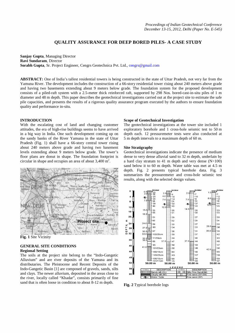
Proceedings of Indian Geotechnical Conference December 13-15, 2012, Delhi (Paper No. E-545)
QUALITY ASSURANCE FOR DEEP BORED PILES- A CASE STUDY Sanjay Gupta, Managing Director Ravi Sundaram, Director Sorabh Gupta, Sr. Project Engineer, Cengrs Geotechnica Pvt. Ltd., [email protected] ABSTRACT: One of India’s tallest residential towers is being constructed in the state of Uttar Pradesh, not very far from the Yamuna River. The development includes the construction of a 66-story residential tower rising about 240 meters above grade and having two basements extending about 9 meters below grade. The foundation system for the proposed development consists of a piled-raft system with a 2.5-meter thick reinforced raft, supported by 298 Nos. bored-cast-in-situ piles of 1 m diameter and 48 m depth. This paper describes the geotechnical investigations carried out at the project site to estimate the safe pile capacities, and presents the results of a rigorous quality assurance program executed by the authors to ensure foundation quality and performance in-situ. INTRODUCTION With the escalating cost of land and changing customer attitudes, the era of high-rise buildings seems to have arrived in a big way in India. One such development coming up on the sandy banks of the River Yamuna in the state of Uttar Pradesh (Fig. 1) shall have a 66-story central tower rising about 240 meters above grade and having two basement levels extending about 9 meters below grade. The tower’s floor plans are donut in shape. The foundation footprint is circular in shape and occupies an area of about 3,400 m2.
Fig. 1 Site Vicinity GENERAL SITE CONDITIONS Regional Setting The soils at the project site belong to the “Indo-Gangetic Alluvium” and are river deposits of the Yamuna and its distributaries. The Pleistocene and Recent Deposits of the Indo-Gangetic Basin [1] are composed of gravels, sands, silts and clays. The newer alluvium, deposited in the areas close to the river, locally called “Khadar”, consists primarily of fine sand that is often loose in condition to about 8-12 m depth.
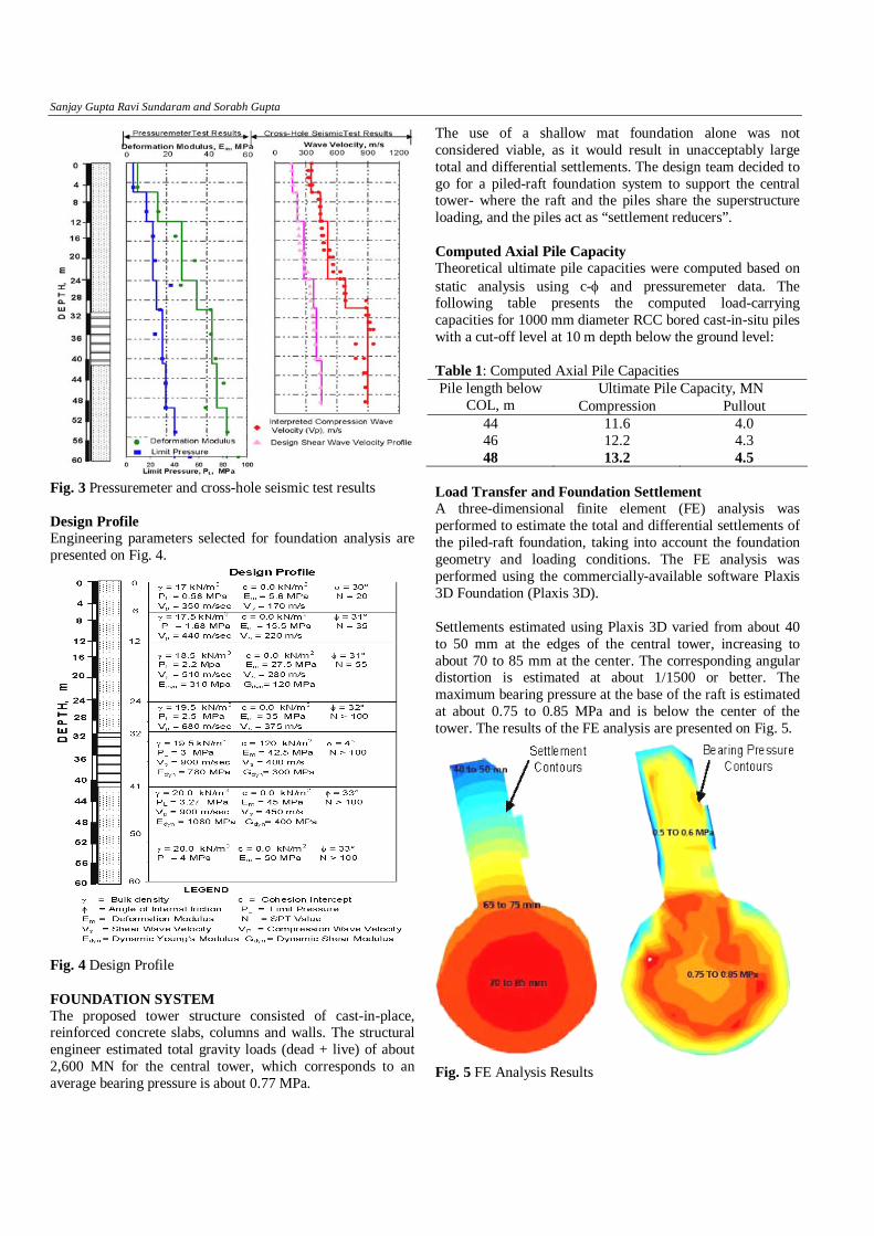
Scope of Geotechnical Investigation The geotechnical investigations at the tower site included 1 exploratory borehole and 1 cross-hole seismic test to 50 m depth each. 12 pressuremeter tests were also conducted at 5 m depth intervals to a maximum depth of 60 m. Site Stratigraphy Geotechnical investigations indicate the presence of medium dense to very dense alluvial sand to 32 m depth, underlain by a hard clay stratum to 41 m depth and very dense (N>100) sand below it to 60 m depth. Water table was met at 4.5 m depth. Fig. 2 presents typical borehole data. Fig. 3 summarizes the pressuremeter and cross-hole seismic test results, along with the selected design values.
Fig. 2 Typical borehole logs
Project site
Sanjay Gupta Ravi Sundaram and Sorabh Gupta
Fig. 3 Pressuremeter and cross-hole seismic test results Design Profile Engineering parameters selected for foundation analysis are presented on Fig. 4.
Fig. 4 Design Profile FOUNDATION SYSTEM The proposed tower structure consisted of cast-in-place, reinforced concrete slabs, columns and walls. The structural engineer estimated total gravity loads (dead + live) of about 2,600 MN for the central tower, which corresponds to an average bearing pressure is about 0.77 MPa.
The use of a shallow mat foundation alone was not considered viable, as it would result in unacceptably large total and differential settlements. The design team decided to go for a piled-raft foundation system to support the central tower- where the raft and the piles share the superstructure loading, and the piles act as “settlement reducers”. Computed Axial Pile Capacity Theoretical ultimate pile capacities were computed based on static analysis using c-φ and pressuremeter data. The following table presents the computed load-carrying capacities for 1000 mm diameter RCC bored cast-in-situ piles with a cut-off level at 10 m depth below the ground level: Table 1: Computed Axial Pile Capacities
Ultimate Pile Capacity, MN Pile length below COL, m Compression Pullout
44 11.6 4.0 46 12.2 4.3 48 13.2 4.5
Load Transfer and Foundation Settlement A three-dimensional finite element (FE) analysis was performed to estimate the total and differential settlements of the piled-raft foundation, taking into account the foundation geometry and loading conditions. The FE analysis was performed using the commercially-available software Plaxis 3D Foundation (Plaxis 3D). Settlements estimated using Plaxis 3D varied from about 40 to 50 mm at the edges of the central tower, increasing to about 70 to 85 mm at the center. The corresponding angular distortion is estimated at about 1/1500 or better. The maximum bearing pressure at the base of the raft is estimated at about 0.75 to 0.85 MPa and is below the center of the tower. The results of the FE analysis are presented on Fig. 5.
Fig. 5 FE Analysis Results

Quality Assurance for Deep Bored Piles: A Case Study
The results of the FE analysis, as well as preliminary results of the structural analysis, showed that about 75 percent of the superstructure load is transferred to the piles, and about 25 percent is taken by the soil subgrade. The equivalent pile springs were determined from the load applied to each pile and the associated settlement at the pile head. Selected Foundation System The final foundation system for the proposed tower was a piled-raft system with a 2.5-meter thick reinforced concrete raft, supported by 298 bored-cast-in-situ piles of 1000 mm diameter and extending to 48 m depth. The pile cut-off level was at 10 m depth. QUALITY ASSURANCE TESTS ON PILES Extensive quality assurance tests were carried out to ensure that the piles behave as planned. Where problems were identified, necessary remedial measures were carried out. The following tests were carried out: • Low Strain Pile Integrity Tests (PIT) • Static load tests – initial and routine tests • High Strain Dynamic Pile Load tests (HSDLT) Low Strain Pile Integrity Tests Low-strain pile integrity tests (PIT) were performed on all the piles installed at the site using a special hand-held hammer (8 lbs) struck on the pile head. An accelerometer placed on the pile records the sonic response [2]. The PIT results indicated significant impedance changes along the pile shaft, particularly at shallow depths of about 2.5-4.5 m. This was confirmed by excavating and exposing a few pile to about 5 m depth (Fig. 6). Further, most of the PIT results showed a weak toe response, which was attributed to low pile end-bearing.
Fig. 6 PIT results confirmed by excavation (Pile No. 1103)
Static and Dynamic Pile Load Tests Initial (static) load tests on 1 m diameter, 25 m long test piles installed at the project site indicated a total pile settlement of less than 25 mm at the test load of 10 MN (Fig. 7).
Fig. 7 Initial (static) load tests on 25 m long, 1m dia piles Static load tests were also carried out on 3 Nos. production piles (48 m length) by kentledge method. Further, 6 Nos. high-strain dynamic load tests [3] were also carried out using a 200 kN, guided weight free-falling from 0.5-3 m height and 16-channel Pile Driving Analyzer (PDA) equipment. A photograph showing the test setup is presented on Fig. 8. The data from the dynamic tests was analyzed using CAPWAP® software to assess the equivalent load-settlement curves. Fig. 9 presents the interpreted static load-settlement behaviour of the piles from the high strain dynamic tests, along with load settlement curves from static load tests.
Fig. 8 Dynamic Pile Load Test Setup

Sanjay Gupta Ravi Sundaram and Sorabh Gupta
Fig. 9 Load-Settlement Curves–Static and Dynamic Based on the static / dynamic load test results, it is observed that the total settlement of the 48 m long production piles under a test load of 10 MN is typically about 40-60 mm, which is twice the settlement of the 25 m long initial piles (Fig. 7). Based on the PIT and load test results, as well as pour card information, the authors concluded that the poor pile performance was due to structural defects and variations in the pile concrete, as well as “soft toe condition” owing to poor bottom cleaning. Concrete Coring The PIT and PDA tests indicated that the quality of concrete in some of the piles may be suspect. To confirm the concrete quality, the coring of NX size was done using a hydraulic rotary drilling rig. Fig. 10 presents typical concrete core for Pile 1079 at the terminal depth.
Fig. 10 Concrete Core – Pile No. 1097 (Note the discontinuities and soft zones) To assess the concrete quality with depth, PIT results were compared with the core recovery (%). As may be seen in Fig.
11, the zones of poor core recovery correspond to early reflections from the discontinuities in the PIT data.
Fig. 11 Comparison of PIT with concrete core recovery CONCLUDING REMARKS The quality assurance program proved that the piles construction at the site were unlikely to behave as per design. The foundation analysis was repeated considering lowered pile stiffness (corresponding to nil end-bearing). Additional piles were constructed under the raft to compensate for the loss in the foundation bearing capacity. The quality assurance program executed at the project site revealed glaring inadequacies in the foundation construction at a major project site, and possibly helped avert a major catastrophe. The authors are strongly of the opinion that foundation design is incomplete without a well-planned, comprehensive foundation testing program executed by independent agencies of technical repute. ACKNOWLEDGEMENTS The authors are grateful to M/s. Supertech Pvt. Ltd. and M/s. Billimoria Pvt. Ltd. for giving Cengrs Geotechnica Pvt. Ltd. an opportunity to perform the geotechnical investigation and foundation testing at the site. REFERENCES 1. Krishnan, M. (2008), Geosynthetics Practices, 3rd Ed.,
Prentice Hall, New Delhi, India. 2. Sorabh Gupta, Ravi Sundaram & Sanjay Gupta, (2008),
Pile Integrity Testing for Monitoring Pile Construction, Geosymposium 2008,Indian Geotechnical Society Delhi Chapter, pp 173-178.
3. ASTM D4945-08, Standard Test Method for High-Strain Dynamic Testing of Piles
33.5 m
44.5 m Soil