Embed Size (px)
Citation preview

Qualified Partner Programme QPP
Fiber Optic Connector Theory
Felice Guarna

Fiber Optic Connector Theory / Page 2
Fiber optic theory / connection technique
Basically, there are 3 possibilities to join optical fiber:Detachable connection e.g. plugged connection
Quasi-detachable connection e.g. mechanical splice
Non-detachable connection e.g. fusion splice
Which connection technique is being employed depends on:the reliability or requirement of the connection
the required or necessary flexibility
the costs

Fiber Optic Connector Theory / Page 3
OverviewCriteria's Detachable2 Quasi – Detachable Not – DetachableInsertion loss αs in [dB] 0,05 < αs < 0,75 0,1 < αs < 0,5 0,05 < αs < 0,2
Return loss αR in [dB] 15 < αR < 80 αR < 40 αR < 80Mounting on field Appropriate Appropriate AppropriateRepeated disconnect and connect Very simple, without equipment
and without the need of qualifiedpersonnel
Simple, simple equipment andqualified personnel needed.
expensive, high-quality equipmentand need of very high qualifiedpersonnel.
Reliability / Lifespan ca. 500 - 2000 Pcs. Cycles Not Very high
Costs• Equipment• Initial Installation• Repeated disconnect and connect
mediumhighvery low
lowhighlow
highlowhigh
Alignment principe Pins / sleeve (mech.) V – groove (mech.) Substance conclusive
Fiber contact As usually a Physical Contact Immersion betweenseparation-surfaces Substance conclusive
2
D ependent on the C onnecto r T ype and po lish ing (P C , S P C , U P C , A P V = H R L)
P C P hysica l C on tact, R e tu rn loss of approxim ate ly 30 dB , can be reached by m anua l po lish ingS P C S uper P hysica l C on tact, R e tu rn loss of approxim ate ly 40dB , can be reached by m ach ine po lish ingU P C U ltra P hysica l C on tact, R e tu rn loss of approxim ate ly 50 dB , can be reached by m ach ine po lish ing and op tica l testing of the fibe r position ingAP C (H R L) A ngle P hysica l C on tact (H igh R etu rn Loss), R e tu rn loss of approxim ate ly 60 dB , can be reached by m ach ine po lish ing (usua lyl R . 8° A ngle Po lished)
Fiber Optic Connector Theory / Page 4
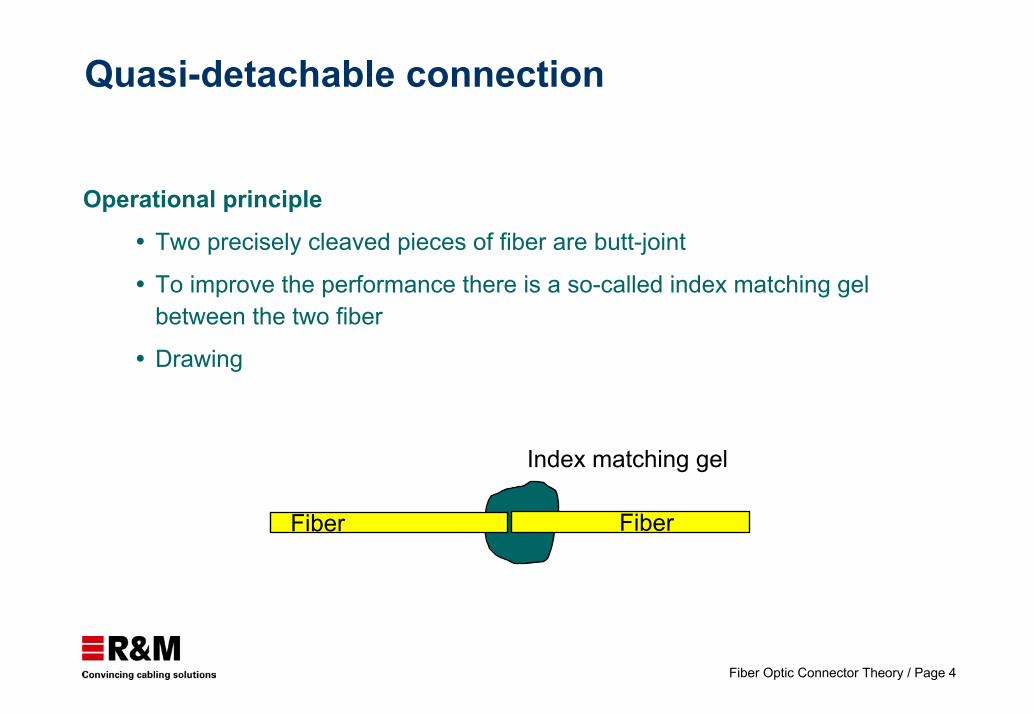
Quasi-detachable connection
Operational principleTwo precisely cleaved pieces of fiber are butt-joint
To improve the performance there is a so-called index matching gel between the two fiber
Drawing
Index matching gel
Fiber Fiber

Fiber Optic Connector Theory / Page 5
Non-detachable connection
Operational principleThe cleaned and cleaved fiber are brought together as closely as possible in a splicing device (if possible without horizontal or vertical displacement). Subsequently, the splice area is protected with a so-called splice protection and then deposited.
Direction

Fiber Optic Connector Theory / Page 6
Detachable connection
Operating principleConnector/adapter/connector principle
There are various types of end face polishes, differing in performance (RL, IL). They are:
Flat
Physical contact (PC)
Angled physical contact (APC)
Lens

Fiber Optic Connector Theory / Page 7
Insertion loss
4% reflection on each endface is 0.36 dB loss
ExtrinsicRelative position:
Axial separation
Preparation of end face:
Surface roughtness
Angle
λ/4
0.2°

Fiber Optic Connector Theory / Page 8
Insertion loss
Extrinsic
Relative position:
Lateral off-set
Axial tilt

Fiber Optic Connector Theory / Page 9
Insertion loss
IntrinsicDifferences in:
Core diameter
Numericalaperture
Refractiveindex profile
Θ Θ

Fiber Optic Connector Theory / Page 10
Flat polish
Non - butting ferrulesNo physical contact
4% reflection on each endface results in 0.36 dB of loss
Transmission specifications
Insertion lossReturn loss
< 1.0 dB~ 15 dB

Fiber Optic Connector Theory / Page 11
Physical contact (PC) polish
Butting ferrulesSpherical physical contact
Transmission specifications
Insertion lossReturn loss
< 0.5 dB> 20 dB
Radius 10 - 25 mm

Fiber Optic Connector Theory / Page 12
Angled physical contact (APC) polish
Butting ferrulesAngled spherical physical contact
Radius 5 - 12 mm
Angle 8 - 12°
Transmission specifications
Insertion lossReturn loss
< 0.3 dB> 60 dB

Fiber Optic Connector Theory / Page 13
Connector cleaning

Fiber Optic Connector Theory / Page 14
Fiber optic theory / connection technique
The 2 connectors are plugged into 1 adapter
Structure principle (of 2.5 mm ferrule)
Alignment technologiesresilient sleeve
Ferrule Ferrule
Sleeve
Tolerance fieldsFerrule 2.4985 - 2.4995 mmSleeve gauge retention force 2.9 - 5.9 N
MaterialsFerrule ceramic (Zirconia) Sleeve ceramic (Zirconia) ⇒ SM
PhBr ⇒ MM
Fiber
Sleeve

Fiber Optic Connector Theory / Page 15
Multimode connector set
Specifications:
Coupling mechanism
Configuration
Ferrule dimension
Fiber category
Fiber retention
Cable retention
Optical coupling
Alignment
Bayonet
Plug-adapter-plug
2.500 mm nominal
ceramic
A, IEC 60793-2
Adhesive
Crimp
Physical contact (PC)
Resilient sleeve spring loaded ferrule
ST-PC(ATT)

Fiber Optic Connector Theory / Page 16
Multimode / Single mode connector set
Specifications:Coupling mechanism
Configuration
Ferrule dimension
Fiber category
Fiber retention
Cable retention
Optical coupling
Alignment
Colour coding
Push-PullPlug-adapter-plug2.500 mm nominalceramicA, IEC 60793-2B, IEC 60793-2AdhesiveCrimpPhysical contact (PC)Resilient sleeveSpring loaded ferruleBeige: Multimode, Blue: Single mode
SC- DuplexJapan (NTT)
Singlemode version shown above

Fiber Optic Connector Theory / Page 17
Other connectors used for LAN applicationsFDDI connectors
FDDI/ST adaptersFDDI/FDDI adapters
ESCON connectors (IBM applications)ESCON/ST adaptersESCON/ESCON adapters
FC/PC connectorsFC/FC adaptersFC/ST adapters
SMA connectorsSM/SMA adapters

Fiber Optic Connector Theory / Page 18
New standard for connectors
Small form factor connectors

Fiber Optic Connector Theory / Page 19
New standard for connectors?
SC-DC/QCCompact SC
LX-5MT-RJ
LC
Opti-Jack
SGMini-MPO
Which one???

Fiber Optic Connector Theory / Page 20
Duplex SC
Duplex SC is "The" approved connector for cabling solutions!!If you want to have a standard compliant installation, you have to use a Duplex
SC solution.....
....but....
What about the SFF?Due to insufficient support for a change they‘d initially ALL been rejected by the TIA/EIA and ISO/IEC 11801.
They have now been recognised!!!!

Fiber Optic Connector Theory / Page 21
Shall we forget about SFF connectors?
Definitely not !!!

Fiber Optic Connector Theory / Page 22
Predominant SFF connectors
MT-RJ
LC
SC-DC
VF-45

Fiber Optic Connector Theory / Page 23
SFF mechanical comparison
LC 6.25 mm
2
Ceramic
Bore & Ferrule
Ø 1.25 mm
11.1 mm
5.7 mm
14.6 mm
Duplex Zip
Pot & Polish
2 RJ Latches
MT-RJ0.75 mm
1
Plastic
Pin & Ferrule
2.5 x 4.4 mm
7.2 mm
5.7 mm
14.0 mm
Duplex / Ribbon
Pre-polish Crimp
1 RJ Latch
SC-DC0.75 mm
1
Plastic
Rail & Ferrule
2.5 mm
11 mm
7.5 mm
12.7 mm
Duplex / Ribbon
Pre-polish Stub
SC Push Pull
VF-454.5 mm
NA
None
V-Groove
NA
12.1 mm
8 mm
21 mm
GGP Polymer Coated
Cleave & Polish Socket
1 RJ Latch
Fiber spacing
# of ferrules
Ferrule material
Alignment
Ferule size
Width
Height
Length
Fiber cable
Field termination
Latch style

Fiber Optic Connector Theory / Page 24
SFF optical loss comparison
A.) SC Duplex B.) SC-DC C.) VF-45
D.) MT-RJ I E.) MT-RJ II
F.) LC I G.) LC II
000000
0000
00 00
--0.80.8 --0.80.8 --0.80.8
--0.80.8 --0.80.8
--0.80.8 --0.80.8
D & E are different connector hardware’s from different manufacturesF & G is the same connector but from different manufactures

Fiber Optic Connector Theory / Page 25
MT-RJ connectors?
SFF connector with dimensions and locking system like RJ45
No ceramic ferrule=> lower cost
High port density, half size of Duplex SC
Multimode or singlemode
Male and female connectors + adapter
Two or four channels
Meet ISO/IEC 11801 and TIA/EIA 568A specs
RJ latching provides audible and tactile feedback when mated
Insertion loss typical: 0.2dB.

Fiber Optic Connector Theory / Page 26
Structure principle (e.g. of multi-fiber cables)
New alignment technologiesV - Groove
Materials
V - Groove
aligner
silicium wafer
tungsten carbide
Aligner Fiber V - Groove

Fiber Optic Connector Theory / Page 27
SC-RJ connectors?SFF connector with dimensions and locking system like RJ45
Ceramic ferrule -> Well known on the market
High port density, approximately half size of Duplex SC
Multimode or Single mode
Backward compatible to SC
One connector type + adapter
Meet ISO/IEC 11801 and TIA/EIA 568A specs
SCcompact (or SC-RJ) is based on the SC connector
(according to. CECC 86265-xxx, IEC 60874-14)Also possible to connect an SC Simplex
Insertion loss typical: < 0.2dB.

Fiber Optic Connector Theory / Page 28
Which Termination technique?
Fiber fixed to ferrule by adhesive and polishing
Fiber mechanically fixed to ferrule and polishing
Fiber mechanically fixed and no polishing

Fiber Optic Connector Theory / Page 29
Adhesive fixing
EpoxyTwo compounds
Precise dosage
Short time to fix after mixing
Curing necessary
AnaerobicTwo compounds
No precise dosage
Time and curing less critical

Fiber Optic Connector Theory / Page 30
Adhesive fixing
Ultra-violetSingle compound
Special connector (ferrule transmitting UV)
UV curing and power
Pre-injectedCompound melting oven
Power for oven
No critical curing
Expiring connector (compound limited life)

Fiber Optic Connector Theory / Page 31
Mechanical connectors
Fiber mechanically retained inside ferrule and polishingQuick termination
Same polishing
Mechanical splice with pigtail (no polishing)
Quick termination
No polishing

Fiber Optic Connector Theory / Page 32
Alternatives
Quality and reliabilityWorkmanship
SkillTimeChemicals
ExpiringConnectorsChemicals
CostConnectorsTermination time
Tools

Fiber Optic Connector Theory / Page 33
Any Questions?