Embed Size (px)
Citation preview

2
QUADRA-CHEK 2000
InstallationsanleitungInstallation InstructionsGuide d’installationIstruzioni di installazioneManual de instrucciones deinstalaciónInstallatiehandleidingInstalační návodInstrukcja instalacjiInstruções de instalaçãoKurulum kılavuzu設置説明書설치 설명서安装说明安裝手冊
06/2018
Installationsanleitung.............................................................................................................. 5
Installation Instructions........................................................................................................ 17
Guide d’installation...............................................................................................................29
Istruzioni di installazione...................................................................................................... 42
Manual de instrucciones de instalación...............................................................................54
Installatiehandleiding............................................................................................................ 67
Instalační návod................................................................................................................... 79Instrukcja instalacji................................................................................................................91Instruções de instalação.................................................................................................... 103
Kurulum kılavuzu................................................................................................................ 115設置説明書................................................................................................ 127설치 설명서......................................................................................................................................................... 139安装说明.................................................................................................................................................151安裝手冊....................................................................................................................................................... 163

4
A
AC 100 V ... 240 V50 Hz ... 60 Hz
(max. 38 W)
HEIDENHAIN
X113
X3
X108
X107
X2
X1
X116
X100
X32
21
3
4
5
67
8
C
D E

de
HEIDENHAIN | QUADRA-CHEK 2000 | Installationsanleitung | 06/2018 5
1 Grundlegendes
1.1 Überblick
Dieses Kapitel beinhaltet Informationen über das
vorliegende Produkt und die vorliegende Anleitung.
1.2 Informationen zum Produkt
Produktbezeichnung ID Index
QUADRA-CHEK 2000 1089180-xx ---
Das Typenschild befindet sich auf der Geräterückseite.
Beispiel:
2
3
1
1 Produktbezeichnung
2 Index
3 Identnummer (ID)
1.3 Dokumentation zum Produkt
1.3.1 Gültigkeit der Dokumentation
Vor Gebrauch der Dokumentation und des Geräts
müssen Sie überprüfen, ob Dokumentation und Gerät
übereinstimmen.
Die in der Dokumentation angegebene Identnummer
und den Index mit den Angaben auf dem Typenschild
des Geräts vergleichen
Wenn die Identnummern und Indizes übereinstimmen,
ist die Dokumentation gültig
Wenn die Identnummern und Indizes nicht
übereinstimmen und die Dokumentation
somit nicht gültig ist, finden Sie die
aktuelle Dokumentation zum Gerät unter
www.heidenhain.de.
1.3.2 Hinweise zum Lesen der Dokumentation
WARNUNG
Unfälle mit tödlichem Ausgang, Verletzungen
oder Sachschäden bei Nichtbeachtung der
Dokumentation!
Wenn Sie die Dokumentation nicht beachten, können
Unfälle mit tödlichem Ausgang, Verletzungen von
Personen oder Sachschäden entstehen.
Dokumentation sorgfältig und vollständig lesen
Dokumentation aufbewahren zum Nachschlagen
Die folgende Tabelle enthält die Bestandteile der
Dokumentation in der Reihenfolge ihrer Priorität beim
Lesen.
Dokumentation Beschreibung
Addendum Ein Addendum ergänzt oder
ersetzt die entsprechenden Inhal-
te der Betriebsanleitung und ggf.
auch der Installationsanleitung.
Ist ein Addendum in der Liefe-
rung enthalten, hat es die höchste
Priorität beim Lesen. Alle übrigen
Inhalte der Dokumentation behal-
ten ihre Gültigkeit.
Installationsanlei-
tung
Die Installationsanleitung enthält
alle Informationen und Sicherheits-
hinweise, um das Gerät sachge-
recht zu montieren und zu installie-
ren. Als Auszug aus der Betriebs-
anleitung ist die Installationsanlei-
tung in jeder Lieferung enthalten.
Die Installationsanleitung hat die
zweithöchste Priorität beim Lesen.
Betriebsanleitung Die Betriebsanleitung enthält alle
Informationen und Sicherheits-
hinweise, um das Gerät sachge-
recht und bestimmungsgemäß
zu betreiben. Die Betriebsan-
leitung ist auf dem mitgeliefer-
ten Speichermedium enthalten
und kann auch im Downloadbe-
reich von www.heidenhain.de
heruntergeladen werden. Vor der
Inbetriebnahme des Geräts muss
die Betriebsanleitung gelesen
werden.
Die Betriebsanleitung hat die dritt-
höchste Priorität beim Lesen.
Änderungen gewünscht oder den Fehlerteufel
entdeckt?
Wir sind ständig bemüht, unsere Dokumentation für Sie
zu verbessern. Helfen Sie uns dabei und teilen uns bitte
Ihre Änderungswünsche unter folgender E-Mail-Adresse
mit:

de
6 HEIDENHAIN | QUADRA-CHEK 2000 | Installationsanleitung | 06/2018
1.3.3 Aufbewahrung und Weitergabe der
Dokumentation
Die Anleitung muss in unmittelbarer Nähe des
Arbeitsplatzes aufbewahrt werden und dem gesamten
Personal jederzeit zur Verfügung stehen. Der Betreiber
muss das Personal über den Aufbewahrungsort dieser
Anleitung informieren. Wenn die Anleitung unleserlich
geworden ist, dann muss durch den Betreiber Ersatz beim
Hersteller beschafft werden.
Bei Übergabe oder Weiterverkauf des Geräts an Dritte
müssen die folgenden Dokumente an den neuen Besitzer
weitergegeben werden:
Addendum (falls mitgeliefert)
Betriebsanleitung
1.4 Zu dieser Anleitung
Diese Anleitung enthält alle Informationen und
Sicherheitshinweise, um das Gerät sachgerecht zu
montieren und zu installieren.
1.4.1 Dokumententyp
Installationsanleitung
Die vorliegende Anleitung ist die Installationsanleitung
des Produkts.
Die Installationsanleitung
ist ein Auszug aus der Betriebsanleitung des Produkts
ist am Produktlebenszyklus orientiert
enthält alle notwendigen Informationen und Sicher-
heitshinweise, um das Produkt sachgerecht und
bestimmungsgemäß zu montieren und zu installieren
enthält keine Informationen, die über die Installation
des Produkts hinausgehen, wie z. B. Inbetriebnahme
des Produkts oder Betrieb des Produkts
1.4.2 Zielgruppen der Anleitung
Die vorliegende Anleitung muss von jeder Person gelesen
und beachtet werden, die mit einer der folgenden
Arbeiten betraut ist:
Montage
Installation
1.4.3 Verwendete Hinweise
Sicherheitshinweise
Sicherheitshinweise warnen vor Gefahren im Umgang mit
dem Gerät und geben Hinweise zu deren Vermeidung.
Sicherheitshinweise sind nach der Schwere der Gefahr
klassifiziert und in die folgenden Gruppen unterteilt:
GEFAHR
Gefahr signalisiert Gefährdungen für Personen. Wenn
Sie die Anleitung zum Vermeiden der Gefährdung nicht
befolgen, dann führt die Gefährdung sicher zum Tod
oder schweren Körperverletzungen.
WARNUNG
Warnung signalisiert Gefährdungen für Personen.
Wenn Sie die Anleitung zum Vermeiden der
Gefährdung nicht befolgen, dann führt die Gefährdung
voraussichtlich zum Tod oder schweren
Körperverletzungen.
VORSICHT
Vorsicht signalisiert Gefährdungen für Personen. Wenn
Sie die Anleitung zum Vermeiden der Gefährdung nicht
befolgen, dann führt die Gefährdung voraussichtlich
zu leichten Körperverletzungen.
HINWEIS
Hinweis signalisiert Gefährdungen für Gegenstände
oder Daten. Wenn Sie die Anleitung zum Vermeiden
der Gefährdung nicht befolgen, dann führt die
Gefährdung voraussichtlich zu einem Sachschaden.
Informationshinweise
Informationshinweise gewährleisten einen fehlerfreien
und effizienten Einsatz des Geräts. Informationshinweise
sind in die folgenden Gruppen unterteilt:
Das Informationssymbol steht für einen Tipp.
Ein Tipp gibt wichtige zusätzliche oder
ergänzende Informationen.
Das Zahnradsymbol zeigt an, dass die
beschriebene Funktion maschinenabhängig
ist, z. B.:
Ihre Maschine muss über eine notwendige
Software- oder Hardwareoption verfügen
Das Verhalten der Funktionen hängt
von konfigurierbaren Einstellungen der
Maschine ab
Das Buchsymbol steht für einen Querverweis
zu externen Dokumentationen, z. B. der
Dokumentation Ihres Maschinenherstellers
oder eines Drittanbieters.

de
HEIDENHAIN | QUADRA-CHEK 2000 | Installationsanleitung | 06/2018 7
1.4.4 Textauszeichnungen
In dieser Anleitung werden folgende Textauszeichnungen
verwendet:
Darstellung Bedeutung
...
...
kennzeichnet einen Handlungsschritt und
das Ergebnis einer Handlung
Beispiel:
Auf OK tippen
Die Meldung wird geschlossen
...
...
kennzeichnet eine Aufzählung
Beispiel:
Schnittstelle TTL
Schnittstelle EnDat
...
fett kennzeichnet Menüs, Anzeigen und
Schaltflächen
Beispiel:
Auf Herunterfahren tippen
Das Betriebssystem fährt herunter
Gerät am Netzschalter ausschalten
2 Sicherheit
2.1 Überblick
Dieses Kapitel beinhaltet wichtige Informationen zur
Sicherheit, um das Gerät ordnungsgemäß zu montieren
und zu installieren.
2.2 Allgemeine Sicherheitsvorkehrungen
Für den Betrieb des Systems gelten die allgemein
anerkannten Sicherheitsvorkehrungen wie sie
insbesondere beim Umgang mit stromführenden
Geräten erforderlich sind. Nichtbeachtung dieser
Sicherheitsvorkehrungen kann Schäden am Gerät oder
Verletzungen zur Folge haben.
Die Sicherheitsvorschriften können je nach Unternehmen
variieren. Im Falle eines Konflikts zwischen dem Inhalt
dieser Anleitung und den internen Regelungen eines
Unternehmens, in dem dieses Gerät verwendet wird,
gelten die strengeren Regelungen.
2.3 Bestimmungsgemäße Verwendung
Die Geräte der Baureihe QUADRA-CHEK 2000 sind
hochwertige digitale Auswerte-Elektroniken für eine
Erfassung von 2D-Konturelementen in messtechnischen
Anwendungen. Die Geräte werden vorwiegend an
Messmaschinen und Profilprojektoren eingesetzt.
Die Geräte dieser Baureihe
dürfen nur in gewerblichen Anwendungen und im
industriellen Umfeld eingesetzt werden
müssen für eine bestimmungsgemäße Verwendung
auf einen geeigneten Standfuß oder Halter montiert
sein
sind für die Verwendung in Innenräumen und in einer
Umgebung vorgesehen, in der die Belastung durch
Feuchtigkeit, Schmutz, Öl und Schmiermitteln den
Vorgaben in den technischen Daten entspricht
Die Geräte unterstützen die Verwendung von
Peripheriegeräten verschiedener Hersteller.
HEIDENHAIN kann keine Aussagen zur
bestimmungsgemäßen Verwendung dieser
Geräte treffen. Die Informationen zur
bestimmungsgemäßen Verwendung in den
zugehörigen Dokumentationen müssen
beachtet werden.
de
8 HEIDENHAIN | QUADRA-CHEK 2000 | Installationsanleitung | 06/2018
2.4 Bestimmungswidrige Verwendung
Unzulässig für alle Geräte der Baureihe QUADRA-CHEK
2000 sind insbesondere folgende Anwendungen:
Einsatz und Lagerung außerhalb der Betriebsbe-
dingungen gemäß "Technische Daten"
Einsatz im Freien
Einsatz in explosionsgefährdeten Bereichen
Einsatz der Geräte der Baureihe QUADRA-CHEK 2000
als Bestandteil einer Sicherheitsfunktion
2.5 Qualifikation des Personals
Das Personal für Montage und Installation muss die
entsprechende Qualifikation für diese Arbeiten aufweisen
und sich mit Hilfe der Dokumentation des Geräts und der
angeschlossenen Peripherie ausreichend informiert haben.
Die Personalanforderungen, die für die einzelnen
Tätigkeiten am Gerät notwendig sind, sind in den
entsprechenden Kapiteln dieser Anleitung angegeben.
Nachfolgend sind die Personengruppen hinsichtlich ihrer
Qualifikationen und Aufgaben näher spezifiziert.
Fachpersonal
Das Fachpersonal wird vom Betreiber in der erweiterten
Bedienung und Parametrierung ausgebildet. Das
Fachpersonal ist aufgrund seiner fachlichen Ausbildung,
Kenntnisse und Erfahrung sowie Kenntnis der
einschlägigen Bestimmungen in der Lage, die ihm
übertragenen Arbeiten hinsichtlich der jeweiligen
Applikation auszuführen und mögliche Gefahren
selbstständig zu erkennen und zu vermeiden.
Elektrofachkraft
Die Elektrofachkraft ist aufgrund ihrer fachlichen
Ausbildung, Kenntnisse und Erfahrungen sowie Kenntnis
der einschlägigen Normen und Bestimmungen in der
Lage, Arbeiten an elektrischen Anlagen auszuführen
und mögliche Gefahren selbstständig zu erkennen und
zu vermeiden. Die Elektrofachkraft ist speziell für das
Arbeitsumfeld ausgebildet, in dem sie tätig ist.
Die Elektrofachkraft muss die Bestimmungen der
geltenden gesetzlichen Vorschriften zur Unfallverhütung
erfüllen.
2.6 Betreiberpflichten
Der Betreiber besitzt das Gerät und die Peripherie
oder hat beides gemietet. Er ist jederzeit für die
bestimmungsgemäße Verwendung verantwortlich.
Der Betreiber muss:
die verschiedenen Aufgaben am Gerät qualifiziertem,
geeignetem und autorisiertem Personal zuweisen
das Personal nachweisbar in die Befugnisse und
Aufgaben unterweisen
sämtliche Mittel zur Verfügung stellen, die das
Personal benötigt, um die ihm zugewiesenen
Aufgaben zu erfüllen
sicherstellen, dass das Gerät ausschließlich in
technisch einwandfreiem Zustand betrieben wird
sicherstellen, dass das Gerät gegen unbefugte
Benutzung geschützt wird
2.7 Allgemeine Sicherheitshinweise
Die Verantwortung für jedes System, in dem
dieses Produkt verwendet wird, liegt bei dem
Monteur oder Installateur dieses Systems.
Das Gerät unterstützt die Verwendung
einer Vielzahl von Peripheriegeräten
verschiedener Hersteller. HEIDENHAIN
kann keine Aussagen zu den spezifischen
Sicherheitshinweisen dieser Geräte
treffen. Die Sicherheitshinweise aus den
entsprechenden Dokumentationen müssen
beachtet werden. Falls die Dokumentationen
nicht vorliegen, müssen sie bei den
Herstellern angefordert werden.
Die spezifischen Sicherheitshinweise, die für die einzelnen
Tätigkeiten am Gerät zu beachten sind, sind in den
entsprechenden Kapiteln dieser Anleitung angegeben.
2.7.1 Symbole am Gerät
Das Gerät ist mit den folgenden Symbolen
gekennzeichnet:
Symbol Bedeutung
Beachten Sie die Sicherheitshinweise zur
Elektrik und zum Netzanschluss, bevor Sie
das Gerät anschließen.
Funktionserde-Anschluss gemäß
IEC/EN 60204-1. Beachten Sie die Hinweise
zur Installation.
Produktsiegel. Wenn das Produktsiegel
gebrochen oder entfernt wird, erlöschen die
Gewährleistung und die Garantie.

de
HEIDENHAIN | QUADRA-CHEK 2000 | Installationsanleitung | 06/2018 9
2.7.2 Sicherheitshinweise zur Elektrik
WARNUNG
Gefährlicher Kontakt mit spannungsführenden
Teilen beim Öffnen des Geräts.
Elektrischer Schock, Verbrennungen oder der Tod
können die Folge sein.
Auf keinen Fall das Gehäuse öffnen
Eingriffe nur vom Hersteller vornehmen lassen
WARNUNG
Gefahr von gefährlicher Körperdurchströmung
bei direktem oder indirektem Kontakt mit
spannungsführenden Teilen.
Elektrischer Schock, Verbrennungen oder der Tod
können die Folge sein.
Arbeiten an der Elektrik und an stromführenden
Bauteilen nur durch eine ausgebildete Fachkraft
durchführen lassen
Für Netzanschluss und alle Schnittstellenanschlüsse
ausschließlich normgerecht gefertigte Kabel und
Stecker verwenden
Defekte elektrische Bauteile sofort über den
Hersteller austauschen lassen
Alle angeschlossenen Kabel und Anschlussbuchsen
des Geräts regelmäßig prüfen. Mängel, z. B. lose
Verbindungen bzw. angeschmorte Kabel, sofort
beseitigen
HINWEIS
Beschädigung innerer Gerätebauteile!
Wenn Sie das Gerät öffnen, erlöschen die
Gewährleistung und die Garantie.
Auf keinen Fall das Gehäuse öffnen
Eingriffe nur vom Gerätehersteller vornehmen
lassen
3 Transport und Lagerung
3.1 Überblick
Dieses Kapitel beinhaltet Informationen zu Transport und
Lagerung sowie zu Lieferumfang und Zubehör des Geräts.
Die nachfolgenden Schritte dürfen nur von
Fachpersonal durchgeführt werden.
Weitere Informationen: "Qualifikation des
Personals", Seite 8
3.2 Gerät auspacken
Verpackungskarton oben öffnen
Verpackungsmaterial entfernen
Inhalt entnehmen
Lieferung auf Vollständigkeit prüfen
Lieferung auf Transportschäden kontrollieren
3.3 Lieferumfang und Zubehör
3.3.1 Lieferumfang
In der Lieferung sind die folgenden Artikel enthalten:
Bezeichnung Beschreibung
2D-Demo-Teil
Gerät
Betriebsanleitung
Installationsanleitung
Addendum (optional)

de
10 HEIDENHAIN | QUADRA-CHEK 2000 | Installationsanleitung | 06/2018
3.3.2 Zubehör
Software-Optionen müssen am Gerät über
einen Lizenzschlüssel freigeschaltet werden.
Zugehörige Hardware-Komponenten können
erst nach Freischaltung der jeweiligen
Software-Option verwendet werden.
Das nachfolgend aufgeführte Zubehör kann optional bei
HEIDENHAIN bestellt werden:
Zubehör Bezeichnung ID
zur Installation
USB-Verbindungskabel 354770-xx
Adapterstecker TTL 1089210-01
Adapterstecker 2 Vss 1089216-01
Fußschalter 681041-04
Adapterstecker 11 µAss 1089213-01
Adapterstecker 1 Vss 1089214-01
Netzkabel 223775-01
zur Montage
Halter Multi-Pos 1089230-08
Standfuß Duo-Pos 1089230-06
Standfuß Multi-Pos 1089230-07
zur Software-Option OED
Lichtwellenleiter 681049-xx
Lichwellenleiter-Verbin-
dung
681049-xx
Halter 681050-xx
3.4 Wenn ein Transportschaden vorliegt
Schaden vom Spediteur bestätigen lassen
Verpackungsmaterialien zur Untersuchung aufheben
Absender über den Schaden benachrichtigen
Händler oder Maschinenhersteller bezüglich
Ersatzteilen kontaktieren
Bei einem Transportschaden:
Die Verpackungsmaterialien zur
Untersuchung aufbewahren
HEIDENHAIN oder Maschinenhersteller
kontaktieren
Dies gilt auch für Transportschäden an
Ersatzteilanforderungen.
3.5 Wiederverpackung und Lagerung
Verpacken und lagern Sie das Gerät umsichtig und
entsprechend der hier genannten Bedingungen.
3.5.1 Gerät verpacken
Die Wiederverpackung sollte der Originalverpackung so
gut wie möglich entsprechen.
Alle Anbauteile und Staubschutzkappen am Gerät
so anbringen, wie sie bei der Lieferung des Geräts
angebracht waren oder so verpacken, wie sie verpackt
waren
Gerät so verpacken, dass
Stöße und Erschütterungen beim Transport
gedämpft werden
kein Staub und keine Feuchtigkeit eindringen
können
Alle mitgelieferten Zubehörteile in die Verpackung
legen
Weitere Informationen: "Lieferumfang und Zubehör",
Seite 9
Sämtliche im Lieferzustand beigepackte
Dokumentation beilegen
Weitere Informationen: "Aufbewahrung und
Weitergabe der Dokumentation", Seite 6
Bei Reparaturrücksendungen des Geräts zum
Kundendienst:
Das Gerät ohne Zubehör, ohne Messgeräte
und ohne Peripheriegeräte verschicken
3.5.2 Gerät lagern
Gerät wie oben beschrieben verpacken
Bestimmungen für die Umgebungsbedingungen
beachten
Weitere Informationen: "Technische Daten",
Seite 16
Gerät nach jedem Transport und nach längerer
Lagerung auf Beschädigungen prüfen

de
HEIDENHAIN | QUADRA-CHEK 2000 | Installationsanleitung | 06/2018 11
4 Montage
4.1 Überblick
Dieses Kapitel beschreibt die Montage des Geräts.
Sie finden hier Anleitungen, wie Sie das Gerät
ordnungsgemäß an Standfüße oder Halter montieren.
Die nachfolgenden Schritte dürfen nur von
Fachpersonal durchgeführt werden.
Weitere Informationen: "Qualifikation des
Personals", Seite 8
4.2 Zusammenbau des Geräts
Allgemeine Montagehinweise
Die Aufnahme für die Montagevarianten befindet sich
an der Geräterückseite. Das Befestigungslochmuster
entspricht einem Raster von 50 mm x 50 mm.
Weitere Informationen: "H", Seite 175
Das Material zur Befestigung der Montagevarianten am
Gerät ist dem Zubehör beigepackt.
Zusätzlich benötigen Sie:
Schraubendreher Torx T20
Schraubendreher Torx T25
Innensechskantschlüssel SW 2,5 (Standfuß Duo-Pos)
Material zur Befestigung auf einer Standfläche
Für die bestimmungsgemäße Verwendung
des Geräts muss das Gerät auf einen
Standfuß oder einen Halter montiert sein.
Montage am Standfuß Duo-Pos
Sie können den Standfuß Duo-Pos entweder in einer
20°-Neigung oder in einer 45°-Neigung an das Gerät
schrauben.
Wenn Sie den Standfuß Duo-Pos in der
45°-Neigung an das Gerät schrauben,
müssen Sie das Gerät am oberen Ende der
Montageschlitze befestigen. Verwenden Sie
ein Netzkabel mit abgewinkeltem Stecker.
Standfuß mit den mitgelieferten
Innensechskantschrauben M4 x 8 ISO 7380 an den
unteren Gewindebohrungen auf der Geräterückseite
befestigen
Zulässiges Anzugsdrehmoment von
2,6 Nm beachten
Standfuß über die Montageschlitze (Breite = 4,5 mm)
auf eine Standfläche schrauben
oder
Gerät frei am gewünschten Standort aufstellen
Kabel von hinten durch die beiden Stützen des
Standfußes verlegen und durch die seitlichen
Öffnungen zu den Anschlüssen führen
Weitere Informationen: "C", Seite 4
Bemaßungen des Standfußes Duo-Pos
Weitere Informationen: "J", Seite 176
4.2.1 Montage am Standfuß Multi-Pos
Standfuß mit den mitgelieferten Senkkopfschrauben
M4 x 8 ISO 14581 (schwarz) an den
Gewindebohrungen auf der Geräterückseite befestigen
Zulässiges Anzugsdrehmoment von
2,6 Nm beachten
Optional Standfuß mit zwei M5-Schrauben von unten
an eine Standfläche schrauben
Gewünschten Neigungswinkel einstellen
Standfuß fixieren: Schraube T25 festziehen
Anzugsdrehmoment für die
Schraube T25 beachten
Empfohlenes Anzugsdrehmoment:
5,0 Nm
Maximal zulässiges Anzugs-
drehmoment: 15,0 Nm
Kabel von hinten durch die beiden Stützen des
Standfußes verlegen und durch die seitlichen
Öffnungen zu den Anschlüssen führen
Weitere Informationen: "D", Seite 4
Bemaßungen des Standfußes Multi-Pos
Weitere Informationen: "K", Seite 176

de
12 HEIDENHAIN | QUADRA-CHEK 2000 | Installationsanleitung | 06/2018
4.2.2 Montage am Halter Multi-Pos
Halter mit den mitgelieferten Senkkopfschrauben
M4 x 8 ISO 14581 (schwarz) an den
Gewindebohrungen auf der Geräterückseite befestigen
Zulässiges Anzugsdrehmoment von
2,6 Nm beachten
Halter mit der mitgelieferten M8-Schraube, den
Scheiben, dem Handgriff und der M8-Sechskantmutter
auf einen Arm montieren
Gewünschten Neigungswinkel einstellen
Halter fixieren: Schraube T25 festziehen
Anzugsdrehmoment für die
Schraube T25 beachten
Empfohlenes Anzugsdrehmoment:
5,0 Nm
Maximal zulässiges Anzugs-
drehmoment: 15,0 Nm
Kabel von hinten durch die beiden Stützen des Halters
verlegen und durch die seitlichen Öffnungen zu den
Anschlüssen führen
Weitere Informationen: "E", Seite 4
Bemaßungen des Halters Multi-Pos
Weitere Informationen: "L", Seite 177
5 Installation
5.1 Überblick
Dieses Kapitel beschreibt die Installation des Geräts.
Sie finden hier Informationen zu den Anschlüssen
des Geräts und Anleitungen, wie Sie Peripheriegeräte
ordnungsgemäß anschließen.
Die nachfolgenden Schritte dürfen nur von
Fachpersonal durchgeführt werden.
Weitere Informationen: "Qualifikation des
Personals", Seite 8
5.2 Allgemeine Hinweise
HINWEIS
Störungen durch Quellen hoher
elektromagnetischer Emission!
Peripheriegeräte wie Frequenzumrichter oder Antriebe
können Störungen verursachen.
Um die Störunempfindlichkeit gegenüber
elektromagnetischen Einflüssen zu erhöhen:
Optionalen Anschluss Funktionserde gemäß IEC/EN
60204-1 verwenden
Nur USB-Peripherie mit einer durchgängigen
Schirmung mittels z. B. metall-kaschierter Folie und
Metallgeflecht oder Metallgehäuse verwenden. Der
Bedeckungsgrad des Schirmgeflechts muss 85 %
oder höher sein. Der Schirm muss rundum an die
Stecker angebunden werden (360°-Anbindung).
HINWEIS
Herstellen und Lösen von Steckverbindungen!
Gefahr der Beschädigung von internen Bauteilen.
Steckverbindungen nur bei ausgeschaltetem Gerät
herstellen oder lösen

de
HEIDENHAIN | QUADRA-CHEK 2000 | Installationsanleitung | 06/2018 13
HINWEIS
Elektrostatische Entladung (ESD)!
Das Gerät enthält elektrostatisch gefährdete Bauteile,
die durch elektrostatische Entladung zerstört werden
können.
Sicherheitsvorkehrungen für die Handhabung ESD-
empfindlicher Bauteile unbedingt beachten
Anschlussstifte niemals ohne ordnungsgemäße
Erdung berühren
Bei Arbeiten an den Geräte-Anschlüssen geerdetes
ESD-Armband tragen
HINWEIS
Schäden am Gerät durch falsche Verdrahtung!
Wenn Sie Eingänge oder Ausgänge falsch verdrahten,
können Schäden am Gerät oder an Peripheriegeräten
entstehen.
Anschlussbelegungen und technische Daten des
Geräts beachten
Ausschließlich verwendete Pins oder Adern belegen
Weitere Informationen: "Technische Daten",
Seite 16
5.3 Geräte-Übersicht
Die Anschlüsse auf der Geräterückseite sind durch
Staubschutzkappen vor Verschmutzung und Beschädigung
geschützt.
HINWEIS
Verschmutzung und Beschädigung durch fehlende
Staubschutzkappen!
Wenn Sie auf nicht genutzte Anschlüsse
keine Staubschutzkappen aufsetzen, können
Anschlusskontakte in ihrer Funktion beeinträchtigt oder
zerstört werden.
Staubschutzkappen nur entfernen, wenn Mess-
oder Peripheriegeräte angeschlossen werden
Wenn ein Mess- oder Peripheriegerät entfernt
wird, Staubschutzkappe wieder auf den Anschluss
aufsetzen
Die Art der Anschlüsse für Messgeräte kann je
nach Geräte-Ausführung unterschiedlich sein.
Geräterückseite ohne Staubschutzkappen
Weitere Informationen: "A", Seite 4
Von Software-Optionen unabhängige Anschlüsse:
2 X113: 15-poliger Sub-D-Anschluss für z. B. Fußschal-
ter, Tastsysteme
Sub-D-Anschlüsse für Messgeräte, standardmäßig 2
Eingänge freigeschaltet, optional 1 weiterer Eingang
freischaltbar
X1-X3: Gerätevariante mit 15-poligen Sub-D-
Anschlüssen für Messgeräte mit 1 VSS-Schnittstelle
X21-X23: Gerätevariante mit 9-poligen Sub-D-
Anschlüssen für Messgeräte mit TTL-Schnittstelle
3
X1, X2, X21: Gerätevariante mit zwei 15-poligen Sub-
D-Anschlüssen für Messgeräte mit 1 VSS-Schnittstelle
und einem 9-poligen Sub-D-Anschluss für Messgerä-
te mit TTL-Schnittstelle
RJ45-Ethernet-Anschluss4
X116: Anschluss für Kommunikation und Datenaus-
tausch mit Folgesystemen bzw. PC
USB-Anschluss5
X32: USB 2.0 Hi-Speed-Anschluss (Typ A) für Drucker,
Eingabegeräte oder USB-Massenspeicher
6 Funktionserde-Anschluss gemäß IEC/EN 60204-1
7 X100: Netzschalter und Netzanschluss
8 Lautsprecher
Von Software-Optionen abhängige Anschlüsse:
Anschlüsse für optischen Kantensensor zur
Messpunktaufnahme
X107: Referenzeingang für den Lichtwellenleiter von
der Lichtquelle kommend
1
X108: Eingang für den Lichtwellenleiter vom Projekti-
onsschirm kommend

de
14 HEIDENHAIN | QUADRA-CHEK 2000 | Installationsanleitung | 06/2018
5.4 Messgeräte anschließen
Staubschutzkappen entfernen und aufbewahren
Kabel je nach Montagevariante verlegen
Weitere Informationen: "Zusammenbau des Geräts",
Seite 11
Messgeräte fest an den jeweiligen Anschlüssen
anschließen
Weitere Informationen: "Geräte-Übersicht",
Seite 13
Bei Steckern mit Schrauben: Schrauben nicht zu fest
anziehen
Anschlussbelegung X1, X2, X3
Weitere Informationen: "1 VSS", Seite 178
Anschlussbelegung X21, X22, X23
Weitere Informationen: "TTL", Seite 178
5.5 Optischen Kantensensor
anschließen
Staubschutzkappen entfernen und aufbewahren
Lichtwellenleiter je nach Montagevariante verlegen
Weitere Informationen: "Zusammenbau des Geräts",
Seite 11
Herstellerangaben für den maximalen
Biegeradius der Lichtwellenleiter
beachten
Lichtwellenleiter der Lichtquelle (Referenz) am
Anschluss X107 anschließen
Lichtwellenleiter vom Projektionsschirm kommend am
Anschluss X108 anschließen
Weitere Informationen: "Geräte-Übersicht", Seite 13
Anschlussbelegung X107, X108
Weitere Informationen: "OED", Seite 178
5.6 Schalteingänge und -ausgänge
verdrahten
Abhängig von der anzuschließenden Peripherie
kann für die Anschlusstätigkeiten eine
Elektrofachkraft erforderlich sein.
Beispiel: Überschreitung der
Schutzkleinspannung (SELV)
Weitere Informationen: "Qualifikation des
Personals", Seite 8
Das Gerät erfüllt die Anforderungen der Norm
IEC 61010-1 nur, wenn die Peripherie aus
einem Sekundärkreis mit begrenzter Energie
nach IEC 61010-13rd Ed., Abschnitt 9.4 oder mit
begrenzter Leistung nach IEC 60950-12nd Ed.,
Abschnitt 2.5 oder aus einem Sekundärkreis
der Klasse 2 nach UL1310 versorgt wird.
Anstelle der IEC 61010-13rd Ed., Abschnitt 9.4
können auch die entsprechenden Abschnitte
der Normen DIN EN 61010-1, EN 61010-1, UL
61010-1 und CAN/CSA-C22.2 No. 61010-1 bzw.
anstelle der IEC 60950-12nd Ed., Abschnitt 2.5
die entsprechenden Abschnitte der Normen
DIN EN 60950-1, EN 60950-1, UL 60950-1,
CAN/CSA-C22.2 No. 60950-1 verwendet
werden.
Staubschutzkappen entfernen und aufbewahren
Kabel je nach Montagevariante verlegen
Weitere Informationen: "Zusammenbau des Geräts",
Seite 11
Anschlusskabel der Peripherie fest an den jeweiligen
Anschlüssen anschließen
Weitere Informationen: "Geräte-Übersicht", Seite 13
Bei Steckern mit Schrauben: Schrauben nicht zu fest
anziehen
Die digitalen oder analogen Eingänge und
Ausgänge müssen Sie in den Geräte-
Einstellungen der jeweiligen Schaltfunktion
zuweisen.
Anschlussbelegung X 113
Weitere Informationen: "X113", Seite 179
5.7 Drucker anschließen
USB-Drucker anschließen
Staubschutzkappen entfernen und aufbewahren
Kabel je nach Montagevariante verlegen
Weitere Informationen: "Zusammenbau des Geräts",
Seite 11
USB-Drucker an USB Typ A-Anschluss (X32)
anschließen. Der USB-Kabelstecker muss vollständig
eingesteckt sein
Weitere Informationen: "Geräte-Übersicht",
Seite 13
Anschlussbelegung X32
Weitere Informationen: "USB", Seite 178

de
HEIDENHAIN | QUADRA-CHEK 2000 | Installationsanleitung | 06/2018 15
Ethernet-Drucker anschließen
Staubschutzkappen entfernen und aufbewahren
Kabel je nach Montagevariante verlegen
Weitere Informationen: "Zusammenbau des Geräts",
Seite 11
Ethernet-Drucker mit Hilfe eines handelsüblichen
CAT.5-Kabels an Ethernet-Anschluss X116 anschließen.
Der Kabelstecker muss fest im Anschluss einrasten
Weitere Informationen: "Geräte-Übersicht",
Seite 13
Anschlussbelegung X116
Weitere Informationen: "RJ45", Seite 179
5.8 Barcodescanner anschließen
Sie können folgenden Barcodescanner an das
Gerät anschließen:
COGNEX DataMan 8600 (mit seriellem
Modul für USB)
Staubschutzkappen entfernen und aufbewahren
Kabel je nach Montagevariante verlegen
Weitere Informationen: "Zusammenbau des Geräts",
Seite 11
Barcodescanner an USB Typ A-Anschluss (X32)
anschließen. Der USB-Kabelstecker muss vollständig
eingesteckt sein
Weitere Informationen: "Geräte-Übersicht",
Seite 13
Anschlussbelegung X32
Weitere Informationen: "USB", Seite 178
5.9 Eingabegeräte anschließen
Staubschutzkappen entfernen und aufbewahren
Kabel je nach Montagevariante verlegen
Weitere Informationen: "Zusammenbau des Geräts",
Seite 11
USB-Maus oder USB-Tastatur an USB Typ A-Anschluss
(X32) anschließen. Der USB-Kabelstecker muss
vollständig eingesteckt sein
Weitere Informationen: "Geräte-Übersicht",
Seite 13
Anschlussbelegung X32
Weitere Informationen: "USB", Seite 178
5.10 Netzwerk-Peripherie anschließen
Staubschutzkappen entfernen und aufbewahren
Kabel je nach Montagevariante verlegen
Weitere Informationen: "Zusammenbau des Geräts",
Seite 11
Netzwerk-Peripherie mit Hilfe eines handelsüblichen
CAT.5-Kabels an Ethernet- Anschluss X116
anschließen. Der Kabelstecker muss fest im Anschluss
einrasten
Weitere Informationen: "Geräte-Übersicht", Seite 13
Anschlussbelegung X116
Weitere Informationen: "RJ45", Seite 179
5.11 Netzspannung anschließen
WARNUNG
Stromschlaggefahr!
Nicht ordnungsgemäß geerdete Geräte können zu
ernsthaften Verletzungen oder Tod durch Stromschlag
führen.
Grundsätzlich 3-poliges Netzkabel verwenden
Korrekten Schutzleiteranschluss an die
Gebäudeinstallation sicherstellen
WARNUNG
Brandgefahr durch falsches Netzkabel!
Die Verwendung eines Netzkabels, das die
Anforderungen des Aufstellorts nicht erfüllt, kann zur
Brandgefahr führen.
Nur ein Netzkabel verwenden, das mindestens die
nationalen Anforderungen des Aufstellorts erfüllt
Netzanschluss mit einem Netzkabel, das den
Anforderungen entspricht, an Netzsteckdose mit
Schutzleiter anschließen
Weitere Informationen: "Geräte-Übersicht", Seite 13
Anschlussbelegung X100
Weitere Informationen: "X100", Seite 178

de
16 HEIDENHAIN | QUADRA-CHEK 2000 | Installationsanleitung | 06/2018
6 Technische Daten
6.1 Überblick
Dieses Kapitel beinhaltet eine Übersicht der Gerätedaten
und Zeichnungen mit den Geräte- und Anschlussmaßen.
6.2 Gerätedaten
Gerät
Gehäuse Aluminium-Fräsfront + Gussrück-
wand
Gehäusemaße 200 mm x 169 mm x 41 mm
Befestigungsart,
Anschlussmaße
Befestigungslochmuster
50 mm x 50 mm
Anzeige
Bildschirm LCD Widescreen (15:9)
Farbbildschirm 17,8 cm (7")
800 x 480 Pixel
Anzeigeschritt einstellbar, min. 0,00001 mm
Benutzer-
schnittstelle
Benutzeroberfläche (GUI) mit
Touchscreen
Elektrische Daten
Versorgungsspan-
nung
AC 100 V ... 240 V (±10 %)
50 Hz ... 60 Hz (±5 %)
Eingangsleistung max. 38 W
Pufferbatterie Lithium-Batterie Typ CR2032; 3,0 V
Überspannungs-
kategorie
II
Anzahl
Messgeräte-
Eingänge
2 (1 zusätzlicher Eingang per
Software-Option freischaltbar)
Messgeräte-
schnittstellen
11 μA: Maximalstrom 300 mA,
max. Eingangsfrequenz 150 kHz
1 VSS: Maximalstrom 300 mA,
max. Eingangsfrequenz 400 kHz
TTL: Maximalstrom 300 mA,
max. Eingangsfrequenz 5 MHz
Interpolation bei
1 VSS
4096-fach
Tastsysteman-
schluss
Spannungsversorgung DC 5 V
oder DC 12 V
Schaltausgang 5 V oder poten-
tialfrei
4 Digitaleingänge
1 Digitalausgang
Max. Kabellänge mit
HEIDENHAIN-Kabel 30 m
Optischer Kanten-
sensoranschluss
2 F-SMA Buchsen (Gewindebe-
zeichnung 1/4-36 UNS-2A)
Digitaleingänge TTL DC 0 V ... +5 V
Digitalausgänge TTL DC 0 V ... +5 V
Maximallast 1 kΩ
Elektrische Daten
Datenschnittstelle 1 USB 2.0 Hi-Speed (Typ A),
Maximalstrom 500 mA je USB-
Anschluss
1 Ethernet 10/100 MBit/1 GBit
(RJ45)
Umgebung
Arbeitstemperatur 0 °C ... +45 °C
Lagertemperatur –20 °C ... +70 °C
Relative Luftfeuch-
tigkeit
10 % ... 80 % r.H. nicht kondensie-
rend
Höhe ≤ 2000 m
Allgemein
Richtlinien EMV-Richtlinie 2014/30/EU
Niederspannungsrichtlinie
2014/35/EU
RoHS-Richtlinie 2011/65/EU
Verschmutzungs-
grad
2
Schutzart
EN 60529
Front und Seiten: IP65
Rückseite: IP40
Masse 1,3 kg
mit Standfuß Duo-Pos: 1,45 kg
mit Standfuß Multi-Pos: 1,95 kg
mit Halter Multi-Pos: 1,65 kg
6.3 Geräte- und Anschlussmaße
Weitere Informationen: Seite 175 und folgende
Seiten.
Alle Maße in den Zeichnungen sind in Millimeter
dargestellt.

en
HEIDENHAIN | QUADRA-CHEK 2000 | Installationsanleitung | 06/2018 17
1 Fundamentals
1.1 Overview
This chapter contains information about the product and
these instructions.
1.2 Information on the product
Product designation ID Index
QUADRA-CHEK 2000 1089180-xx ---
The ID label is provided on the back of the product.
Example:
2
3
1
1 Product designation
2 Index
3 Part number (ID)
1.3 Documentation on the product
1.3.1 Validity of the documentation
Before using the documentation and the product, you
need to verify that the documentation matches the
product.
Compare the part number and the index indicated in
the documentation with the corresponding data given
on the ID label of the product
If the part numbers and indexes match, the
documentation is valid.
If the part numbers and indexes do not match,
so that the documentation is not valid, you will
find the current documentation for the product
at www.heidenhain.de.
1.3.2 Notes on reading the documentation
WARNING
Fatal accidents, personal injury or property
damage caused by non-compliance with the
documentation!
Failure to comply with the documentation may result in
fatal accidents, personal injury or property damage.
Read the documentation carefully from beginning to
end
Keep the documentation for future reference
The table below lists the components of the
documentation in the order of priority for reading.
Documentation Description
Addendum An addendum supplements or
supersedes the corresponding
contents of the Operating
Instructions and, if applicable, of
the Installation Instructions.
If an addendum is included in
the shipment, it has the highest
priority for reading. All other
contents of the documentation
retain their validity.
Installation
Instructions
The Installation Instructions
contain all of the information and
safety precautions needed for
the proper mounting and instal-
lation of the product. The Instal-
lation Instructions are contained
as an excerpt from the Operating
Instructions in every delivery.
The Installation Instructions have
the second highest level of priority
for reading.
Operating
Instructions
The Operating Instructions contain
all the information and safety
precautions needed for the proper
operation of the product according
to its intended use. The Operat-
ing Instructions are included on
the supplied storage medium
and can also be downloaded
in the download area from
www.heidenhain.de. The Operat-
ing Instructions must be read
before the unit is put into service.
The Operating Instructions have
the third highest level of priority for
reading.
Would you like to see any changes made, or have you
found any errors?
We are continuously striving to improve our
documentation for you. Please help us by sending your
requests to the following e-mail address:

en
18 HEIDENHAIN | QUADRA-CHEK 2000 | Installationsanleitung | 06/2018
1.3.3 Storage and distribution of the
documentation
The instructions must be kept in the immediate vicinity of
the workplace and must be available to all personnel at all
times. The operating company must inform the personnel
where these instructions are kept. If the instructions have
become illegible, the operating company must obtain a
new copy from the manufacturer.
If the product is given or resold to any other party, the
following documents must be passed on to the new
owner:
Addendum (if supplied)
Operating Instructions
1.4 About these instructions
These instructions provide all the information and
safety precautions needed for the proper mounting and
installation of the product.
1.4.1 Document category
Installation Instructions
These instructions are the Installation Instructions for
the product.
The Installation Instructions
are an excerpt from the Operating Instructions of the
product
are oriented to the product life cycle
contain all information and safety precautions needed
for the proper mounting and installation of the product
according to its intended use
contain no information exceeding installation of the
product, such as commissioning or operating the
product
1.4.2 Target groups for the instructions
These instructions must be read and observed by every
person who performs any of the following tasks:
Mounting
Installation
1.4.3 Notes in this documentation
Safety precautions
Precautionary statements warn of hazards in handling
the product and provide information on their prevention.
Precautionary statements are classified by hazard severity
and divided into the following groups:
DANGER
Danger indicates hazards for persons. If you do not
follow the avoidance instructions, the hazard will result
in death or severe injury.
WARNING
Warning indicates hazards for persons. If you do not
follow the avoidance instructions, the hazard could
result in death or serious injury.
CAUTION
Caution indicates hazards for persons. If you do not
follow the avoidance instructions, the hazard could
result in minor or moderate injury.
NOTICE
Notice indicates danger to material or data. If you do
not follow the avoidance instructions, the hazard could
result in things other than personal injury, such as
property damage.
Informational notes
Informational notes ensure reliable and efficient operation
of the product. Informational notes are divided into the
following groups:
The information symbol indicates a tip.
A tip provides additional or supplementary
information.
The gear symbol indicates that the function
described depends on the machine, e.g.
Your machine must feature a certain
software or hardware option
The behavior of the functions depends on
the configurable machine settings
The book symbol represents a cross
reference to external documentation, e.g. the
documentation of your machine tool builder or
other supplier.

en
HEIDENHAIN | QUADRA-CHEK 2000 | Installationsanleitung | 06/2018 19
1.4.4 Symbols and fonts used for marking text
In these instructions the following symbols and fonts are
used for marking text:
Depiction Meaning
...
...
Identifies an action and the result of this
action
Example:
Tap OKThe message is closed
...
...
Identifies an item of a list
Example:
TTL interface
EnDat interface
...
Bold Identifies menus, displays and buttons
Example:
Tap Shut downThe operating system shuts down
Turn the power switch off
2 Safety
2.1 Overview
This chapter contains important safety information needed
for the proper mounting and installation of the unit.
2.2 General safety precautions
General accepted safety precautions, in particular the
applicable precautions relating to the handling of live
electrical equipment, must be followed when operating
the system. Failure to observe these safety precautions
may result in personal injury or damage to the product.
It is understood that safety rules within individual
companies vary. If a conflict exists between the material
contained in these instructions and the rules of a
company using this system, the more stringent rules take
precedence.
2.3 Intended use
The products of the QUADRA-CHEK 2000 series
are advanced digital evaluation electronics for the
measurement of 2-D features in metrology applications.
The products are used primarily on measuring machines
and profile projectors.
The products of this series
must only be used in commercial applications and in
an industrial environment
must be mounted on a suitable stand or holder to
ensure the correct and intended operation of the
product
are intended for indoor use in an environment in which
the contamination caused by humidity, dirt, oil and
lubricants complies with the requirements of the spec-
ifications
The products support the use of peripheral
devices from different manufacturers.
HEIDENHAIN cannot make any statements
on the intended use of these devices. The
information on their intended use, which is
provided in the associated documentations,
must be observed.

en
20 HEIDENHAIN | QUADRA-CHEK 2000 | Installationsanleitung | 06/2018
2.4 Improper use
In particular, the products of the QUADRA-CHEK 2000
series must not be used in the following applications:
Use and storage outside the operating conditions
specified in "Specifications"
Outdoor use
Use in potentially explosive atmospheres
Use of the products of the QUADRA-CHEK 2000
series as part of a safety function
2.5 Personnel qualification
The personnel for mounting and installation must be
appropriately qualified for this work and must have
obtained sufficient information from the documentation
supplied with the product and with the connected
peripherals.
The personnel required for the individual activities to be
performed on the product are indicated in the respective
sections of these instructions.
The personnel groups are specified in detail as follows
with regard to their qualifications and tasks.
Qualified personnel
The qualified personnel are trained by the operating
company to perform advanced operation and
parameterization. The qualified personnel have the
required technical training, knowledge and experience and
know the applicable regulations, and are thus capable of
performing the assigned work regarding the application
concerned and of proactively identifying and avoiding
potential risks.
Electrical specialist
The electrical specialist has the required technical
training, knowledge and experience and knows the
applicable standards and regulations, and is thus
capable of performing work on electrical systems and
of proactively identifying and avoiding potential risks.
Electrical specialists have been specially trained for the
environment they work in.
Electrical specialists must comply with the provisions of
the applicable legal regulations on accident prevention.
2.6 Obligations of the operating
company
The operating company owns or leases the product and
the peripherals. It is responsible that the intended use is
complied with at all times.
The operating company must:
Assign the different tasks to be performed on the
product to appropriate, qualified and authorized
personnel
Verifiably train the personnel in the authorizations and
tasks
Provide all materials and means necessary in order for
the personnel to complete the assigned tasks
Ensure that the product is operated only when in
perfect technical condition
Ensure that the product is protected from unau-
thorized use
2.7 General safety precautions
The safety of any system incorporating the
use of this product is the responsibility of the
assembler or installer of the system.
The product supports the use of a wide
variety of peripheral devices from different
manufacturers. HEIDENHAIN cannot make
any statements on the specific safety
precautions to be taken for these devices. The
safety precautions provided in the respective
documentations must be observed. If there
is no documentation at hand, it must be
obtained from the manufacturers concerned.
The specific safety precautions required for the individual
activities to be performed on the product are indicated in
the respective sections of these instructions.
2.7.1 Symbols on the product
The following symbols are used to identify the product:
Symbol Meaning
Observe the safety precautions regarding
electricity and power connection before you
connect the product.
Functional ground connection as per
IEC/EN 60204-1. Observe the information
on installation.
Product seal. Breaking or removing the
product seal will result in forfeiture of
warranty and guarantee.

en
HEIDENHAIN | QUADRA-CHEK 2000 | Installationsanleitung | 06/2018 21
2.7.2 Electrical safety precautions
WARNING
Hazard of contact with live parts when opening the
unit.
This may result in electric shock, burns or death.
Never open the housing
Only the manufacturer is permitted to access the
inside of the product
WARNING
Hazard of dangerous amount of electricity passing
through the human body upon direct or indirect
contact with live electrical parts.
This may result in electric shock, burns or death.
Work on the electrical system and live electrical
components is to be performed only by trained
specialists
For power connection and all interface connections,
use only cables and connectors that comply with
applicable standards
Have the manufacturer exchange defective electrical
components immediately
Regularly inspect all connected cables and all
connections on the product. Defects, such as loose
connections or scorched cables, must be removed
immediately
NOTICE
Damage to internal parts of the product!
If you open the product, the warranty and the
guarantee will be void.
Never open the housing
Only the product manufacturer is permitted to
access the inside of the product
3 Transport and Storage
3.1 Overview
This chapter contains information for the transportation
and storage of the product and provides an overview of
the items supplied and the available accessories of the
product.
The following steps must be performed only
by qualified personnel.
Further information: "Personnel qualification",
Page 20
3.2 Unpacking
Open the top lid of the box
Remove the packaging materials
Unpack the contents
Check the delivery for completeness
Check the delivery for damage
3.3 Items supplied and accessories
3.3.1 Items supplied
The following items are included in delivery:
Name Description
2-D demo part
Product
Operating Instructions
Installation Instructions
Addendum (optional)
en
22 HEIDENHAIN | QUADRA-CHEK 2000 | Installationsanleitung | 06/2018
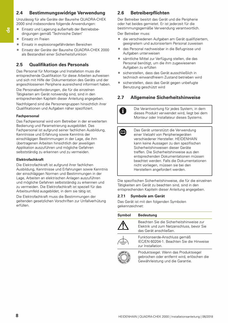
3.3.2 Accessories
Software options need to be enabled on the
product via a license key. Before you can use
the associated hardware components, you
need to enable the respective software option.
The following accessories are optionally available and can
be ordered from HEIDENHAIN:
Accessories Name ID
For installation
USB connecting cable 354770-xx
Adapter connector for TTL 1089210-01
2 Vpp adapter connector 1089216-01
Foot switch 681041-04
Adapter connector 11 µApp 1089213-01
Adapter connector 1 Vpp 1089214-01
Power cable 223775-01
For mounting
Multi-Pos holder 1089230-08
Duo-Pos stand 1089230-06
Multi-Pos stand 1089230-07
For OED software option
Optical fiber 681049-xx
Connection for optical fiber 681049-xx
Holder 681050-xx
3.4 In case of damage in transit
Have the shipping agent confirm the damage
Keep the packaging materials for inspection
Notify the sender of the damage
Contact the distributor or machine manufacturer for
replacement parts
If damage occurred during transit:
Keep the packaging materials for
inspection
Contact HEIDENHAIN or the machine
manufacturer
This applies also if damage occurred to
requested replacement parts during transit.
3.5 Repackaging and storage
Repackage and store the product carefully in accordance
with the conditions stated below.
3.5.1 Repackaging the product
Repackaging should correspond to the original packaging
as closely as possible.
Re-attach all mounting parts and dust protection
caps to the product as received from the factory, or
repackage them in the original packaging as received
from the factory
Repackage the product in such a way that
it is protected from impact and vibration during
transit
it is protected from the ingress of dust or humidity
Place all accessories that were included in the
shipment in the original packaging
Further information: "Items supplied and
accessories", Page 21
Enclose all the documentation that was included in the
original packaging
Further information: "Storage and distribution of the
documentation", Page 18
If the product is returned for repair to the
Service Department:
Ship the product without accessories,
without measuring devices and without
peripherals
3.5.2 Storage of the product
Package the product as described above
Observe the specified ambient conditions
Further information: "Specifications", Page 28
Inspect the product for damage after any transport or
longer storage times

en
HEIDENHAIN | QUADRA-CHEK 2000 | Installationsanleitung | 06/2018 23
4 Mounting
4.1 Overview
This chapter describes the mounting of the product. It
contains instructions about how to correctly mount the
product on stands or holders.
The following steps must be performed only
by qualified personnel.
Further information: "Personnel qualification",
Page 20
4.2 Assembly of the product
General mounting information
The mount for the mounting variants is provided on the
rear panel. The mounting hole pattern corresponds to a
grid of 50 mm x 50 mm.
Further information: "H", Page 175
The material for attachment of the mounting variants on
the device is included in delivery.
You will also need the following:
Torx T20 screwdriver
Torx T25 screwdriver
Allen key, size 2.5 (Duo-Pos stand)
Material for mounting on supporting surface
The unit must be mounted to a stand or a
holder to ensure the correct and intended use
of the product.
Mounting on Duo-Pos stand
You can attach the Duo-Pos stand to the product at a 20°
or 45° angle.
If you screw the Duo-Pos stand into the
product at a 45° angle, you must attach the
product at the upper end of the mounting
slots. Use a power cable cable with an angled
connector.
Use the provided M4 x 8 ISO 7380 hexagon socket
screws to fasten the stand to the lower threaded holes
on the rear panel
Comply with the permissible tightening
torque of 2.6 Nm
Using the mounting slots (width = 4.5 mm), screw the
stand to a supporting surface
or
Set up the device freely at the desired location
Route the cable from behind through the two supports
of the stand and then through the lateral openings to
the connections
Further information: "C", Page 4
Dimensions of the Duo-Pos stand
Further information: "J", Page 176
4.2.1 Mounting on Multi-Pos stand
Use the provided M4 x 8 ISO 14581 countersunk head
screws (black) to fasten the stand to the threaded
holes on the rear panel
Comply with the permissible tightening
torque of 2.6 Nm
Using two M5 screws, you can also optionally screw
the stand to a supporting surface from the bottom
Adjust the desired angle of inclination
To fix the stand: Tighten the T25 screw
Comply with the tightening torque for
screw T25
Recommended tightening torque:
5.0 Nm
Maximum permissible tightening
torque: 15.0 Nm
Route the cable from behind through the two supports
of the stand and then through the lateral openings to
the connections
Further information: "D", Page 4
Dimensions of the Multi-Pos stand
Further information: "K", Page 176

en
24 HEIDENHAIN | QUADRA-CHEK 2000 | Installationsanleitung | 06/2018
4.2.2 Mounting on Multi-Pos holder
Use the provided M4 x 8 ISO 14581 countersunk head
screws (black) to fasten the holder to the threaded
holes on the rear panel
Comply with the permissible tightening
torque of 2.6 Nm
Mount the holder with the supplied M8 screw, the
washers, the handle and the M8 hexagon nut to an
arm
Adjust the desired angle of inclination
To fix the holder: Tighten the T25 screw
Comply with the tightening torque for
screw T25
Recommended tightening torque:
5.0 Nm
Maximum permissible tightening
torque: 15.0 Nm
Route the cable from behind through the two supports
of the holder and then through the lateral openings to
the connections
Further information: "E", Page 4
Dimensions of the Multi-Pos holder
Further information: "L", Page 177
5 Installation
5.1 Overview
This chapter describes the Installation of the product. It
contains information about the product's connections and
instructions about how to correctly connect the peripheral
devices.
The following steps must be performed only
by qualified personnel.
Further information: "Personnel qualification",
Page 20
5.2 General information
NOTICE
Interference from sources of high electromagnetic
emission!
Peripheral devices, such as frequency inverters or servo
drives, may cause interference.
To increase the noise immunity to electromagnetic
influences:
Use the optional functional ground connection as
per IEC/EN 60204-1
Use only USB peripherals with continuous shielding,
e.g. by metalized film and metal braiding or a metal
housing. The degree of coverage provided by the
braiding must be 85 % or higher. The shield must
be connected around the entire circumference of
the connectors (360° connection).
NOTICE
Engaging and disengaging connecting elements!
Risk of damage to internal components.
Do not engage or disengage any connecting
elements while the unit is under power

en
HEIDENHAIN | QUADRA-CHEK 2000 | Installationsanleitung | 06/2018 25
NOTICE
Electrostatic discharge (ESD)!
This product contains electrostatic sensitive
components that can be destroyed by electrostatic
discharge (ESD).
It is essential to observe the safety precautions for
handling ESD-sensitive components
Never touch connector pins without ensuring proper
grounding
Wear a grounded ESD wristband when handling
product connections
NOTICE
Damage to the product due to incorrect wiring!
The incorrect wiring of inputs or outputs can cause
damage to the unit or to peripheral devices.
Keep the pin layouts and specifications of the unit in
mind.
Assign only pins or wires that will be used
Further information: "Specifications", Page 28
5.3 Product overview
The connections on the rear panel of the device are
protected by dust protection caps from contamination and
damage.
NOTICE
Contamination or damage may result if the dust
protection caps are missing!
If no dust protection caps are fitted to unused
connections, this may impair the proper functioning of
the contacts or destroy them.
Remove dust protection caps only when connecting
measuring devices or peripherals
If you remove a measuring device or peripheral, re-
attach the dust protection cap to the connection
The type of connections for encoders may
vary depending on the product version.
Rear panel without dust protection caps
Further information: "A", Page 4
Connections that are independent of software options:
2 X113: 15-pin D-sub connection, e.g. for foot switches
or touch probes
D-sub connections for encoders, 2 inputs enabled by
default, one other input can be enabled optionally
X1 to X3: Device variant with 15-pin D-sub connec-
tions for encoders with 1 VPP interface
X21 to X23: Device variant with 9-pin D-sub connec-
tions for encoders with a TTL interface
3
X1, X2, X21: Device variant with two 15-pin D-
sub connections for encoders with 1 VPP interface
and one 9-pin D-sub connection for encoders with
TTL interface
RJ45 Ethernet connection4
X116: Connection for communication and data
exchange with subsequent systems or PC
USB connection5
X32: USB 2.0 Hi-speed connection (type A) for print-
ers, input devices or USB mass storage devices
6 Functional ground connection as per IEC/EN 60204-1
7 X100: Power switch and power connection
8 Speaker
Connections that depend on software options:
Connections for optical edge detector for point
measurement
X107: reference input for optical waveguide from the
light source
1
X108: input for optical waveguide from the projection
screen

en
26 HEIDENHAIN | QUADRA-CHEK 2000 | Installationsanleitung | 06/2018
5.4 Connecting encoders
Remove and save the dust protection caps
Route the cables depending on the mounting variant
Further information: "Assembly of the product",
Page 23
Connect the encoder cables tightly to the respective
connections
Further information: "Product overview", Page 25
If the cable connectors include mounting screws, do
not overtighten them
Pin layout of X1, X2, X3
Further information: "1 VSS", Page 178
Pin layout of X21, X22, X23
Further information: "TTL", Page 178
5.5 Connecting an optical edge detector
Remove and save the dust protection caps
Route the fiber-optic cable depending on the mounting
variant
Further information: "Assembly of the product",
Page 23
Adhere to the manufacturer's
specifications regarding the maximum
bend radius of the fiber-optic cable
Connect the fiber-optic cable of the light source
(reference) to connection X107
Connect the fiber-optic cable from the projection
screen to connection X108
Further information: "Product overview", Page 25
Pin layout of X107, X108
Further information: "OED", Page 178
5.6 Wiring switching inputs and outputs
Depending on the peripherals to be
connected, the connection work may need to
be carried out by an electrical specialist.
Example: Safety Extra Low Voltage (SELV)
exceeded
Further information: "Personnel qualification",
Page 20
The encoder fulfills the requirements of
standard IEC 61010-1 only if the power to
the peripheral devices is supplied from a
secondary circuit with current limitation as per
IEC 61010-13rd Ed., Section 9.4 or with power
limitation as per IEC 60950-12nd Ed., Section
2.5 or from a Class 2 secondary circuit as
specified in UL1310.
In place of IEC 61010-13rd Ed., Section 9.4, the
corresponding sections of standards DIN EN
61010-1, EN 61010-1, UL 61010-1 and CAN/
CSA-C22.2 No. 61010-1 and, in place of IEC
60950-12nd Ed., Section 2.5, the corresponding
sections of standards DIN EN 60950-1, EN
60950-1, UL 60950-1, CAN/CSA-C22.2 No.
60950-1 can be applied.
Remove and save the dust protection caps
Route the cables depending on the mounting variant
Further information: "Assembly of the product", Page 23
Connect the connecting cables of the peripherals
tightly to their connectors
Further information: "Product overview", Page 25
If the cable connectors include mounting screws, do
not overtighten them
The digital or analog inputs and outputs must
be assigned in the device settings of the
respective switching function.
Pin layout of X 113
Further information: "X113", Page 179
5.7 Connecting a printer
Connecting a USB printer
Remove and save the dust protection caps
Route the cables depending on the mounting variant
Further information: "Assembly of the product",
Page 23
Connect USB printer to USB type A connection (X32).
Make sure the USB cable connector is fully inserted
Further information: "Product overview", Page 25
Pin layout X32
Further information: "USB", Page 178

en
HEIDENHAIN | QUADRA-CHEK 2000 | Installationsanleitung | 06/2018 27
Connecting an Ethernet printer
Remove and save the dust protection caps
Route the cables depending on the mounting variant
Further information: "Assembly of the product",
Page 23
Connect the Ethernet printer to the Ethernet port X116
using a standard CAT.5 cable. The cable connector
must firmly engage in the port
Further information: "Product overview", Page 25
Pin layout of X116
Further information: "RJ45", Page 179
5.8 Connecting a barcode scanner
The following barcode scanners can be
connected to the product:
COGNEX DataMan 8600 (with serial
module for USB)
Remove and save the dust protection caps
Route the cables depending on the mounting variant
Further information: "Assembly of the product",
Page 23
Connect barcode scanner to USB type A connection
(X32). Make sure the USB cable connector is fully
inserted
Further information: "Product overview", Page 25
Pin layout X32
Further information: "USB", Page 178
5.9 Connecting input devices
Remove and save the dust protection caps
Route the cables depending on the mounting variant
Further information: "Assembly of the product",
Page 23
Connect USB mouse or USB keyboard to USB type A
connection (X32). Make sure the USB cable connector
is fully inserted
Further information: "Product overview", Page 25
Pin layout X32
Further information: "USB", Page 178
5.10 Connecting a network peripheral
Remove and save the dust protection caps
Route the cables depending on the mounting variant
Further information: "Assembly of the product", Page 23
Connect the network peripheral to Ethernet port X116
using a standard CAT.5 cable. The cable connector
must firmly engage in the port
Further information: "Product overview", Page 25
Pin layout of X116
Further information: "RJ45", Page 179
5.11 Connecting the line voltage
WARNING
Risk of electric shock!
Improper grounding of electrical devices may result in
serious personal injury or death by electric shock.
Always use 3-wire power cables
Make sure the ground wire is correctly connected to
the ground of the building's electrical installations
WARNING
Fire hazard due to wrong power cable!
Use of a power cable that does not meet the
requirements of the mounting location may cause a fire
hazard.
Use only a power cable that meets at least the
national requirements of the respective country in
which the product is mounted
Use a power cable that meets the requirements to
connect the power connection to a 3-wire grounded
power outlet
Further information: "Product overview", Page 25
Pin layout X100
Further information: "X100", Page 178

en
28 HEIDENHAIN | QUADRA-CHEK 2000 | Installationsanleitung | 06/2018
6 Specifications
6.1 Overview
This chapter contains an overview of the product data
and drawings with the product dimensions and mating
dimensions.
6.2 Product data
Device
Housing Aluminum milled front + cast rear
panel
Housing
dimensions
200 mm x 169 mm x 41 mm
Fastener system,
mating dimen-
sions
Mounting hole pattern
50 mm x 50 mm
Display
Visual display unit LCD Widescreen (15:9)
color screen 17.8 cm (7")
800 x 480 pixels
Display step Selectable, min. 0.00001 mm
User interface User interface (GUI) with touch-
screen
Electrical data
Supply voltage AC 100 V ... 240 V (±10 %)
50 Hz ... 60 Hz (±5 %)
Input power max. 38 W
Buffer battery Lithium battery type CR2032; 3.0 V
Overvoltage
category
II
Number of
encoder inputs
2 (1 additional input can be
enabled via software option)
Encoder interfaces 11 μA: max. current 300 mA,
max. input frequency 150 kHz
1 VPP: max. current 300 mA,
max. input frequency 400 kHz
TTL: max. current 300 mA,
max. input frequency 5 MHz
Interpolation at
1 VPP
4096-fold
Touch probe
connection
Voltage supply DC 5 V or DC
12 V
5 V or floating switching output
4 digital inputs
1 digital output
Max. cable length with
HEIDENHAIN cable 30 m
Connection for
optical edge
detector
2 F-SMA sockets (screw thread
designation 1/4-36 UNS-2A)
Digital inputs TTL DC 0 V ... +5 V
Electrical data
Digital outputs TTL DC 0 V ... +5 V
Maximum load 1 kΩ
Data interface 1 USB 2.0 Hi-Speed (Type A),
maximum current 500 mA per
USB connection
1 Ethernet 10/100 Mbit/1 Gbit
(RJ45)
Environment
Operating
temperature
0 °C ... +45 °C
Storage
temperature
–20 °C ... +70 °C
Relative air
humidity
10 % ... 80 % RH, non-condensing
Altitude ≤ 2000 m
General information
Directives EMC Directive 2014/30/EU
Low Voltage Directive 2014/35/EU
RoHS Directive 2011/65/EU
Pollution degree 2
Protection
EN 60529
Front panel and side panels: IP 65
Rear panel: IP 40
Mass 1.3 kg
With Duo-Pos stand 1.45 kg
With Multi-Pos stand: 1.95 kg
With Multi-Pos holder: 1.65 kg
6.3 Product dimensions and mating
dimensions
Further information: Page 175 and the following
pages.
All dimensions in the drawings are in millimeters.

fr
HEIDENHAIN | QUADRA-CHEK 2000 | Installationsanleitung | 06/2018 29
1 Principes de base
1.1 Informations générales
Ce chapitre contient des informations relatives au produit
livré et à la documentation associée.
1.2 Informations sur le produit
Désignation du produit Numéro ID Index
QUADRA-CHEK 2000 1089180-xx ---
L'étiquette signalétique se trouve au dos de l'appareil.
Exemple :
2
3
1
1 Désignation du produit
2 Index
3 N° d'identification
1.3 Documentation du produit
1.3.1 Validité de la documentation
Avant d'utiliser cette documentation et l'appareil,
vous devez impérativement vous assurer que cette
documentation correspond bien à votre appareil.
Comparer le numéro d'identification et l'index indiqués
dans la documentation avec les informations figurant
sur l'étiquette signalétique de l'appareil.
Si les numéros d'identification et les index
correspondent, la documentation est applicable.
Si les numéros d'identification et les
index ne correspondent pas et que la
documentation n'est applicable, vous
trouverez la documentation actuelle de
l'appareil sous www.heidenhain.fr.
1.3.2 Comment lire la documentation
AVERTISSEMENT
Le non-respect de la documentation en vigueur
augmente le risque d'accidents à issue fatale, de
blessures et de dégâts matériels !
En ne respectant pas le contenu de la documentation,
vous vous exposez au risque d'accidents mortels, de
blessures ou de dégâts matériels.
Lire attentivement la documentation dans son
intégralité.
Conserver la documentation pour pouvoir la
consulter ultérieurement.
Le tableau suivant énumère les différents documents à
lire, dans leur ordre de priorité.
Documentation Description
Addendum Un addendum complète ou
remplace certains passages du
manuel d'utilisation et, éventuelle-
ment, du guide d'installation.
Si un addendum est compris dans la
livraison, c'est lui qui doit être lu en
priorité. Le reste de la documenta-
tion conserve sa validité.
Guide
d'installation
La guide d'installation contient
l’ensemble des informations et
des consignes de sécurité qui
permettent de monter et d'instal-
ler correctement l'appareil. Le guide
d'installation constitue un extrait
du manuel d'utilisation. Il est inclus
dans la livraison.
Le guide d'installation arrive en
deuxième position dans l’ordre des
priorités de lecture.
Manuel
d'utilisationi
Le manuel d'utilisation contient
toutes les informations et toutes
les remarques de sécurité qui
permettent d'utiliser l'appareil
de manière adéquate, conformé-
ment à sa destination. Le manuel
d’utilisation est disponible sur le
support de mémoire fourni et peut
également être téléchargé depuis
www.heidenhain.fr. Le manuel
d’utilisation doit impérativement
être lu avant la mise en service de
l’appareil.
Il arrive en troisième position dans
l’ordre des priorités de lecture.
Modifications souhaitées ou découverte d'une
"coquille"?
Nous nous efforçons en permanence d'améliorer notre
documentation. N'hésitez pas à nous faire part de vos
suggestions en nous écrivant à l'adresse e-mail suivante :

fr
30 HEIDENHAIN | QUADRA-CHEK 2000 | Installationsanleitung | 06/2018
1.3.3 Conservation et transfert de la
documentation
Le mode d’emploi doit être conservé à proximité
immédiate du poste de travail et être maintenu en
permanence à la disposition de l'ensemble du personnel.
L'exploitant doit informer son personnel de l'endroit où
est conservé le mode d’emploi. Au cas où celui-ci serait
devenu illisible, l'exploitant est tenu de s'en procurer un
nouvel exemplaire auprès du fabricant.
Si l'appareil est remis ou vendu à un tiers, il est impératif
de remettre au nouveau propriétaire les documents
suivants :
l'addendum (si fourni)
le manuel d'utilisation
1.4 A propos de ce manuel
Ce manuel comprend toutes les informations et toutes
les consignes de sécurité qui permettent de monter et
d'installer correctement l'appareil.
1.4.1 Type de document
Guide d'installation
Le présent document est un guide d'installation du
produit.
Le guide d'installation
constitue un extrait du manuel d'utilisation du produit
suit le produit pendant tout son cycle de vie
contient toutes les informations et toutes les
consignes de sécurité nécessaires au montage et à
l’installation conformes du produit
ne contient aucune information en dehors de celles
relatives à l’installation du produit, telles que la mise
en service ou le fonctionnement du produit
1.4.2 Groupes ciblés par ce manuel
Le contenu de ce manuel doit être lu et observé par toute
personne qui se voit confier l'une des tâches suivantes :
montage
installation
1.4.3 Types de remarques utilisés
Remarques sur la sécurité
Les consignes de sécurité ont pour but de mettre en
garde l'utilisateur devant les risques liés à la manipulation
de l'appareil et indiquent comment les éviter. Les
différentes consignes de sécurité sont classées par ordre
de gravité du danger et sont réparties comme suit :
DANGER
Danger signale l'existence d'un risque pour les
personnes. Si vous ne suivez pas la procédure
qui permet d'éviter le risque existant, le danger
occasionnera certainement des blessures graves,
voire mortelles.
AVERTISSEMENT
Avertissement signale l'existence d'un risque pour
les personnes. Si vous ne suivez pas la procédure qui
permet d'éviter le risque existant, le danger pourrait
occasionner des blessures graves, voire mortelles.
ATTENTION
Attention signale l'existence d'un risque pour les
personnes. Si vous ne suivez pas la procédure qui
permet d'éviter le risque existant, le danger pourrait
occasionner de légères blessures.
REMARQUE
Remarque signale l'existence d'un risque pour
les objets ou les données. Si vous ne suivez pas la
procédure qui permet d'éviter le risque existant, le
danger pourrait occasionner un dégât matériel.
Notes d'information
Les notes d'information garantissent un fonctionnement
sûr et efficace de l'appareil. Les notes d’information sont
réparties comme suit :
Ce symbole signale une astuce.
Une astuce vous fournit des informations
supplémentaires ou complémentaires.
Le symbole représentant une roue dentée
signale que la fonction décrite dépend de la
machine, par ex. :
Votre machine doit être équipée de l'option
de logiciel ou du hardware nécessaire.
Le comportement des fonctions dépend
des paramètres configurables sur la
machine.
Le symbole représentant un livre correspond à
un renvoi à une documentation externe, p. ex.
à la documentation du constructeur de votre
machine ou d'un autre fournisseur.

fr
HEIDENHAIN | QUADRA-CHEK 2000 | Installationsanleitung | 06/2018 31
1.4.4 Eléments typographiques
Les éléments typographiques suivants sont utilisés dans
ce manuel :
Représentation Signification
...
...
caractérise/remplace une action et le
résultat d'une action
Exemple :
Appuyer sur OKLa boîte de dialogue contenant le
message se ferme.
...
...
caractérise/remplace une énumération
Exemple :
interface TTL
interface EnDat
...
Gras permet d'identifier des menus, des
affichages et des boutons
Exemple :
Appuyer sur EteindreLe système d'exploitation se
ferme.
Mettre l'appareil hors tension en
utilisant l'interrupteur d'alimenta-
tion
2 Sécurité
2.1 Informations générales
Ce chapitre contient des informations de sécurité
importantes pour monter et installer correctement
l'appareil.
2.2 Mesures de sécurité préventives
d'ordre général
Les consignes de sécurité applicables pour l'utilisation du
système sont les consignes de sécurité généralement
reconnues, particulièrement celles qui sont reconnues
dans le cadre d'une utilisation avec des appareils sous
tension. Le non-respect de ces consignes de sécurité
peut endommager l'appareil ou provoquer des blessures.
Les consignes de sécurité peuvent varier d'une entreprise
à l'autre. En cas de divergence entre le contenu de
ce manuel et les consignes internes de l'entreprise
utilisant cet appareil, ce sont les instructions les plus
contraignantes qui doivent être observées.
2.3 Utilisation conforme à la destination
Les appareils de la série QUADRA-CHEK 2000 sont des
électroniques d'exploitation numériques haut de gamme
qui permettent d'acquérir des éléments de contour 2D
dans des applications de métrologie. Ces appareils sont
principalement utilisés sur des machines de mesure et
des projecteurs de profil.
Les appareils de cette série
ne peuvent être mis en œuvre que dans des
applications industrielles, dans un environnement
industriel
doivent être montés sur un socle ou un support pour
une utilisation conforme
sont prévus pour une utilisation en intérieur et dans
un environnement exempt d'humidité, de salissures,
d'huile et de lubrifiants, conformément aux spéci-
fications techniques
Ces appareils supportent plusieurs appareils
périphériques de différents fabricants.
HEIDENHAIN ne peut se prononcer sur la
conformité d'utilisation de ces appareils.
Les informations relatives à la conformité
d'utilisation qui sont contenues dans la
documentation de l'appareil concerné doivent
impérativement être respectées.

fr
32 HEIDENHAIN | QUADRA-CHEK 2000 | Installationsanleitung | 06/2018
2.4 Utilisation non conforme à la
destination
Les applications suivantes sont notamment proscrites
pour tous les appareils de la série QUADRA-CHEK 2000 :
Utilisation et stockage en dehors des conditions
spécifiées dans "Caractéristiques techniques"
Utilisation à l'air libre
Utilisation dans des zones explosibles
Utilisation des appareils de la série QUADRA-CHEK
2000 comme composante d'une fonction de sécurité
2.5 Qualification du personnel
Le personnel en charge du montage et de l'installation
doit être qualifié pour effectuer ces travaux et s'être
suffisamment informé en lisant la documentation relative
à l'appareil et aux périphériques connectés.
Les différents chapitres de ce manuel présentent les
exigences que le personnel doit satisfaire dans le cadre
de ces opérations.
Les différents types de personnes énumérées ci-après
sont classés selon leurs qualifications et les tâches qui
leur incombent.
Personnel spécialisé
Le personnel spécialisé est formé par l'exploitant
pour utiliser et paramétrer l'appareil de manière plus
vaste. Etant donné sa qualification professionnelle, ses
connaissances, son expérience et sa connaissance des
consignes en vigueur, le personnel spécialisé est en
mesure d'effectuer les tâches qui lui incombent, ainsi que
de détecter et d'éviter les risques éventuels.
Electricien
Etant donné sa qualification professionnelle, ses
connaissances, son expérience et sa connaissance des
normes, l'électricien est en mesure de travailler sur les
installations électriques, ainsi que de détecter et d'éviter
les risques éventuels. L'électricien est spécialement
formé pour l'environnement de travail dans lequel il
intervient.
Il doit satisfaire aux exigences des dispositions légales en
matière de prévention des accidents.
2.6 Obligations de l'exploitant
L'exploitant est propriétaire de l'appareil et des
périphériques ou bien a loué les deux. Il est tenu de
s'assurer que l'appareil et les périphériques sont utilisés
conformément à leur destination.
L'exploitant doit impérativement :
confier les différentes tâches à effectuer sur l'appareil
à un personnel qualifié, compétent et habilité
informer le personnel des compétences et des tâches
qui lui incombent, et être à même de fournir la preuve
d'avoir rempli cette obligation
mettre tout l'équipement nécessaire à la disposition du
personnel, afin qu'il puisse accomplir les tâches qui lui
incombent
s'assurer que l'appareil est exclusivement utilisé
dans des conditions irréprochables d'un point de vue
technique
s'assurer que l'appareil est protégé de toute utilisation
non autorisée
2.7 Consignes de sécurité générales
C'est le monteur ou l'installateur du système
qui est responsable du système dans lequel
est utilisé ce produit.
L'appareil supporte l'utilisation de plusieurs
appareils périphériques de différents
fabricants. HEIDENHAIN ne peut se
prononcer sur les consignes de sécurité
spécifiques à ces appareils. Il est impératif de
respecter les consignes de sécurité figurant
dans les documentations afférentes. Si la
documentation n’est pas disponible, vous
devez vous la procurer auprès du fabricant.
Les consignes de sécurité propres à chaque tâche
sur l'appareil sont indiquées dans les chapitres
correspondants de ce manuel.
2.7.1 Symboles sur l'appareil
L'appareil présente les symboles suivants :
Symbole Signification
Avant de connecter l'appareil, respecter les
instructions de sécurité relatives à l´équipe-
ment électrique et au raccordement au
réseau.
Prise de mise à la terre, conformément à
la norme CEI/EN 60204-1. Respecter les
instructions d'installation.
Etiquette de garantie. La garantie du produit
est caduque si l'étiquette de garantie du
produit est déchirée ou si elle a été retirée.

fr
HEIDENHAIN | QUADRA-CHEK 2000 | Installationsanleitung | 06/2018 33
2.7.2 Consignes de sécurité relatives à
l'installation électrique
AVERTISSEMENT
Il est dangereux de toucher les pièces conductrices
de tension en ouvrant l'appareil.
Un risque de décharge électrique, de brûlure ou de
blessure mortelle peut survenir.
Ne jamais ouvrir le boîtier
Laisser le fabricant intervenir
AVERTISSEMENT
Danger d'électrocution en cas de contact direct ou
indirect avec les pièces conductrices de tension
Un risque de décharge électrique, de brûlure ou de
blessure mortelle peut survenir.
Seul un personnel spécialement formé est habilité à
effectuer des travaux sur l'installation électrique ou
sur les composants conducteurs de courant.
Utiliser exclusivement des connecteurs et
des câbles conformes aux normes pour les
raccordements au réseau et toutes les connexions
d'interfaces
Faire immédiatement remplacer les composants
électriques défectueux par le fabricant
Contrôler régulièrement tous les câbles raccordés
et tous les ports de l'appareil. Remédier
immédiatement aux défauts, tels que les liaisons
desserrées ou les câbles fondus
REMARQUE
Détérioration des composants internes de
l'appareil !
Toute ouverture de l'appareil rend la garantie et la
responsabilité du fabricant caduque.
Ne jamais ouvrir le boîtier
Laisser le fabricant intervenir
3 Transport et stockage
3.1 Vue d'ensemble
Ce chapitre contient des informations relatives au
transport et au stockage, au contenu de la livraison et aux
accessoires de l'appareil.
Seul un personnel qualifié est habilité à
effectuer les opérations suivantes :
Informations complémentaires :
"Qualification du personnel", Page 32
3.2 Déballage de l'appareil
Ouvrir le carton d'emballage par le haut
Retirer le matériau d'emballage
Sortir le contenu
Vérifier que le contenu de la livraison est complet
Vérifier que la livraison n'a pas été endommagée
pendant le transport
3.3 Contenu de la livraison et
accessoires
3.3.1 Contenu de la livraison
La livraison contient les articles suivants :
Désignation Description
Pièce de démo 2D
Appareil
Manuel d'utilisation
Guide d'installation
Addendum (optionnel)

fr
34 HEIDENHAIN | QUADRA-CHEK 2000 | Installationsanleitung | 06/2018
3.3.2 Accessoires
Les options logicielles doivent être activées en
entrant une clé de licence sur l’appareil. Les
composants hardware associés ne peuvent
être utilisés qu’une fois l’option logicielle
concernée activée.
Les accessoires listés ci-après peuvent être commandés
en option auprès de HEIDENHAIN :
Acces-
soires
Désignation ID
Pour l'installation
Adaptateur 11 µAcc 1089213-01
Adaptateur 1 Vcc 1089214-01
Câble secteur 223775-01
Adaptateur 2 Vcc 1089216-01
Commutateur à pédale 681041-04
Câble de liaison USB 354770-xx
Adaptateur TTL 1089210-01
Pour le montage
Support Multi-Pos 1089230-08
Socle Duo-Pos 1089230-06
Socle Multi-Pos 1089230-07
De l'option logicielle OED
Câble à fibre optique 681049-xx
Liaison par câble à fibre
optique
681049-xx
Support 681050-xx
3.4 En cas d'avarie
Faire constater l'avarie par le transporteur
Conserver les emballages pour les besoins de
l'enquête
Signaler l'avarie au transporteur
Pour les pièces de rechange, contacter le distributeur
ou le constructeur de la machine
En cas de dommage pendant le transport :
Conserver les emballages pour les besoins
de l'enquête
Contacter HEIDENHAIN ou le constructeur
de la machine.
Ceci vaut également pour les demandes de
pièces de rechange.
3.5 Reconditionnement et stockage
L'appareil doit être conditionné et stocké avec précaution,
selon les conditions mentionnées ci-après.
3.5.1 Emballage de l'appareil
Le reconditionnement doit être le plus conforme possible
à l'emballage d'origine.
Tous les composants et capuchons anti-poussière
doivent être en place sur l'appareil, ou emballés, selon
leur état à la livraison.
Emballer l'appareil de telle manière que :
les chocs et les secousses sont amortis pendant le
transport
l'humidité et la poussière ne pénètrent pas à
l'intérieur
Placer toutes les pièces accessoires dans l'emballage
Informations complémentaires : "Contenu de la
livraison et accessoires", Page 33
Joindre l'ensemble de la documentation fournie à la
livraison
Informations complémentaires : "Conservation et
transfert de la documentation", Page 30
En cas de retour de l'appareil au service après-
vente pour réparation :
Expédier l'appareil sans accessoire,
sans système de mesure ni appareil
périphérique
3.5.2 Stockage de l’appareil
Emballer l'appareil comme décrit ci-dessus
Respecter les règles relatives aux conditions
ambiantes
Informations complémentaires : "Caractéristiques
techniques", Page 40
Vérifier après chaque transport et après toute période
de stockage prolongée que l'appareil n'est pas
endommagé
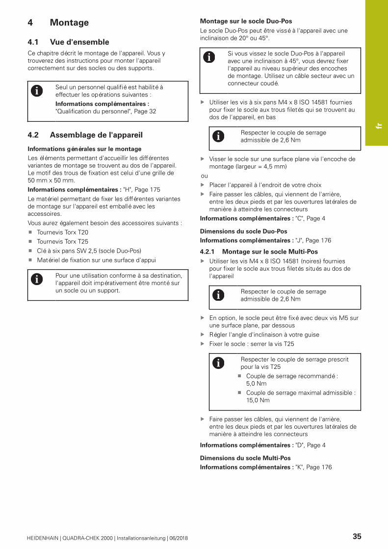
fr
HEIDENHAIN | QUADRA-CHEK 2000 | Installationsanleitung | 06/2018 35
4 Montage
4.1 Vue d'ensemble
Ce chapitre décrit le montage de l'appareil. Vous y
trouverez des instructions pour monter l'appareil
correctement sur des socles ou des supports.
Seul un personnel qualifié est habilité à
effectuer les opérations suivantes :
Informations complémentaires :
"Qualification du personnel", Page 32
4.2 Assemblage de l'appareil
Informations générales sur le montage
Les éléments permettant d'accueillir les différentes
variantes de montage se trouvent au dos de l'appareil.
Le motif des trous de fixation est celui d'une grille de
50 mm x 50 mm.
Informations complémentaires : "H", Page 175
Le matériel permettant de fixer les différentes variantes
de montage sur l'appareil est emballé avec les
accessoires.
Vous aurez également besoin des accessoires suivants :
Tournevis Torx T20
Tournevis Torx T25
Clé à six pans SW 2,5 (socle Duo-Pos)
Matériel de fixation sur une surface d'appui
Pour une utilisation conforme à sa destination,
l'appareil doit impérativement être monté sur
un socle ou un support.
Montage sur le socle Duo-Pos
Le socle Duo-Pos peut être vissé à l'appareil avec une
inclinaison de 20° ou 45°.
Si vous vissez le socle Duo-Pos à l'appareil
avec une inclinaison à 45°, vous devrez fixer
l'appareil au niveau supérieur des encoches
de montage. Utilisez un câble secteur avec un
connecteur coudé.
Utiliser les vis à six pans M4 x 8 ISO 14581 fournies
pour fixer le socle aux trous filetés qui se trouvent au
dos de l'appareil, en bas
Respecter le couple de serrage
admissible de 2,6 Nm
Visser le socle sur une surface plane via l'encoche de
montage (largeur = 4,5 mm)
ou
Placer l'appareil à l'endroit de votre choix
Faire passer les câbles, qui viennent de l'arrière,
entre les deux pieds et par les ouvertures latérales de
manière à atteindre les connecteurs
Informations complémentaires : "C", Page 4
Dimensions du socle Duo-Pos
Informations complémentaires : "J", Page 176
4.2.1 Montage sur le socle Multi-Pos
Utiliser les vis M4 x 8 ISO 14581 (noires) fournies
pour fixer le socle aux trous filetés situés au dos de
l'appareil
Respecter le couple de serrage
admissible de 2,6 Nm
En option, le socle peut être fixé avec deux vis M5 sur
une surface plane, par dessous
Régler l'angle d'inclinaison à votre guise
Fixer le socle : serrer la vis T25
Respecter le couple de serrage prescrit
pour la vis T25
Couple de serrage recommandé :
5,0 Nm
Couple de serrage maximal admissible :
15,0 Nm
Faire passer les câbles, qui viennent de l'arrière,
entre les deux pieds et par les ouvertures latérales de
manière à atteindre les connecteurs
Informations complémentaires : "D", Page 4
Dimensions du socle Multi-Pos
Informations complémentaires : "K", Page 176

fr
36 HEIDENHAIN | QUADRA-CHEK 2000 | Installationsanleitung | 06/2018
4.2.2 Montage sur le support Multi-Pos
Utiliser les vis M4 x 8 ISO 14581 (noires) fournies
pour fixer le support aux trous filetés situés au dos de
l'appareil
Respecter le couple de serrage
admissible de 2,6 Nm
Utiliser la vis M8 fournie, la poignée et
l'écrou M8 à six pans pour monter le support sur un
bras
Régler l'angle d'inclinaison à votre guise
Fixer le support : serrer la vis T25
Respecter le couple de serrage prescrit
pour la vis T25
Couple de serrage recommandé :
5,0 Nm
Couple de serrage maximal admissible :
15,0 Nm
Faire passer les câbles, qui viennent de l'arrière,
entre les deux pieds du support et par les ouvertures
latérales de manière à atteindre les connecteurs
Informations complémentaires : "E", Page 4
Dimensions du support Multi-Pos
Informations complémentaires : "L", Page 177
5 Installation
5.1 Vue d'ensemble
Ce chapitre décrit l'installation de l'appareil. Vous y
trouverez des informations sur les connecteurs de
l'appareil et des instructions sur la manière de raccorder
correctement des appareils périphériques.
Seul un personnel qualifié est habilité à
effectuer les opérations suivantes :
Informations complémentaires :
"Qualification du personnel", Page 32
5.2 Informations générales
REMARQUE
Perturbations causées par des sources d'émissions
hautement électromagnétiques !
Les appareils périphériques tels que les variateurs de
fréquence ou les moteurs d'entraînement peuvent être
à l'origine de perturbations.
Pour augmenter la résistance aux perturbations
électromagnétiques :
Utiliser une prise de terre fonctionnelle optionnelle
selon la norme CEI/EN 60204-1
Utiliser exclusivement des appareils périphériques
USB entièrement blindés, par exemple à l'aide
d'un film métallique et d'une tresse ou d'un boîtier
métallique. Le taux de couverture de la tresse de
blindage doit être de 85 % ou plus. Le blindage doit
être complètement relié à la prise (liaison à 360°).
REMARQUE
Brancher et débrancher les connecteurs !
Risque d'endommagement des composants internes
Ne brancher ou débrancher les connecteurs que si
l'appareil est hors tension

fr
HEIDENHAIN | QUADRA-CHEK 2000 | Installationsanleitung | 06/2018 37
REMARQUE
Décharge électrostatique (DES)
Cet appareil contient des composants qui peuvent être
détruits par une décharge électrostatique (DES).
Respecter impérativement les consignes de
sécurité lors de la manipulation de composants
sensibles aux décharges électrostatiques
Ne jamais toucher les plots sans mise à la terre
appropriée
Porter un bracelet antistatique pour les
interventions sur les prises de l'appareil
REMARQUE
Risque d'endommager l'appareil si le câblage est
incorrect !
Un mauvais câblage des entrées ou des sorties est
susceptible d'endommager l'appareil ou les appareils
périphériques.
Respecter l'affectation des broches et les
spécifications techniques de l'appareil
Seuls les plots/fils utilisés doivent être reliés.
Informations complémentaires : "Caractéristiques
techniques", Page 40
5.3 Vue d'ensemble de l’appareil
Les ports situés au dos de l'appareil sont protégés des
salissures et du risque de dommages par des capuchons
anti-poussière.
REMARQUE
Salissure et détérioration en cas d'absence de
capuchons anti-poussière !
Les contacts de connexion risquent de ne pas
fonctionner correctement si vous ne placez pas de
capuchon anti-poussière sur les ports qui ne sont pas
utilisés.
Ne retirer les capuchons anti-poussière que pour
connecter des appareils de mesure ou des appareils
périphériques
Remettre le capuchon anti-poussière en place
dès que les systèmes de mesure ou les appareils
périphériques sont débranchés
Le type de ports pour systèmes de mesure
peut varier en fonction de la version de
l’appareil.
Dos de l'appareil sans capuchons anti-poussière
Informations complémentaires : "A", Page 4
Ports indépendants des options logicielles :
2 X113 : port Sub-D 15 plots, par ex. pour commuta-
teurs à pédale, palpeurs
Ports Sub-D pour systèmes de mesure ; 2 entrées
activées par défaut et 1 entrée supplémentaire
activable en option
X1-X3 : variante d'appareil avec ports Sub-D 15 plots
pour systèmes de mesure avec interface1 VCC
X21-X23 : variante d'appareil avec ports Sub-D
9 plots pour systèmes de mesure à interface TTL
3
X1, X2, X21 : variante d'appareil avec deux ports
Sub-D 15 plots pour systèmes de mesure à inter-
face 1 VCC et un port Sub-D 9 plots pour systèmes de
mesure à interface TTL
Port Ethernet RJ454
X116 : port pour la communication et l'échange de
données avec les systèmes consécutifs ou le PC.
Prise USB5
X32 : port USB 2.0 Hi-Speed (type A) pour impri-
mante, appareil de saisie ou support de stockage de
masse USB
6 Prise de mise à la terre selon la norme CEI/
EN 60204-1
7 X100 : interrupteur d'alimentation et raccordement
secteur
8 Haut-parleur
Ports dépendants des options logicielles :
Ports pour détecteur d'arête optique permettant d'ac-
quérir les points de mesure
1
X107 : entrée de référence pour le câble à fibre
optique de la source lumineuse entrante
fr
38 HEIDENHAIN | QUADRA-CHEK 2000 | Installationsanleitung | 06/2018
X108 : entrée pour le câble à fibre optique de l'écran
de projection entrant
5.4 Connexion des systèmes de mesure
Retirer et conserver les caches anti-poussière
Poser les câbles comme prescrit selon la variante de
montage
Informations complémentaires : "Assemblage de
l'appareil", Page 35
Raccorder complètement les systèmes de mesure aux
connecteurs correspondants
Informations complémentaires : "Vue d'ensemble de
l’appareil", Page 37
Ne pas trop serrer les vis des connecteurs à vis
Brochage des ports X1, X2, X3
Informations complémentaires : "1 VSS", Page 178
Brochage des ports X21, X22, X23
Informations complémentaires : "TTL", Page 178
5.5 Connexion d'un détecteur d'arête
optique
Retirer et conserver les caches anti-poussière
Placer les câbles à fibre optique comme prescrit selon
la variante de montage
Informations complémentaires : "Assemblage de
l'appareil", Page 35
Respecter les informations du
constructeur concernant le rayon
maximal de courbure des câbles à fibre
optique.
Connecter le câble à fibre optique de la source
lumineuse (référence) au port X107.
Connecter le câble à fibre optique de l'écran de
projection en entrée au port X108.
Informations complémentaires : "Vue d'ensemble de
l’appareil", Page 37
Brochage des ports X107, X108
Informations complémentaires : "OED", Page 178
5.6 Câbler les entrées et sorties à
commutation
Selon les appareils périphériques à raccorder,
il peut être nécessaire de faire appel à un
électricien spécialisé pour les opérations de
connexion.
Exemple : dépassement du seuil de basse
tension de sécurité (SELV)
Informations complémentaires :
"Qualification du personnel", Page 32
L'appareil n'est conforme aux exigences de
la norme CEI 61010-1 que si les appareils
périphériques sont alimentés par un circuit
secondaire à énergie limitée selon la
norme CEI 61010-13e éd., paragraphe 9.4,
ou à puissance limitée selon la norme
CEI 60950-12e éd., paragraphe 2.5, ou par un
circuit secondaire homologué Classe 2 d'après
la norme UL1310.
À la place de la norme CEI 61010-13e éd.,
paragraphe 9.4, il est possible d’appliquer
les paragraphes correspondants des normes
DIN EN 61010-1, EN 61010-1, UL 61010-1 et
CAN/CSA-C22.2 No 61010-1 ou à la place de la
norme CEI 60950-12e éd., paragraphe 2.5, les
paragraphes correspondants des normes DIN
EN 60950-1, EN 60950-1, UL 60950-1, CAN/
CSA-C22.2 No 60950-1.
Retirer et conserver les capuchons anti-poussière
Poser les câbles comme prescrit selon la variante de
montage
Informations complémentaires : "Assemblage de
l'appareil", Page 35
Raccorder les câbles de liaison des appareils
périphériques à leur port correspondant
Informations complémentaires : "Vue d'ensemble de
l’appareil", Page 37
Pour les connecteurs avec vis : ne pas serrer
complètement les vis
Les entrées et sorties numériques ou
analogiques doivent être affectées à la
fonction de commutation correspondante dans
les paramètres de l'appareil.
Brochage du port X 113
Informations complémentaires : "X113", Page 179

fr
HEIDENHAIN | QUADRA-CHEK 2000 | Installationsanleitung | 06/2018 39
5.7 Raccorder une imprimante
Brancher une imprimante USB
Retirer et conserver les capuchons anti-poussière
Poser les câbles comme prescrit selon la variante de
montage
Informations complémentaires : "Assemblage de
l'appareil", Page 35
Raccorder une imprimante USB au port USB de
type A (X32). Le connecteur du câble USB doit être
complètement inséré.
Informations complémentaires : "Vue d'ensemble de
l’appareil", Page 37
Brochage des ports X32
Informations complémentaires : "USB", Page 178
Brancher une imprimante Ethernet
Retirer et conserver les capuchons anti-poussière
Poser les câbles comme prescrit selon la variante de
montage
Informations complémentaires : "Assemblage de
l'appareil", Page 35
Pour raccorder une imprimante Ethernet au port
Ethernet X116, utiliser un câble CAT.5 disponible dans
le commerce. S'assurer que le connecteur du câble
est bien inséré dans la prise.
Informations complémentaires : "Vue d'ensemble de
l’appareil", Page 37
Brochage du port X116
Informations complémentaires : "RJ45", Page 179
5.8 Raccorder un lecteur de code-barres
Les lecteurs de codes-barres suivants peuvent
être raccordés à l'appareil :
COGNEX DataMan 8600 (avec module
série pour USB)
Retirer et conserver les caches anti-poussière
Placer les câbles comme prescrit selon la variante de
montage
Informations complémentaires : "Assemblage de
l'appareil", Page 35
Raccorder le lecteur de code-barres au port USB de
type A (X32). Le connecteur du câble USB doit être
complètement inséré.
Informations complémentaires : "Vue d'ensemble de
l’appareil", Page 37
Brochage des ports , X32
Informations complémentaires : "USB", Page 178
5.9 Raccorder des appareils de saisie
Retirer et conserver les capuchons anti-poussière
Placer les câbles comme prescrit selon la variante de
montage
Informations complémentaires : "Assemblage de
l'appareil", Page 35
Raccorder une souris USB ou un clavier USB au port
USB de type A (X32). Le connecteur du câble USB doit
être complètement inséré.
Informations complémentaires : "Vue d'ensemble de
l’appareil", Page 37
Brochage des ports X32
Informations complémentaires : "USB", Page 178

fr
40 HEIDENHAIN | QUADRA-CHEK 2000 | Installationsanleitung | 06/2018
5.10 Connexion d'un périphérique réseau
Retirer et conserver les caches anti-poussière
Poser les câbles comme prescrit selon la variante de
montage
Informations complémentaires : "Assemblage de
l'appareil", Page 35
Pour raccorder un périphérique réseau au port
Ethernet X116, utiliser un câble CAT.5 disponible dans
le commerce. Insérer complètement le connecteur du
câble dans la prise.
Informations complémentaires : "Vue d'ensemble de
l’appareil", Page 37
Brochage du port X116
Informations complémentaires : "RJ45", Page 179
5.11 Raccorder l'alimentation en tension
AVERTISSEMENT
Risque de décharge électrique !
Les appareils dont la mise à la terre n'est pas
appropriée peuvent provoquer des blessures graves,
voire mortelles, suite à une décharge électrique.
D'une manière générale, utiliser un câble secteur à
3 plots.
Vérifier que le conducteur de mise à la terre est
correctement raccordé à l'installation du bâtiment.
AVERTISSEMENT
Risque d'incendie en cas d'utilisation d'un câble
secteur non adapté !
Risque d'incendie en cas d'utilisation d'un câble
secteur non conforme aux exigences requises sur le
lieu d'installation.
Utiliser exclusivement un câble secteur qui est
au minimum conforme aux exigences nationales
requises sur le lieu d'installation
Brancher la fiche secteur avec un câble d'alimentation
conforme aux exigences dans la prise secteur avec
conducteur de mise à la terre
Informations complémentaires : "Vue d'ensemble de
l’appareil", Page 37
Affectation des broches du plot X100
Informations complémentaires : "X100", Page 178
6 Caractéristiques techniques
6.1 Vue d'ensemble
Ce chapitre contient un récapitulatif des données de
l'appareil et des schémas sur lesquels figures les
dimensions de l'appareil et les cotes d'encombrement.
6.2 Données de l'appareil
Appareil
Carter Face avant fraisée en aluminium +
face arrière en fonte
Dimensions du
carter
200 mm x 169 mm x 41 mm
Type de fixation,
dimensions
Motif des trous de fixation
50 mm x 50 mm
Affichage
Ecran Écran large LCD (15:9)
Écran couleur 17,8 cm (7")
800 x 480 pixels
Résolution
d'affichage
réglable, 0,00001 mm min.
Interface
utilisateur
Interface utilisateur (GUI) avec
écran tactile (Touchscreen)
Caractéristiques électriques
Tension d'alimen-
tation
100 V ... 240 V CA (±10 %)
50 Hz ... 60 Hz (±5 %)
Puissance d'entrée max. 38 W
Batterie-tampon Pile au lithium de type CR2032 ;
3,0 V
Catégorie de
surtension
II
Nombre d'entrées
pour syst.de mes.
2 (1 entrée supplémentaire
activable par option logicielle)
Interfaces
de systèmes
de mesure
11 μA : courant
maximal 300 mA,
Fréquence d'entrée max. 150 kHz
1 VCC : courant max. 300 mA,
fréquence d'entrée max. 400 kHz
TTL : courant max. 300 mA,
fréquence d'entrée max. 5 MHz
Interpolation pour
1 VCC
4096 fois
Port pour palpeur Alimentation en tension 5 V CC
ou 12 V CC
Sortie de commutation 5 V ou
libre de potentiel
4 entrées numériques
1 sortie numérique
Longueur de câble max. avec
un câble HEIDENHAIN 30 m
Port pour détec-
teur d'arête
optique
2 prises femelles F-SMA (désigna-
tion de filetage 1/4-36 UNS-2A)

fr
HEIDENHAIN | QUADRA-CHEK 2000 | Installationsanleitung | 06/2018 41
Caractéristiques électriques
Entrées
numériques
TTL 0 V CC ... +5 V
Sorties
numériques
TTL 0 V CC ... +5 V
Charge maximale 1 kΩ
Interface de
données
1 USB 2.0 Hi-Speed (type A),
courant maximal 500 mA par
port USB
1 Ethernet 10/100 Mbits/1 Gbit
(RJ45)
Environnement
Température de
service
0°C ... +45 °C
Température de
stockage
-20 °C ... +70 °C
Humidité relative 10 % ... 80 % sans condensation
Hauteur ≤ 2000 m
Généralités
Directives Directive CEM 2014/30/UE
Directive basse tension
2014/35/UE
Directive RoHS* 2011/65/
UE (directive sur la limitation
de l’utilisation de certaines
substances dangereuses dans
les équipements électriques et
électroniques)
Degré de salissure 2
Indice de protec-
tion EN 60529
Face avant et faces latérales: IP65
Face arrière : IP40
Masse 1,3 kg
avec socle Duo-Pos : 1,45 kg
avec socle Multi-Pos : 1,95 kg
avec support Multi-Pos : 1,65 kg
6.3 Dimensions de l'appareil et cotes
d'encombrement
Pour plus d'informations : Page 175 et les pages
suivantes.
Toutes les cotes des dessins sont indiquées en
millimètres.

it
42 HEIDENHAIN | QUADRA-CHEK 2000 | Installationsanleitung | 06/2018
1 Informazioni basilari
1.1 Panoramica
Questo capitolo contiene informazioni sul presente
prodotto e sul presente manuale.
1.2 Informazioni sul prodotto
Denominazione prodotto ID Indice
QUADRA-CHEK 2000 1089180-xx ---
La targhetta di identificazione è collocata sul retro
dell'apparecchiatura.
Esempio
2
3
1
1 Denominazione prodotto
2 Indice
3 Numero di identificazione (ID)
1.3 Documentazione sul prodotto
1.3.1 Validità della documentazione
Prima dell’utilizzo è necessario verificare che la versione
della documentazione e quella dell'apparecchiatura
corrispondano.
Verificare la corrispondenza tra il numero identificativo
indicato nella documentazione e l'indice con i dati sulla
targhetta di identificazione dell'apparecchiatura
La documentazione è da ritenersi valida se i numeri
identificativi e gli indici corrispondono
Se i numeri identificativi e gli indici non
corrispondono e la documentazione
risulta pertanto non valida, ricercare
la documentazione aggiornata
dell'apparecchiatura all'indirizzo
www.heidenhain.it.
1.3.2 Indicazioni sulla lettura della
documentazione
ALLARME
Incidenti con conseguenze letali, lesioni o danni
materiali in caso di mancata osservanza della
documentazione!
Se non ci si attiene a quanto riportato nella
documentazione, possono verificarsi incidenti con
conseguenze letali, lesioni personali o danni materiali.
Leggere accuratamente e completamente la
documentazione
Conservare la documentazione per successive
consultazioni
La seguente tabella contiene i componenti essenziali della
documentazione ordinati per priorità di lettura.
Documentazione Descrizione
Appendice Un'appendice completa o sosti-
tuisce i relativi contenuti del
manuale di istruzioni ed eventual-
mente anche delle istruzioni di
installazione.
Se nella fornitura è inclusa un'ap-
pendice, ha la massima priorità di
lettura. Tutti gli altri contenuti della
documentazione mantengono la
propria validità.
Istruzioni di
installazione
Le istruzioni di installazione conten-
gono tutte le informazioni e norme
di sicurezza per il corretto montag-
gio e installazione dell'apparecchia-
tura. Le istruzioni di installazione
sono allegate a ogni fornitura come
estratto del manuale di istruzioni.
Le istruzioni di installazione sono al
secondo posto in ordine di priorità
di lettura.
Manuale di
istruzioni
Il manuale di istruzioni contiene
tutte le informazioni e norme di
sicurezza per il funzionamento
conforme e regolare dell'apparec-
chiatura. Il manuale di istruzioni è
contenuto nel supporto di memoria
in dotazione e può essere anche
scaricato nell'area di download
di www.heidenhain.it. Prima di
mettere in funzione l'apparecchiatu-
ra, è necessario leggere il manuale
di istruzioni.
Il manuale di istruzioni è al terzo
posto in ordine di priorità di lettura.
Necessità di modifiche e identificazione di errori
È nostro impegno perfezionare costantemente la
documentazione indirizzata agli utilizzatori che invitiamo
pertanto a collaborare in questo senso comunicandoci
eventuali richieste di modifiche al seguente indirizzo
e-mail:
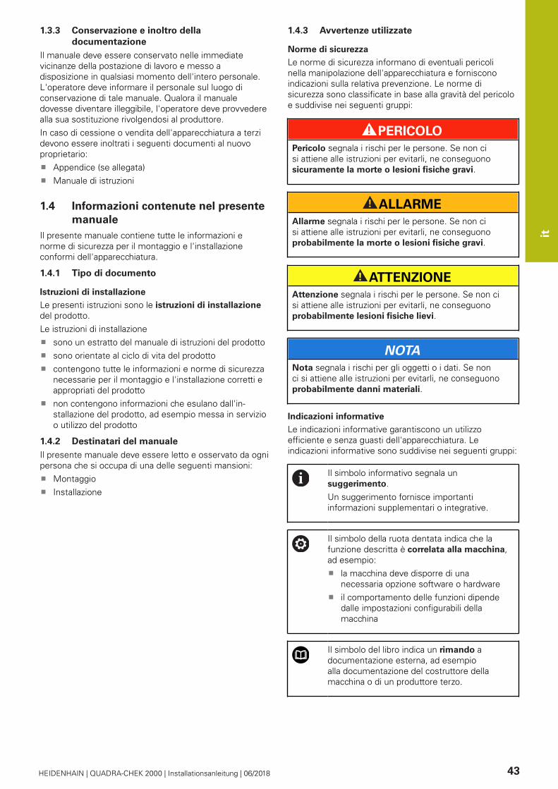
it
HEIDENHAIN | QUADRA-CHEK 2000 | Installationsanleitung | 06/2018 43
1.3.3 Conservazione e inoltro della
documentazione
Il manuale deve essere conservato nelle immediate
vicinanze della postazione di lavoro e messo a
disposizione in qualsiasi momento dell'intero personale.
L'operatore deve informare il personale sul luogo di
conservazione di tale manuale. Qualora il manuale
dovesse diventare illeggibile, l'operatore deve provvedere
alla sua sostituzione rivolgendosi al produttore.
In caso di cessione o vendita dell'apparecchiatura a terzi
devono essere inoltrati i seguenti documenti al nuovo
proprietario:
Appendice (se allegata)
Manuale di istruzioni
1.4 Informazioni contenute nel presente
manuale
Il presente manuale contiene tutte le informazioni e
norme di sicurezza per il montaggio e l'installazione
conformi dell'apparecchiatura.
1.4.1 Tipo di documento
Istruzioni di installazione
Le presenti istruzioni sono le istruzioni di installazione
del prodotto.
Le istruzioni di installazione
sono un estratto del manuale di istruzioni del prodotto
sono orientate al ciclo di vita del prodotto
contengono tutte le informazioni e norme di sicurezza
necessarie per il montaggio e l'installazione corretti e
appropriati del prodotto
non contengono informazioni che esulano dall'in-
stallazione del prodotto, ad esempio messa in servizio
o utilizzo del prodotto
1.4.2 Destinatari del manuale
Il presente manuale deve essere letto e osservato da ogni
persona che si occupa di una delle seguenti mansioni:
Montaggio
Installazione
1.4.3 Avvertenze utilizzate
Norme di sicurezza
Le norme di sicurezza informano di eventuali pericoli
nella manipolazione dell'apparecchiatura e forniscono
indicazioni sulla relativa prevenzione. Le norme di
sicurezza sono classificate in base alla gravità del pericolo
e suddivise nei seguenti gruppi:
PERICOLO
Pericolo segnala i rischi per le persone. Se non ci
si attiene alle istruzioni per evitarli, ne conseguono
sicuramente la morte o lesioni fisiche gravi.
ALLARME
Allarme segnala i rischi per le persone. Se non ci
si attiene alle istruzioni per evitarli, ne conseguono
probabilmente la morte o lesioni fisiche gravi.
ATTENZIONE
Attenzione segnala i rischi per le persone. Se non ci
si attiene alle istruzioni per evitarli, ne conseguono
probabilmente lesioni fisiche lievi.
NOTA
Nota segnala i rischi per gli oggetti o i dati. Se non
ci si attiene alle istruzioni per evitarli, ne conseguono
probabilmente danni materiali.
Indicazioni informative
Le indicazioni informative garantiscono un utilizzo
efficiente e senza guasti dell'apparecchiatura. Le
indicazioni informative sono suddivise nei seguenti gruppi:
Il simbolo informativo segnala un
suggerimento.
Un suggerimento fornisce importanti
informazioni supplementari o integrative.
Il simbolo della ruota dentata indica che la
funzione descritta è correlata alla macchina,
ad esempio:
la macchina deve disporre di una
necessaria opzione software o hardware
il comportamento delle funzioni dipende
dalle impostazioni configurabili della
macchina
Il simbolo del libro indica un rimando a
documentazione esterna, ad esempio
alla documentazione del costruttore della
macchina o di un produttore terzo.
it
44 HEIDENHAIN | QUADRA-CHEK 2000 | Installationsanleitung | 06/2018
1.4.4 Formattazione dei testi
Nel presente manuale si addotta la seguente
formattazione per evidenziare i testi:
Visualizzazione Significato
...
...
Contraddistingue una operazione e
il risultato della stessa
Esempio
Toccare OKIl messaggio viene chiuso
...
...
Contraddistingue un elenco
Esempio
Interfaccia TTL
Interfaccia EnDat
...
grassetto Contraddistingue menu, visualizza-
zioni e pulsanti
Esempio
Toccare ArrestaIl sistema operativo si arresta
Disinserire l'interruttore di
alimentazione dell'apparecchia-
tura
2 Sicurezza
2.1 Panoramica
Questo capitolo contiene informazioni importanti sulla
sicurezza per il montaggio e l'installazione corretti e
regolari dell'apparecchiatura.
2.2 Norme di sicurezza generali
Per il funzionamento del sistema si applicano le norme
di sicurezza generalmente riconosciute, come richiesto
in ambienti con apparecchiature sotto tensione. La
mancata osservanza di tali norme potrebbe danneggiare
l'apparecchiatura o procurare lesioni al personale.
Le norme di sicurezza all'interno delle singole aziende
sono naturalmente diverse. Se sussiste un conflitto
tra quanto riportato nel presente manuale e le norme
dell'azienda che utilizza il sistema, sono prioritarie le
disposizioni più severe.
2.3 Impiego previsto
Le apparecchiature della serie QUADRA-CHEK 2000 sono
elettroniche di misura e conteggio digitali di alta qualità
per il rilevamento di elementi 2D del profilo in applicazioni
tecniche di misura. Vengono impiegate principalmente su
macchine di misura e proiettori di profilo.
Le apparecchiature di questa serie
possono essere impiegate soltanto in applicazioni
commerciali e in campo industriale
devono essere montate su una base o un supporto
idoneo per l'impiego previsto
sono predisposte per l'impiego in interni e in un
ambiente in cui la presenza di umidità, conta-
minazione, olio e prodotti lubrificanti sia conforme ai
valori predefiniti nei dati tecnici
Le apparecchiature supportano l'impiego
di unità periferiche di produttori differenti.
HEIDENHAIN non fornisce alcuna indicazione
in merito all'impiego previsto di tali
unità. Occorre attenersi alle informazioni
sull'impiego previsto riportate nelle relative
documentazioni.

it
HEIDENHAIN | QUADRA-CHEK 2000 | Installationsanleitung | 06/2018 45
2.4 Impiego non previsto
Per tutte le apparecchiature della serie QUADRA-CHEK
2000 non sono ammesse in particolare le applicazioni
seguenti:
impiego e immagazzinaggio non conformi alle
condizioni di uso secondo "Dati tecnici"
impiego all'aperto
impiego in aree con pericolo di esplosioni
impiego delle apparecchiature della serie QUADRA-
CHEK 2000 come componente di una funzione di
sicurezza
2.5 Qualifica del personale
Il personale per montaggio e installazione deve
presentare la relativa qualifica per questi interventi ed
essere sufficientemente informato con l'aiuto della
documentazione dell'apparecchiatura e delle unità
periferiche collegate.
I requisiti del personale necessari per le singole attività
sull'apparecchiatura sono indicati nei relativi capitoli di
questo manuale.
Di seguito sono specificati più nel dettaglio i gruppi di
persone relativamente a qualifiche e mansioni.
Personale qualificato
Il personale qualificato viene formato dall'utilizzatore
nell'uso esteso e nella parametrizzazione. Il personale
qualificato è in grado, in base alla sua formazione, alle
sue conoscenze ed esperienze tecniche nonché alla sua
padronanza delle condizioni pertinenti, di eseguire gli
interventi impartiti riguardo la relativa applicazione e di
identificare e prevenire autonomamente i possibili pericoli.
Elettrotecnico specializzato
L'elettrotecnico specializzato è in grado, in base alla sua
formazione, alle sue conoscenze ed esperienze tecniche
nonché alla sua padronanza delle norme e condizioni
pertinenti, di eseguire gli interventi su impianti elettrici
e di identificare e prevenire autonomamente i possibili
pericoli. L'elettrotecnico specializzato è appositamente
qualificato per l'ambiente di lavoro in cui opera.
L'elettrotecnico specializzato deve soddisfare le condizioni
delle norme legali in vigore in materia di protezione
antinfortunistica.
2.6 Obblighi del gestore
Il gestore possiede l'apparecchiatura e le unità periferiche
oppure ha noleggiato entrambe. È responsabile in
qualsiasi momento dell'impiego previsto.
Il gestore deve
assegnare le diverse mansioni da eseguire sull'ap-
parecchiatura a personale qualificato, idoneo e
autorizzato
addestrare il personale in modo documentabile
riguardo i poteri e le mansioni
predisporre tutte le apparecchiature necessarie per il
personale al fine di soddisfare i compiti assegnati
garantire che l'apparecchiatura venga azionata esclu-
sivamente se in perfette condizioni tecniche
assicurare che l'apparecchiatura venga protetta da un
uso non autorizzato
2.7 Norme di sicurezza generali
La responsabilità di ogni sistema in cui viene
impiegato questo prodotto è del montatore o
dell'installatore di tale sistema.
L'apparecchiatura supporta l'impiego
di diverse unità periferiche di produttori
differenti. HEIDENHAIN non fornisce alcuna
indicazione in merito alle norme di sicurezza
specifiche di tali unità. Occorre attenersi alle
norme di sicurezza risultanti dalle relative
documentazioni. Se non presenti, devono
essere richieste ai relativi produttori.
Le norme di sicurezza specifiche, da osservare per le
singole attività sull'apparecchiatura, sono indicate nei
relativi capitoli del presente manuale.
2.7.1 Simboli sull'apparecchiatura
L'apparecchiatura è contrassegnata con i seguenti simboli.
Simbolo Significato
Osservare le norme di sicurezza sull'impian-
to elettrico o sul collegamento di alimenta-
zione prima di collegare l'apparecchiatura.
Connettore di terra funzionale secondo
IEC/EN 60204-1. Osservare le avvertenze
per l'installazione.
Sigillo del prodotto. Se il sigillo del prodot-
to viene rotto o rimosso, si estinguono la
garanzia legale e quella commerciale.

it
46 HEIDENHAIN | QUADRA-CHEK 2000 | Installationsanleitung | 06/2018
2.7.2 Norme di sicurezza sull'impianto elettrico
ALLARME
Contatto pericoloso con parti sotto tensione
all'apertura dell'apparecchiatura.
Ne potrebbero conseguire shock elettrici, ustioni o
morte.
Non aprire in nessun caso l'apparecchiatura
Far eseguire qualsiasi intervento soltanto dal
produttore
ALLARME
Rischio di pericolosa scarica di corrente attraverso
il corpo con contatto diretto o indiretto con parti
sotto tensione.
Ne potrebbero conseguire shock elettrici, ustioni o
morte.
Far eseguire qualsiasi intervento sull'impianto
elettrico e su componenti sotto tensione soltanto da
un tecnico specializzato e qualificato
Per il collegamento di alimentazione e tutti
i collegamenti delle interfacce utilizzare
esclusivamente cavi e connettori realizzati a norma
Far sostituire immediatamente dal costruttore
componenti elettrici danneggiati
Controllare regolarmente tutti i cavi collegati
e le prese dell'apparecchiatura. Eliminare
immediatamente eventuali difetti, ad esempio
collegamenti allentati o cavi danneggiati
NOTA
Danno dei componenti interni dell'apparecchiatura!
La garanzia legale e quella commerciale decadono se si
apre l'apparecchiatura.
Non aprire in nessun caso l'apparecchiatura
Far eseguire qualsiasi intervento soltanto dal
produttore dell'apparecchiatura
3 Trasporto e immagazzinaggio
3.1 Panoramica
Questo capitolo contiene le informazioni su trasporto,
immagazzinaggio come pure standard di fornitura e
accessori dell'apparecchiatura.
Le operazioni successive devono essere
eseguite soltanto da personale specializzato.
Ulteriori informazioni: "Qualifica del
personale", Pagina 45
3.2 Disimballaggio dell'apparecchiatura
Aprire in alto il cartone di imballaggio.
Rimuovere il materiale di imballaggio.
Rimuovere il contenuto.
Controllare se la fornitura è completa.
Controllare se la fornitura ha subito danni durante il
trasporto.
3.3 Standard di fornitura e accessori
3.3.1 Standard di fornitura
Lo standard di fornitura comprende gli articoli specificati di
seguito.
Denominazione Descrizione
Parte demo 2D
Apparecchiatura
Manuale di istruzioni
Istruzioni di installazione
Appendice (opzionale)

it
HEIDENHAIN | QUADRA-CHEK 2000 | Installationsanleitung | 06/2018 47
3.3.2 Accessori
Le opzioni software devono essere abilitate
sull'apparecchiatura tramite una chiave
di licenza. I relativi componenti hardware
possono essere impiegati soltanto dopo
l'abilitazione della relativa opzione software.
Gli accessori opzionali elencati di seguito possono essere
ordinati da HEIDENHAIN:
Accessori Denominazione ID
per installazione
Cavo di collegamento
USB
354770-xx
Cavo di alimentazione 223775-01
Adattatore 2 Vpp 1089216-01
Interruttore a pedale 681041-04
Adattatore TTL 1089210-01
Adattatore 11 µApp 1089213-01
Adattatore 1 Vpp 1089214-01
per montaggio
Supporto Multi-Pos 1089230-08
Base di supporto Duo-
Pos
1089230-06
Base di supporto Multi-
Pos
1089230-07
per opzione software OED
Cavo a fibra ottica 681049-xx
Collegamento cavo FO 681049-xx
Supporto 681050-xx
3.4 In caso di danni dovuti al trasporto
Richiedere la conferma del danno da parte dello
spedizioniere
Conservare il materiale di imballaggio per la verifica
Informare il mittente riguardo i danni
Mettersi in contatto con la filiale o il costruttore della
macchina per i ricambi
In caso di danni dovuti al trasporto:
Conservare il materiale di imballaggio per la
verifica
Contattare HEIDENHAIN o il costruttore
della macchina
Lo stesso vale anche per i danni di trasporto
delle richieste di ricambi.
3.5 Reimballaggio e immagazzinaggio
Imballare e immagazzinare l'apparecchiatura con cautela e
conformemente alle condizioni qui citate.
3.5.1 Imballaggio dell'apparecchiatura
Il reimballaggio deve essere il più possibile conforme a
quello originale.
Applicare tutti i componenti di montaggio e le
coperture antipolvere all'apparecchiatura allo
stesso modo in cui si trovavano alla consegna
dell'apparecchiatura o imballarli come erano imballati
Imballare l'apparecchiatura in modo tale che
vengano attenuati gli urti e le vibrazioni durante il
trasporto,
non possa penetrare polvere o umidità
Porre tutti gli accessori in dotazione nell'imballaggio
Ulteriori informazioni: "Standard di fornitura e
accessori", Pagina 46
Allegare tutta la documentazione inclusa nello standard
di fornitura
Ulteriori informazioni: "Conservazione e inoltro della
documentazione", Pagina 43
Per resi dell'apparecchiatura per interventi di
riparazione al Servizio Assistenza:
Spedire l'apparecchiatura senza accessori,
senza encoder e senza unità periferiche.
3.5.2 Immagazzinaggio dell'apparecchiatura
Imballare l'apparecchiatura come descritto sopra
Osservare le disposizioni per le condizioni ambientali
Ulteriori informazioni: "Dati tecnici", Pagina 53
Verificare l'eventuale presenza di danni
sull'apparecchiatura dopo ogni trasporto o
immagazzinaggio prolungato

it
48 HEIDENHAIN | QUADRA-CHEK 2000 | Installationsanleitung | 06/2018
4 Montaggio
4.1 Panoramica
Questo capitolo descrive il montaggio
dell'apparecchiatura. Sono riportate qui le istruzioni per
il montaggio corretto dell'apparecchiatura su base o
supporto.
Le operazioni successive devono essere
eseguite soltanto da personale specializzato.
Ulteriori informazioni: "Qualifica del
personale", Pagina 45
4.2 Assemblaggio dell'apparecchiatura
Istruzioni di montaggio generali
L'attacco per le varianti di montaggio si trova sul retro
dell'apparecchiatura. La sagoma dei fori di fissaggio
corrisponde a un reticolo di 50 mm x 50 mm.
Ulteriori informazioni: "H", Pagina 175
Il materiale per il fissaggio delle varianti di montaggio
sull'apparecchiatura è allegato agli accessori.
Sono inoltre richiesti:
Cacciavite Torx T20
Cacciavite Torx T25
Chiave a brugola misura 2,5 (base di supporto Duo-
Pos)
Materiale per il fissaggio su una superficie di appoggio
Per l'impiego previsto l'apparecchiatura deve
essere montata su una base o su un supporto.
Montaggio su base di supporto Duo-Pos
La base di supporto Duo-Pos può essere avvitata
all'apparecchiatura con una inclinazione di 20° o di 45°.
Se la base di supporto Duo-Pos viene avvitata
all'apparecchiatura con un'inclinazione di
45°, l'apparecchiatura deve essere fissata
all'estremità superiore della fessura di
montaggio. Utilizzare un cavo di alimentazione
con connettore ad angolo.
Fissare la base di supporto con le viti a esagono cavo
M4 x 8 ISO 7380 in dotazione ai fori filettati inferiori sul
retro dell'apparecchiatura
Attenersi alla coppia di serraggio
ammessa di 2,6 Nm
Avvitare la base su una superficie utilizzando la fessura
di montaggio (larghezza = 4,5 mm)
oppure
Installare l'apparecchiatura liberamente nella sede
desiderata
Posare i cavi dalla parte posteriore attraverso i due
manicotti della base di supporto e condurli attraverso le
aperture laterali ai relativi connettori
Ulteriori informazioni: "C", Pagina 4
Dimensioni della base di supporto Duo-Pos
Ulteriori informazioni: "J", Pagina 176
4.2.1 Montaggio su base di supporto Multi-Pos
Fissare la base di supporto con le viti a testa svasata
M4 x 8 ISO 14581 (colore nero) in dotazione ai fori
filettati sul retro dell'apparecchiatura
Attenersi alla coppia di serraggio
ammessa di 2,6 Nm
Avvitare su richiesta la base su una superficie
utilizzando due viti M5 dal basso.
Regolare l'angolo di inclinazione desiderato
Fissare la base di supporto: serrare la vite T25
Attenersi alla coppia di serraggio per la
vite T25
Coppia di serraggio raccomandata:
5,0 Nm
Coppia di serraggio massima ammessa:
15,0 Nm
Posare i cavi dalla parte posteriore attraverso i due
manicotti della base di supporto e condurli attraverso le
aperture laterali ai relativi connettori
Ulteriori informazioni: "D", Pagina 4
Dimensioni della base di supporto Multi-Pos
Ulteriori informazioni: "K", Pagina 176

it
HEIDENHAIN | QUADRA-CHEK 2000 | Installationsanleitung | 06/2018 49
4.2.2 Montaggio su supporto Multi-Pos
Fissare il supporto con le viti a testa svasata
M4 x 8 ISO 14581 (colore nero) in dotazione ai fori
filettati sul retro dell'apparecchiatura
Attenersi alla coppia di serraggio
ammessa di 2,6 Nm
Montare il supporto con la vite M8 in dotazione, le
rondelle, la staffa di supporto e il dado esagonale M8
su un braccio
Regolare l'angolo di inclinazione desiderato
Fissare il supporto: serrare la vite T25
Attenersi alla coppia di serraggio per la
vite T25
Coppia di serraggio raccomandata:
5,0 Nm
Coppia di serraggio massima ammessa:
15,0 Nm
Posare i cavi dalla parte posteriore attraverso i due
manicotti del supporto e condurli attraverso le aperture
laterali ai relativi connettori
Ulteriori informazioni: "E", Pagina 4
Dimensioni del supporto Multi-Pos
Ulteriori informazioni: "L", Pagina 177
5 Installazione
5.1 Panoramica
Questo capitolo descrive l'installazione
dell'apparecchiatura. Sono riportate qui informazioni
sui collegamenti dell'apparecchiatura e istruzioni sul
collegamento regolare di unità periferiche.
Le operazioni successive devono essere
eseguite soltanto da personale specializzato.
Ulteriori informazioni: "Qualifica del
personale", Pagina 45
5.2 Informazioni generali
NOTA
Disturbi dovuti alle fonti di elevate emissioni
elettromagnetiche!
Unità periferiche quali convertitori di frequenza o
azionamenti possono causare disturbi.
Per incrementare l'insensibilità ai disturbi dovuti agli
influssi elettromagnetici:
impiegare il connettore di terra funzionale opzionale
secondo IEC/EN 60204-1
impiegare soltanto unità periferiche USB con
una schermatura universale mediate ad esempio
pellicola blindata e treccia metallica oppure
alloggiamento metallico. Il grado di copertura della
treccia schermante deve essere pari all'85% o
maggiore. La schermatura deve essere collegata a
sua volta ai connettori (collegamento a 360°).
NOTA
Esecuzione o allentamento di collegamenti!
Pericolo di danneggiare i componenti interni.
Eseguire o allentare i collegamenti solo con
apparecchiatura disinserita!
it
50 HEIDENHAIN | QUADRA-CHEK 2000 | Installationsanleitung | 06/2018
NOTA
Scarica elettrostatica (ESD)!
L'apparecchiatura contiene componenti a rischio
elettrostatico che possono essere distrutti da scarica
elettrostatica.
Rispettare assolutamente le norme di sicurezza per
la gestione di componenti ESD sensibili
Non toccare mai i pin di collegamento senza
regolare messa a terra
In caso di interventi sui collegamenti
dell'apparecchiatura indossare un bracciale ESD con
messa a terra
NOTA
Danni all'apparecchiatura a causa del cablaggio
errato.
Il cablaggio errato di ingressi o uscite può comportare
danni all'apparecchiatura o alle unità periferiche.
Attenersi alle piedinature e ai dati tecnici
dell'apparecchiatura
Lasciare liberi i pin e i conduttori inutilizzati
Ulteriori informazioni: "Dati tecnici", Pagina 53
5.3 Panoramica dell'apparecchiatura
I connettori sul retro dell'apparecchiatura sono protetti da
contaminazione e danni con coperture antipolvere.
NOTA
La mancanza delle coperture antipolvere può
determinare contaminazione e danni!
Se sui connettori inutilizzati non vengono applicate
le coperture antipolvere, i contatti di collegamento
possono essere compromessi nella loro funzionalità o
distrutti.
Eliminare le coperture antipolvere soltanto se sono
collegati encoder o unità periferiche.
Se si elimina un encoder o un'unità periferica,
riapplicare le coperture antipolvere sull'attacco.
Il tipo di attacco per encoder può
essere diverso a seconda della versione
dell'apparecchiatura.
Retro dell'apparecchiatura senza coperture antipolvere
Ulteriori informazioni: "A", Pagina 4
Connettori indipendenti dalle opzioni software:
2 X113: connettore Sub-D a 15 poli per interruttore a
pedale, sistemi di tastatura
Connettori Sub-D per encoder, di default 2 ingressi
attivati, 1 ingresso aggiuntivo opzionale attivabile
X1-X3: versione con connettori Sub-D a 15 poli per
encoder con interfaccia 1 VPP
X21-X23: variante con connettori Sub-D a 9 poli per
encoder con interfaccia TTL
3
X1, X2, X21: versione con due connettori Sub-D a 15
poli per encoder con interfaccia 1 VPP e un connettore
Sub-D a 9 poli per encoder con interfaccia TTL
Connettore Ethernet RJ454
X116: connettore per comunicazione e scambio dati
con sistemi successivi/PC
Porta USB5
X32: connettore USB 2.0 Hi-Speed (tipo A) per
stampante, apparecchiature di immissione o memoria
di massa USB
6 Connettore di terra funzionale secondo IEC/EN
60204-1
7 X100: connettore e attacco di alimentazione
8 Altoparlante
Connettori correlati alle opzioni software:
Attacchi per fibra ottica per il rilevamento del punto di
misura
X107: ingresso di riferimento per cavo FO provenien-
te dalla sorgente luminosa
1
X108: ingresso per cavo FO proveniente dallo scher-
mo di proiezione

it
HEIDENHAIN | QUADRA-CHEK 2000 | Installationsanleitung | 06/2018 51
5.4 Collegamento degli encoder
Rimuovere le coperture antipolvere e conservarle.
Posare i cavi a seconda della variante di montaggio.
Ulteriori informazioni: "Assemblaggio
dell'apparecchiatura", Pagina 48
Collegare in modo fisso gli encoder ai relativi attacchi.
Ulteriori informazioni: "Panoramica
dell'apparecchiatura", Pagina 50
Per connettori con viti: non serrare troppo le viti.
Piedinatura X1, X2, X3
Ulteriori informazioni: "1 VSS", Pagina 178
Piedinatura X21, X22, X23
Ulteriori informazioni: "TTL", Pagina 178
5.5 Collegamento della fibra ottica
Rimuovere le coperture antipolvere e conservarle
Posare i cavi FO a seconda della variante di montaggio.
Ulteriori informazioni: "Assemblaggio
dell'apparecchiatura", Pagina 48
Attenersi alle specifiche del produttore
per il raggio di curvatura massimo dei
cavi FO
Collegare il cavo FO della sorgente luminosa
(riferimento) al connettore X107.
Collegare il cavo FO proveniente dallo schermo di
proiezione al connettore X108.
Ulteriori informazioni: "Panoramica dell'apparecchiatura",
Pagina 50
Piedinatura X107, X108
Ulteriori informazioni: "OED", Pagina 178
5.6 Cablaggio di ingressi e uscite di
commutazione
A seconda della periferica da collegare
può essere necessario l'intervento di un
elettrotecnico specializzato per le attività di
collegamento.
Esempio: superamento della bassa tensione di
protezione (SELV)
Ulteriori informazioni: "Qualifica del
personale", Pagina 45
L'apparecchiatura soddisfa i requisiti della
norma IEC 61010-1 soltanto se la periferia
viene alimentata da un circuito secondario
con corrente limitata a norma IEC 61010-13rd
Ed., par. 9.4 o con potenza limitata a norma
IEC 60950-12nd Ed., par. 2.5 o da un circuito
secondario della classe 2 a norma UL1310.
Invece della norma IEC 61010-13rd Ed., par. 9.4
è possibile impiegare anche i relativi paragrafi
delle norme DIN EN 61010-1, EN 61010-1, UL
61010-1 e CAN/CSA-C22.2 No. 61010-1 ovvero
invece della norma IEC 60950-12nd Ed., par. 2.5 i
relativi paragrafi delle norme DIN EN 60950-1,
EN 60950-1, UL 60950-1, CAN/CSA-C22.2 No.
60950-1.
Rimuovere le coperture antipolvere e conservarle.
Posare i cavi a seconda della variante di montaggio.
Ulteriori informazioni: "Assemblaggio
dell'apparecchiatura", Pagina 48
Collegare in modo fisso il cavo dell'unità periferica ai
relativi attacchi.
Ulteriori informazioni: "Panoramica dell'apparecchiatura",
Pagina 50
Per connettori con viti: non serrare troppo le viti.
Gli ingressi e le uscite digitali o analogici
devono essere attribuiti alla relativa funzione
di commutazione nelle impostazioni delle
apparecchiature.
Piedinatura X113
Ulteriori informazioni: "X113", Pagina 179
5.7 Collegamento della stampante
Collegamento della stampante USB
Rimuovere le coperture antipolvere e conservarle.
Posare i cavi a seconda della variante di montaggio.
Ulteriori informazioni: "Assemblaggio
dell'apparecchiatura", Pagina 48
Collegare la stampante USB al connettore USB tipo
A (X32). Il connettore del cavo USB deve essere
completamente inserito nella presa
Ulteriori informazioni: "Panoramica
dell'apparecchiatura", Pagina 50
Piedinatura X32
Ulteriori informazioni: "USB", Pagina 178

it
52 HEIDENHAIN | QUADRA-CHEK 2000 | Installationsanleitung | 06/2018
Collegamento della stampante Ethernet
Rimuovere le coperture antipolvere e conservarle.
Posare i cavi a seconda della variante di montaggio.
Ulteriori informazioni: "Assemblaggio
dell'apparecchiatura", Pagina 48
Collegare la stampante Ethernet con l'aiuto di un
comune cavo CAT.5 al connettore Ethernet X116.
Il connettore del cavo deve essere ben inserito
nell'attacco.
Ulteriori informazioni: "Panoramica
dell'apparecchiatura", Pagina 50
Piedinatura X116
Ulteriori informazioni: "RJ45", Pagina 179
5.8 Collegamento di scanner di codici a
barre
All'apparecchiatura è possibile collegare i
seguenti scanner di codici a barre:
COGNEX DataMan 8600 (con modulo
seriale per USB)
Rimuovere le coperture antipolvere e conservarle.
Posare i cavi a seconda della variante di montaggio.
Ulteriori informazioni: "Assemblaggio
dell'apparecchiatura", Pagina 48
Collegare lo scanner di codici a barre al connettore
USB tipo A (X32). Il connettore del cavo USB deve
essere completamente inserito nella presa
Ulteriori informazioni: "Panoramica
dell'apparecchiatura", Pagina 50
Piedinatura X32
Ulteriori informazioni: "USB", Pagina 178
5.9 Collegamento delle apparecchiature
di immissione
Rimuovere le coperture antipolvere e conservarle.
Posare i cavi a seconda della variante di montaggio.
Ulteriori informazioni: "Assemblaggio
dell'apparecchiatura", Pagina 48
Collegare il mouse USB o la tastiera USB al connettore
USB tipo A (X32). Il connettore del cavo USB deve
essere completamente inserito nella presa
Ulteriori informazioni: "Panoramica
dell'apparecchiatura", Pagina 50
Piedinatura X32
Ulteriori informazioni: "USB", Pagina 178
5.10 Collegamento dell'unità periferica di
rete
Rimuovere le coperture antipolvere e conservarle.
Posare i cavi a seconda della variante di montaggio.
Ulteriori informazioni: "Assemblaggio
dell'apparecchiatura", Pagina 48
Collegare l'unità periferica di rete con l'aiuto di un
comune cavo CAT.5 al connettore Ethernet X116.
Il connettore del cavo deve essere ben inserito
nell'attacco.
Ulteriori informazioni: "Panoramica dell'apparecchiatura",
Pagina 50
Piedinatura X116
Ulteriori informazioni: "RJ45", Pagina 179
5.11 Collegamento della tensione di
alimentazione
ALLARME
Pericolo di scosse elettriche!
Le apparecchiature non regolarmente messe a terra
possono causare lesioni serie o morte a causa di
scosse elettriche.
Utilizzare un cavo di alimentazione tripolare
Assicurarsi di collegare il conduttore di protezione
(terra) al PE dell’edificio
ALLARME
Pericolo di incendio a causa del cavo di
alimentazione errato!
L'impiego di cavi di alimentazione che non soddisfano
requisiti del luogo di installazione può comportare il
pericolo di incendio.
Utilizzare soltanto un cavo di alimentazione che
soddisfi almeno i requisiti nazionali del luogo di
installazione.
Collegare l'attacco di alimentazione al cavo di
alimentazione conforme ai requisiti con la presa di
alimentazione dotata di conduttore di terra
Ulteriori informazioni: "Panoramica dell'apparecchiatura",
Pagina 50
Piedinatura X100
Ulteriori informazioni: "X100", Pagina 178

it
HEIDENHAIN | QUADRA-CHEK 2000 | Installationsanleitung | 06/2018 53
6 Dati tecnici
6.1 Panoramica
Questo capitolo contiene una panoramica dei
dati dell'apparecchiatura e i disegni con le quote
dell'apparecchiatura e di collegamento.
6.2 Dati dell'apparecchiatura
Apparecchiatura
Corpo frontale fresato in alluminio + retro
pressofuso
Dimensioni 200 mm x 169 mm x 41 mm
Tipo di fissaggio,
dimensioni di
collegamento
Sagoma dei fori di fissaggio
50 mm x 50 mm
Display
Schermo LCD widescreen (15:9)
a colori 17,8 cm (7")
800 x 480 pixel
Passo di
visualizzazione
impostabile, min. 0,00001 mm
Interfaccia utente interfaccia utente (GUI) con touch
screen
Dati elettrici
Tensione di
alimentazione
100 V AC ... 240 V AC (±10%)
50 Hz ... 60 Hz (±5%)
potenza in ingresso max 38 W
Batteria tampone batteria al litio tipo CR2032; 3,0 V
Categoria di
sovratensione
II
Numero di
ingressiencoder
2 (1 ingresso aggiuntivo attivabile
tramite opzione software)
Interfacce encoder 11 μA: corrente
massima 300 mA,
frequenza in ingresso max 150 kHz
1 VPP: corrente massima
300 mA, frequenza in ingresso
max 400 kHz
TTL: corrente
massima 300 mA,
frequenza in ingresso max 5 MHz
Interpolazione a
1 VPP
x4.096
Collegamen-
to sistema di
tastatura
tensione di alimentazione 5 V
DC o 12 V DC
uscita di commutazione di 5 V
o a potenziale zero
4 ingressi digitali
1 ingresso digitale
lunghezza cavo max con cavo
HEIDENHAIN da 30 m
Dati elettrici
Collegamento con
fibra ottica
2 connettori femmina F-
SMA (denominazione filetto
1/4-36 UNS-2A)
Ingressi digitali TTL 0 V DC ... +5 V DC
Uscite digitali TTL 0 V DC ... +5 V DC
Carico massimo 1 kΩ
Interfaccia dati 1 USB 2.0 Hi-Speed (tipo A),
corrente max 500 mA per ogni
porta USB
1 Ethernet 10/100 MBit/1 GBit
(RJ45)
Ambiente
Temperatura di
lavoro
0 °C ... +45 °C
Temperatura di
immagazzinaggio
–20 °C ... +70 °C
Umidità relativa
dell'aria
10% ... 80% u.r. senza formazione
di condensa
Altezza ≤ 2000 m
Informazioni generali
Direttive Direttiva EMC 2014/30/UE
Direttiva Bassa Tensione
2014/35/UE
Direttiva RoHS 2011/65/UE
Grado di
contaminazione
2
Grado di
protezione
EN 60529
fronte e lati: IP65
retro: IP40
Peso 1,3 kg
con base di supporto Duo-Pos:
1,45 kg
con base di supporto Multi-Pos:
1,95 kg
con supporto Multi-Pos: 1,65 kg
6.3 Dimensioni dell'apparecchiatura
Ulteriori informazioni: Pagina 175 e pagine seguenti.
Tutte le quote nel disegno sono rappresentate in mm.

es
54 HEIDENHAIN | QUADRA-CHEK 2000 | Installationsanleitung | 06/2018
1 Nociones básicas
1.1 Resumen
Este capítulo contiene información acerca del presente
producto y el presente manual.
1.2 Información del producto
Denominación del
producto
ID Indice
QUADRA-CHEK 2000 1089180-xx ---
La placa de características se encuentra en la parte
posterior del equipo.
Ejemplo:
2
3
1
1 Denominación del producto
2 Índice
3 N.º de identificación (ID)
1.3 Documentación del producto
1.3.1 Validez de la documentación
Antes de utilizar la documentación y el equipo debe
comprobarse que la documentación y el equipo
concuerden.
Comparar el número de identificación indicado en la
documentación y el índice con los datos indicados en
la etiqueta del modelo del equipo
Si los números de identificación y los índices
concuerdan, la documentación es válida
Si los números de identificación y los
índices no concuerdan y, por lo tanto, la
documentación no es válida, puede encontrar
la documentación actual del equipo en
www.heidenhain.de.
1.3.2 Instrucciones para la lectura de la
documentación
ADVERTENCIA
¡Accidentes mortales, lesiones o daños
materiales originados por la no observancia de la
documentación!
Si no se observan las indicaciones de la
Documentación pueden producirse accidentes
mortales, lesiones o daños materiales.
Leer la documentación cuidadosa y completamente
Conservar la documentación para futuras consultas
La tabla siguiente contiene las partes que componen la
documentación en el orden secuencial de su prioridad de
lectura.
Documentación Descripción
Anexo Un anexo complementa o reempla-
za los contenidos correspondien-
tes del modo de empleo y, dado
el caso, también del manual de
instrucciones de instalación.
Si el suministro contiene un anexo,
este tiene la máxima prioridad
de lectura. Todos los contenidos
restantes de la documentación
mantienen su validez.
Manual de instruc-
ciones de instala-
ción
El manual contiene todas las
informaciones e instrucciones de
seguridad necesarias para montar
e instalar correctamente el equipo.
Siendo un extracto del Manual de
instrucciones, el Manual de instala-
ción se envía con el suministro.
El manual de instalación es el
segundo en prioridad de lectura.
Manual de instruc-
ciones de uso
El manual de instrucciones de
uso contiene todas las informa-
ciones e instrucciones de seguri-
dad necesarias para hacer funcio-
nar correctamente el equipo y
de acuerdo con el fin al que está
destinado. El Manual de instruc-
ciones está incluido en el medio
de almacenamiento suministra-
do, y asimismo puede descargar-
se desde www.heidenhain.de
se está descargando. Antes de la
puesta en marcha del equipo, es
imprescindible leer el Manual de
instrucciones.
Dicho Manual de instrucciones
tiene la tercera prioridad de lectura.
¿Desea modificaciones o ha detectado un error?
Realizamos un mejora continua en nuestra
documentación. Puede ayudarnos en este objetivo
indicándonos sus sugerencias de modificaciones en la
siguiente dirección de correo electrónico:

es
HEIDENHAIN | QUADRA-CHEK 2000 | Installationsanleitung | 06/2018 55
1.3.3 Conservación y divulgación de la
documentación
El manual debe guardarse en la proximidad inmediata
del puesto de trabajo y debe estar a disposición de todo
el personal en todo momento. El explotador del equipo
deberá informar al personal de dónde se guarda este
manual. Si el manual se ha vuelto ilegible, el explotador
del equipo deberá pedir al fabricante un nuevo ejemplar.
Al transferir o revender el equipo a terceros, deberán
transferirse al nuevo propietario los documentos
siguientes:
Anexo (en el caso de que se haya entregado con el
equipo)
Manual de instrucciones de uso
1.4 Acerca de este manual
Este manual contiene toda la información e instrucciones
de seguridad necesarias para montar e instalar
correctamente el equipo.
1.4.1 Tipo de documento
Manual de instrucciones de instalación
El presenta manual es el Manual de instalación del
producto.
El manual de instalación
es un extracto del Manual de instrucciones del
producto
está orientado al ciclo de vida del producto
contiene toda la información e instrucciones de
seguridad necesarias para montar e instalar el
producto correctamente y de acuerdo con el uso
previsto
no contiene información no pertinente para la
instalación del producto, como por ejemplo la puesta
en marcha del producto o el funcionamiento del
producto
1.4.2 Grupos destinatarios del manual de
instrucciones
Todas las personas que intervengan en uno de los
trabajos siguientes deberán leer y observar el presente
manual de instrucciones:
Montaje
Instalación
1.4.3 Instrucciones empleadas
Indicaciones para la seguridad
Los avisos de seguridad advierten contra los peligros en la
manipulación del equipo y proporcionan las instrucciones
para evitarlos. Los avisos de seguridad se clasifican en
función de la gravedad del peligro y se subdividen en los
grupos siguientes:
PELIGRO
Peligro indica un riesgo para las personas. Si no se
observan las instrucciones para la eliminación de
riesgos es seguro que el peligro ocasionará la muerte
o lesiones graves.
ADVERTENCIA
Advertencia indica un riesgo para las personas. Si
no se observan las instrucciones para la eliminación
de riesgos es previsible que el riesgo ocasionará la
muerte o lesiones graves.
PRECAUCIÓN
Precaución indica un peligro para las personas. Si no
se observan las instrucciones para la eliminación de
riesgos es previsible que el riesgo ocasione lesiones
leves.
INDICACIÓN
Indicación indica un peligro para los equipos o para
los datos. Si no se observan las instrucciones para
la eliminación de riesgos es previsible que el riesgo
ocasione un daño material.
Notas de información
Las notas de información garantizan un uso del equipo
eficiente y exento de fallos. Las notas de información se
clasifican en los grupos siguientes:
El símbolo informativo representa un consejo.
Un consejo proporciona información adicional
o complementaria importante.
El símbolo de rueda dentada indica que la
función descrita depende de la máquina, p.
ej.:
Es imprescindible que la máquina disponga
de un opción necesaria de software o
hardware
El comportamiento de las funciones
depende de los ajustes configurables de la
máquina
El símbolo de un libro representa una
referencia cruzada a documentación externa,
p. ej., documentación del fabricante de la
máquina o de un tercero.

es
56 HEIDENHAIN | QUADRA-CHEK 2000 | Installationsanleitung | 06/2018
1.4.4 Distinciones de texto
En este manual se emplean las siguientes distinciones de
texto:
Representación Significado
...
...
identifica un paso de una acción y el
resultado de una acción
Ejemplo:
Pulsar en OKEl mensaje se cierra
...
...
identifica una lista o relación
Ejemplo:
Interfaz TTL
Interfaz EnDat
...
negrita identifica menús, indicaciones y
botones
Ejemplo:
Pulsar en PararEl sistema operativo se detiene
Desconectar el equipo mediante
el interruptor de red
2 Seguridad
2.1 Resumen
Este capítulo contiene información importante sobre
la seguridad para montar e instalar el equipo de forma
correcta.
2.2 Medidas generales de seguridad
Para el funcionamiento del sistema, son aplicables las
medidas de seguridad reconocidas universalmente, como
las que se requieren en particular en la manipulación de
aparatos con tensión eléctrica. La no consideración de
estas prescripciones de seguridad puede tener como
consecuencia daños en el aparato o lesiones en las
personas.
Las prescripciones de seguridad pueden variar según
cada empresa. En el caso de conflicto entre el contenido
de esta guía rápida y las regulaciones internas de una
empresa en la que vaya a utilizarse este aparato deben
acatarse siempre las regulaciones más severas.
2.3 Utilización conforme al uso previsto
Los dispositivos de la serie QUADRA-CHEK 2000 son
electrónicas de evaluación digitales de alta calidad para la
detección de elementos de contorno 2Den aplicaciones
metrológicas. Los dispositivos se utilizan principalmente
en máquinas de medición y proyectores del perfil.
Los dispositivos de esta serie
solo se pueden usar en aplicaciones profesionales y en
un entorno industrial
deben estar montados para un uso previsto en una
base o soporte adecuado
son para su uso en interiores y en un entorno previsto
en el que la carga por humedad, suciedad, aceite y
lubricantes corresponda a las especificaciones de los
datos técnicos
Los dispositivos contemplan el uso de
equipos periféricos de diferentes fabricantes.
HEIDENHAIN no puede pronunciarse sobre el
uso conforme a lo previsto de dichos aparatos.
La información relativa al uso conforme a lo
previsto contenida en las documentaciones
correspondientes deberá tenerse en cuenta.

es
HEIDENHAIN | QUADRA-CHEK 2000 | Installationsanleitung | 06/2018 57
2.4 Utilización no conforme al uso
previsto
Las siguientes aplicaciones en particular son inadmisibles
para todos los dispositivos de la serie QUADRA-CHEK
2000:
Uso y almacenamiento fuera de las condiciones de
funcionamiento según "Características técnicas"
Uso al aire libre
Uso en zonas con riesgo de explosión
Uso de los dispositivos de la serie QUADRA-CHEK
2000 como parte de una función de seguridad
2.5 Cualificación del personal
El personal para el montaje e instalación deberá poseer
la cualificación correspondiente para dichos trabajos
y estar suficientemente informado con la ayuda de la
documentación del equipo y de la periferia conectada.
Los requisitos que debe cumplir el personal, que se
requieren para las distintas actividades del equipo, se
indican en los correspondientes capítulos del presente
manual.
A continuación se especifican con más detalle los grupos
de personas en cuanto a sus cualificaciones y tareas.
Personal especializado
El explotador del equipo proporcionará al personal
especializado la formación necesaria para el manejo
ampliado y la parametrización. Gracias a su formación
especializada, sus conocimientos y su experiencia, así
como su conocimiento de las disposiciones pertinentes,
el personal especializado estará capacitado para ejecutar
los trabajos encomendados relativos a la respectiva
aplicación, y para reconocer y evitar de forma autónoma
los posibles riesgos.
Electricista especializado
Gracias a su formación especializada, sus conocimientos
y su experiencia, así como su conocimiento de las normas
pertinentes, el electricista especializado estará capacitado
para ejecutar los trabajos encomendados relativos a
la respectiva aplicación, y para reconocer y evitar de
forma autónoma los posibles riesgos. El electricista
especializado ha recibido la formación especial para el
ámbito de trabajo en el que realiza su actividad.
El electricista especializado debe cumplir las
disposiciones de la normativa legal vigente para la
prevención de accidentes.
2.6 Obligaciones del explotador
El explotador es el propietario del equipo y de la periferia
o ha alquilado ambos. En todo momento, será el
responsable de que se haga el uso conforme a lo previsto.
El explotador debe:
asignar las diferentes tareas en el equipo a personal
cualificado, apropiado y autorizado
instruir al personal de forma comprobable acerca de
las autorizaciones
Proporcionar al personal todos los medios que precise
para poder ejecutar las tareas que tiene asignadas
asegurar que el equipo se hace funcionar en un estado
impecable técnicamente
asegurar que el equipo quede protegido contra un uso
no autorizado
2.7 Instrucciones de seguridad generales
La responsabilidad para cada sistema en
el que se utiliza este producto recae en el
montador o instalador de dicho sistema.
El equipo soporta la utilización de múltiples
aparatos periféricos de diferentes fabricantes.
HEIDENHAIN no puede pronunciarse sobre
las instrucciones de seguridad específicas
de dichos aparatos. Las instrucciones de
seguridad indicadas en las documentaciones
correspondientes deben tenerse en cuenta.
En el caso de que dichas documentaciones no
existan, deberán solicitarse a los fabricantes.
Las instrucciones de seguridad específicas, que
deben tenerse en cuenta en el equipo para las
diferentes actividades, están indicadas en los capítulos
correspondientes de este manual.
2.7.1 Símbolos en el equipo
El equipo está caracterizado por los símbolos siguientes:
Símbolo Significado
Es preciso tener en cuenta las adverten-
cias de seguridad respecto a las conexiones
eléctricas y a la conexión a la red de alimen-
tación, antes de conectar el equipo.
Conexión de tierra funcional conforme a
IEC/EN 60204-1. Tener en cuenta las indica-
ciones al respecto de la instalación.
Sello del producto. Si el sello del produc-
to está roto o ha sido retirado, se anula la
garantía.

es
58 HEIDENHAIN | QUADRA-CHEK 2000 | Installationsanleitung | 06/2018
2.7.2 Instrucciones de seguridad sobre el sistema
eléctrico
ADVERTENCIA
Al abrir el equipo, contacto peligroso con piezas
que conducen la electricidad.
La consecuencia puede ser una descarga eléctrica,
quemaduras o la muerte.
La caja no debe abrirse en ningún caso
Las intervenciones únicamente las podrá realizar el
fabricante
ADVERTENCIA
Riesgo de circulación peligrosa de electricidad a
través del cuerpo por contacto directo o indirecto
con piezas que conducen la electricidad.
La consecuencia puede ser una descarga eléctrica,
quemaduras o la muerte.
Los trabajos en el sistema eléctrico y en
componentes sometidos a tensión eléctrica
deberán encargarse a un especialista que cuente
con la debida formación
Para la conexión a la red y para todas las conexiones
de las interfaces deberán emplearse exclusivamente
conectores y cables prefabricados según normas
Deberá encargarse al fabricante la sustitución
inmediata de los componentes eléctricos
defectuosos
Comprobar a intervalos de tiempo regulares todos
los cables conectados y todas las hembrillas de
conexión del equipo Las deficiencias, tales como
conexiones flojas o cables chamuscados, deberán
subsanarse de inmediato
INDICACIÓN
Daño de componentes internos del equipo.
Si se abre el equipo, la garantía del producto queda
anulada.
La caja no debe abrirse en ningún caso
Las intervenciones únicamente las podrá realizar el
fabricante del equipo
3 Transporte y almacenamiento
3.1 Resumen
Este capítulo contiene información sobre el transporte
y el almacenamiento, así como sobre los elementos
suministrados y accesorios del equipo.
Los pasos siguientes únicamente podrán ser
ejecutados por personal especializado.
Información adicional: "Cualificación del
personal", Página 57
3.2 Desembalar el equipo
Abrir la caja de cartón de embalaje por la parte superior
Retirar el material de embalaje
Extraer el contenido
Comprobar que el suministro esté completo
Comprobar que el suministro no haya sufrido daños en
el transporte
3.3 Alcance del suministro y accesorios
3.3.1 Elementos suministrados
En el suministro se incluyen los artículos siguientes:
Denominación Descripción
Pieza de demostración en
2D
Equipo
Manual de instrucciones de
uso
Manual de instrucciones de
instalación
Anexo (de modo opcional)

es
HEIDENHAIN | QUADRA-CHEK 2000 | Installationsanleitung | 06/2018 59
3.3.2 Accesorios
Las opciones de software deben
desbloquearse en el equipo mediante
una clave de licencia. Los componentes
correspondientes de hardware solo pueden
utilizarse tras desbloquear la respectiva opción
de software.
Los accesorios mencionados a continuación se pueden
pedir opcionalmente a HEIDENHAIN:
Accesorio Denominación ID
para instalación
Enchufe adaptador de 11
µApp
1089213-01
Enchufe adaptador 1 Vpp 1089214-01
Cable de red 223775-01
Enchufe adaptador 2 Vpp 1089216-01
Conmutador de pie 681041-04
Cable de conexión USB 354770-xx
Enchufe adaptador TTL 1089210-01
para montaje
Soporte Multi-Pos 1089230-08
Pie de montaje Duo-Pos 1089230-06
Pie de montaje Multi-Pos 1089230-07
de la opción de software OED
Fibra óptica 681049-xx
Conexión del cable de
fibra óptica
681049-xx
Soporte 681050-xx
3.4 Si se ha producido algún daño
durante el transporte
Solicitar al transportista que confirme los daños
Guardar los materiales de embalaje para su posterior
examen.
Informar al remitente sobre los daños
Contactar con los distribuidores o fabricantes de la
máquina con respecto a las piezas de repuesto
En caso de haberse producido daños durante
el transporte:
Guardar los materiales de embalaje para su
posterior examen
Contactar con HEIDENHAIN o el fabricante
de la máquina
Esto aplica también para los daños en el
transporte en las peticiones de repuestos.
3.5 Reembalaje y almacenamiento
Embalar y almacenar el equipo cuidadosamente y
conforme a las condiciones que aquí se indican.
3.5.1 Embalar el equipo
El reembalaje deberá realizarse lo más igual que se pueda
al embalaje original.
Todas las piezas de montaje adosado y las tapas
de protección contra el polvo deben colocarse en
el equipo tal como estaban cuando se suministró
el equipo y deben embalarse tal como estaban
embaladas
Embalar el equipo de tal modo que
los impactos y las sacudidas durante el transporte
queden amortiguadas
y no pueda penetrar ni el polvo ni la humedad
Embalar todos los accesorios suministrados
Información adicional: "Alcance del suministro y
accesorios", Página 58
Adjuntar toda la documentación dispuesta en el
embalaje suministrado
Información adicional: "Conservación y divulgación
de la documentación", Página 55
En las devoluciones del equipo al servicio
técnico postventa para reparación:
Enviar el equipo sin accesorios ni sistemas
de medida y aparatos periféricos
3.5.2 Almacenar el equipo
Embalar el equipo tal como se ha descrito
anteriormente
Observar las disposiciones relativas a las condiciones
medioambientales
Información adicional: "Características técnicas",
Página 65
Después de cada transporte y tras un almacenamiento
prolongado, examinar el equipo para comprobar que
no ha sufrido daños

es
60 HEIDENHAIN | QUADRA-CHEK 2000 | Installationsanleitung | 06/2018
4 Montaje
4.1 Resumen
Este capítulo describe el montaje del equipo. Aquí puede
encontrar instrucciones de cómo montar el equipo en
soportes o soportes bisagra.
Los pasos siguientes únicamente podrán ser
ejecutados por personal especializado.
Información adicional: "Cualificación del
personal", Página 57
4.2 Ensamblaje del equipo
Indicaciones de montaje generales
La imagen ilustrando la variante de montaje se encuentra
en la parte posterior del equipo. El patrón del orificio de
fijación comprende una retícula de 50 mm x 50 mm.
Información adicional: "H", Página 175
El material para al fijación de la variante de montaje al
equipo se suministra junto con los accesorios.
Adicionalmente se precisa:
Destornillador Torx T20
Destornillador Torx T25
Llave hexagonal SW 2,5 (soporte bisagra Duo-Pos)
Material para la fijación sobre una superficie de asiento
Para utilizar el equipo conforme al uso
previsto, debe estar montado en un soporte
de pie o un soporte.
Montaje en soporte bisagra Duo-Pos
El pie de soporte Duo-Pos se puede enroscar al
equipo con una inclinación de 20° o bien con una
inclinación de 45°.
Cuando atornille el conmutador de pie Duo-
Pos con una inclinación de 45° al aparato,
deberá fijar el mismo al extremo superior de la
ranura de montaje. Utilice un cable de red con
un conector acodado.
Fijar el soporte bisagra con los tornillos Allen
suministrados M4 x 8 ISO 7380 a los orificios roscados
inferiores de la parte posterior del equipo
Respetar el par de apriete admisible de
2,6 Nm
Atornillar el soporte bisagra en la ranura de montaje
(anchura = 4,5 mm) sobre una superficie
o
Instalar el aparato en el lugar deseado
Pasar los cables desde la parte trasera por la abertura
del soporte bisagra y a través de las aberturas laterales
a las conexiones
Información adicional: "C", Página 4
Dimensiones del pie de soporte Duo-Pos
Información adicional: "J", Página 176
4.2.1 Montaje en soporte bisagra Multi-Pos
Fijar el soporte bisagra con los tornillos avellanados
suministrados M4 x 8 ISO 14581 (negro) a los orificios
roscados de la parte posterior del equipo
Respetar el par de apriete admisible de
2,6 Nm
Atornillar a una superficie el soporte bisagra opcional
con dos tornillos M5 desde la parte inferior
Ajustar el ángulo de inclinación deseado
Fijar el soporte bisagra: apretar el tornillo T25
Respetar el par de apriete para el
tornillo T25
Par de apriete recomendado: 5,0 Nm
Par de apriete máximo admisible:
15,0 Nm
Pasar los cables desde la parte trasera por la abertura
del soporte bisagra y a través de las aberturas laterales
a las conexiones
Información adicional: "D", Página 4
Dimensiones del pie de soporte Multi-Pos
Información adicional: "K", Página 176

es
HEIDENHAIN | QUADRA-CHEK 2000 | Installationsanleitung | 06/2018 61
4.2.2 Montaje en el soporte Multi-Pos
Fijar el soporte con los tornillos avellanados
suministrados M4 x 8 ISO 14581 (negro) a los orificios
roscados de la parte posterior del equipo
Respetar el par de apriete admisible de
2,6 Nm
Montar el soporte con el tornillo M8 suministrado, las
arandelas, el tirador y la tuerca hexagonal M8 en un
brazo
Ajustar el ángulo de inclinación deseado
Fijar el soporte: apretar el tornillo T25
Respetar el par de apriete para el
tornillo T25
Par de apriete recomendado: 5,0 Nm
Par de apriete máximo admisible:
15,0 Nm
Pasar los cables desde la parte trasera por la abertura
del soporte y a través de las aberturas laterales a las
conexiones
Información adicional: "E", Página 4
Dimensiones del soporte Multi-pos
Información adicional: "L", Página 177
5 Instalación
5.1 Resumen
Este capítulo describe la instalación del equipo. Aquí
encontrará información sobre la conexión del equipo e
instrucciones sobre cómo conectar correctamente los
equipos periféricos.
Los pasos siguientes únicamente podrán ser
ejecutados por personal especializado.
Información adicional: "Cualificación del
personal", Página 57
5.2 Indicaciones generales
INDICACIÓN
¡Interferencias debidas a fuentes con altas
emisiones electromagnéticas!
Los equipos periféricos tales como convertidores
de frecuencia o accionamientos pueden causar
interferencias.
A fin de elevar la inmunidad a las interferencias en
relación con las influencias electromagnéticas:
Utilizar opcionalmente una conexión de tierra
funcional conforme a IEC/EN 60204-1
Utilizar únicamente periféricos USB con una
protección integrada mediante, por ejemplo, una
lámina con recubrimiento metálico y una malla o
carcasa metálica. La cobertura de la red de pantalla
debe ser del 85% o superior. La pantalla debe estar
completamente conectada al conector (conexión de
360°).
INDICACIÓN
Realización de las conexiones de los cables.
Riesgo de daño de los componentes internos.
Realizar las conexiones de los cables sólo con el
aparato desconectado

es
62 HEIDENHAIN | QUADRA-CHEK 2000 | Installationsanleitung | 06/2018
INDICACIÓN
Descarga electrostática (ESD)
El equipo contiene componentes en riesgo de
descargas electrostáticas y que pueden quedar
destruidos por dicho motivo.
Deben observarse ineludiblemente las medidas
de seguridad para el manejo de componentes
sensibles a la ESD
Nunca deberán tocarse las patillas de conexión sin
haberse realizado una puesta a tierra adecuada
Al realizar tareas con las conexiones del equipo, es
preciso llevar un brazalete ESD puesto a tierra.
INDICACIÓN
¡Daños en el aparato debido a un cableado
incorrecto!
Si las entradas o salidas se cablean incorrectamente, el
equipo o los equipos periféricos podrían sufrir daños.
Es preciso respetar los datos técnicos del equipo y
asignar correctamente los conductores
Asignar exclusivamente los contactos o
conductores empleados
Información adicional: "Características técnicas",
Página 65
5.3 Resumen de los equipos
Las conexiones existentes en la parte posterior del equipo
se deben proteger contra la suciedad y el deterioro
mediante caperuzas de protección contra el polvo.
INDICACIÓN
Suciedad y deterioro debido a la falta de caperuzas
de protección contra el polvo.
Si no coloca tapas antipolvo en las conexiones que no
utilice, los conectores de su función pueden resultar
perjudicados o dañados.
Las caperuzas de protección contra el polvo
únicamente se deben extraer en el caso de que
deban conectarse sistemas periféricos o de
medición
Si se retira un sistema de medida o un equipo
periférico deberá volverse a colocar de inmediato la
caperuza de protección contra el polvo
El tipo de las conexiones para los sistemas
de medición puede variar según la versión del
equipo.
Lado posterior del equipo sin tapas de protección
contra el polvo
Información adicional: "A", Página 4
Desde las opciones de software, conexiones indepen-
dientes:
2 X113: conector Sub-D de 15 polos para, p. ej.,
conmutadores de pie, palpadores digitales
Conectores Sub-D para sistemas de medición, de
modo estándar 2 entradas conectadas, opcionalmen-
te 1 entrada adicional conectable
X1-X3: variante del equipo con conexiones D-Sub de
15 polos para sistemas de medida con interfaz 1 VPP
X21-X23: versión del equipo con conexiones
Sub-D de 9 polos para sistemas de medición con
interfaz TTL
3
X1, X2, X21: variante del equipo con conexiones D-
sub de 15 polos para sistemas de medida con interfaz
de interfaz de 1 VSS y una conexión D-sub de 9 polos
para sistemas de medida con interfaz TTL
Conexión Ethernet RJ454
X116: conexión para las comunicaciones y el inter-
cambio de datos con sistemas subsiguientes y PC
Puerto USB5
X32: conexión USB 2.0 de alta velocidad (tipo A) para
impresora, dispositivos de entrada o memoria USB
6 Conexión de tierra funcional conforme a IEC/EN
60204-1
7 X100: conmutador de alimentación y conexión de
alimentación de red
8 Altavoz

es
HEIDENHAIN | QUADRA-CHEK 2000 | Installationsanleitung | 06/2018 63
Desde las opciones de software, conexiones dependien-
tes:
Conexiones de sensor de bordes óptico para la toma
de puntos de medida
X107: entrada de referencia para la guía de ondas
proveniente de la fuente de luz
1
X108: entrada para la guía de ondas proveniente de la
pantalla de proyección
5.4 Conexión de los sistemas de
medición
Extraer y conservar las caperuzas de protección contra
el polvo
Realizar el tendido de los cables de acuerdo con la
variante de montaje
Información adicional: "Ensamblaje del equipo",
Página 60
Conectar los sistemas de medida sólidamente en las
conexiones respectivas
Información adicional: "Resumen de los equipos",
Página 62
En conectores con tornillos: no apretar demasiado los
tornillos
Asignación de las conexiones X1, X2, X3
Información adicional: "1 VSS", Página 178
Asignación de las conexiones X21, X22, X23
Información adicional: "TTL", Página 178
5.5 Conectar el sensor de bordes óptico
Extraer y conservar las caperuzas de protección contra
el polvo
Realizar el tendido de la guía de ondas de acuerdo con
la variante de montaje
Información adicional: "Ensamblaje del equipo",
Página 60
Tener en cuenta los datos del fabricante
para el radio de flexión máximo de la
guía de ondas utilizada
Conectar la guía de ondas de la fuente de luz
(referencia) a la conexión X107.
Conectar la guía de ondas proveniente de la pantalla
de proyección a la conexión X108
Información adicional: "Resumen de los equipos",
Página 62
Asignación de las conexiones X107, X108
Información adicional: "OED", Página 178
5.6 Cablear entradas y salidas de
conmutación
En función de la periferia a conectar, para
realizar las conexiones puede ser necesario
contar con un electricista especializado.
Ejemplo: superación del valor de bajo voltaje
de protección (SELV)
Información adicional: "Cualificación del
personal", Página 57
El aparato cumple los requisitos de la
normativa EC 61010-1 sólo si el equipo
periférico se alimenta desde un circuito
inducido con energía limitada según IEC
61010-13ª Ed. párrafo, 9.4 o se alimenta con
potencia limitada según IEC 60950-12ª Ed.,
párrafo 2.5 o se alimenta desde un circuito
inducido de la clase 2 según UL1310.
En lugar de IEC 61010-13ª Ed., párrafo
9.4 pueden utilizarse también los
correspondientes párrafos de las normativas
DIN EN 61010-1, EN 61010-1, UL 61010-1 y
CAN/CSA-C22.2 No. 61010-1 o en lugar de IEC
60950-12ª Ed., párrafo 2.5, los correspondientes
párrafo de las normativas DIN EN 60950-1,
EN 60950-1, UL 60950-1, CAN/CSA-C22.2 nº
60950-1.
Extraer y conservar las caperuzas de protección contra
el polvo
Realizar el tendido de los cables de acuerdo con la
variante de montaje
Información adicional: "Ensamblaje del equipo",
Página 60
Conectar con firmeza los cables de conexión en las
conexiones respectivas
Información adicional: "Resumen de los equipos",
Página 62
En conectores con tornillos: no apretar demasiado los
tornillos
Debe asignar las entradas y salidas digitales
o analógicas a la función de conmutación
correspondiente en los ajustes del equipo.
Asignación de las conexiones X 113
Información adicional: "X113", Página 179

es
64 HEIDENHAIN | QUADRA-CHEK 2000 | Installationsanleitung | 06/2018
5.7 Conectar la impresora
Conectar la impresora USB
Extraer y conservar las caperuzas de protección contra
el polvo
Realizar el tendido de los cables de acuerdo con la
variante de montaje
Información adicional: "Ensamblaje del equipo",
Página 60
Conectar la impresora USB a una conexión USB de
tipo A (X32). El conector del cable USB debe estar
insertado en su totalidad
Información adicional: "Resumen de los equipos",
Página 62
Asignación de las conexiones X32
Información adicional: "USB", Página 178
Conectar la impresora digital Ethernet
Extraer y conservar las caperuzas de protección contra
el polvo
Realizar el tendido de los cables de acuerdo con la
variante de montaje
Información adicional: "Ensamblaje del equipo",
Página 60
Conectar la impresora ethernet con un cable de
categoría 5 comercial a la conexión Ethernet X116.
Es imprescindible que el conector del cable encaje
sólidamente en la conexión
Información adicional: "Resumen de los equipos",
Página 62
Asignación de la conexión X116
Información adicional: "RJ45", Página 179
5.8 Conectar lector de códigos de barras
Puede conectar los siguientes lectores de
códigos de barras al equipo:
COGNEX DataMan 8600 (con módulo en
serie para USB)
Extraer y conservar las caperuzas de protección contra
el polvo
Realizar el tendido de los cables de acuerdo con la
variante de montaje
Información adicional: "Ensamblaje del equipo",
Página 60
Conectar el lector de código de barras a una conexión
USB de tipo A (X32). El conector del cable USB debe
estar insertado en su totalidad
Información adicional: "Resumen de los equipos",
Página 62
Asignación de las conexiones X32
Información adicional: "USB", Página 178
5.9 Dispositivos de entrada
Extraer y conservar las caperuzas de protección contra
el polvo
Realizar el tendido de los cables de acuerdo con la
variante de montaje
Información adicional: "Ensamblaje del equipo",
Página 60
Conectar un ratón USB o un teclado USB a una
conexión USB de tipo A (, X32). El conector del cable
USB debe estar insertado en su totalidad
Información adicional: "Resumen de los equipos",
Página 62
Asignación de las conexiones X32,
Información adicional: "USB", Página 178

es
HEIDENHAIN | QUADRA-CHEK 2000 | Installationsanleitung | 06/2018 65
5.10 Conectar red periférica
Extraer y conservar las caperuzas de protección contra
el polvo
Realizar el tendido de los cables de acuerdo con la
variante de montaje
Información adicional: "Ensamblaje del equipo",
Página 60
Conectar la red de ordenadores con un cable de
categoría 5 comercial a la conexión Ethernet X116.
Es imprescindible que el conector del cable encaje
sólidamente en la conexión
Información adicional: "Resumen de los equipos",
Página 62
Asignación de las conexiones X116
Información adicional: "RJ45", Página 179
5.11 Conectar tensión de alimentación
ADVERTENCIA
¡Peligro de descarga eléctrica!
Los equipos que no hayan sido puestos a tierra
correctamente pueden originar lesiones graves o la
muerte por electrocución.
En general, utilizar un cable de red de 3 polos
Asegurar la correcta conexión del conductor de
protección en la instalación del edificio
ADVERTENCIA
Existe riesgo de incendio si se utiliza un cable de
alimentación incorrecto.
Utilizar un cable de alimentación que no cumpla las
exigencias del lugar de instalación puede conllevar
riesgo de incendios.
Utilizar un cable de red que cumpla como mínimo
los requisitos nacionales para el emplazamiento
Conectar la conexión de red con un cable de red que
cumpla con los requisitos, a una toma de corriente con
conductor de protección
Información adicional: "Resumen de los equipos",
Página 62
Asignación de las conexiones X100
Información adicional: "X100", Página 178
6 Características técnicas
6.1 Resumen
Este capítulo contiene un resumen de los datos del
equipo y dibujos con las medidas del equipo y de los
acoplamientos.
6.2 Datos del equipo
Equipo
Carcasa Frontal de aluminio fresado +
pared posterior de hierro fundido
Medidas de la
carcasa
200 mm x 169 mm x 41 mm
Tipo de sujeción,
Medidas de la
conexión
Patrón del orificio de fijación
50 mm x 50 mm
Visualización
Monitor LCD Widescreen (15:9)
Monitor a color 17,8 cm (7")
800 x 480 píxeles
Paso de
visualización
ajustable, mín. 0,00001 mm
Interfaz deusuario Interfaz de usuario (GUI) con
pantalla táctil
Características eléctricas
Tensión de alimen-
tación
AC 100 V... 240 V (±10 %)
50 Hz ... 60 Hz (±5 %)
Potencia de entrada máx. 38 W
Batería de
memoria
Batería de litio tipo CR2032, 3,0 V
Categoría
de sobretensión
II
Número de entra-
das del sistema
de medición
2 (1 entradas adicionales desblo-
queables por opción de software)
Interfaces de
los sistemas de
medida
11 μA: corriente
máxima 300 mA,
máx. frecuencia de entrada
150 kHz
1 VPP: Corriente
máxima 300 mA,
frecuencia máx. de entrada
400 kHz
TTL: corriente máxima 300 mA,
frecuencia máx. de entrada
5 MHz
Interpolación para
1 VPP
4096 veces

es
66 HEIDENHAIN | QUADRA-CHEK 2000 | Installationsanleitung | 06/2018
Características eléctricas
Conexión de
palpador digital
Tensión de alimentación 5 VCC
o 12 VCC
Salidas de conmutación de 5 V
o libres de tensión
4 entradas digitales
1 salida digital
Longitud máxima del cable con
cable de HEIDENHAIN de 30 m
Conexión del
sensor óptico de
aristas
2 conectores hembra F-
SMA (nombre de la rosca
1/4-36 UNS-2A)
Entradas digitales TTL 0 VCC... +5 V
Salidas digitales TTL 0 VCC... +5 V
Carga máxima 1 kΩ
Interfaz de datos 1 USB 2.0 Hi-Speed (tipo A),
corriente máxima 500 mA por
conexión USB
1 Ethernet 10/100 Mb/1 Gb
(RJ45)
Entorno
Temperatura de
trabajo
0 °C ... +45 °C
Temperatura de
almacenamiento
–20 °C ... +70 °C
Humedad relativa
del aire
10 % ... 80 % H.r. sin formación de
condensación
Altura ≤ 2000 m
General
Directivas Directiva CEM 2014/30/UE
Directiva sobre Baja Tensión
2014/35/EU
Directiva RUSP 2011/65/EU
Grado de
contaminación
2
Tipo de protección
EN 60529
Parte frontal y partes laterales:
IP65
Parte posterior: IP40
Peso 1,3 kg
con pie de soporte Duo-Pos:
1,45 kg
con pie de soporte Multi-Pos:
1,95 kg
con soporte Multi-Pos: 1,65 kg
6.3 Medidas del equipo y del
acoplamiento
Más información: Página 175 y páginas siguientes.
Todas las medidas en los dibujos están representadas en
mm.

nl
HEIDENHAIN | QUADRA-CHEK 2000 | Installationsanleitung | 06/2018 67
1 Basisprincipes
1.1 Overzicht
Dit hoofdstuk bevat informatie over dit product en deze
handleiding.
1.2 Informatie over het product
Productaanduiding ID Index
QUADRA-CHEK 2000 1089180-xx ---
Het typeplaatje bevindt zich aan de achterzijde van het
apparaat.
Voorbeeld:
2
3
1
1 Productaanduiding
2 Index
3 ID-nummer (ID)
1.3 Documentatie bij het product
1.3.1 Geldigheid van de documentatie
Voordat u de documentatie en het apparaat gebruikt,
moet u controleren of documentatie en apparaat
overeenstemmen.
Het in de documentatie vermelde ID-nummer en de
index met de informatie op het typeplaatje van het
apparaat vergelijken
Als de ID-nummers en indexen met elkaar
overeenstemmen, is de documentatie geldig
Wanneer de identificatienummers en indexen
niet met elkaar overeenstemmen en de
documentatie dus niet geldig is, vindt u de
actuele documentatie voor het apparaat op
www.heidenhain.de.
1.3.2 Aanwijzingen voor het lezen van de
documentatie
WAARSCHUWING
Ongevallen met dodelijke afloop, letsel of materiële
schade wanneer de documentatie niet in acht
wordt genomen!
Wanneer de documentatie niet in acht wordt genomen,
kunnen ongevallen met dodelijke afloop, letsel of
materiële schade daarvan het gevolg zijn.
Documentatie zorgvuldig en volledig doorlezen
Documentatie bewaren voor toekomstige
raadpleging
De onderstaande tabel bevat de onderdelen van de
documentatie in de volgorde van hun prioriteit bij het
lezen.
Documentatie Beschrijving
Bijlage Een bijlage is een aanvulling op of
vervangt de desbetreffende inhoud
van de bedieningshandleiding en
eventueel ook van de installatie-
handleiding.
Als er een bijlage wordt meegele-
verd, dan heeft deze de hoogste
prioriteit bij het lezen. Alle overi-
ge inhoud van de documentatie
behoudt zijn geldigheid.
Installatiehandlei-
ding
De installatiehandleiding bevat alle
informatie en veiligheidsinstruc-
ties om het apparaat vakkundig
te monteren en te installeren. De
installatiehandleiding wordt als
uittreksel uit de bedieningshandlei-
ding bij elk product meegeleverd.
De installatiehandleiding heeft de
op één na hoogste prioriteit bij het
lezen.
Bedie-
ningshandleiding
Deze bedieningshandleiding bevat
alle informatie en veiligheids-
instructies om het apparaat op
deskundige wijze te bedienen. De
bedieningshandleiding staat op het
meegeleverde opslagmedium en
kan ook via het downloadgedeelte
van www.heidenhain.de worden
gedownload. Vóór de ingebruik-
name van het apparaat moet de
bedieningshandleiding worden
gelezen.
De bedieningshandleiding heeft de
op twee na hoogste prioriteit bij
het lezen.
Wenst u wijzigingen of hebt u fouten ontdekt?
Wij streven er voortdurend naar onze documentatie voor
u te verbeteren. U kunt ons daarbij helpen. De door u
gewenste wijzigingen kunt u per e-mail toezenden naar:

nl
68 HEIDENHAIN | QUADRA-CHEK 2000 | Installationsanleitung | 06/2018
1.3.3 Bewaren en doorgeven van de
documentatie
De handleiding moet in de directe nabijheid van de
werkplek worden bewaard en op elk gewenst moment
beschikbaar zijn voor het personeel. De exploitant moet
het personeel informeren over de plaats waar deze
handleiding wordt bewaard. Wanneer de handleiding
onleesbaar geworden is, moet de exploitant de fabrikant
om toezending van een vervangende handleiding
verzoeken.
Bij overdracht of doorverkoop van het apparaat aan derden
moeten de volgende documenten aan de nieuwe eigenaar
worden verstrekt:
Bijlage (indien meegeleverd)
Bedieningshandleiding
1.4 Over deze handleiding
Deze handleiding bevat alle informatie en
veiligheidsinstructies om het apparaat op deskundige
wijze te monteren en te installeren.
1.4.1 Type document
Installatiehandleiding
Deze handleiding is de installatiehandleiding van het
product.
De installatiehandleiding
is een uittreksel uit de bedieningshandleiding van het
product
is gebaseerd op de productlevenscyclus
bevat alle noodzakelijke informatie en veiligheids-
instructies om het product op deskundige wijze en
volgens de voorschriften te monteren en te installeren
bevat geen informatie die verder gaat dan de installatie
van het product, zoals bijv. de inbedrijfstelling van het
product of de bediening van het product
1.4.2 Doelgroepen van de handleiding
Deze handleiding moet gelezen en in acht genomen
worden door elke persoon die is belast met een van de
volgende werkzaamheden:
Montage
Installatie
1.4.3 Gebruikte aanwijzingen
Veiligheidsinstructies
Veiligheidsinstructies waarschuwen tegen gevaren bij
de omgang met het apparaat en geven instructies voor
het voorkomen van deze gevaren. Veiligheidsinstructies
zijn naar de ernst van het gevaar geclassificeerd en in de
volgende groepen onderverdeeld:
GEVAAR
Gevaar duidt op gevaarlijke situaties voor personen.
Wanneer u de instructies ter voorkoming van risico's
niet opvolgt, leidt het gevaar onvermijdelijk tot de
dood of zwaar letsel.
WAARSCHUWING
Waarschuwing duidt op gevaarlijke situaties voor
personen. Wanneer u de instructies ter voorkoming van
risico's niet opvolgt, leidt het gevaar waarschijnlijk tot
de dood of zwaar letsel.
VOORZICHTIG
Voorzichtig duidt op gevaar voor personen. Wanneer u
de instructies ter voorkoming van risico's niet opvolgt,
leidt het gevaar waarschijnlijk tot licht letsel.
AANWIJZING
Aanwijzing duidt op gevaren voor objecten of
gegevens. Wanneer u de instructies ter voorkoming van
risico's niet opvolgt, leidt het gevaar waarschijnlijk tot
materiële schade.
Informatieve aanwijzingen
Informatieve aanwijzingen garanderen een foutloze
en efficiënte werking van het apparaat. Informatieve
aanwijzingen zijn onderverdeeld in de volgende groepen:
Met het informatiesymbool wordt een tip
aangeduid.
Een tip geeft belangrijke extra of aanvullende
informatie.
Het tandwiel geeft aan dat de beschreven
functie machineafhankelijk is, bijv.:
Uw machine moet over een noodzakelijke
software- of hardware-optie beschikken
De werking van de functies hangt af
van configureerbare instellingen van de
machine
Het boeksymbool staat voor een
kruisverwijzing naar externe
documentatie, bijv. de documentatie van uw
machinefabrikant of een externe aanbieder.

nl
HEIDENHAIN | QUADRA-CHEK 2000 | Installationsanleitung | 06/2018 69
1.4.4 Tekstaccentueringen
In deze handleiding worden de volgende
tekstaccentueringen gebruikt:
Weergave Betekenis
...
...
geeft een handelingsstap en het resultaat
van een handeling aan.
Voorbeeld:
Op OK tikken
De melding wordt gesloten
...
...
geeft een opsomming aan
Voorbeeld:
Interface TTL
Interface EnDat
...
Vet Geeft menu's, weergaven en knoppen aan
Voorbeeld:
Op Afsluiten tikken
Het besturingssysteem wordt
afgesloten
Apparaat met de netschakelaar
uitschakelen
2 Veiligheid
2.1 Overzicht
Dit hoofdstuk bevat belangrijke informatie over veiligheid,
om het apparaat correct te monteren en te installeren.
2.2 Algemene veiligheidsvoorzieningen
Voor de bediening van het systeem gelden de algemeen
erkende veiligheidsvoorzieningen zoals die met name
bij de omgang met stroomvoerende apparaten vereist
zijn. Wanneer deze veiligheidsmaatregelen niet worden
opgevolgd, kan er schade aan het apparaat of letsel
optreden.
De veiligheidsvoorschriften kunnen per onderneming
verschillen. Indien de inhoud van deze korte instructie
conflicteert met de bedrijfsinterne regels van een
onderneming waarin dit apparaat wordt gebruikt, dan
gelden de strengste regels.
2.3 Gebruik volgens de voorschriften
De apparaten van de serie QUADRA-CHEK 2000
zijn hoogwaardige digitale elektronische
verwerkingsapparaten voor de registratie van 2D-
contourelementen in meettechnische toepassingen.
De apparaten worden hoofdzakelijk gebruikt bij
meetmachines en profielprojectoren.
De apparaten van deze serie
mogen uitsluitend voor commerciële doeleinden en
binnen een industriële omgeving worden ingezet
moeten ten behoeve van een gebruik volgens de
voorschriften op een geschikte steunvoet of houder
gemonteerd zijn
zijn bestemd voor het gebruik in binnenruimten en in
omgevingen waarin de belasting door vocht, vuil, olie
en smeermiddelen overeenstemt met de specificaties
van de technische gegevens
De apparaten ondersteunen het gebruik van
randapparatuur van verschillende fabrikanten.
HEIDENHAIN kan geen uitspraken doen over
het gebruik volgens de voorschriften van
deze apparaten. De informatie betreffende
het gebruik volgens de voorschriften uit de
bijbehorende documentatie moet in acht
genomen worden.

nl
70 HEIDENHAIN | QUADRA-CHEK 2000 | Installationsanleitung | 06/2018
2.4 Gebruik in strijd met de
voorschriften
Niet toegestaan voor alle apparaten van de serie
QUADRA-CHEK 2000 zijn in het bijzonder de volgende
toepassingen:
Gebruik en opslag buiten de bedrijfscondities volgens
"Technische gegevens"
Gebruik in de open lucht
Gebruik in explosiegevaarlijke gebieden
Gebruik van de apparaten van de serie QUADRA-CHEK
2000 als onderdeel van een veiligheidsfunctie
2.5 Kwalificatie van het personeel
Het personeel voor montage en installatie moet
voldoen aan de desbetreffende kwalificaties voor
deze werkzaamheden, en zich door middel van de
documentatie van het apparaat en de aangesloten
randapparatuur voldoende hebben geïnformeerd.
De eisen die aan het personeel gesteld worden voor de
afzonderlijke werkzaamheden aan het apparaat, worden
in de desbetreffende hoofdstukken van deze handleiding
aangegeven.
Hieronder volgt een nadere specificatie van de
personengroepen met betrekking tot hun kwalificaties en
taken.
Deskundig personeel
Het deskundige personeel wordt door de exploitant
geïnstrueerd voor wat betreft de verdere bediening en
parametrisering. Het deskundige personeel is op grond
van zijn vaktechnische opleiding, kennis en ervaring,
alsmede de kennis op het gebied van de desbetreffende
bepalingen in staat om de opgedragen werkzaamheden
met betrekking tot de desbetreffende toepassing uit te
voeren, en mogelijke gevaren zelfstandig te herkennen en
te vermijden.
Elektrotechnicus
De elektrotechnicus is op grond van zijn vaktechnische
opleiding, kennis en ervaring, alsmede de kennis op
het gebied van de desbetreffende normen in staat om
werkzaamheden aan elektrische installaties uit te voeren,
en mogelijke gevaren zelfstandig te herkennen en te
vermijden. De elektrotechnicus is speciaal opgeleid voor
de werkomgeving waarin hij werkzaam is.
De elektrotechnicus moet voldoen aan de bepalingen van
de geldende wettelijke voorschriften ter voorkoming van
ongevallen.
2.6 Verplichtingen van de exploitant
De exploitant bezit het apparaat en de randapparatuur of
heeft beide gehuurd. Hij is te allen tijde verantwoordelijk
voor gebruik volgens de voorschriften.
De exploitant moet:
de verschillende taken bij het apparaat aan gekwa-
lificeerd, geschikt en bevoegd personeel toewijzen
het personeel aantoonbaar instrueren voor wat betreft
de bevoegdheden en taken
alle middelen beschikbaar stellen die het personeel
nodig heeft om de aan hun toegewezen taken uit te
voeren
ervoor zorgen dat het apparaat uitsluitend in technisch
correcte toestand wordt gebruikt
ervoor zorgen dat het apparaat wordt beveilig tegen
onbevoegd gebruik
2.7 Algemene veiligheidsinstructies
De verantwoordelijkheid voor elk systeem
waarin dit product wordt gebruikt, ligt bij de
monteur of installateur van dit systeem.
Het apparaat ondersteunt het gebruik van een
groot aantal randapparaten van verschillende
fabrikanten. HEIDENHAIN kan geen uitspraken
doen over de specifieke veiligheidsinstructies
voor deze apparaten. De veiligheidsinstructies
uit de desbetreffende documentatie
moeten in acht genomen worden. Indien de
documentatie niet beschikbaar is, moet deze
bij de fabrikanten worden aangevraagd.
De specifieke veiligheidsinstructies die in acht moeten
worden genomen voor de afzonderlijke werkzaamheden
aan het apparaat worden beschreven in de desbetreffende
hoofdstukken van deze handleiding.
2.7.1 Symbolen op het apparaat
Het apparaat is van de volgende symbolen voorzien:
Symbool Betekenis
Neem de veiligheidsinstructies voor het
elektrisch systeem en de netaansluiting in
acht, voordat u het apparaat aansluit.
Aansluiting voor functionele aarding volgens
IEC/EN 60204-1. Neem de aanwijzingen
voor de installatie in acht.
Productzegel. Wanneer het productzegel
wordt verbroken of verwijderd, komen de
vrijwaring en de garantie te vervallen.

nl
HEIDENHAIN | QUADRA-CHEK 2000 | Installationsanleitung | 06/2018 71
2.7.2 Veiligheidsaanwijzingen met betrekking tot
het elektrische systeem
WAARSCHUWING
Gevaarlijk contact met spanningvoerende delen bij
het openen van het apparaat.
Elektrische schokken, brandwonden of de dood kunnen
het gevolg zijn.
In geen geval de behuizing openen.
Ingrepen uitsluitend laten uitvoeren door de
fabrikant.
WAARSCHUWING
Gevaar van gevaarlijke elektrische stroom die
door het lichaam wordt geleid bij direct of indirect
contact met spanningvoerende delen.
Elektrische schokken, brandwonden of de dood kunnen
het gevolg zijn.
Werkzaamheden aan het elektrische systeem en
aan stroomvoerende componenten uitsluitend laten
uitvoeren door daartoe geschoold personeel
Voor netaansluiting en alle interface-aansluitingen
uitsluitend genormeerde kabels en stekkers
gebruiken
Defecte elektrische componenten onmiddellijk via
de fabrikant laten vervangen
Alle aangesloten kabels en aansluitbussen van
het apparaat regelmatig controleren. Defecten,
bijv. loszittende verbindingen resp. vastgesmolten
kabels, onmiddellijk verhelpen
AANWIJZING
Beschadiging van onderdelen binnen in het
apparaat!
Wanneer u het apparaat opent, komen de vrijwaring en
de garantie te vervallen.
In geen geval de behuizing openen
Ingrepen uitsluitend laten uitvoeren door de
apparaatfabrikant
3 Transport en opslag
3.1 Overzicht
Dit hoofdstuk bevat informatie over transport en opslag
alsmede over leveringsomvang en toebehoren van het
apparaat.
De onderstaande stappen mogen uitsluitend
door deskundig personeel worden uitgevoerd.
Verdere informatie: "Kwalificatie van het
personeel", Pagina 70
3.2 Apparaat uitpakken
Verpakkingsdoos aan de bovenzijde openen
Verpakkingsmateriaal verwijderen
Inhoud uit de verpakking halen
Levering op compleetheid controleren
Levering op transportschade controleren
3.3 Leveringsomvang en toebehoren
3.3.1 Leveringsomvang
De levering omvat de volgende artikelen:
Aanduiding Beschrijving
2D-demo-deel
Apparaat
Bedieningshandleiding
Installatiehandleiding
Bijlage (optioneel)

nl
72 HEIDENHAIN | QUADRA-CHEK 2000 | Installationsanleitung | 06/2018
3.3.2 Toebehoren
Software-opties moeten op het apparaat via
een licentiesleutel worden vrijgeschakeld.
Bijbehorende hardwarecomponenten kunnen
pas worden gebruikt nadat de desbetreffende
software-optie is vrijgeschakeld.
De hieronder vermelde toebehoren kunnen optioneel bij
HEIDENHAIN worden besteld:
toebehoren Aanduiding ID
voor de installatie
USB-verbindingskabel 354770-xx
Netkabel 223775-01
Adapterconnector 2 Vpp 1089216-01
Voetschakelaar 681041-04
Adapterconnector TTL 1089210-01
Adapterconnector 11 µApp 1089213-01
Adapterconnector 1 Vpp 1089214-01
voor montage
Houder Multi-Pos 1089230-08
Steunvoet Duo-Pos 1089230-06
Steunvoet Multi-Pos 1089230-07
voor software-optie OED
Glasvezelkabel 681049-xx
Glasvezelkabel-verbinding 681049-xx
Houder 681050-xx
3.4 In geval van transportschade
Schade door de vervoerder laten bevestigen
Verpakkingsmaterialen voor onderzoek bewaren
Afzender op de hoogte stellen van de schade
Contact opnemen met dealer of machinefabrikant met
betrekking tot reserveonderdelen
In geval van transportschade:
De verpakkingsmaterialen voor onderzoek
bewaren
Contact opnemen met HEIDENHAIN of
machinefabrikant
Dit geldt ook voor transportschade van
bestelde reserveonderdelen.
3.5 Herverpakking en opslag
Het apparaat moet voorzichtig worden verpakt en
opgeslagen in overeenstemming de hier vermelde
voorwaarden.
3.5.1 Apparaat verpakken
De herverpakking moet zo veel mogelijk overeenkomen
met de oorspronkelijke verpakking.
Alle aanbouwdelen en stofkappen op het apparaat
aanbrengen zoals ze bij de aflevering van het apparaat
waren aangebracht of verpakken zoals ze verpakt
waren
Het apparaat zodanig verpakken dat
stoten of trillingen tijdens het transport worden
gedempt
geen stof of vocht kan binnendringen
Alle meegeleverde toebehoren in de verpakking
leggen
Verdere informatie: "Leveringsomvang en
toebehoren", Pagina 71
Alle bij de levering meegeleverde documentatie
bijvoegen
Verdere informatie: "Bewaren en doorgeven van de
documentatie", Pagina 68
Bij retourzending naar de servicedienst voor
reparatie van het apparaat:
Het apparaat zonder toebehoren,
meetsystemen en randapparatuur
verzenden
3.5.2 Apparaat opslaan
Apparaat op de hierboven beschreven wijze verpakken
Voorschriften voor de omgevingsomstandigheden in
acht nemen
Verdere informatie: "Technische gegevens",
Pagina 78
Apparaat telkens na transport of na langdurige opslag
op beschadigingen controleren

nl
HEIDENHAIN | QUADRA-CHEK 2000 | Installationsanleitung | 06/2018 73
4 Montage
4.1 Overzicht
Dit hoofdstuk beschrijft de montage van het apparaat.
Hier vindt u instructies hoe het apparaat correct op
steunvoeten of houder te monteren.
De onderstaande stappen mogen uitsluitend
door deskundig personeel worden uitgevoerd.
Verdere informatie: "Kwalificatie van het
personeel", Pagina 70
4.2 Montage van het apparaat
Algemene montage-instructies
De aansluiting voor de montagevarianten bevindt
zich aan de achterzijde van het apparaat. Het
bevestigingsgatmodel komt overeen met een raster van
50 mm x 50 mm.
Verdere informatie: "H", Pagina 175
Het materiaal voor bevestiging van de montagevarianten
op het apparaat is met het toebehoren meegeleverd.
U hebt bovendien het volgende nodig:
Torx-schroevendraaier T20
Torx-schroevendraaier T25
Inbussleutel SW 2,5 (steunvoet Duo-Pos)
Materiaal voor bevestiging op een opstellingsvlak
Voor het gebruik volgens de voorschriften
van het apparaat moet het apparaat op een
steunvoet of een houder gemonteerd zijn.
Montage op steunvoet Duo-Pos
U kunt de steunvoet Duo-Pos in een hellingshoek van
20° of in een hellingshoek van 45° op het apparaat
vastschroeven.
Als u de steunvoet Duo-Pos in een hoek van
45° op het apparaat schroeft, dan dient u het
apparaat aan het bovenste uiteinde van de
montagesleuven te monteren. Gebruik een
netkabel met een haakse stekker.
Steunvoet met de meegeleverde inbusschroeven
M4 x 8 ISO 7380 in de onderste tapgaten aan de
achterzijde van het apparaat bevestigen
Toelaatbaar aanhaalmoment 2,6 Nm in
acht nemen
Steunvoet via de montagesleuf (breedte = 4,5 mm) op
een opstellingsvlak vastschroeven
of
Apparaat vrij opstellen op de gewenste locatie
Kabel van achteren door de beide steunen van de
steunvoet voeren en door de zijdelingse openingen
naar de aansluitingen voeren
Verdere informatie: "C", Pagina 4
Maatvoeringen van de steunvoet Duo-Pos
Verdere informatie: "J", Pagina 176
4.2.1 Montage op steunvoet Multi-Pos
Steunvoet met de meegeleverde schroeven met
verzonken kop M4 x 8 ISO 14581 (zwart) in de
tapgaten aan de achterzijde van het apparaat
bevestigen
Toelaatbaar aanhaalmoment 2,6 Nm in
acht nemen
Optioneel: steunvoet met behulp van twee
M5-schroeven vanaf de onderzijde op een
opstellingsvlak vastschroeven
Gewenste hellingshoek instellen
Steunvoet fixeren: schroef T25 aandraaien
Aanhaalmoment voor schroef T25 in acht
nemen
Aanbevolen aanhaalmoment: 5,0 Nm
Maximaal toelaatbaar aanhaalmoment:
15,0 Nm
Kabel van achteren door de beide steunen van de
steunvoet voeren en door de zijdelingse openingen
naar de aansluitingen leiden
Verdere informatie: "D", Pagina 4
Maatvoeringen van de steunvoet Multi-Pos
Verdere informatie: "K", Pagina 176

nl
74 HEIDENHAIN | QUADRA-CHEK 2000 | Installationsanleitung | 06/2018
4.2.2 Montage op houder Multi-Pos
Houder met de meegeleverde schroeven met
verzonken kop M4 x 8 ISO 14581 (zwart) in de
tapgaten aan de achterzijde van het apparaat
bevestigen
Toelaatbaar aanhaalmoment 2,6 Nm in
acht nemen
Houder met de meegeleverde M8-schroef, de
onderlegringen, de handgreep en de M8-zeskantmoer
op een arm monteren
Gewenste hellingshoek instellen
Houder fixeren: schroef T25 aandraaien
Aanhaalmoment voor schroef T25 in acht
nemen
Aanbevolen aanhaalmoment: 5,0 Nm
Maximaal toelaatbaar aanhaalmoment:
15,0 Nm
Kabel van achteren door de beide steunen van de
houder leggen en door de zijdelingse openingen naar
de aansluitingen voeren
Verdere informatie: "E", Pagina 4
Maatvoeringen van de houder Multi-Pos
Verdere informatie: "L", Pagina 177
5 Installatie
5.1 Overzicht
In dit hoofdstuk wordt de Installatie van het apparaat
beschreven. Hier vindt u informatie over de aansluitingen
van het apparaat en instructies hoe u randapparatuur
correct aansluit.
De onderstaande stappen mogen uitsluitend
door deskundig personeel worden uitgevoerd.
Verdere informatie: "Kwalificatie van het
personeel", Pagina 70
5.2 Algemene aanwijzingen
AANWIJZING
Storingen door bronnen met een hoge
elektromagnetische emissie!
Randapparatuur zoals frequentieomvormers of
aandrijvingen kunnen storingen veroorzaken.
Om de storingsongevoeligheid tegen
elektromagnetische invloeden te vergroten:
optionele aansluiting voor functionele aarding
volgens IEC/EN 60204-1 gebruiken
Alleen USB-randapparatuur met een doorgaande
afscherming door middel van bijv. metaal-
gelamineerde folie en gevlochten metaalmantel of
metalen behuizing gebruiken. De bedekkingsgraad
van de gevlochten afscherming moet ten minste
85% bedragen. De afscherming moet rondom met
de stekkers worden verbonden (360°-verbinding).
AANWIJZING
Aansluiten en loskoppelen van stekkers!
Gevaar voor beschadiging van inwendige componenten.
Stekkers uitsluitend bij uitgeschakeld apparaat
aansluiten of loskoppelen

nl
HEIDENHAIN | QUADRA-CHEK 2000 | Installationsanleitung | 06/2018 75
AANWIJZING
Elektrostatische ontlading (ESD)!
Het apparaat bevat componenten die door
elektrostatische ontlading onherstelbaar beschadigd
kunnen raken.
Veiligheidsvoorzieningen voor de omgang met ESD-
gevoelige componenten altijd in acht nemen
Aansluitpennen nooit zonder een goede aarding
aanraken
Bij werkzaamheden aan apparaataansluitingen een
geaarde ESD-armband dragen
AANWIJZING
Schade aan het apparaat door verkeerde
bekabeling!
Wanneer u de ingangen of uitgangen verkeerd
bekabelt, kan dit leiden tot schade aan het apparaat of
aan randapparatuur.
Aansluitbezettingen en technische gegevens van het
apparaat in acht nemen
Uitsluitend gebruikte pennen of aders bezetten
Verdere informatie: "Technische gegevens",
Pagina 78
5.3 Apparaatoverzicht
De aansluitingen aan de achterzijde van het apparaat zijn
met stofkappen tegen verontreiniging en beschadiging
beschermd.
AANWIJZING
Verontreiniging en beschadiging door ontbrekende
stofkappen!
Wanneer u op niet gebruikte aansluitingen
geen stofkappen plaatst, kan de werking van
aansluitcontacten nadelig worden beïnvloed of
onherstelbaar beschadigd raken.
Stofkappen alleen verwijderen wanneer
meetsystemen of randapparatuur worden
aangesloten
Wanneer een meetsysteem of randapparaat wordt
verwijderd, de stofkap weer op de aansluiting
aanbrengen
Het soort aansluitingen voor meetsystemen
kan afhankelijk van de uitvoering van het
apparaat verschillend zijn.
Achterzijde van het apparaat zonder stofkappen
Verdere informatie: "A", Pagina 4
Van software-opties onafhankelijke aansluitingen:
2 X113: 15-polige sub-D-aansluiting voor bijvoorbeeld
voetschakelaars, tastsystemen
Sub-D-aansluitingen voor meetsystemen, standaard
2 ingangen vrijgeschakeld, optioneel 1 extra ingang
vrijschakelbaar
X1-X3: apparaatvariant met 15-polige sub-D-aanslui-
tingen voor meetsystemen met 1 VPP-interface
X21-X23: apparaatvariant met 9-polige sub-D-aanslui-
tingen voor meetsystemen met TTL-interface
3
X1, X2, X21: apparaatvariant met twee 15-polige
sub-D-aansluitingen voor meetsystemen met
1 VPP-interface en een 9-polige sub-D-aansluiting voor
meetsystemen met TTL-interface
RJ45-Ethernet-aansluiting4
X116: aansluiting voor communicatie en gegevensuit-
wisseling met volgsystemen resp. pc
USB-aansluiting5
X32: USB 2.0 Hi-Speed-aansluiting (type A) voor
printer, invoerapparaten of USB-massageheugen
6 Aansluiting voor functionele aarding volgens IEC/EN
60204-1
7 X100: netschakelaar en netaansluiting
8 Luidspreker
Van software-opties afhankelijke aansluitingen:
Aansluitingen voor optische kantensensor voor
meetpuntopname
1
X107: referentie-ingang voor de glasvezelkabel vanaf
de lichtbron
nl
76 HEIDENHAIN | QUADRA-CHEK 2000 | Installationsanleitung | 06/2018
X108: ingang voor de glasvezelkabel vanaf het projec-
tiescherm
5.4 Meetsystemen aansluiten
Stofkappen verwijderen en opbergen
Kabels afhankelijk van de montagevariant leggen
Verdere informatie: "Montage van het apparaat",
Pagina 73
Meetsystemen permanent op de desbetreffende
aansluitingen aansluiten
Verdere informatie: "Apparaatoverzicht", Pagina 75
Bij stekkers met schroeven: schroeven niet te vast
aandraaien
Aansluitbezetting X1, X2, X3
Verdere informatie: "1 VSS", Pagina 178
Aansluitbezetting X21, X22, X23
Verdere informatie: "TTL", Pagina 178
5.5 Optische kantensensor aansluiten
Stofkappen verwijderen en opbergen
Glasvezelkabel afhankelijk van de montagevariant
leggen
Verdere informatie: "Montage van het apparaat",
Pagina 73
Specificaties van de fabrikant voor de
maximale buigradius van de gebruikte
glasvezelkabels in acht nemen
Glasvezelkabel van de lichtbron (referentie) op
aansluiting X107 aansluiten
Glasvezelkabel vanaf het projectiescherm op
aansluiting X108 aansluiten
Verdere informatie: "Apparaatoverzicht", Pagina 75
Aansluitbezetting X107, X108
Verdere informatie: "OED", Pagina 178
5.6 Schakelingangen en -uitgangen
bekabelen
Afhankelijk van de aan te sluiten
randapparatuur dient voor de
aansluitwerkzaamheden mogelijk een
elektrotechnicus te worden ingeschakeld.
Voorbeeld: overschrijding van de
veiligheidslaagspanning (SELV)
Verdere informatie: "Kwalificatie van het
personeel", Pagina 70
Het apparaat voldoet alleen aan de eisen
van de norm IEC 61010-1 wanneer de
randapparatuur wordt gevoed vanuit een
secundaire kring met begrensde energie
conform IEC 61010-13e ed., paragraaf 9.4 of met
begrensd vermogen conform IEC 60950-12e
ed., paragraaf 2.5, of vanuit een secundaire
kring van klasse 2 conform UL1310.
In plaats van IEC 61010-13e ed., paragraaf 9.4,
kunnen ook de desbetreffende paragrafen van
de normen DIN EN 61010-1, EN 61010-1, UL
61010-1 en CAN/CSA-C22.2 nr. 61010-1 resp.
in plaats van IEC 60950-12e ed., paragraaf 2.5,
de desbetreffende paragrafen van de normen
DIN EN 60950-1, EN 60950-1, UL 60950-1,
CAN/CSA-C22.2 nr. 60950-1 worden gebruikt.
Stofkappen verwijderen en opbergen
Kabel afhankelijk van de montagevariant leggen
Verdere informatie: "Montage van het apparaat",
Pagina 73
Aansluitkabels van randapparatuur permanent op de
desbetreffende aansluitingen aansluiten
Verdere informatie: "Apparaatoverzicht", Pagina 75
Bij stekkers met schroeven: schroeven niet te vast
aandraaien
De digitale of analoge in- en uitgangen
moet u in de apparaatinstellingen van de
desbetreffende schakelfunctie toewijzen.
Aansluitbezetting X 113
Verdere informatie: "X113", Pagina 179
5.7 Printer aansluiten
USB-printer aansluiten
Stofkappen verwijderen en opbergen
Kabels afhankelijk van de montagevariant leggen
Verdere informatie: "Montage van het apparaat",
Pagina 73
USB-printer op USB type A-aansluiting (X32)
aansluiten. De USB-kabelstekker moet er helemaal
ingestoken zijn
Verdere informatie: "Apparaatoverzicht", Pagina 75
Aansluitbezetting X32
Verdere informatie: "USB", Pagina 178

nl
HEIDENHAIN | QUADRA-CHEK 2000 | Installationsanleitung | 06/2018 77
Ethernet-printer aansluiten
Stofkappen verwijderen en opbergen
Kabels afhankelijk van de montagevariant leggen
Verdere informatie: "Montage van het apparaat",
Pagina 73
Ethernet-printer met behulp van een in de handel
verkrijgbare CAT.5-kabel aansluiten op Ethernet-
aansluiting X116. De kabelstekker moet in de
aansluiting vastklikken
Verdere informatie: "Apparaatoverzicht", Pagina 75
Aansluitbezetting X116
Verdere informatie: "RJ45", Pagina 179
5.8 Barcodescanner aansluiten
U kunt de volgende barcodescanner op het
apparaat aansluiten:
COGNEX DataMan 8600 (met seriële
module voor USB)
Stofkappen verwijderen en opbergen
Kabels afhankelijk van de montagevariant leggen
Verdere informatie: "Montage van het apparaat",
Pagina 73
Barcodescanner op USB type A-aansluiting (X32)
aansluiten. De USB-kabelstekker moet er helemaal
ingestoken zijn
Verdere informatie: "Apparaatoverzicht", Pagina 75
Aansluitbezetting X32
Verdere informatie: "USB", Pagina 178
5.9 Invoerapparaten aansluiten
Stofkappen verwijderen en opbergen
Kabels afhankelijk van de montagevariant leggen
Verdere informatie: "Montage van het apparaat",
Pagina 73
USB-muis of USB-toetsenbord op USB type A-
aansluiting (X32) aansluiten. De USB-kabelstekker
moet er helemaal ingestoken zijn
Verdere informatie: "Apparaatoverzicht", Pagina 75
Aansluitbezetting X32
Verdere informatie: "USB", Pagina 178
5.10 Netwerk-randapparatuur aansluiten
Stofkappen verwijderen en opbergen
Kabel afhankelijk van de montagevariant leggen
Verdere informatie: "Montage van het apparaat",
Pagina 73
Netwerk-randapparatuur met behulp van een in
de handel verkrijgbare CAT.5-kabel aansluiten op
Ethernet-aansluiting X116. De kabelstekker moet in de
aansluiting vastklikken
Verdere informatie: "Apparaatoverzicht", Pagina 75
Aansluitbezetting X116
Verdere informatie: "RJ45", Pagina 179
5.11 Netspanning aansluiten
WAARSCHUWING
Gevaar voor elektrische schokken!
Niet goed geaarde apparaten kunnen leiden tot ernstig
letsel of de dood als gevolg van elektrische schokken.
Altijd 3-polige netkabel gebruiken
Zorgen voor een correcte aansluiting van de
aardleiding op de gebouwinstallatie
WAARSCHUWING
Brandgevaar door verkeerde netkabel!
Het gebruik van een netkabel die niet aan de eisen van
de plaats van opstelling voldoet, kan tot brandgevaar
leiden.
Alleen netkabels gebruiken die ten minste voldoen
aan de nationale vereisten voor de plaats van
opstelling
Netaansluiting met een netkabel die voldoet aan
de vereisten op de netcontactdoos met aardleiding
aansluiten
Verdere informatie: "Apparaatoverzicht", Pagina 75
Aansluitbezetting X100
Verdere informatie: "X100", Pagina 178

nl
78 HEIDENHAIN | QUADRA-CHEK 2000 | Installationsanleitung | 06/2018
6 Technische gegevens
6.1 Overzicht
Dit hoofdstuk bevat een overzicht van de
apparaatgegevens en tekeningen met de afmetingen van
het apparaat en aansluitmaten.
6.2 Apparaatgegevens
Apparaat
Behuizing Voorkant aluminium freesbehuizing
+ gegoten achterwand
Afmetingen van
behuizing
200 mm x 169 mm x 41 mm
Bevestigingswijze,
aansluitmaten
Bevestigingsgatmodel
50 mm x 50 mm
Weergave
Beeldscherm LCD Widescreen (15:9)
kleurenbeeldscherm 17,8 cm
(7")
800 x 480 pixels
Weergavestap instelbaar, min. 0,00001 mm
Gebruikers-
interface
Gebruikersinterface (GUI) met
touchscreen
Elektrische gegevens
Voedingsspanning AC 100 V ... 240 V (±10%)
50 Hz ... 60 Hz (±5 %)
Ingangsvermogen max. 38 W
Bufferbatterij Lithiumbatterij type CR2032; 3,0 V
Overspannings-
categorie
II
Aantal
meetsysteem-
ingangen
2 (per software-optie kan 1 extra
ingang worden vrijgeschakeld)
Meetsysteem-
interfaces
11 μA: maximale
stroom 300 mA,
max. ingangsfrequentie 150 kHz
1 Vtt: maximale
stroom 300 mA,
max. ingangsfrequentie 400 kHz
TTL: maximale stroom 300 mA,
max. ingangsfrequentie 5 MHz
Interpolatie bij
1 Vtt
4096-voudig
Tastsysteemaan-
sluiting
Voedingsspanning DC 5 V of
DC 12 V
Schakeluitgang 5 V of span-
ningsvrij
4 digitale ingangen
1 digitale uitgang
Max. kabellengte met
HEIDENHAIN-kabel 30 m
Elektrische gegevens
Aansluiting
optische
kantensensor
2 F-SMA-bussen (draadaanduiding
1/4-36 UNS-2A)
Digitale ingangen TTL DC 0 V ... +5 V
Digitale uitgangen TTL DC 0 V ... +5 V
Maximale belasting 1 kΩ
Data-interface 1 USB 2.0 Hi-Speed (Typ A),
maximale stroom 500 mA per
USB-aansluiting
1 Ethernet 10/100 MBit/1 GBit
(RJ45)
Omgeving
Bedrijfstempera-
tuur
0 °C ... +45 °C
Opslagtempera-
tuur
-20 °C ... +70 °C
Relatieve lucht-
vochtigheid
10 % ... 80 % relatieve luchtvoch-
tigheid, niet condenserend
Hoogte ≤ 2000 m
Algemeen
Richtlijnen EMC-richtlijn 2014/30/EU
Laagspanningsrichtlijn 2014/35/EU
RoHS-richtlijn 2011/65/EU
Vervuilingsgraad 2
Beschermingsklas-
se EN 60529
Voorkant en zijkanten: IP65
Achterkant: IP40
Gewicht 1,3 kg
Met steunvoet Duo-Pos:
1,45 kg
Met steunvoet Multi-Pos:
1,95 kg
Met houder Multi-Pos: 1,65 kg
6.3 Afmetingen van apparaat en
aansluitmaten
Meer informatie: Pagina 175 en volgende pagina's.
Alle afmetingen in de tekeningen zijn in millimeter
aangegeven.

cs
HEIDENHAIN | QUADRA-CHEK 2000 | Installationsanleitung | 06/2018 79
1 Základy
1.1 PřehledTato kapitola obsahuje informace o výrobku a o tomtonávodu.
1.2 Informace o produktu
Označení produktu ID Index
QUADRA-CHEK 2000 1089180-xx ---
Typový štítek se nachází na zadní stěně přístroje.Příklad:
2
3
1
1 Označení výrobku2 Rejstřík3 Identifikační číslo (ID)
1.3 Dokumentace k produktu1.3.1 Platnost dokumentacePřed použitím dokumentace a zařízení musítezkontrolovat, zda dokumentace a zařízení souhlasí.
Porovnejte ID-číslo a index uvedený v dokumentaci súdaji na typovém štítku zařízeníJestliže ID-čísla a indexy souhlasí, je dokumentaceplatná.
Pokud čísla indexů a indexy nesouhlasítak je dokumentace neplatná a hledejteaktuální dokumentaci k přístroji podwww.heidenhain.de.
1.3.2 Pokyny pro čtení dokumentace
VAROVÁNÍNerespektováním dokumentace může dojít knehodám s úmrtím, zraněním nebo věcnýmškodám!
Nebudete-li respektovat dokumentaci, může dojít knehodám s úmrtím, zraněním nebo věcným škodám
Pečlivě si přečtěte celou dokumentaci.Dokumentaci uložte k pozdějšímu používání.
Následující tabulka obsahuje části dokumentace,seřazené podle jejich důležitosti při čtení.
Dokumentace Popis
Dodatek Dodatek doplňuje nebo nahra-zuje odpovídající obsah Návoduk obsluze a příp. také Instalač-ního návodu.Jestliže dodávka obsahujedodatek, má při čtení nejvyššíprioritu. Všechny ostatní částidokumentace si zachovávajísvoji platnost.
Instalační pokyny Návod na instalaci obsahujívšechny informace a bezpeč-nostní pokyny pro odbornoumontáž a instalaci přístroje.Návod na instalaci je součástíkaždé dodávky ve formě výtahuz Návodu k obsluze.Návod na instalaci je při čtenídruhý nejdůležitější.
Návod k obsluze Návod k obsluze obsahujevšechny informace a bezpeč-nostní pokyny pro odbornouobsluhu přístroje a používání kurčenému účelu. Návod k obslu-ze je obsažen na dodaném CDa můžete si ho také stáhnout naadrese www.heidenhain.de včásti Download. Před uvedenímpřístroje do provozu si musíteNávod k obsluze přečíst.Návod k obsluze je třetí nejdůle-žitější dokument.
Přejete si změnu nebo jste zjistili chybu?Neustále se snažíme o zlepšování naší dokumentacepro Vás. Pomozte nám přitom a sdělte nám prosím vašenávrhy na změny na tuto e-mailovou adresu:[email protected]
1.3.3 Uložení a předávání dokumentaceTento návod musí být uložen v bezprostřední blízkostipracoviště a musí být vždy k dispozici celému personálu.Provozovatel musí informovat personál o místu uloženítohoto návodu. Pokud se stane návod nečitelným, tak simusí provozovatel obstarat u výrobce náhradu.Při předání nebo prodeji zařízení třetí osobě se musípředat novému majiteli následující dokumenty:
Dodatek (pokud je součástí dodávky)Návod k obsluze

cs
80 HEIDENHAIN | QUADRA-CHEK 2000 | Installationsanleitung | 06/2018
1.4 O tomto návoduTento návod obsahuje všechny informace a bezpečnostnípokyny pro odbornou montáž a instalaci přístroje.
1.4.1 Typ dokumentu
Instalační návodTato příručka je Návod na instalaci produktu.Návod na instalaci
je výtah z Návodu k obsluze přístrojeorientuje se na životní cyklus produktuobsahuje všechny potřebné informace a bezpečnostnípokyny pro odbornou montáž a instalaci přístroje kurčenému účeluneobsahuje žádné informace, přesahující instalacipřístroje, jako např. uvedení přístroje do provozu nebojeho provozování
1.4.2 Cílové skupiny návoduTento Návod musí přečíst a dodržovat každá osoba, kteráje pověřená některou z následujících prací:
MontážInstalace
1.4.3 Všeobecné pokyny
Bezpečnostní pokynyBezpečnostní pokyny varují před nebezpečím přizacházení s přístrojem a dávají pokyny jak se jim vyhnout.Bezpečnostní pokyny jsou klasifikovány podle závažnostinebezpečí a dělí se do následujících skupin:
NEBEZPEČÍNebezpečí označuje rizika pro osoby. Pokud nebudetepostupovat podle pokynů pro zamezení nebezpečí,potom povede nebezpečí jistě k úmrtí nebo těžkéújmě na zdraví.
VAROVÁNÍVarování signalizuje ohrožení osob. Pokud nebudetepostupovat podle pokynů pro zamezení nebezpečí,potom povede nebezpečí pravděpodobně k úmrtínebo těžké újmě na zdraví.
POZORUpozornění signalizuje ohrožení osob. Pokudnebudete postupovat podle pokynů pro zamezenínebezpečí, potom povede nebezpečí pravděpodobněk lehké újmě na zdraví.
UPOZORNĚNÍPoznámka signalizuje ohrožení předmětů nebodat. Pokud nebudete postupovat podle pokynů prozamezení nebezpečí, potom povede nebezpečípravděpodobně k věcným škodám.
Informační pokynyInformační pokyny zajišťují bezchybné a efektivnípoužití přístroje. Informační pokyny jsou rozčleněny donásledujících skupin:
Symbol Informace představuje Tip.Tip uvádí důležité dodatečné či doplňujícíinformace.
Symbol ozubeného kola vám ukazuje, žepopsaná funkce je závislá na stroji, např:
Váš stroj musí být vybaven potřebnýmsoftwarem nebo hardwaremChování funkcí závisí na nastaveních stroje
Symbol knihy představuje křížový odkaz naexterní dokumentaci, např. na dokumentacivašeho výrobce stroje nebo třetí strany.

cs
HEIDENHAIN | QUADRA-CHEK 2000 | Installationsanleitung | 06/2018 81
1.4.4 Textová označeníV tomto návodu se používají následující textová označení:
Zobrazení Význam
...
...označuje určitý krok akce a výsledekakcePříklad:
Klepněte na OKHlášení se uzavře
...
...označuje výčetPříklad:
Rozhraní TTLRozhraní EnDat...
tučně označuje nabídky, indikace a softwarovátlačítkaPříklad:
Klepněte na VypnoutOperační systém se vypne.Vypněte přístroj síťovým vypínačem.
2 Bezpečnost
2.1 PřehledTato kapitola obsahuje důležité informace o bezpečnostipro řádnou montáž a instalaci přístroje.
2.2 Všeobecná bezpečnostní opatřeníPro provoz systému platí obecně uznávaná bezpečnostníopatření, která jsou potřeba zvláště pro manipulaci sezařízením pod proudem. Nedodržení těchto opatřenímůže mít za důsledek poškození přístroje nebo zranění.Bezpečnostní opatření se mohou v různých podnicíchlišit. V případě konfliktu mezi obsahem tohoto návodua interními směrnicemi podniku, kde se tento přístrojpoužívá, platí přísnější pravidla.
2.3 Použití k určenému účeluPřístroje modelové řady QUADRA-CHEK 2000 jsouvysoce kvalitní digitální vyhodnocovací přístroje prosnímání 2D-obrysových prvků v měřicích aplikacích.Přístroje se používají zejména u měřicích strojů aprofilových projektorů.Přístroje této modelové řady
smějí být používány pouze v komerčních aplikacích a vprůmyslovém prostředímusí být pro použití dle daného účelu namontovány navhodném stojánku nebo držákujsou určeny k používání ve vnitřních prostorách av prostředí, kde zatížení vlhkostí, špínou, olejem amazivy odpovídá údajům v technických údajích
Přístroje podporují používání periferníchpřístrojů od různých výrobců. HEIDENHAINnemůže uvést k používání těchto přístrojůdle určeného účelu žádné stanovisko. Jenutno dodržovat informace pro používánídle určeného účelu, uvedené v příslušnédokumentaci.

cs
82 HEIDENHAIN | QUADRA-CHEK 2000 | Installationsanleitung | 06/2018
2.4 Použití v rozporu s daným účelemPro všechny přístroje modelové řady QUADRA-CHEK2000 jsou nepřípustné zvláště následující aplikace:
Použití a skladování mimo provozní podmínky podle"Technické údaje"Použití v exteriéruPoužití v místech ohrožených výbuchemPoužití přístrojů modelové řady QUADRA-CHEK 2000jako součást bezpečnostní funkce
2.5 Kvalifikace personáluPersonál pro montáž a instalaci musí mít odpovídajícíkvalifikaci pro tyto práce a musí se dostatečně informovatpomocí dokumentace zařízení a připojených periferníchzařízení.Požadavky na personál, který je potřeba pro jednotlivéčinnosti na přístroji, jsou uvedené v příslušných kapitoláchtohoto návodu.V následující části jsou skupiny osob blíže specifikovány zhlediska jejich kvalifikací a úkolů.
Odborný personálOdborný personál vyškolí provozovatel pro rozšířenouobsluhu a nastavování parametrů. Odborný personálje schopen na základě svého vzdělání, znalostí azkušeností, jakož i znalostí platných směrnic, schopenprovádět svěřené práce z daných aplikací a samostatněrozpoznávat a bránit vzniku nebezpečí.
Odborný elektrikářOdborný elektrikář je schopen na základě svéhoodborného vzdělání, znalostí a zkušeností, jakož i znalostíplatných norem a směrnic, schopen provádět práce naelektrickém zařízení a samostatně rozpoznávat a bránitvzniku možných nebezpečí. Elektrikář má speciálnívzdělání pro pracovní prostředí, v němž je činný.Elektrikář musí splňovat nařízení platných zákonnýchpředpisů o bezpečnosti práce.
2.6 Povinnosti provozovateleProvozovatel vlastní přístroj a periferní zařízení nebosi oboje pronajal. Je vždy zodpovědný za použití kurčenému účelu.Provozovatel musí:
pověřit různými úkoly na přístroji kvalifikovaný, vhodnýa autorizovaný personál,prokazatelně poučit personál o oprávněních a úkolechdát k dispozici veškeré prostředky, které personálpoužívá ke splnění jemu přidělených úkolů.zajistit, aby byl přístroj provozován výlučně v technickybezvadném stavuzajistit, aby byl přístroj chráněn proti neoprávněnémupoužití
2.7 Všeobecné bezpečnostní pokyny
Odpovědnost za každý systém, ve kterémje tento výrobek používán, má montér neboinstalatér tohoto systému.
Přístroj podporuje používání řadyperiferních přístrojů od různých výrobců.HEIDENHAIN nemůže uvést ke specifickýmbezpečnostním pokynům těchto přístrojůžádné stanovisko. Bezpečnostní pokyny zpříslušné dokumentace se musí dodržovat.Pokud není dokumentace k dispozici, je nutnosi ji vyžádat od výrobců.
Specifické bezpečnostní pokyny, které jsou potřeba projednotlivé činnosti na přístroji, jsou uvedené v příslušnýchkapitolách tohoto návodu.
2.7.1 Symboly na přístrojiPřístroj je označen následujícími symboly:
Symbol Význam
Před připojením přístroje respektujtebezpečnostní pokyny týkající se elektřiny apřipojení k rozvodné síti.
Přípojka uzemnění dle IEC/EN 60204-1.Věnujte pozornost pokynům pro instalaci.
Pečeť výrobku. Poškozením nebo odstraně-ním pečeti výrobku zaniká záruka.

cs
HEIDENHAIN | QUADRA-CHEK 2000 | Installationsanleitung | 06/2018 83
2.7.2 Bezpečnostní doporučení ohledně elektřiny
VAROVÁNÍPři otevření přístroje hrozí nebezpečí dotyku svodivými součástmi.
Následkem mohou být elektrické šoky, popáleniny neboúmrtí.
V žádném případě skříňku neotevírejte.Zákroky nechte provádět pouze od výrobce.
VAROVÁNÍPři přímém či nepřímém dotyku se součástmi podnapětím hrozí nebezpečí průchodu elektrickéhoproudu tělem.
Následkem mohou být elektrické šoky, popáleniny neboúmrtí.
Práce na elektrickém zařízení nechte provádětpouze vyškoleným odborníkem.Pro připojení k síti a pro všechny přípojky rozhranípoužívejte výhradně normované kabely a konektory.Vadné elektrické komponenty nechte okamžitěvyměnit od výrobce.Pravidelně kontrolujte všechny přípojné kabely akonektory přístroje. Nedostatky, jako jsou volnáspojení, popř. spálené kabely, se musí ihnedodstranit.
UPOZORNĚNÍPoškození vnitřních součástí přístroje!
Otevřením přístroje zaniká záruka.
V žádném případě skříňku neotevírejte.Zákroky nechejte provádět pouze výrobcem.
3 Přeprava a skladování
3.1 PřehledTato kapitola obsahuje informace o dopravě a skladování,jakož i rozsahu dodávky a příslušenství přístroje.
Následující postupy smí provádět pouzeodborný personál.Další informace: "Kvalifikace personálu",Stránka 82
3.2 Vybalení přístrojeObal otevřete nahoře.Odstraňte obalový materiál.Vyjměte obsah.Zkontrolujte úplnost dodávky.Zkontrolujte dodávku, zda nebyla poškozená přidopravě.
3.3 Obsah dodávky a příslušenství3.3.1 Rozsah dodávkyDodávka zahrnuje tyto položky:
Označení Popis
2D-Demo dílec
Přístroj
Návod k obsluze
Instalační návod
Dodatek (volitelný)

cs
84 HEIDENHAIN | QUADRA-CHEK 2000 | Installationsanleitung | 06/2018
3.3.2 Příslušenství
Opční software musí být na přístroji odemčenpomocí licenčního klíče. Souvisejícíhardwarové komponenty lze používat pouzepo aktivaci příslušného opčního softwaru.
Dále uvedené příslušenství můžete objednat také u fyHEIDENHAIN:
Příslušen-ství
Označení ID
pro instalaci
Spojovací kabel USB 354770-xx
Zástrčka adaptéru TTL 1089210-01
Zástrčka adaptéru 2 V ss 1089216-01
Nožní spínač 681041-04
Zástrčka adaptéru 11 µA ss 1089213-01
Zástrčka adaptéru 1 V ss 1089214-01
Síťový kabel 223775-01
pro montáž
Držák Multi-Pos 1089230-08
Stojánek Duo-Pos 1089230-06
Stojánek Multi-Pos 1089230-07
pro opční software OED
Světlovod 681049-xx
Spojení světlovodu 681049-xx
Držák 681050-xx
3.4 Když dojde k poškození běhemdopravy
Nechte si potvrdit poškození od dopravce.Uložte obalový materiál pro vyšetření.Informujte odesílatele o poškození.Pro náhradní díly kontaktujte obchodníka společnosti
Při poškození během dopravy:Uložte obalový materiál k prošetření.HEIDENHAIN nebo výrobce stroje
To platí rovněž pro poškození náhradních dílůběhem dopravy.
3.5 Opětovné zabalení a skladováníPřístroj zabalte a skladujte obezřetně a v souladu se zdeuvedenými podmínkami.
3.5.1 Zabalit přístrojNové balení by mělo co nejvíce odpovídat původnímubalení.
Všechny doplňkové díly a protiprachové krytkyupevněte na přístroj tak, jak byly upevněné přidodávce přístroje nebo je zase zabalte tak, jak bylyzabalené.Zabalte přístroj tak, aby
byly nárazy a otřesy během dopravy utlumeny,do něho nemohl vniknout prach a vlhkost.
Všechny dodané části příslušenství uložte do obalu,Další informace: "Obsah dodávky a příslušenství",Stránka 83Přiložte veškerou dokumentaci, která byla v původnídodávceDalší informace: "Uložení a předávání dokumentace", Stránka 79
Odeslání přístroje do opravy v servisu:Zašlete přístroj bez příslušenství, snímačůa periferních zařízení.
3.5.2 Skladování přístrojeZabalte přístroj jak bylo výše popsánoDodržujte stanovené podmínky prostředíDalší informace: "Technické údaje", Stránka 90Po každé přepravě a delším skladování přístrojzkontrolujte, zda není poškozený

cs
HEIDENHAIN | QUADRA-CHEK 2000 | Installationsanleitung | 06/2018 85
4 Montáž
4.1 PřehledTato kapitola popisuje montáž přístroje. Zde najdete návodjak řádně namontujete váš přístroj na stojánek nebo nadržák.
Následující postupy smí provádět pouzeodborný personál.Další informace: "Kvalifikace personálu",Stránka 82
4.2 Sestavení přístrojeVšeobecné montážní pokynyÚchyt montážních variant se nachází na zadní straněpřístroje. Vzor úchytných otvorů odpovídá rastru 50 mm x50 mm.Další informace: "H", Stránka 175Materiál pro uchycení montážních variant k přístroji jepřiložen k příslušenství.Dodatečně použijte:
Šroubovák Torx T20Šroubovák Torx T25Klíč s vnitřním šestihranem, otvor klíče 2,5 (stojánekDuo-Pos)Materiál pro upevnění na pracovní plochu
Pro použití v souladu s daným účelem musíbýt přístroj upevněn na stojánku nebo vdržáku.
Montáž na stojánek Duo-PosStojánek Duo-Pos lze na přístroj našroubovat buď sesklonem 20° nebo se sklonem 45°.
Pokud našroubujete stojánek Duo-Pos sesklonem 45° na přístroj, tak musíte přístrojupevnit na horním konci montážního zářezu.Použijte síťovou šňůru s úhlovou zástrčkou.
Stojánek upevněte pomocí přiložených šroubů svnitřním šestihranem M4x8 ISO 7380 do spodníchotvorů se závitem na zadní straně přístroje
Dbejte na přípustný dotahovací moment2,6 Nm
Stojánek našroubujte přes montážní zářezy (šířka =4,5 mm) na pracovní plochu
neboPřístroj postavte na požadované místoKabel uložte zezadu skrze obě opěrky stojánku a potéveďte přes boční otvory k přípojkám.
Další informace: "C", Stránka 4
Rozměry stojánku Duo-PosDalší informace: "J", Stránka 176
4.2.1 Montáž na stojánek Multi-PosStojánek upevněte pomocí přiložených šroubů sezapuštěnou hlavou M4x8 ISO 14581 (černé) do otvorůse závitem na zadní straně přístroje
Dbejte na přípustný dotahovací moment2,6 Nm
Opční stojánek přišroubujte dvěma M5 šroubyzespodu na pevnou plochuNastavte požadovaný úhel nakloněníZajištění stojánku: pevně dotáhněte šroub T25
Dbejte na utahovací moment prošroub T25
Doporučený utahovací moment: 5,0 NmMaximální povolený utahovací moment:15,0 Nm
Kabel uložte zezadu skrze obě opěrky stojánku a potéveďte přes boční otvory k přípojkám.
Další informace: "D", Stránka 4
Rozměry stojánku Multi-PosDalší informace: "K", Stránka 176

cs
86 HEIDENHAIN | QUADRA-CHEK 2000 | Installationsanleitung | 06/2018
4.2.2 Montáž na držáku Multi-PosDržák upevněte pomocí přiložených šroubů sezapuštěnou hlavou M4x8 ISO 14581 (černé) do otvorůse závitem na zadní straně přístroje
Dbejte na přípustný dotahovací moment2,6 Nm
Držák namontujte pomocí přiloženého šroubu M8,podložek, rukojeti a šestihranné matice M8 na ramenoNastavte požadovaný úhel nakloněníZajištění držáku: pevně dotáhněte šroub T25
Dbejte na utahovací moment prošroub T25
Doporučený utahovací moment: 5,0 NmMaximální povolený utahovací moment:15,0 Nm
Kabel uložte zezadu skrze obě opěrky držáku a potéveďte přes boční otvory k přípojkám.
Další informace: "E", Stránka 4
Rozměry držáku Multi-PosDalší informace: "L", Stránka 177
5 Instalace
5.1 PřehledTato kapitola popisuje instalaci přístroje. Zde nalezneteinformace o přípojkách přístroje a návody, jak řádněpřipojit periferní přístroje.
Následující postupy smí provádět pouzeodborný personál.Další informace: "Kvalifikace personálu",Stránka 82
5.2 Všeobecné pokyny
UPOZORNĚNÍRušení od zdrojů silných elektromagnetickýchemisí!
Periferní zařízení, jako jsou měniče kmitočtu nebopohony, mohou způsobovat rušení.
Pro zvýšení odolnosti vůči působeníelektromagnetických vlivů:
používejte volitelnou přípojku uzemnění dle normyIEC/EN 60204-1.Používejte výhradně USB-periferie s průchozímstíněním, např. kovovou fólií a kovovým opletením,nebo kovovým pouzdrem. Stupeň pokrytí stínicímopletením musí být 85 % nebo více. Stínění musíbýt napojeno kolem konektoru (napojení 360°).
UPOZORNĚNÍSpojování a rozpojování konektorů!
Nebezpečí poškození vnitřních součástek!
Konektory spojujte nebo rozpojujte pouze přivypnutém přístroji!

cs
HEIDENHAIN | QUADRA-CHEK 2000 | Installationsanleitung | 06/2018 87
UPOZORNĚNÍElektrostatický výboj (ESD)!
Výrobek obsahuje součástky, které mohou být zničenyelektrostatickým výbojem.
Musíte dodržovat bezpečnostní opatřenípro zacházení se součástkami citlivými naelektrostatický výboj.Nikdy se nedotýkejte přípojných kolíčků bezřádného uzemnění.Při pracích na přípojkách přístroje noste uzemněnýESD-náramek.
UPOZORNĚNÍPoškození přístroje způsobené nesprávnýmzapojením!
Pokud vstupy nebo výstupy špatně připojíte, může dojítk poškození přístroje nebo periferních zařízení.
Dbejte na připojení přívodů a technické údajepřístrojeObsazujte výhradně použité piny nebo vodiče
Další informace: "Technické údaje", Stránka 90
5.3 Přehled zařízeníPřípojky na zadní straně přístroje jsou chráněny krytkamiproti zašpinění a poškození.
UPOZORNĚNÍZnečištění a poškození kvůli chybějícím prachovýmkrytkám!
Pokud nenasadíte na nepoužívané přípojky prachovékrytky, může to ovlivnit funkci přípojných kontaktů nebose zničí.
Prachové krytky sundávejte pouze pro připojenísnímačů nebo periferních přístrojů.Po odpojení snímače nebo periferního zařízenínasaďte na přípojku opět ochrannou krytku.
Druh přípojek pro snímače se může lišit vzávislosti na provedení přístroje.
Zadní strana přístroje bez protiprachových krytekDalší informace: "A", Stránka 4
Přípojky nezávislé na softwarových opcích:2 X112: 15pinový konektor Sub-D pro např. nožní
spínač, dotykové sondyKonektory Sub-D pro snímače, standardně 2 volnévstupy, opčně lze povolit 1 další vstupX1-X3: Varianta přístroje s 15pinovým konektoremSub-D pro snímače s rozhraním 1 VSS
X21-X23: Varianta přístroje s 9pinovými konektorySub-D pro snímače s TTL-rozhraním
3
X1, X2, X21: Varianta přístroje se dvěma 15pinový-mi konektory Sub-D pro snímače s 1 VSS-rozhraním ajedním 9pinovými konektorem Sub-D pro snímače sTTL-rozhranímKonektor RJ45-Ethernet4X116: Přípojka pro komunikaci a výměnu dat s násle-dujícími systémy, resp. počítačemKonektor USB5X32: USB 2.0 Hi-Speed-přípojka (typ A) pro tiskárnu,zadávací přístroj nebo USB-flashdisk
6 Přípojka uzemnění dle IEC/EN 60204-1.7 X100: Síťový vypínač a přípojka8 Reproduktor
Přípojky závislé na opčním softwaru:Přípojky pro optický snímač hran ke zjištění měřicíchbodůX107: Referenční vstup pro světlovod ze zdrojesvětla
1
X108: Vstup pro optický vodič z projekční obrazovky

cs
88 HEIDENHAIN | QUADRA-CHEK 2000 | Installationsanleitung | 06/2018
5.4 Připojení snímačůSundejte protiprachové krytky a uložte je.Položte kabel podle varianty montážeDalší informace: "Sestavení přístroje", Stránka 85Připojte snímače napevno k danému konektoru.Další informace: "Přehled zařízení", Stránka 87U konektorů se šrouby: nedotahujte šrouby příliš silně.
Osazení konektorů X1, X2, X3Další informace: "1 VSS", Stránka 178
Osazení konektorů X21, X22, X23Další informace: "TTL", Stránka 178
5.5 Připojení optického dotykové sondy(senzoru hran)
Sundejte protiprachové krytky a uložte je.Uložte optický kabel podle varianty montážeDalší informace: "Sestavení přístroje", Stránka 85
Dodržujte pokyny výrobce ohledněminimálního poloměru ohnutí použitéhooptického kabelu.
Připojte optický kabel od zdroje (reference) k přípojceX107.Připojte optický kabel od projekční obrazovky kpřípojce X108.
Další informace: "Přehled zařízení", Stránka 87
Osazení konektorů X107, X108Další informace: "OED", Stránka 178
5.6 Zapojení spínacích vstupů a výstupů
V závislosti na připojovaném perifernímzařízení bude možná nutné připojeníodborníkem.Příklad: Překročení ochranného nízkéhonapětí (SELV)Další informace: "Kvalifikace personálu",Stránka 82
Zařízení splňuje požadavky normy IEC61010-1 pouze tehdy, když je periferienapájena ze sekundárního obvodu somezením energie dle IEC 61010-13. vydání,odstavec 9.4 nebo s omezením výkonu dleIEC 60950-12. vydání, odstavec 2.5 nebo zesekundárního obvodu třídy 2 dle UL1310.Místo IEC 61010-13. vydání, odstavec 9.4 lzepoužít též odpovídající odstavce norem DINEN 61010-1, EN 61010-1, UL 61010-1 aCAN/CSA-C22.2 č. 61010-1 resp. místo IEC60950-12. vydání, odstavec 2.5 odpovídajícíodstavce norem DIN EN 60950-1, EN60950-1, UL 60950-1, CAN/CSA-C22.2 č.60950-1.
Sundejte protiprachové krytky a uložte jePoložte kabel podle varianty montáže
Další informace: "Sestavení přístroje", Stránka 85Připojte připojovací kabel periférie napevno k danépřípojce.
Další informace: "Přehled zařízení", Stránka 87U konektorů se šrouby: nedotahujte šrouby příliš silně.
Digitálním nebo analogovým vstupům avýstupům musíte přiřadit v nastavení přístrojepříslušné spínací funkce.
Osazení přípojky X 113Další informace: "X113", Stránka 179
5.7 Připojení tiskárnyPřipojení tiskárny USB
Sundejte protiprachové krytky a uložte je.Uložte kabel podle varianty montážeDalší informace: "Sestavení přístroje", Stránka 85Připojte USB-tiskárnu na některou přípojku USB typu A(, X32). Zástrčka USB-kabelu musí být úplně zasunutá Další informace: "Přehled zařízení", Stránka 87
Osazení konektorů X32Další informace: "USB", Stránka 178

cs
HEIDENHAIN | QUADRA-CHEK 2000 | Installationsanleitung | 06/2018 89
Připojení ethernetové tiskárnySundejte protiprachové krytky a uložte je.Uložte kabel podle varianty montážeDalší informace: "Sestavení přístroje", Stránka 85Připojte ethernetovou tiskárnu běžným kabelem CAT.5ke konektoru Ethernetu X116. Zástrčka kabelu se musízacvaknout do konektoru Další informace: "Přehled zařízení", Stránka 87
Osazení konektoru X116Další informace: "RJ45", Stránka 179
5.8 Připojit skener čárového kódu
K přístroji můžete připojit následující skenerčárového kódu:
COGNEX DataMan 8600 (se sériovýmmodulem pro USB)
Sundejte protiprachové krytky a uložte jeUložte kabel podle varianty montážeDalší informace: "Sestavení přístroje", Stránka 85Připojte skener čárového kódu na některou přípojkuUSB typu A (, X32). Zástrčka USB-kabelu musí býtúplně zasunutá Další informace: "Přehled zařízení", Stránka 87
Osazení konektorů , X32Další informace: "USB", Stránka 178
5.9 Připojení zadávacího přístrojeSundejte protiprachové krytky a uložte jeUložte kabel podle varianty montážeDalší informace: "Sestavení přístroje", Stránka 85Připojte USB-myš nebo USB-klávesnici k některépřípojce USB typu A (, X32). Zástrčka USB-kabelumusí být úplně zasunutá Další informace: "Přehled zařízení", Stránka 87
Osazení konektorů X32Další informace: "USB", Stránka 178
5.10 Připojení síťové periferieSundejte protiprachové krytky a uložte jePoložte kabel podle varianty montáže
Další informace: "Sestavení přístroje", Stránka 85Připojte periferní zařízení běžným kabelem CAT.5 kpřípojce Ethernetu X116. Zástrčka kabelu musí pevnězaskočit do přípojky
Další informace: "Přehled zařízení", Stránka 87
Osazení přípojky X116Další informace: "RJ45", Stránka 179
5.11 Připojte síťové napětí
VAROVÁNÍNebezpečí úrazu elektrickým proudem!
Nesprávně uzemněná zařízení mohou způsobit vážnézranění nebo smrt elektrickým proudem.
Zásadně používejte 3vodičový síťový kabel.Zajistěte správné připojení ochranného vodiče kinstalaci budovy.
VAROVÁNÍRiziko požáru při vadné napájecí šňůře!
Používání napájecí šňůry, která nesplňuje místnípředpisy, může vést k riziku požáru.
Používejte pouze napájecí šňůru, která splňujealespoň národní požadavky na místě instalace
Napájecí přípojku připojte napájecí šňůrou, kterásplňuje požadavky, k síťové zásuvce s ochrannýmvodičem
Další informace: "Přehled zařízení", Stránka 87
Osazení přípojky X100
Další informace: "X100", Stránka 178

cs
90 HEIDENHAIN | QUADRA-CHEK 2000 | Installationsanleitung | 06/2018
6 Technické údaje
6.1 PřehledTato kapitola obsahuje přehled technických údajů avýkresy s montážními rozměry i rozměry přístroje.
6.2 Údaje přístroje
Přístroj
Skříňka Hliníkový přední panel + Odlitekzadní strany
Rozměry skříňky 200 mm x 169 mm x 41 mm
Způsob uchycení,Připojovacírozměry
Vzor úchytných otvorů50 mm x 50 mm
Indikace
Obrazovka LCD širokoúhlá obrazovka(15:9) Barevná obrazovka 17,8 cm(7")800 x 480 pixelů
Krok indikace nastavitelný, min. 0,00001 mm
Uživatelské-rozhraní
Uživatelské rozhraní (GUI) sdotykovou obrazovkou
Hodnoty elektrického připojení
Napájecí napětí AC 100 V ... 240 V (±10 %)50 Hz ... 60 Hz (±5 %)Příkon max. 38 W
Záložní baterie Lithiová baterie typu CR2032;3,0 V
Kategorie přepětí II
Početvstupůměřidel
2 (1 přídavný vstup lze zapnout vopčním softwaru)
Rozhranísnímačů 11μA: Maximálníproud 300 mA,max. vstupní frekvence 150 kHz1 VSS: Maximálníproud 300 mA,max. vstupní frekvence 400 kHzTTL: Maximální proud 300 mA,max. vstupní frekvence 5 MHz
Interpolace při1 VSS
4096násobná
Přípojka dotykovésondy
Napájecí napětí 5 V DC nebo12 V DCSpínací výstup 5 V nebo beznapětí4 digitální vstupy1 digitální výstupMax. délka kabeluHEIDENHAINje 30 m
Přípojka optickéhosnímače hran
Zdířky 2 F-SMA (označení závitu1/4-36 UNS-2A)
Hodnoty elektrického připojení
Digitální vstupy TTL DC 0 V ... +5 V
Digitální výstupy TTL DC 0 V ... +5 VMaximální zátěž 1 kΩ
Datovérozhraní 1 USB 2.0 Hi-Speed (typ A),maximální proud 500 mA vkaždé USB-přípojce1 Ethernet 10/100 MBit/1 GBit(RJ45)
Prostředí
Provozní teplota 0 °C ... +45 °C
Skladovací teplota -20 °C ... +70 °C
Relativní vlhkostvzduchu
10 % ... 80 % r.v. nekondenzující
Výška ≤ 2000 m
Obecné informace
Směrnice Směrnice EMV 2014/30/EUSměrnice o nízkonapěťovýchzařízeních 2014/35/EUSměrnice RoHS 2011/65/EU
Stupeň znečištění 2
Stupeň ochranyEN 60529
Přední a boční strany: IP65Zadní: IP40
Hmotnost 1,3 kgse stojánkem Duo-Pos: cca1,45 kgse stojánkem Multi-Pos: cca1,95 kgs držákem Multi-Pos: 1,65 kg
6.3 Rozměry přístroje a připojovacírozměry
Další informace: Stránka 175 a další stránky.Všechny rozměry ve výkresech jsou v mm.

pl
HEIDENHAIN | QUADRA-CHEK 2000 | Installationsanleitung | 06/2018 91
1 Zasadniczo
1.1 PrzeglądTen rozdział zawiera informacje o niniejszym produkcie ininiejszej instrukcji.
1.2 Informacje o produkcie
Oznaczenie produktu ID Indeks
QUADRA-CHEK 2000 1089180-xx ---
Etykieta typu znajduje się na tylnej stronie korpusuurządzenia.Przykład:
2
3
1
1 Oznaczenie produktu2 Indeks3 Identnumer (ID)
1.3 Dokumentacja do produktu1.3.1 Okres obowiązywania dokumentacjiPrzed użyciem dokumentacji i urządzenia należyskontrolować, czy dokumentacja oraz urządzenie są zesobą zgodne.
Podany w dokumentacji numer identyfikacyjny orazindeks porównać z danymi na tabliczce znamionowejurządzeniaJeśli numery identyfikacyjne oraz indeksy są zgodne,to dokumentacja posiada ważność użytkową
Jeśli numery identyfikacyjne i indeksy niesą zgodne a tym samym dokumentacjanie jest ważna, to można pobraćaktualną dokumentację urządzenia nawww.heidenhain.de.
1.3.2 Wskazówki dotyczące czytaniadokumentacji
OSTRZEŻENIEWypadki śmiertelne, obrażenia lub szkodymaterialne przy nieuwzględnianiu dokumentacji!
Jeśli informacje zawarte w dokumentacji nie sąuwzględniane, to może dojść do wypadków nawetśmiertelnych, obrażeń jak i szkód materialnych.
Dokumentację uważnie i w całości przeczytaćPrzechowywać dokumentację do wglądu
Następująca tabela zawiera części składowedokumentacji w kolejności ich priorytetu przy czytaniu.
Dokumentacja Opis
Addendum Dodatek Addendum uzupełnialub zamienia odpowiednie treściinstrukcji obsługi oraz w raziepotrzeby także instrukcji instalacji.Jeśli taki dodatek jest zawar-ty w dostawie, to posiada onnajwyższy priorytet uwzględnie-nia. Wszystkie pozostałe treścidokumentacji zachowują swojąważność.
Instrukcjainstalacji Instrukcja instalacji zawie-ra wszystkie informacje orazwskazówki dotyczące bezpie-czeństwa, dla fachowego monta-żu oraz instalacji urządzenia.Jako wyciąg z instrukcji eksplo-atacji ta instrukcja instalacjizawarta jest w każdej dostawie.Instrukcja instalacji posiada drugico do ważności priorytet przyczytaniu.
Instrukcjaeksplo-atacji
Instrukcja eksploatacji zawie-ra wszystkie informacje orazwskazówki dotyczące bezpie-czeństwa, dla fachowej orazprzewidzianej z przeznacze-niem eksploatacji. Instrukcjaeksploatacji zawarta jest naprzesyłanym w dostawie nośni-ku pamięci oraz może takżezostać pobrana w strefie pobie-rania www.heidenhain.de .Przed włączeniem urządzenia doeksploatacji instrukcja ta powinnazostać przeczytana.Instrukcja eksploatacji posiadatrzeci co do ważności priorytetprzy czytaniu.
Wymagane są zmiany lub stwierdzono błąd?Nieprzerwanie staramy się ulepszać naszą dokumentację.Proszę pomóc nam przy tym i komunikować sugestiedotyczące zmian pod następującym adresem mailowym:[email protected]
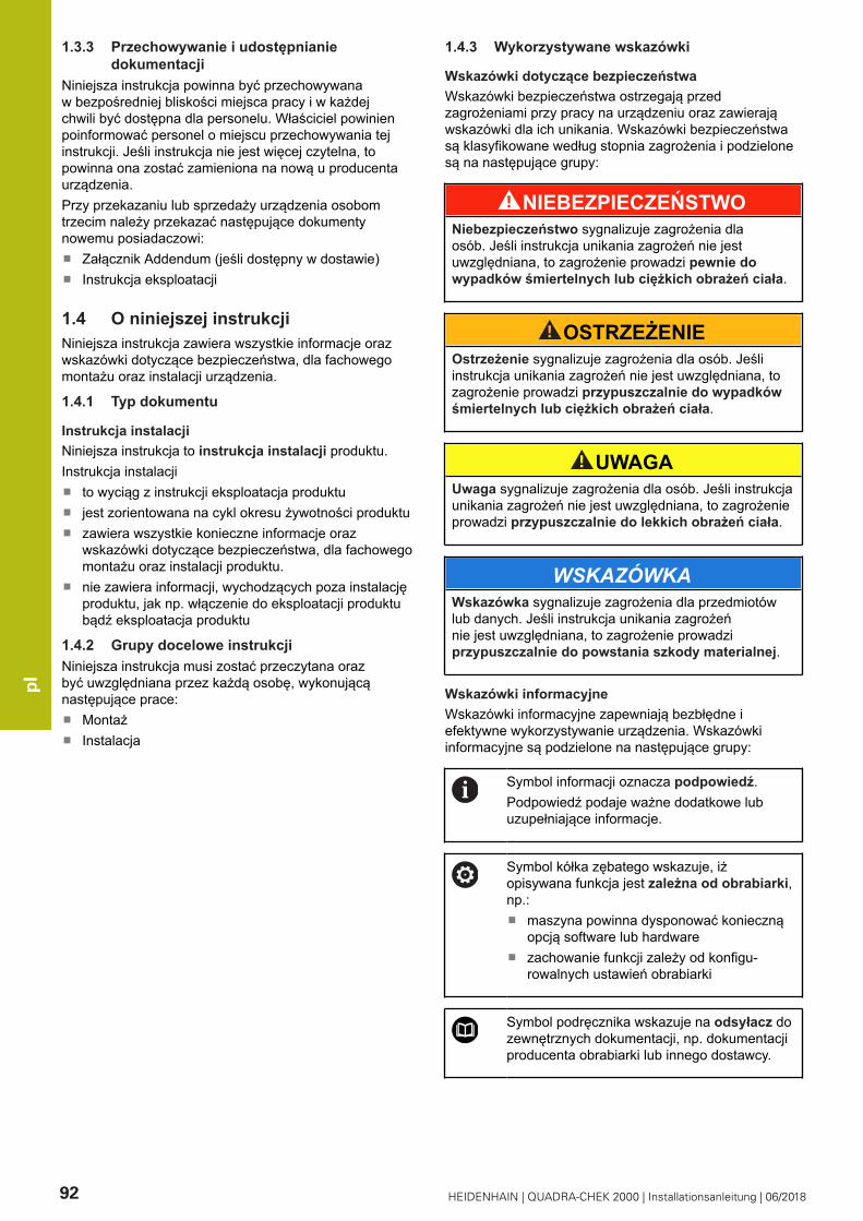
pl
92 HEIDENHAIN | QUADRA-CHEK 2000 | Installationsanleitung | 06/2018
1.3.3 Przechowywanie i udostępnianiedokumentacji
Niniejsza instrukcja powinna być przechowywanaw bezpośredniej bliskości miejsca pracy i w każdejchwili być dostępna dla personelu. Właściciel powinienpoinformować personel o miejscu przechowywania tejinstrukcji. Jeśli instrukcja nie jest więcej czytelna, topowinna ona zostać zamieniona na nową u producentaurządzenia.Przy przekazaniu lub sprzedaży urządzenia osobomtrzecim należy przekazać następujące dokumentynowemu posiadaczowi:
Załącznik Addendum (jeśli dostępny w dostawie)Instrukcja eksploatacji
1.4 O niniejszej instrukcjiNiniejsza instrukcja zawiera wszystkie informacje orazwskazówki dotyczące bezpieczeństwa, dla fachowegomontażu oraz instalacji urządzenia.
1.4.1 Typ dokumentu
Instrukcja instalacjiNiniejsza instrukcja to instrukcja instalacji produktu.Instrukcja instalacji
to wyciąg z instrukcji eksploatacja produktujest zorientowana na cykl okresu żywotności produktuzawiera wszystkie konieczne informacje orazwskazówki dotyczące bezpieczeństwa, dla fachowegomontażu oraz instalacji produktu.nie zawiera informacji, wychodzących poza instalacjęproduktu, jak np. włączenie do eksploatacji produktubądź eksploatacja produktu
1.4.2 Grupy docelowe instrukcjiNiniejsza instrukcja musi zostać przeczytana orazbyć uwzględniana przez każdą osobę, wykonującąnastępujące prace:
MontażInstalacja
1.4.3 Wykorzystywane wskazówki
Wskazówki dotyczące bezpieczeństwaWskazówki bezpieczeństwa ostrzegają przedzagrożeniami przy pracy na urządzeniu oraz zawierająwskazówki dla ich unikania. Wskazówki bezpieczeństwasą klasyfikowane według stopnia zagrożenia i podzielonesą na następujące grupy:
NIEBEZPIECZEŃSTWONiebezpieczeństwo sygnalizuje zagrożenia dlaosób. Jeśli instrukcja unikania zagrożeń nie jestuwzględniana, to zagrożenie prowadzi pewnie dowypadków śmiertelnych lub ciężkich obrażeń ciała.
OSTRZEŻENIEOstrzeżenie sygnalizuje zagrożenia dla osób. Jeśliinstrukcja unikania zagrożeń nie jest uwzględniana, tozagrożenie prowadzi przypuszczalnie do wypadkówśmiertelnych lub ciężkich obrażeń ciała.
UWAGAUwaga sygnalizuje zagrożenia dla osób. Jeśli instrukcjaunikania zagrożeń nie jest uwzględniana, to zagrożenieprowadzi przypuszczalnie do lekkich obrażeń ciała.
WSKAZÓWKAWskazówka sygnalizuje zagrożenia dla przedmiotówlub danych. Jeśli instrukcja unikania zagrożeńnie jest uwzględniana, to zagrożenie prowadziprzypuszczalnie do powstania szkody materialnej.
Wskazówki informacyjneWskazówki informacyjne zapewniają bezbłędne iefektywne wykorzystywanie urządzenia. Wskazówkiinformacyjne są podzielone na następujące grupy:
Symbol informacji oznacza podpowiedź.Podpowiedź podaje ważne dodatkowe lubuzupełniające informacje.
Symbol kółka zębatego wskazuje, iżopisywana funkcja jest zależna od obrabiarki,np.:
maszyna powinna dysponować koniecznąopcją software lub hardwarezachowanie funkcji zależy od konfigu-rowalnych ustawień obrabiarki
Symbol podręcznika wskazuje na odsyłacz dozewnętrznych dokumentacji, np. dokumentacjiproducenta obrabiarki lub innego dostawcy.

pl
HEIDENHAIN | QUADRA-CHEK 2000 | Installationsanleitung | 06/2018 93
1.4.4 Adiustacje tekstówW niniejszej instrukcji wykorzystywane są następująceadiustacje tekstów:
Ekran Znaczenie
...
...odznacza krok działania i wynik działaniaPrzykład:
Na OK kliknąćMeldunek jest zamykany
...
...odznacza wyliczeniePrzykład:
Interfejs TTLInterfejs EnDat...
tłustaczcionka
odznacza menu, wyświetlane wskazaniaoraz przyciski przełączeniowePrzykład:
Na Zamknij kliknąćSystem operacyjny zostaje zamkniętyUrządzenie wyłącznikiem głównymwyłączyć
2 Bezpieczeństwo
2.1 PrzeglądNiniejszy rozdział zawiera ważne informacje odnośniebezpieczeństwa, dla fachowego montażu oraz instalacjiurządzenia.
2.2 Ogólne środki bezpieczeństwaDla eksploatacji systemu obowiązują ogólnieprzyjęte środki bezpieczeństwa, jakie koniecznesą w szczególności w przypadku obsługi urządzeńprzewodzących prąd. Niedotrzymywanie tych przepisówmoże spowodować uszkodzenia urządzenia lub szkodydla zdrowia obsługi.Przepisy bezpieczeństwa mogą różnić się od siebiew zależności od przedsiębiorstwa. W przypadkukonfliktu pomiędzy treścią niniejszej krótkiej instrukcji iwewnętrznymi przepisami oraz zasadami obowiązującymiw danej firmie, w której eksploatowane jest to urządzenie,należy kierować się bardziej surowymi przepisamibezpieczeństwa.
2.3 Wykorzystywanie zgodnie zprzepisami
Urządzenia serii QUADRA-CHEK 2000 to znakomitacyfrowa elektronika ewaluacyjna pomiarowa do określaniaelementów konturu 2Dw aplikacjach techniki pomiarowej.Urządzenia te są stosowane w głównej mierze namaszynach pomiarowych oraz projektorach profilu.Urządzenia tej serii
mogą być eksploatowane wyłącznie w aplikacjachprzemysłowych i w sferze produkcjimuszą być montowane dla zgodnego z prze-znaczeniem wykorzystania na odpowiedniej nóżcestojakowej lub w odpowiednim uchwyciesą przewidziane do eksploatacji w zamkniętychpomieszczeniach i w otoczeniu, w którym wymogiodnośnie wilgoci, zabrudzenia, olejów i smarów sązgodne z wytycznymi zawartymi w opisie danych tech-nicznych
Urządzenia wspomagają zastosowanieznacznej ilości urządzeń peryferyjnychróżnych fabrykatów. HEIDENHAIN nieponosi odpowiedzialności za eksploatacjętych urządzeń peryferyjnych zgodnie zprzeznaczeniem. Informacje odnośniezgodnego z przeznaczeniem wykorzystaniaw przynależnych dokumentacjach muszą byćuwzględniane.

pl
94 HEIDENHAIN | QUADRA-CHEK 2000 | Installationsanleitung | 06/2018
2.4 Wykorzystywanie niezgodne zprzeznaczeniem
Niedopuszczalne dla wszystkich urządzeń serii QUADRA-CHEK 2000 są w szczególności następujące rodzajeeksploatacji:
eksploatacja i magazynowanie poza zakresemwarunków eksploatacji zgodnie z "Dane techniczne"eksploatacja na wolnym powietrzueksploatacja na obszarach zagrożonych eksplozjamiEksploatacja urządzeń serii QUADRA-CHEK 2000jako element składowy funkcji bezpieczeństwa
2.5 Kwalifikacje personeluPersonel dla montażu i instalacji musi posiadaćodpowiednie kwalifikacje dla tych prac a także byćw dostatecznym stopniu zapoznany z informacjamidokumentacji urządzenia i podłączonej peryferii.Wymogi wobec personelu, koniecznego dla wykonywaniapojedyńczych czynności na urządzeniu są podaneodpowiednich rozdziałach niniejszej instrukcji.Poniżej są dokładniej opisane grupy osób, odnośnie ichkwalifikacji oraz zadań.
Personel fachowyPersonel fachowy jest szkolony odnośnie rozszerzonejeksploatacji i obsługi oraz parametryzowania.Personel fachowy jest w stanie na podstawie swojegoprzygotowania, wiedzy i doświadczenia oraz znajomościodpowiednich uwarunkowań wykonywać zlecane zadaniawchodzące w zakres odpowiedniej aplikacji a także możesamodzielnie rozpoznawać zagrożenia i ich unikać.
Fachowiec elektrotechnikFachowiec elektrotechnik jest w stanie na podstawieswojego przygotowania, wiedzy i doświadczeniaoraz znajomości odpowiednich norm i uwarunkowańwykonywać prace na zespołach elektrycznych a takżemoże samodzielnie rozpoznawać zagrożenia i ich unikać.Fachowiec elektrotechnik jest przygotowany specjalnie dopracy w danym zakresie.Elektrotechnik musi wypełniać przepisy obowiązującegoprawa bezpieczeństwa pracy dla zapobiegania awarii iwypadków.
2.6 Obowiązki przedsiębiorcyPrzedsiębiorca znajduje się w posiadaniu urządzeniai peryferii lub dokonuje ich najmu. Jest on zawszeodpowiedzialny za przewidzianą przeznaczeniemeksploatację.Przedsiębiorca musi:
zlecać rozmaite zadania przy pracy na urządzeniuwykwalifikowanemu personelowi, posiadającemuodpowiednie przygotowanie oraz autoryzacjęSzkolić personel sprawdzalnie odnośnie kompetencji izadańUdostępnić wszelkie środki, konieczne dla personelu,do wypełnienia poleconych zadańzapewnić, iż urządzenie eksploatowane jest wyłączniew nienagannym stanie technicznymzapewnić, iż urządzenie jest zabezpieczone przedniedozwoloną eksploatacją
2.7 Ogólne wskazówki bezpieczeństwa
Odpowiedzialność za dany system, w którymużywany jest ten produkt, nosi monter lubinstalujący ten system.
Urządzenie wspomaga wykorzystywaniewielu urządzeń peryferyjnych rozmaitychproducentów. HEIDENHAIN nie ponosiodpowiedzialności za specyficzne aspektybezpieczeństwa tych urządzeń. Wskazówkidotyczące bezpieczeństwa tych urządzeńnależy zaczerpnąć z dokumentacji i jeuwzględniać. Jeśli dokumentacja nie jestdostępna, to należy uzyskać ją u producenta.
Specyficzne wskazówki odnośnie bezpieczeństwa, którenależy uwzględniać przy pojedyńczych czynnościachna urządzeniu, podane są w odpowiednich rozdziałachniniejszej instrukcji.
2.7.1 Symbole na urządzeniuUrządzenie jest odznaczone następującymi symbolami:
Symbol Znaczenie
Proszę uwzględniać wskazówki ostrzegaw-cze odnośnie elektryki i podłączenia dosieci, zanim podłączymy urządzenie.
Uziemienie funkcjonalne zgodnie zIEC/EN 60204-1. Uwzględnić wskazówkiodnośnie instalacji.
Pieczęć produktu. Jeśli pieczęć produktuzostanie naruszona, złamana lub usunięta,to wygasają warunki gwarancyjne i samagwarancja.

pl
HEIDENHAIN | QUADRA-CHEK 2000 | Installationsanleitung | 06/2018 95
2.7.2 Wskazówki bezpieczeństwa dla elektryki
OSTRZEŻENIENiebezpieczny kontakt z elementami pod napięciemprzy otwarciu urządzenia.
Elektryczny szok, porażenia lub wypadki śmiertelnemogą być skutkiem niewłaściwego otwierania.
W żadnym wypadku nie otwierać obudowyurządzeniaWszelkiego rodzaju odkrywanie obudowy musi byćdokonywane przez producenta
OSTRZEŻENIEZagrożenie niebezpiecznego przepływu przez ciałoprzy bezpośrednim lub pośrednim kontakcie zelementami pod napięciem.
Elektryczny szok, porażenia lub wypadki śmiertelnemogą być skutkiem niewłaściwego otwierania.
Prace z układami elektrycznymi i komponentamiprzewodzącymi prąd należy zlecać wyłączniewyszkolonemu fachowcowiDla złącza sieciowego oraz wszystkich innychzłącz i portów używać wyłącznie odpowiadającychnormom kabli i wtyczekDefekty elektrycznych komponentów należywymienić natychmiast komponentami producentaWszystkie podłączone kable oraz gniazdazłącz urządzenia sprawdzać regularnie. Wady,np. poluzowane złącza lub nadtopione kablenatychmiast usuwać
WSKAZÓWKAUszkodzenie wewnętrznych komponentówurządzenia!
W przypadku otwarcia urządzenia wygasają warunkigwarancyjne i sama gwarancja.
W żadnym wypadku nie otwierać obudowyurządzeniaWszelkiego rodzaju ingerencje muszą byćdokonywane przez producenta
3 Transport i magazynowanie
3.1 PrzeglądTen rozdział zawiera wszystkie informacje odnośnietransportu i magazynowania jak i zakresu dostawy orazoprzyrządowania urządzenia.
Następujące kroki mogą być przeprowadzanetylko przez wykwalifikowany personel.Dalsze informacje: "Kwalifikacje personelu",Strona 94
3.2 Wypakowanie urządzeniaOtworzyć karton na górzeUsunąć materiał pakowaniaWyjąć zawartośćSprawdzić kompletność dostawySkontrolować ewentualne szkody transportowedostawy
3.3 Zakres dostawy i akcesoria3.3.1 Zakres dostawyW dostawie zawarte są następujące artykuły:
Oznaczenie Opis
2D-demo
urządzenie
Instrukcja eksploatacji
Instrukcja instalacji
Załącznik Addendum(opcjonalnie)

pl
96 HEIDENHAIN | QUADRA-CHEK 2000 | Installationsanleitung | 06/2018
3.3.2 Oprzyrządowanie i akcesoria
Opcje software muszą być aktywowanena urządzeniu kodem licencyjnym.Przynależne komponenty hardware mogą byćwykorzystywane dopiero po odblokowaniuodpowiedniej opcji oprogramowania.
Następujące artykuły osprzętu dostępne są opcjonalnie imogą zostać zamówione w HEIDENHAIN :
Akcesoria Oznaczenie ID
do instalacji
Kabel USB 354770-xx
Wtyczka adaptera TTL 1089210-01
Wtyczka adaptera 2 Vss 1089216-01
Przełącznik nożny 681041-04
Wtyczka adaptera 11µAss
1089213-01
Wtyczka adaptera 1 Vss 1089214-01
Kabel sieciowy 223775-01
do montażu
Uchwyt Multi-Pos 1089230-08
Nóżka stojakowa Duo-Pos 1089230-06
Nóżka stojakowa Multi-Pos
1089230-07
do opcji software OED
Przewód światłowodowy 681049-xx
Łącznik przewodówświatłowodowych
681049-xx
Uchwyt 681050-xx
3.4 Jeśli stwierdzono szkodytransportowe
To należy uzyskać potwierdzenie tej szkody uspedytoraMateriały pakowania przechowywać dla zbadania.Powiadomić nadawcę o powstałych szkodachProszę skontaktować się z przedstawicielemhandlowym lub producentem odnośnie częścizamiennych
Jeśli stwierdzono szkody transportowe:Materiały pakowania przechowywać dlazbadaniaHEIDENHAIN lub producenta obrabiarkiskontaktować
Obowiązuje to także dla dostawy częścizamiennych.
3.5 Ponowne pakowanie imagazynowanie
Proszę pakować i magazynować urządzenie ostrożnie iodpowiednio do ukazanych warunków.
3.5.1 Pakowanie urządzeniaPonowne pakowanie powinno w jak największym stopniuodpowiadać oryginalnemu opakowaniu.
Wszystkie komponenty montażowe i pokrywkiprzeciwpyłowe tak umieścić na urządzeniu, jak byłyone umiejscowione przy dostawie lub tak opakować,jak były one opakowane.Tak zapakować urządzenie, aby
uderzenia i wstrząsy były tłumione przy transporciepył i wilgoć nie przenikały do opakowania
Wszystkie przesłane w dostawie części osprzętuwłożyć do opakowaniaDalsze informacje: "Zakres dostawy i akcesoria",Strona 95Całą załączoną w dostawie dokumentację włożyć doopakowaniaDalsze informacje: "Przechowywanie i udostępnianiedokumentacji", Strona 92
W przypadku przesyłek naprawczychurządzenia do serwisu:
Przesłać urządzenie bez osprzętu, bezenkoderów i bez peryferii
3.5.2 Magazynowanie urządzeniaPakować urządzenie jak to opisano powyżejUwzględnić regulacje odnośnie warunków otoczenia Dalsze informacje: "Dane techniczne", Strona 102Sprawdzać urządzenie po każdym transporcie i podłuższym magazynowaniu na uszkodzenia

pl
HEIDENHAIN | QUADRA-CHEK 2000 | Installationsanleitung | 06/2018 97
4 Montaż
4.1 PrzeglądTen rozdział opisuje montaż urządzenia. Tu znajdują sięinstrukcje, jak należy prawidłowo zamontować urządzeniena nóżkach montażowych lub w uchwytach.
Następujące kroki mogą być przeprowadzanetylko przez wykwalifikowany personel.Dalsze informacje: "Kwalifikacje personelu",Strona 94
4.2 Składanie urządzeniaOgólne wskazówki montażoweUchwyt dla wariantów montażu znajduje się w tylnejczęści urządzenia. Układ otworów montażowychodpowiada siatce 50 mm x 50 mm.Dalsze informacje: "H", Strona 175Materiał dla zamocowania wariantów montażu naurządzeniu jest dołączony do osprzętu.Dodatkowo konieczne są:
śrubokręt Torx T20śrubokręt Torx T25Klucz imbusowy SW 2,5 (nóżka stojakowa Duo-Pos)materiał do zamocowania na powierzchni ustawienia
Dla zgodnej z przeznaczeniem eksploatacjiurządzenia należy ustawić je na nóżcestojakowej lub w uchwycie.
Montaż na nóżce stojakowej Duo-PosMożna przykręcić nóżkę Duo-Pos albo pod kątemnachylenia 20° albo pod kątem 45° do urządzenia.
Jeśli nóżka stojakowa Duo-Pos zostanieprzykręcona pod kątem 45° do urządzenia,to należy zamocować urządzenie u góryw otworach montażowych. Używać kablasieciowego z wtyczką kątową.
Nóżkę zamocować dostarczonymi śrubamiimbusowymi M4 x 8 ISO 7380 w dolnych otworach zgwintem na tylnej stronie urządzenia
Uwzględnić dopuszczalny momentdokręcania wynoszący 2,6 Nm .
Przykręcić nóżkę stojakową przy pomocy szczelinmontażowych (szerokość = 4,5 mm) na powierzchniustawienia
lubUrządzenie ustawić według uznania na pożądanymmiejscuKable przeprowadzić od tyłu przez obydwie podpórkinóżki a następnie przez boczne otwory do złącz
Dalsze informacje: "C", Strona 4
Wymiarowania nóżki stojakowej Duo-PosDalsze informacje: "J", Strona 176
4.2.1 Montaż na nóżce stojakowej Multi-PosNóżkę zamocować dostarczonymi śrubamiwpuszczanymi M4 x 8 ISO 14581 (czarne) w otworachz gwintem na tylnej stronie urządzenia
Uwzględnić dopuszczalny momentdokręcania wynoszący 2,6 Nm .
Opcjonalnie można przykręcić nóżkę dwomaśrubami M5 od dołu do powierzchni ustawieniaUstawić pożądany kąt odchylenia nóżki stojakowej .Przymocować nóżkę: śrubę T25 dokręcić
Uwzględnić moment dokręcania dlaśruby T25 .
Zalecany moment dokręcania: 5,0 NmMaksymalnie dopuszczalny momentdokręcania: 15,0 Nm
Kable przeprowadzić od tyłu przez obydwie podpórkinóżki a następnie przez boczne otwory do złącz
Dalsze informacje: "D", Strona 4
Wymiarowania nóżki stojakowej Multi-PosDalsze informacje: "K", Strona 176

pl
98 HEIDENHAIN | QUADRA-CHEK 2000 | Installationsanleitung | 06/2018
4.2.2 Montaż na uchwycie Multi-PosUchwyt zamocować dostarczonymi śrubamiwpuszczanymi M4 x 8 ISO 14581 (czarne) w otworachz gwintem na tylnej stronie urządzenia
Uwzględnić dopuszczalny momentdokręcania wynoszący 2,6 Nm .
Uchwyt zamontować przy pomocy dostarczonychśrub M8, wraz z podkładkami, uchwytem inakrętką sześciokątną M8 na ramieniuUstawić pożądany kąt odchylenia nóżki stojakowej .Przymocować uchwyt: śrubę T25 dokręcić
Uwzględnić moment dokręcania dlaśruby T25 .
Zalecany moment dokręcania: 5,0 NmMaksymalnie dopuszczalny momentdokręcania: 15,0 Nm
Kable przeprowadzić od tyłu przez obydwie nóżkiuchwytu a następnie przez boczne otwory do złącz
Dalsze informacje: "E", Strona 4
Wymiarowania uchwytu Multi-PosDalsze informacje: "L", Strona 177
5 Instalacja
5.1 PrzeglądTen rozdział opisuje instalowanie urządzenia. Tu znajdująsię informacje do złącz urządzenia i instrukcje, jakpodłączyć prawidłowo urządzenia peryferyjne.
Następujące kroki mogą być przeprowadzanetylko przez wykwalifikowany personel.Dalsze informacje: "Kwalifikacje personelu",Strona 94
5.2 Ogólne wskazówki
WSKAZÓWKAZakłócenia wywoływane źródłami wysokiej emisjielektromagnetycznej!
Urządzenia peryferyjne jak przetwornice częstotliwościbądź napędy mogą powodować zakłócenia.
Aby zwiększyć niewrażliwość na zakłócenia odnośnieczynników elektromagnetycznych, należy:
wykorzystywać uziemienie funkcjonalne zgodnie zIEC/EN 60204-1Używać peryferii USB z pełnym ekranowaniem przypomocy np. folii metalowej powlekanej i plecionkimetalowej lub obudowy metalowej. Stopień pokryciaekranu plecionego musi wynosić 85 % lub więcej.Ekran musi być podłączony wokół do wtyczki(podłączenie 360°).
WSKAZÓWKATworzenie i odłączanie połączeń wtykowych!
Niebezpieczeństwo uszkodzenia wewnętrznychkomponentów.
Dokonywać połączeń i rozłączeń wtykowych tylkoprzy wyłączonym urządzeniu

pl
HEIDENHAIN | QUADRA-CHEK 2000 | Installationsanleitung | 06/2018 99
WSKAZÓWKAWyładowanie elektrostatyczne (ESD)!
Ten produkt zawiera elektrostatycznie zagrożonekomponenty, które poprzez wyładowanieelektrostatyczne mogą zostać uszkodzone.
Uwzględnić koniecznie środki bezpieczeństwa przyeksploatowaniu wrażliwych na ESD komponentówNie dotykać trzpieni złączeniowych lub pinów bezprzewidzianego uziemieniaPrzy pracach podłączeniowych na urządzeniu nosićuziemioną opaskę na nadgarstek ESD
WSKAZÓWKASzkody na urządzeniu poprzez błędne okablowanie!
Jeśli wejścia lub wyjścia zostaną błędnie okablowane,to mogą powstać szkody na urządzeniu lub peryferii.
Uwzględnić rozkład pinów i złącz oraz danetechniczne urządzeniaZajmować wyłącznie wykorzystywane piny lubsploty
Dalsze informacje: "Dane techniczne", Strona 102
5.3 Przegląd urządzeniaZłącza na tylnej stronie urządzenia są zabezpieczonepokrywkami przeciwpyłowymi przed zabrudzeniem iuszkodzeniem.
WSKAZÓWKAZabrudzenie i uszkodzenie z powodu brakującychpokrywek przeciwpyłowych!
Jeśli na niewykorzystywane złącza nie zostanąnasadzone pokrywki przeciwpyłowe, to kontakty złączmogą zostać uszkodzone bądź zniszczone.
Pokrywki przeciwpyłowe usuwać tylko wtedy,kiedy są podłączane urządzenia pomiarowe lubperyferyjneJeśli urządzenie pomiarowe lub peryferyjnezostanie usunięte, to nasadzić ponownie pokrywkęprzeciwpyłową na złącze
Rodzaje portów dla enkoderów są różne, wzależności od modelu urządzenia.
Strona tylna urządzenia bez pokrywekprzeciwpyłowychDalsze informacje: "A", Strona 4
Złącza niezależne od opcji software:2 X113: 15-biegunowe Sub-D-złącze dla przełącznika
nożnego, układów impulsowychSub-D-złącza dla enkoderów, standardowo 2 wejściaodblokowane, opcjonalnie 1 dalsze wejścia możliwedo odblokowaniaX1-X3: wariant urządzenia z 15-biegunowymi złącza-mi Sub-D dla enkoderów z 1 VSS-interfejsemX21-X23: wariant urządzenia z 9-biegunowymi Sub-D-złączami dla enkoderów z TTL-interfejsem
3
X1, X2, X21: wariant urządzenia z 15-biegunowymizłączami Sub-D dla enkoderów z 1 VSS-interfejsemi 9-biegunowym złączem Sub-D dla enkoderów zTTL-interfejsemRJ45-Ethernet-złącze4X116: złącze dla komunikacji i wymiany danych zkolejnymi systemami/PCPort USB5X32: USB 2.0 Hi-Speed-port (typ A) dla drukarki,urządzeń zapisu danych lub pamięci masowej USB
6 Uziemienie funkcjonalne zgodnie z IEC/EN 60204-17 X100: włącznik sieciowy i złącze sieciowe8 Głośniki
Złącza zależne od opcji software:Porty dla optycznego czujnika krawędziowego dookreślania punktów pomiarowychX107: wejście referencyjne dla przewodu światłowo-dowego od źródła światła
1
X108: wejście dla światłowodu od ekranu projekcyj-nego

pl
100 HEIDENHAIN | QUADRA-CHEK 2000 | Installationsanleitung | 06/2018
5.4 Podłączenie enkoderówPokrywki przeciwpyłowe zdjąć i odłożyć dlaprzechowaniaPrzeprowadzenie kabla w zależności od wariantumontażuDalsze informacje: "Składanie urządzenia", Strona 97Enkodery podłączyć do odpowiednich portów.Dalsze informacje: "Przegląd urządzenia", Strona 99Jeśli wtyki posiadają śruby: nie dociskać tych śrub zbytmocno
Rozkład złącz X1, X2, X3Dalsze informacje: "1 VSS", Strona 178
Rozkład złącz X21, X22, X23Dalsze informacje: "TTL", Strona 178
5.5 Podłączenie optycznego czujnikakrawędziowego
Pokrywki przeciwpyłowe zdjąć i odłożyć doprzechowaniaPrzeprowadzenie światłowodu w zależności odwariantu montażuDalsze informacje: "Składanie urządzenia", Strona 97
Uwzględniać informacje producentao maksymalnym kątach zagięciawykorzystywanych światłowodów
Światłowód źródła światła (referencja) w porcie X107podłączyćŚwiatłowód wychodzący od ekranu projekcyjnegopodłączyć w porcie X108
Dalsze informacje: "Przegląd urządzenia", Strona 99
Konfiguracja pinów X107, X108Dalsze informacje: "OED", Strona 178
5.6 Odrutowanie wejść i wyjśćprzełączenia
W zależności od podłączanej peryferiinależy niekiedy korzystać z wiedzy fachowejelektrotechnika, który musi dokonywać tegopodłączenia.Przykład: przekroczenie napięciabezpiecznego niskiego (SELV)Dalsze informacje: "Kwalifikacje personelu",Strona 94
Urządzenie spełnia wymogi normy IEC61010-1 tylko w przypadku, jeśli peryferia jestzasilana z obwodu wtórnego o ograniczonejmocy energii według IEC 61010-13rd Ed., punkt9.4 lub o ograniczonej wydajności wedługIEC 60950-12nd Ed., punkt 2.5 lub z obwoduwtórnego klasy 2 zgodnie z UL1310.Zamiast IEC 61010-13rd Ed., punkt 9.4 możnastosować także odpowiednie punkty normDIN EN 61010-1, EN 61010-1, UL 61010-1i CAN/CSA-C22.2 No. 61010-1 lub zamiastIEC 60950-12nd Ed., punkt 2.5 odpowiedniepunkty norm DIN EN 60950-1, EN 60950-1,UL 60950-1, CAN/CSA-C22.2 No. 60950-1.
Pokrywki przeciwpyłowe zdjąć i odłożyć dlaprzechowaniaUkładać kabel w zależności od wariantu montażu
Dalsze informacje: "Składanie urządzenia", Strona 97Kabel peryferii podłączyć do odpowiednich złączy
Dalsze informacje: "Przegląd urządzenia", Strona 99Jeśli wtyki posiadają śruby: nie dociskać tych śrub zbytmocno
Cyfrowe lub analogowe wejścia i wyjścianależy przyporządkować w ustawieniachurządzenia do odpowiedniej funkcjiprzełączenia.
Rozmieszczenie styków X 113Dalsze informacje: "X113", Strona 179
5.7 Podłączenie drukarkiDrukarkę USB podłączyć
Pokrywki przeciwpyłowe zdjąć i odłożyć dlaprzechowaniaPrzeprowadzenie kabla w zależności od wariantumontażuDalsze informacje: "Składanie urządzenia", Strona 97Drukarkę USB podłączyć do jednego z portów USB typA (X32) . Wtyczka kabla USB musi być wsunięta dokońca Dalsze informacje: "Przegląd urządzenia", Strona 99
Rozkład pinów X32Dalsze informacje: "USB", Strona 178

pl
HEIDENHAIN | QUADRA-CHEK 2000 | Installationsanleitung | 06/2018 101
Drukarkę Ethernet podłączyćPokrywki przeciwpyłowe zdjąć i odłożyć dlaprzechowaniaPrzeprowadzenie kabla w zależności od wariantumontażuDalsze informacje: "Składanie urządzenia", Strona 97Podłączyć drukarkę Ethernet przy pomocy dostępnegow handlu kabla CAT.5 do portu Ethernet X116.Wtyczka kabla musi zostać wstawiona w porcie zkliknięciemDalsze informacje: "Przegląd urządzenia", Strona 99
Rozmieszczenie styków X116Dalsze informacje: "RJ45", Strona 179
5.8 Skaner kodu kreskowego podłączyć
Można podłączyć następujące skanery kodukreskowego do urządzenia:
COGNEX DataMan 8600 (z szeregowymmodułem dla USB)
Pokrywki przeciwpyłowe zdjąć i odłożyć dlaprzechowaniaPrzeprowadzenie kabla w zależności od wariantumontażuDalsze informacje: "Składanie urządzenia", Strona 97Skaner kodu kreskowego podłączyć do portu USB typA (X32) . Wtyczka kabla USB musi być wsunięta dokońca Dalsze informacje: "Przegląd urządzenia", Strona 99
Rozkład pinów X32Dalsze informacje: "USB", Strona 178
5.9 Podłączenie urządzeń zapisu danychPokrywki przeciwpyłowe zdjąć i odłożyć dlaprzechowaniaPrzeprowadzenie kabla w zależności od wariantumontażuDalsze informacje: "Składanie urządzenia", Strona 97Myszkę USB lub klawiaturę USB podłączyć do portuUSB typ A (X32) . Wtyczka kabla USB musi byćwsunięta do końca Dalsze informacje: "Przegląd urządzenia", Strona 99
Rozkład pinów X32Dalsze informacje: "USB", Strona 178
5.10 Peryferię sieciową podłączyćPokrywki przeciwpyłowe zdjąć i odłożyć dlaprzechowaniaUkładać kabel w zależności od wariantu montażu
Dalsze informacje: "Składanie urządzenia", Strona 97Podłączyć peryferię sieciową przy pomocy dostępnegow handlu kabla CAT.5 do portu Ethernet X116.Wtyczka kabla musi zostać wstawiona w porcie zkliknięciem
Dalsze informacje: "Przegląd urządzenia", Strona 99
Rozmieszczenie styków X116Dalsze informacje: "RJ45", Strona 179
5.11 Podłączyć napięcie zasilające
OSTRZEŻENIENiebezpieczeństwo porażenia prądem!
Nieprawidłowo uziemione urządzenia mogą prowadzićdo poważnych uszkodzeń lub śmierci poprzezporażenie prądem.
Zasadniczo używać 3-żyłowego kabla sieciowegoZapewnić właściwe podłączenie przewoduochronnego do instalacji budynku
OSTRZEŻENIENiebezpieczeństwo pożaru przy zastosowaniuniewłaściwego kabla!
Zastosowanie kabli sieciowych, nie spełniającychkrajowych wymogów co do miejsca zainstalowania,może spowodować pożar.
Stosować tylko kabel sieciowy, spełniającyprzynajmniej wymogi krajowe co do jego miejscazainstalowania
Podłączenie zasilania kablem, odpowiadającymwymogom, do gniazda z przewodem ochronnym
Dalsze informacje: "Przegląd urządzenia", Strona 99
Rozmieszczenie styków X100
Dalsze informacje: "X100", Strona 178

pl
102 HEIDENHAIN | QUADRA-CHEK 2000 | Installationsanleitung | 06/2018
6 Dane techniczne
6.1 PrzeglądNiniejszy rozdział zawiera przegląd danych urządzeniaoraz rysunki z wymiarami urządzenia oraz wymiaramimontażowymi.
6.2 Dane urządzenia
Urządzenie
Korpus Aluminiowy front frezowany +żeliwna ścianka tylna
Wymiary korpusu 200 mm x 169 mm x 41 mm
Rodzajzamocowania,wymiary złącz
Układ otworów montażowych50 mm x 50 mm
Odczyt
Ekran LCD Widescreen (15:9) ekran kolorowy 17,8 cm (7")800 x 480 pikseli
Inkrementacjawskazania
nastawialna, min. 0,00001 mm
Interfej-sużytkownika
Maska użytkownika (GUI) z touch-screen
Dane elektryczne
Napięciezasilające
AC 100 V ... 240 V (±10 %)50 Hz ... 60 Hz (±5 %)Moc wejściowa max. 38 W
Bateria bufora Bateria litowa typ CR2032; 3,0 V
Kategoria-przepięcia
II
Liczbawejść-enkoderów
2 (1 dodatkowe wejście na opcjęsoftware możliwe do odblokowa-nia)
Interfejsy-enkoderów
11 μA: maksymalnenatężenie prądu 300 mA,maks. częstotliwość wejściowa 150 kHz1 VSS: maksymalnie 300 mA,max. częstotliwość wejściowa400 kHzTTL: maksymalnie 300 mA,max. częstotliwość wejściowa5 MHz
Interpolacja przy1 VSS
4096-krotnie
Złącze sondyimpulsowej
Napięcie zasilające DC 5 V lubDC 12 VWyjście przełączenia 5 V lubbezpotencjałowe4 wejścia cyfrowe1 wyjście cyfroweMaks. długość kabla zHEIDENHAIN-kablem 30 m
Dane elektryczne
Optyczny czujnikkrawędziowyport
2 F-SMA gniazda (oznaczeniegwintu 1/4-36 UNS-2A)
Wejścia cyfrowe TTL DC 0 V ... +5 V
Wyjścia cyfrowe TTL DC 0 V ... +5 VMaksymalne obciążenie 1 kΩ
Interfejsdanych 1 USB 2.0 Hi-Speed (typ A),maksymalny prąd 500 mA naport USB1 Ethernet 10/100 MBit/1 GBit(RJ45)
Otoczenie
Temperaturarobocza
0 °C ... +45 °C
Temperaturamagazynowania
-20 °C ... +70 °C
Względna wilgot-ność powietrza
10 % ... 80 % r.H. nie kondensująca
Wysokość ≤ 2000 m
Ogólne informacje
Wytyczne EMV-wytyczna 2014/30/EUWytyczna zaniżonego napięcia2014/35/EURoHS-wytyczna 2011/65/EU
Stopieńzabrudzenia
2
Stopień ochronyEN 60529
Strona przednia i boczne: IP65Strona tylna: IP40
Masa 1,3 kgz nóżką Duo-Pos: 1,45 kgz nóżką Multi-Pos: 1,95 kgz uchwytem Multi-Pos: 1,65 kg
6.3 Wymiary urządzenia i podłączeniaDalsze informacje: Strona 175 i następne strony.Wszystkie wymiary na rysunkach są podane w mm.

pt
HEIDENHAIN | QUADRA-CHEK 2000 | Installationsanleitung | 06/2018 103
1 Princípios básicos
1.1 Vista geral
Este capítulo contém informações sobre o presente
produto e as presentes instruções.
1.2 Informações sobre o produto
Designação do produto ID Índice
QUADRA-CHEK 2000 1089180-xx ---
A placa de características encontra-se na parte posterior
do aparelho.
Exemplo:
2
3
1
1 Designação do produto
2 Índice
3 Número de identidade (ID)
1.3 Documentação sobre o produto
1.3.1 Validade da documentação
Antes de a documentação e o aparelho serem utilizados,
deve-se verificar se a documentação corresponde ao
aparelho.
Comparar o número de identidade referido na
documentação e o índice com as indicações na placa
de identificação do aparelho
Se os números de identidade e os índices coincidirem,
a documentação é válida
Caso os números de identidade e os índices
não coincidam, deste modo invalidando a
documentação, encontrará a documentação
atual do aparelho em www.heidenhain.de.
1.3.2 Recomendações para a leitura da
documentação
AVISO
Acidentes de desfecho fatal, lesões ou danos
materiais em caso de inobservância da
documentação!
Se não respeitar a documentação, podem ocorrer
acidentes de desfecho fatal, lesões pessoais ou danos
materiais.
Leia atentamente a totalidade da documentação
Conserve a documentação para consultas
posteriores.
A tabela seguinte enuncia os componentes da
documentação por ordem de prioridade na leitura.
Documentação Descrição
Adenda Uma adenda completa ou substitui
os conteúdos correspondentes no
manual de instruções e, eventual-
mente, também nas instruções de
instalação.
Caso o fornecimento inclua uma
adenda, esta tem a máxima priori-
dade de leitura. Todos os restan-
tes conteúdos da documentação
mantêm a respetiva validade.
Instruções de
instalação
As instruções de instalação
contêm todas as informações e
disposições de segurança para
montar e instalar adequadamente
o aparelho. As instruções de insta-
lação fazem parte de cada forneci-
mento como excerto do manual de
instruções.
Ocupam o segundo nível de priori-
dade na leitura.
Manual de
instruções
O manual de instruções contêm
todas as informações e disposi-
ções de segurança para a utiliza-
ção adequada e conforme à finali-
dade do aparelho. O manual de
instruções está incluído no supor-
te de dados fornecido juntamente
e também pode ser transferido a
partir da secção de downloads de
www.heidenhain.de. O manual
de instruções deve ser lido antes
da colocação em funcionamento
do aparelho.
Ocupa o terceiro nível de priorida-
de na leitura.
São desejáveis alterações? Encontrou uma gralha?
Esforçamo-nos constantemente por melhorar a nossa
documentação para si. Agradecemos a sua ajuda,
informando-nos das suas propostas de alterações através
do seguinte endereço de e-mail:

pt
104 HEIDENHAIN | QUADRA-CHEK 2000 | Installationsanleitung | 06/2018
1.3.3 Conservação e transmissão da
documentação
As instruções devem ser guardadas na proximidade
imediata do local de trabalho e estar permanentemente
à disposição de todos os colaboradores. A entidade
exploradora deve informar o pessoal do local onde
estão depositadas estas instruções. Se as instruções
se tornarem ilegíveis, a entidade exploradora deve
providenciar à sua substituição pelo fabricante.
Em caso de cedência ou revenda do aparelho a terceiros,
ao novo proprietário devem ser entregues os seguintes
documentos:
Adenda (caso fornecida em conjunto)
Manual de instruções
1.4 Acerca destas instruções
Estas instruções contêm todas as informações e
disposições de segurança para montar e instalar
adequadamente o aparelho.
1.4.1 Tipo de documento
Instruções de instalação
As presentes instruções correspondem às instruções de
instalação do produto.
As instruções de instalação
são um excerto do manual de instruções do produto
orientam-se pelo ciclo de vida do produto
contêm todas as informações e disposições de
segurança necessárias para montar e instalar o
produto adequadamente e em conformidade com a
finalidade prevista
não contêm informações que fujam ao âmbito de
instalação do produto como, p. ex., a colocação em
funcionamento ou a utilização do produto
1.4.2 Grupos-alvo das instruções
As presentes instruções devem ser lidas e respeitadas
por todas as pessoas a quem seja confiado um dos
seguintes trabalhos:
Montagem
Instalação
1.4.3 Recomendações aplicadas
Disposições de segurança
As disposições de segurança alertam para os perigos
ao manusear o aparelho e dão instruções para os evitar.
As disposições de segurança classificadas segundo a
gravidade do perigo e dividem-se nos seguintes grupos:
PERIGO
Perigo assinala riscos para pessoas. Se as instruções
para evitar este risco não forem observadas, o perigo
causará certamente a morte ou lesões corporais
graves.
AVISO
Aviso assinala riscos para pessoas. Se as instruções
para evitar este risco não forem observadas, o perigo
causará provavelmente a morte ou lesões corporais
graves.
CUIDADO
Cuidado assinala riscos para pessoas. Se as instruções
para evitar este risco não forem observadas, o perigo
causará provavelmente lesões corporais ligeiras.
AVISO
Aviso assinala riscos para objetos ou dados. Se as
instruções para evitar este risco não forem observadas,
o perigo causará provavelmente um dano material.
Notas informativas
As notas informativas garantem uma utilização sem
falhas e eficiente do aparelho. As notas informativas
subdividem-se nos seguintes grupos:
O símbolo de informação representa uma
Dica.
Uma dica fornece informações importantes
adicionais ou complementares.
O símbolo da roda dentada indica que a
função descrita depende da máquina, p. ex.,
que:
A máquina deve dispor de uma opção de
software ou hardware necessária
O comportamento das funções depende
das definições configuráveis da máquina
O símbolo do livro remete para uma
referência cruzada para documentações
externas, p. ex., a documentação do fabricante
da sua máquina ou de terceiros.

pt
HEIDENHAIN | QUADRA-CHEK 2000 | Installationsanleitung | 06/2018 105
1.4.4 Marcas de texto
Nestas instruções utilizam-se as seguintes marcas de
texto:
Representação Significado
...
...
caracteriza um passo de operação e
o resultado de uma operação
Exemplo:
Tocar em OKFecha-se a mensagem
...
...
caracteriza uma enumeração
Exemplo:
Interface TTL
Interface EnDat
...
Negrito identifica menus, visualizações e
botões do ecrã
Exemplo:
Tocar em EncerrarO sistema operativo é encerrado
Desligar o aparelho no interruptor
de rede
2 Segurança
2.1 Vista geral
Este capítulo contém informações importantes
sobre segurança, para montar e instalar o aparelho
adequadamente.
2.2 Procedimentos de segurança gerais
Para a utilização do sistema são aplicáveis todos os
procedimentos de segurança geralmente aceites,
em especial, os requeridos no manuseamento de
aparelhos condutores de corrente. A inobservância destas
precauções de segurança pode ter provocado danos no
aparelho ou lesões.
As precauções de segurança podem variar de empresa
para empresa. Em caso de conflito entre o conteúdo
deste guia rápido e os regulamentos internos de uma
empresa, na qual este aparelho seja utilizado, aplicar-se-ão
as regras mais rigorosas.
2.3 Utilização conforme à finalidade
Os aparelhos da série QUADRA-CHEK 2000 são
sistemas eletrónicos de avaliação digital de alta qualidade
destinados à leitura de elementos de contorno 2D em
aplicações de metrologia. Os aparelhos são utilizados,
principalmente, em máquinas de medição e projetores de
perfis.
Os aparelhos desta série
só podem ser utilizados em aplicações comerciais e
em ambiente industrial
devem ser montados num pedestal ou suporte
apropriado para uma utilização conforme à finalidade
prevista
destinam-se à utilização em interiores e num ambiente
em que a carga de humidade, sujidade, óleo e lubri-
ficantes cumpre as prescrições nos dados técnicos
Os aparelhos suportam a utilização de
aparelhos periféricos de diferentes fabricantes.
A HEIDENHAIN não pode prestar qualquer
informação sobre a utilização conforme à
finalidade específica destes aparelhos. Devem
respeitar-se as informações sobre a utilização
conforme à finalidade incluídas nas respetivas
documentações.

pt
106 HEIDENHAIN | QUADRA-CHEK 2000 | Installationsanleitung | 06/2018
2.4 Utilização não conforme à finalidade
Não são admissíveis para todos os aparelhos da série
QUADRA-CHEK 2000, em particular, as seguintes
aplicações:
Utilização e armazenagem fora das condições de
utilização descritas nos "Dados técnicos"
Utilização ao ar livre
Utilização em áreas potencialmente explosivas
Utilização dos aparelhos da série QUADRA-CHEK 2000
como componentes de uma função de segurança
2.5 Qualificação do pessoal
O pessoal responsável pela montagem e instalação deve
possuir a qualificação necessária para estes trabalhos
e estar suficientemente informado com o apoio da
documentação do aparelho e dos periféricos conectados.
Os requisitos do pessoal necessários para as várias
atividades no aparelho são indicados nos capítulos
correspondentes destas instruções.
Especificam-se seguidamente os grupos de pessoas em
relação às suas qualificações e tarefas.
Pessoal especializado
O pessoal especializado recebe formação por parte da
entidade exploradora para o comando avançado e a
parametrização. Devido à sua formação, conhecimentos
e experiência profissionais, bem como ao conhecimento
das disposições relevantes, o pessoal especializado
está em condições de executar os trabalhos que lhe
são confiados relativamente à respetiva aplicação e de
reconhecer e evitar autonomamente potenciais perigos.
Eletricista
Devido à sua formação, conhecimentos e experiência
profissionais, bem como ao conhecimento das normas e
disposições relevantes, o eletricista está em condições
de executar trabalhos em instalações elétricas e de
reconhecer e evitar autonomamente potenciais perigos.
O eletricista tem formação específica para o ambiente de
trabalho em que desenvolve a sua atividade.
O eletricista deve cumprir os requisitos das normas legais
de prevenção de acidentes em vigor.
2.6 Obrigações da entidade exploradora
A entidade exploradora possui ou alugou o aparelho e os
periféricos. É sempre responsável pela respetiva utilização
conforme à finalidade.
A entidade exploradora deve:
atribuir as diferentes tarefas a pessoal qualificado,
idóneo e autorizado
formar comprovadamente o pessoal para as
atribuições e tarefas
colocar à disposição do pessoal todos os meios de que
necessite para cumprir as tarefas que sejam atribuídas
assegurar-se de que o aparelho é utilizado apenas se
estiver em perfeitas condições técnicas
assegurar-se de que o aparelho é protegido contra uma
utilização não autorizada
2.7 Disposições de segurança gerais
A responsabilidade por cada sistema que seja
utilizado neste produto cabe ao técnico de
montagem ou instalação desse sistema.
O aparelho suporta a utilização de múltiplos
aparelhos periféricos de diferentes fabricantes.
A HEIDENHAIN não pode prestar qualquer
informação sobre as disposições de
segurança específicas destes aparelhos.
Devem respeitar-se as disposições de
segurança incluídas nas documentações
correspondentes. Caso as documentações
não estejam disponíveis, devem ser
solicitadas aos fabricantes.
As disposições de segurança específicas para as várias
atividades no aparelho são indicadas nos capítulos
correspondentes destas instruções.
2.7.1 Símbolos no aparelho
No aparelho encontram-se os seguintes símbolos:
Símbolo Significado
Respeite as disposições de segurança para
o sistema elétrico e a ligação à rede antes
de ligar o aparelho.
Ligação para a função de ligação a terra
conforme a IEC/EN 60204-1. Preste
atenção às recomendações de instalação.
Selo do produto. Se o selo do produto
estiver quebrado ou tiver sido removido,
a garantia legal e do fabricante perdem a
validade.

pt
HEIDENHAIN | QUADRA-CHEK 2000 | Installationsanleitung | 06/2018 107
2.7.2 Disposições de segurança para o sistema
elétrico
AVISO
Contacto perigoso com partes condutoras de
tensão ao abrir o aparelho.
Pode ter como consequência um choque elétrico,
queimaduras ou a morte.
Não abrir a caixa em caso algum
Mandar proceder a intervenções apenas pelo
fabricante
AVISO
Perigo de eletrocussão perigosa em caso de
contacto direto ou indireto com partes condutoras
de tensão
Pode ter como consequência um choque elétrico,
queimaduras ou a morte.
Mandar executar os trabalhos no sistema elétrico e
nos componentes condutores de corrente apenas a
um especialista com formação
Utilizar exclusivamente cabos e conectores
normalizados para a ligação à corrente e todas as
ligações de interface
Mandar substituir os componentes elétricos
avariados imediatamente através do fabricante
Verificar regularmente todos os cabos ligados
e tomadas de ligação do aparelho. Eliminar
imediatamente as deficiências, por exemplo,
ligações soltas ou cabos queimados
AVISO
Danos em componentes internos do aparelho!
Caso o aparelho seja aberto, a garantia legal e do
fabricante perdem a validade.
Não abrir a caixa em caso algum
Mandar proceder a intervenções apenas pelo
fabricante do aparelho
3 Transporte e armazenamento
3.1 Vista geral
Este capítulo contém informações sobre o transporte
e armazenamento, assim como sobre o volume de
fornecimento e acessórios do aparelho.
Os passos seguintes podem ser executados
apenas por pessoal especializado.
Mais informações: "Qualificação do pessoal",
Página 106
3.2 Desembalar o aparelho
Abrir a embalagem de cartão pela parte de cima
Remover o material de embalagem
Retirar o conteúdo
Verificar a integridade do fornecimento
Controlar se o fornecimento apresenta danos de
transporte
3.3 Volume de fornecimento e
acessórios
3.3.1 Volume de fornecimento
O fornecimento inclui os seguintes artigos:
Designação Descrição
Peça de demonstração em
2D
Aparelho
Manual de instruções
Instruções de instalação
Adenda (opcional)

pt
108 HEIDENHAIN | QUADRA-CHEK 2000 | Installationsanleitung | 06/2018
3.3.2 Acessórios
As opções de software devem ser ativadas no
aparelho mediante um código de licença. Os
componentes de hardware correspondentes
só podem ser utilizados após a ativação da
opção de software respetiva.
Os acessórios enumerados abaixo podem ser
encomendados opcionalmente à HEIDENHAIN:
Acessórios Designação ID
para a instalação
Conector adaptador 11
µAss
1089213-01
Cabo elétrico 223775-01
Conector adaptador 1 Vss 1089214-01
Cabo de ligação USB 354770-xx
Conector adaptador 2 Vss 1089216-01
Conector adaptador TTL 1089210-01
Botão de pé 681041-04
para a montagem
Pedestal Duo-Pos 1089230-06
Pedestal Multi-Pos 1089230-07
Suporte Multi-Pos 1089230-08
da opção de software OED
Cabo de fibra ótica 681049-xx
Ligação de cabo de fibra
ótica
681049-xx
Ajustar 681050-xx
3.4 Quando exista um dano de
transporte
Mandar confirmar o dano pelo transportador
Reservar os materiais de embalagem para serem
examinados
Dar conhecimento dos danos ao remetente
Contactar o distribuidor ou o fabricante da máquina
para peças sobresselentes
Em caso de dano de transporte:
Guardar os materiais de embalagem para
serem examinados
Contactar a HEIDENHAIN ou o fabricante
da máquina
Esta recomendação aplica-se igualmente a
danos de transporte em pedidos de peças
sobresselentes.
3.5 Reembalamento e armazenamento
Embale e armazene o aparelho cautelosamente e de
acordo com as condições aqui mencionadas.
3.5.1 Embalar o aparelho
Tanto quanto possível, o reembalamento deverá
corresponder à embalagem original.
Colocar todos os componentes e tampas de proteção
anti pó no aparelho conforme estavam aplicados no
fornecimento do aparelho ou embalá-los novamente
conforme estavam embalados.
Embalar o aparelho de modo a
amortecer quaisquer impactos e vibrações durante
o transporte
que não possa penetrar pó nem humidade
Colocar na embalagem todos os acessórios fornecidos
juntamente
Mais informações: "Volume de fornecimento e
acessórios", Página 107
Juntar toda a documentação recebida no fornecimento
Mais informações: "Conservação e transmissão da
documentação", Página 104
Nos casos de devolução do aparelho para
reparação pelo serviço de assistência técnica:
Enviar o aparelho sem acessórios, sem
encoders e sem aparelhos periféricos
3.5.2 Armazenar o aparelho
Embalar o aparelho conforme descrito acima
Respeitar as disposições para as condições ambientais
Mais informações: "Dados técnicos", Página 114
Após cada transporte e após um armazenamento
prolongado, verificar se o aparelho está danificado

pt
HEIDENHAIN | QUADRA-CHEK 2000 | Installationsanleitung | 06/2018 109
4 Montagem
4.1 Vista geral
Este capítulo descreve a montagem do aparelho. Encontra
aqui recomendações sobre como montar corretamente o
aparelho nos pedestais ou suportes.
Os passos seguintes podem ser executados
apenas por pessoal especializado.
Mais informações: "Qualificação do pessoal",
Página 106
4.2 Montagem do aparelho
Instruções de montagem gerais
O encaixe para as variantes de montagem encontra-se na
parte posterior do aparelho. O padrão de furos de fixação
corresponde a uma grelha de 50 mm x 50 mm.
Mais informações: "H", Página 175
O material para fixação das variantes de montagem no
aparelho é fornecido juntamente com os acessórios.
Necessitará, adicionalmente, dos seguintes artigos:
Chave de parafusos Torx T20
Chave de parafusos Torx T25
Chave Allen, abertura 2,5 (pedestal Duo-Pos)
Material para a fixação numa superfície de apoio
Para uma utilização conforme à finalidade, o
aparelho deve estar montado num pedestal ou
num suporte.
Montagem no pedestal Duo-Pos
O pedestal Duo-Pos pode ser aparafusado ao aparelho
com uma inclinação de 20° ou com uma inclinação de 45°.
Se o pedestal Duo-Pos for aparafusado
ao aparelho com uma inclinação de 45°, é
necessário fixar o aparelho na extremidade
superior da ranhura de montagem. Utilize um
cabo elétrico com conector angular.
Fixar o pedestal aos furos roscados inferiores na parte
posterior do aparelho com os parafusos sextavados
internos M4 x 8 ISO 7380 fornecidos juntamente
Respeitar o binário de aperto admissível
de 2,6 Nm
Aparafusar o pedestal a uma superfície de apoio
através da ranhura de montagem (largura = 4,5 mm)
ou
Colocar o aparelho livremente na localização desejada
Instalar os cabos pela parte de trás através das duas
aberturas do pedestal e levá-los até às ligações,
passando-os pelas aberturas laterais.
Mais informações: "C", Página 4
Dimensões do pé de suporte Duo-Pos
Mais informações: "J", Página 176
4.2.1 Montagem no pedestal Multi-Pos
Fixar o pedestal aos furos roscados na parte posterior
do aparelho com os parafusos de cabeça escareada
M4 x 8 ISO 14581 (pretos) fornecidos juntamente
Respeitar o binário de aperto admissível
de 2,6 Nm
Opcionalmente, aparafusar o pedestal pela parte
de baixo a uma superfície de apoio com dois
parafusos M5
Ajustar o ângulo de inclinação desejado
Fixar o pedestal: apertar bem o parafuso T25
Respeitar o binário de aperto para o
parafuso T25
Binário de aperto recomendado: 0,5 Nm
Binário de aperto máximo admissível:
15,0 Nm.
Instalar os cabos pela parte de trás através das duas
aberturas do pedestal e levá-los até às ligações,
passando-os pelas aberturas laterais.
Mais informações: "D", Página 4
Dimensões do pé de suporte Multi-Pos
Mais informações: "K", Página 176

pt
110 HEIDENHAIN | QUADRA-CHEK 2000 | Installationsanleitung | 06/2018
4.2.2 Montagem no suporte Multi-Pos
Fixar o suporte aos furos roscados na parte posterior
do aparelho com os parafusos de cabeça escareada
M4 x 8 ISO 14581 (pretos) fornecidos juntamente
Respeitar o binário de aperto admissível
de 2,6 Nm
Montar o suporte num braço com o parafuso M8, as
arruelas, o punho e a porca sextavada M8 fornecidos
juntamente
Ajustar o ângulo de inclinação desejado
Fixar o suporte: apertar bem o parafuso T25
Respeitar o binário de aperto para o
parafuso T25
Binário de aperto recomendado: 0,5 Nm
Binário de aperto máximo admissível:
15,0 Nm.
Instalar os cabos pela parte de trás através das
duas aberturas do suporte e levá-los até às ligações,
passando-os pelas aberturas laterais.
Mais informações: "E", Página 4
Dimensões do suporte Multi-Pos
Mais informações: "L", Página 177
5 Instalação
5.1 Vista geral
Este capítulo descreve a Instalação do aparelho. Encontra
aqui informações sobre as ligações do aparelho e
instruções sobre como conectar corretamente os
aparelhos periféricos.
Os passos seguintes podem ser executados
apenas por pessoal especializado.
Mais informações: "Qualificação do pessoal",
Página 106
5.2 Avisos gerais
AVISO
Avarias devido a fontes de emissão altamente
eletromagnética!
Aparelhos periféricos como conversores de frequência
ou acionamentos podem causar anomalias.
Para aumentar a insensibilidade a interferências
eletromagnéticas:
Utilizar a ligação opcional conforme a IEC/EN
60204-1 para a função de ligação a terra
Utilizar apenas periféricos USB com blindagem
contínua mediante, p. ex., folha metalizada e malha
metálica ou caixa metálica. O grau de cobertura da
malha de blindagem deve ser de 85% ou mais. A
blindagem deve estar completamente integrada no
conector (conexão de 360 º)
AVISO
Executar e soltar conectores!
Perigo de danos em componentes internos.
Executar ou soltar os conectores apenas com o
aparelho desligado

pt
HEIDENHAIN | QUADRA-CHEK 2000 | Installationsanleitung | 06/2018 111
AVISO
Descarga eletrostática (ESD)!
O aparelho contém componentes sujeitos ao perigo
de descarga eletrostática que podem ser destruídos
devido a uma descarga eletrostática (ESD).
Respeitar escrupulosamente os procedimentos de
segurança para manuseamento de componentes
sensíveis a ESD
Nunca tocar nos pinos de ligação sem que haja uma
ligação a terra correta
Usar uma pulseira ESD ligada a terra ao efetuar
trabalhos nas ligações dos aparelhos
AVISO
Danos no aparelho devido a cablagem incorreta!
Se ligar os cabos das entradas ou saídas
incorretamente, podem ocorrer danos no aparelho ou
nos aparelhos periféricos.
Respeitar as atribuições das ligações e os dados
técnicos do aparelho
Ocupar exclusivamente os pinos ou condutores
utilizados
Mais informações: "Dados técnicos", Página 114
5.3 Vista geral do aparelho
As ligações na parte posterior do aparelho são protegidas
contra a sujidade e danos mediante tampas de proteção
anti pó.
AVISO
Sujidade e danos devido à falta de tampas de
proteção anti pó!
Se não colocar tampas de proteção anti pó nas ligações
não utilizadas, o funcionamento dos contactos de
ligação pode ser prejudicado ou impedido.
Remover as tampas de proteção anti pó apenas
quando se liguem aparelhos de medição ou
periféricos
Se um aparelho de medição ou um periférico forem
removidos, colocar novamente a tampa de proteção
anti pó sobre a ligação
O tipo das ligações para aparelhos de medição
pode variar consoante a versão do aparelho.
Parte posterior do aparelho sem tampas de proteção
anti pó
Mais informações: "A", Página 4
Ligações independentes das opções de software:
2 X113: ligação Sub-D de 15 pinos para botões de pé,
apalpadores
Ligações Sub-D para encoders, por norma, com 2
entradas ativadas, 1 outra entrada ativável opcional-
mente
X1-X3: variante de aparelho com ligações Sub-D de
15 pinos para encoders com interface 1 VSS
X21-X23: variante de aparelho com ligações Sub-D
de 9 pinos para encoders com interface TTL
3
X1, X2, X21: variante de aparelho com duas ligações
Sub-D de 15 pinos para encoders com interface 1 VSS
e uma ligação Sub-D de 9 pinos para encoders com
interface TTL
Ligação de Ethernet RJ454
X116: ligação para comunicação e troca de dados
com sistemas subsequentes ou PC
Ligação USB5
X32: ligação USB 2.0 Hi-Speed (tipo A) para impres-
soras, dispositivos de entrada ou dispositivos USB de
armazenamento em massa
6 Ligação para a função de ligação a terra conforme a
IEC/EN 60204-1
7 X100: interruptor de rede e ligação à corrente
8 Altifalantes
Ligações dependentes das opções de software:
Ligações para o sensor ótico de arestas para registo
de pontos de medição
1
X107: entrada de referência para o cabo de fibra ótica
proveniente da fonte de luz

pt
112 HEIDENHAIN | QUADRA-CHEK 2000 | Installationsanleitung | 06/2018
X108: entrada para o cabo de fibra ótica proveniente
do ecrã de projeção
5.4 Ligação dos aparelhos de medição
Remover e guardar as tampas de proteção anti pó
Instalar os cabos consoante a variante de montagem
Mais informações: "Montagem do aparelho",
Página 109
Conectar os aparelhos de medição solidamente às
respetivas ligações
Mais informações: "Vista geral do aparelho",
Página 111
Tratando-se de fichas com parafusos: não apertar
demasiadamente os parafusos
Atribuição de ligação X1, X2, X3
Mais informações: "1 VSS", Página 178
Atribuição de ligação X21, X22, X23
Mais informações: "TTL", Página 178
5.5 Ligação do sensor ótico de arestas
Remover e guardar as tampas de proteção anti pó
Instalar os cabos de fibra ótica consoante a variante de
montagem
Mais informações: "Montagem do aparelho",
Página 109
Respeitar as recomendações do
fabricante para o raio de curvatura
máximo dos cabos de fibra ótica
Conectar o cabo de fibra ótica da fonte de luz
(referência) à ligação X107
Conectar o cabo de fibra ótica proveniente do ecrã de
projeção à ligação X108
Mais informações: "Vista geral do aparelho",
Página 111
Atribuição de ligação X107, X108
Mais informações: "OED", Página 178
5.6 Cablagem das entradas e saídas de
comutação
Dependendo dos periféricos a conectar,
as atividades de ligação poderão exigir a
presença de um eletricista.
Exemplo: tensão reduzida de segurança (SELV)
excedida
Mais informações: "Qualificação do pessoal",
Página 106
O aparelho cumpre os requisitos da Norma
IEC 61010-1 apenas se os periféricos forem
alimentados a partir de um circuito secundário
com energia limitada conforme a IEC
61010-13.ª Ed., Secção 9.4 ou com potência
limitada conforme a IEC 60950-12.ª Ed., Secção
2.5 ou a partir de um circuito secundário da
Classe 2 conforme a UL1310.
Em lugar da IEC 61010-13.ª Ed., Secção 9.4,
também podem ser aplicadas as secções
correspondentes das Normas DIN EN 61010-1,
EN 61010-1, UL 61010-1 e CAN/CSA-C22.2
N.º 61010-1 ou, em lugar da IEC 60950-12.ª
Ed., Secção 2.5, as secções correspondentes
das Normas DIN EN 60950-1, EN 60950-1, UL
60950-1, CAN/CSA-C22.2 N.º 60950-1.
Remover e guardar as tampas de proteção anti pó
Instalar os cabos consoante a variante de montagem
Mais informações: "Montagem do aparelho", Página 109
Conectar os cabos de ligação dos aparelhos periféricos
solidamente às respetivas ligações
Mais informações: "Vista geral do aparelho",
Página 111
Tratando-se de fichas com parafusos: não apertar
demasiadamente os parafusos
As entradas e saídas digitais ou analógicas
devem ser atribuídas à respetiva função de
comutação nas definições do aparelho.
Atribuição da ligação X 113
Mais informações: "X113", Página 179
5.7 Ligação da impressora
Ligação da impressora USB
Remover e guardar as tampas de proteção anti pó
Kabel je nach Montagevariante verlegen
Mais informações: "Montagem do aparelho",
Página 109
Conectar a impressora USB à ligação USB tipo A (X32).
O conector USB do cabo deve ficar completamente
inserido
Mais informações: "Vista geral do aparelho",
Página 111
Atribuição de ligação X32
Mais informações: "USB", Página 178

pt
HEIDENHAIN | QUADRA-CHEK 2000 | Installationsanleitung | 06/2018 113
Ligar a impressora Ethernet
Remover e guardar as tampas de proteção anti pó
Kabel je nach Montagevariante verlegen
Mais informações: "Montagem do aparelho",
Página 109
Ethernet-Drucker mit Hilfe eines handelsüblichen
CAT.5-Kabels an Ethernet-Anschluss X116 anschließen.
Der Kabelstecker muss fest im Anschluss einrasten
Mais informações: "Vista geral do aparelho",
Página 111
Atribuição da ligação X116
Mais informações: "RJ45", Página 179
5.8 Ligação do leitor de códigos de
barras
Pode ligar o seguinte leitor de códigos de
barras ao aparelho:
COGNEX DataMan 8600 (com módulo
serial para USB)
Remover e guardar as tampas de proteção anti pó
Instalar os cabos consoante a variante de montagem
Mais informações: "Montagem do aparelho",
Página 109
Conectar o leitor de códigos de barras à ligação USB
tipo A (X32). O conector USB do cabo deve ficar
completamente inserido
Mais informações: "Vista geral do aparelho",
Página 111
Atribuição de ligação X32
Mais informações: "USB", Página 178
5.9 Ligação de dispositivos de entrada
Remover e guardar as tampas de proteção anti pó
Instalar os cabos consoante a variante de montagem
Mais informações: "Montagem do aparelho",
Página 109
Conectar o rato USB ou teclado USB à ligação USB
tipo A (X32). O conector USB do cabo deve ficar
completamente inserido
Mais informações: "Vista geral do aparelho",
Página 111
Atribuição de ligação X32
Mais informações: "USB", Página 178
5.10 Ligar os periféricos de rede
Remover e guardar as tampas de proteção anti pó
Instalar os cabos consoante a variante de montagem
Mais informações: "Montagem do aparelho", Página 109
Conectar os periféricos de rede à ligação Ethernet
X116 mediante um cabo CAT.5 convencional. A ficha do
cabo deve encaixar solidamente na ligação
Mais informações: "Vista geral do aparelho", Página 111
Atribuição da ligação X116
Mais informações: "RJ45", Página 179
5.11 Ligar a tensão de rede
AVISO
Perigo de choque elétrico!
Aparelhos incorretamente ligados a terra podem causar
lesões graves ou a morte por choque elétrico.
Por princípio, utilizar um cabo elétrico de 3 pinos
Assegurar a correta ligação do condutor de proteção
à instalação do edifício
AVISO
Perigo de incêndio devido ao cabo elétrico
incorreto!
A utilização de um cabo elétrico que não cumpra os
requisitos nacionais no local de implantação pode
causar perigo de incêndio.
Utilizar apenas um cabo elétrico que cumpra,
no mínimo, os requisitos nacionais no local de
implantação
Conectar a ligação à corrente com um cabo elétrico
que corresponda aos requisitos à tomada com
condutor de proteção
Mais informações: "Vista geral do aparelho", Página 111
Atribuição da ligação X100
Mais informações: "X100", Página 178

pt
114 HEIDENHAIN | QUADRA-CHEK 2000 | Installationsanleitung | 06/2018
6 Dados técnicos
6.1 Vista geral
Este capítulo inclui um resumo dos dados do aparelho e
desenhos com os dados do aparelho e de implantação.
6.2 Dados do aparelho
Aparelho
Caixa Painel frontal em alumínio + parede
posterior fundida
Dimensões da
caixa
200 mm x 169 mm x 41 mm
Tipo de fixação,
Dimensões de
implantação
Padrão de furos de fixação
50 mm x 50 mm
Mostrar
Ecrã LCD Widescreen (15: 9)
Ecrã a cores 17,8 cm (7")
800 x 480 pixel
Resolução ajustável, mín. 0,00001 mm
Interface
de utilizador
Interface do utilizador (GUI) com
Touchscreen
Dados elétricos
Tensão de
alimentação
AC 100 V ... 240 V (±10 %)
50 Hz ... 60 Hz (±5 %)
Potência de entrada máx. 38 W
Acumulador Bateria de lítio tipo CR2032; 3,0 V
Categoria de
sobretensão
Ii
Quantidade
de entradas
de aparelhos de
medição
2 (1 entrada adicional ativável por
opção de software)
Interfaces
de encoders
11μA: corrente máxima 300 mA,
frequência de entrada máx.
150 kHz
1 VSS: corrente máxima 300 mA,
frequência de entrada máx.
400 kHz
TTL: corrente máxima 300 mA,
requência de entrada máx. 5 MHz
Interpolação
com 1 VSS
4096 vezes
Ligação de
apalpadores
Alimentação de tensão DC 5 V
ou DC 12 V
Saída de comutação de 5 V ou
sem potencial
4 entradas digitais
1 saída digital
Comprimento máx. de cabo com
cabo HEIDENHAIN: 30 m
Dados elétricos
Ligação
do sensor
ótico de arestas
2 tomadas F-SMA (designação da
rosca 1/4-36 UNS-2A)
Entradas digitais TTL DC 0 V ... +5 V
Saídas digitais TTL DC 0 V ... +5 V
Carga máxima 1 kΩ
Interface
de dados
1 USB 2.0 Hi-Speed (Tipo A),
corrente máxima 500 mA por
ligação USB
1 Ethernet 10/100 MBit/1 GBit
(RJ45)
Ambiente
Temperatura de
funcionamento
0 °C ... +45 °C
Temperatura de
armazenagem
-20 °C ... +70 °C
Humidade
relativa do ar
10 % ... 80 % h.r. não condensante
Altura ≤ 2000 m
Geral
Diretivas Diretiva "CEM" 2014/30/UE
Diretiva "Baixa Tensão" 2014/35/UE
Diretiva RoHS 2011/65/UE
Grau de
contaminação
2
Classe de prote-
ção EN 60529
Frente e lados: IP65
Parte posterior: IP40
Massa 1,3 kg
com pedestal Duo-Pos: 1,45 kg
com pedestal Multi-Pos: 1,95 kg
com suporte Multi-Pos: 1,65 kg
6.3 Dimensões do aparelho e de
implantação
Mais informações: Página 175 e páginas seguintes.
Todas as dimensões nos desenhos são indicadas em
milímetros.

tr
HEIDENHAIN | QUADRA-CHEK 2000 | Installationsanleitung | 06/2018 115
1 Temel bilgiler
1.1 Genel bakışBu bölümde, sahip olduğunuz ürün ile ilgili bilgiler veürüne ait kılavuz yer almaktadır.
1.2 Ürün ile ilgili bilgiler
Ürün tanımı Kimlik Endeks
QUADRA-CHEK 2000 1089180-xx ---
Tip levhası cihazın arka tarafında bulunur.Örnek:
2
3
1
1 Ürün tanımı2 İndeks3 Tanım numarası (kimlik)
1.3 Ürün dokümantasyonu1.3.1 Dokümantasyonun geçerliliğiDokümantasyonu ve cihazı kullanmadan öncedokümantasyonun cihaz ile uyuşup uyuşmadığını kontroledin.
Dokümantasyonda belirtilen tanım numarası veindeksi, cihazın tip levhasındaki bilgilerle karşılaştırınTanım numaraları ve indeksler uyuşuyorsadokümantasyon geçerlidir
Tanım numaraları ve indeksler uyuşmuyorsave bu nedenle dokümantasyon geçerlideğilse cihaza ait güncel dokümantasyonuwww.heidenhain.de adresinde bulabilirsiniz.
1.3.2 Dokümantasyonun okunmasına ilişkinbilgiler
UYARIDokümantasyonun dikkate alınmaması ölümcülkazalara, yaralanmalara veya maddi hasara yolaçabilir!
Dokümantasyonun dikkate alınmaması ölümcülkazalara, kişilerin yaralanmasına veya maddi hasarayol açabilir.
Dokümantasyonun tamamını dikkatlice okuyunDokümantasyonu sonraki kullanımlar için saklayın
Aşağıdaki tabloda dokümantasyonun bölümleri okunmaönceliklerine göre listelenmiştir.
Dokümantasyon Açıklama
Ek Bir Ek, işletim kılavuzunda vegerekliyse kurulum kılavuzunda yeralan ilgili içeriklere yönelik tamam-layıcı bilgiler içerir veya bunlarınyerine geçer.Ek belgesi teslimat kapsamınadahil edilmişse okunması gerekenbelgeler arasında en yüksekönceliğe sahiptir. Dokümantasyo-nun diğer tüm içeriklerin geçerliliğikorunur.
Kurulum kılavuzu İşbu kurulum kılavuzu, cihazınusulüne uygun olarak monteedilmesi ve kurulması için gerekliolan tüm bilgileri ve güvenlik uyarı-larını içermektedir. İşletim kılavu-zundan bir alıntı olan kurulumkılavuzu tüm teslimatların kapsa-mında yer alır.Kurulum kılavuzu okunmasıgereken belgeler arasında ikinciönceliğe sahiptir.
İşletim kılavuzu İşbu işletim kılavuzu, cihazınusulüne amacına uygun kullanı-mı için gerekli olan tüm bilgilerive güvenlik uyarılarını içermekte-dir. İşletim kılavuzu, cihaz ile birlik-te teslim edilen bellek ortamındayer alır ve www.heidenhain.deadresindeki indirme alanından daindirilebilir. Cihaz işletime alınma-dan önce işletim kılavuzu okunma-lıdır.İşletim kılavuzu okunması gerekenbelgeler arasında üçüncü önceliğesahiptir.
Değişiklikler isteniyor mu ya da hata kaynağı mıbulundu?Dokümantasyon alanında kendimizi sizin için sürekliiyileştirme gayreti içindeyiz. Bize bu konuda yardımcıolun ve değişiklik isteklerinizi lütfen aşağıdaki e-postaadresinden bizimle paylaşın:[email protected]

tr
116 HEIDENHAIN | QUADRA-CHEK 2000 | Installationsanleitung | 06/2018
1.3.3 Dokümantasyonun saklanması vedevredilmesi
Kılavuz, çalışma yerinin yakınında muhafaza edilmelive her zaman tüm personelin kullanımına hazırbulundurulmalıdır. İşletmeci, personelini bu kılavuzunsaklama yeri ile ilgili bilgilendirmelidir. Kılavuzunokunamayacak hale gelmesi durumunda işletmecitarafından üreticiden bir yedek istenmelidir.Cihazın üçüncü kişilere devredilmesi veya satılmasıdurumunda aşağıdaki belgelerin yeni sahiplerinedevredilmesi gerekir:
Ek (cihaz ile birlikte teslim edilmişse)İşletim kılavuzu
1.4 Bu kılavuz hakkındaBu kılavuz, cihazın usulüne uygun olarak monte edilmesive kurulması için gerekli olan tüm bilgileri ve güvenlikuyarılarını içermektedir.
1.4.1 Belge tipi
Kurulum kılavuzuBu kılavuz, ürüne ait kurulum kılavuzudur.Kurulum kılavuzu
ürüne ait işletim kılavuzundan bir alıntıdırürün yaşam döngüsüne ilişkindirürünün usulüne uygun ve gerektiği gibi monte edilmesive kurulması için gerekli olan tüm bilgileri ve güvenlikuyarılarını içerirürünün kurulumu haricindeki konular ile ilgili bilgiiçermez ör. Ürünün işletime alınması veya çalış-tırılması
1.4.2 Kılavuzun hedef gruplarıBu kılavuz, aşağıdaki işlerden herhangi birini yapmaklayükümlü olan herkes tarafından okunmalı ve dikkatealınmalıdır:
MontajKurulum
1.4.3 Kullanılan uyarılar
Güvenlik uyarılarıGüvenlik uyarıları, cihazın kullanımıyla ilgili tehlikelerekarşı uyarır ve bunların önlenmesine yönelik uyarılarverir. Güvenlik uyarıları, tehlikenin ciddiyetine göresınıflandırılmış ve aşağıdaki gruplara ayrılmıştır:
TEHLIKETehlike, insanlar için tehlikelere işaret eder. Tehlikeyiönlemek için kılavuza uymadığınız takdirde, tehlikekesinlikle ölüme veya ağır yaralanmalara yol açar.
UYARIUyarı, insanlar için tehlikelere işaret eder. Tehlikeyiönlemek için kılavuza uymadığınız takdirde, tehlikemuhtemelen ölüme veya ağır yaralanmalara yol açar.
İKAZDikkat, insanlar için tehlikelere işaret eder. Tehlikeyiönlemek için kılavuza uymadığınız takdirde, tehlikemuhtemelen hafif yaralanmalara yol açar.
BILGIUyarı, nesneler veya veriler için tehlikelere işaret eder.Tehlikeyi önlemek için kılavuza uymadığınız takdirde,tehlike muhtemelen maddi bir hasara yol açar.
Bilgi notlarıBilgi notları, cihazın hatasız ve verimli şekildekullanılmasını sağlar. Bilgi notları aşağıdaki gruplaraayrılmıştır:
Bilgi sembolü bir ipucu belirtir.Bir ipucu önemli ek veya tamamlayıcı bilgilersunar.
Dişli sembolü, tanımlanan fonksiyonunmakineye bağlı olduğunu belirtir, ör.:
Makineniz gereken yazılım veya donanımseçeneklerine sahip olmalıdırFonksiyonların davranışı makinenin yapı-landırılabilir ayarlarına bağlıdır
Kitap sembolü, harici dokümantasyonlara, ör.makine üreticinizin veya üçüncü şahıslarındokümantasyonuna bağlanan bir çaprazreferansı belirtir.

tr
HEIDENHAIN | QUADRA-CHEK 2000 | Installationsanleitung | 06/2018 117
1.4.4 Koyu renkli metinlerBu kılavuzda aşağıdaki koyu renkli metinlerkullanılmaktadır:
Gösterim Anlamı
...
...bir işlem adımını ve o işlemin sonucunutanımlarÖrnek:
OK öğesine dokununMesaj kapatılır
...
...bir sayımı tanımlarÖrnek:
Arayüz TTLArayüz EnDat...
kalın menüleri, göstergeleri ve butonları gösterirÖrnek:
Kapat öğesine dokununİşletim sistemi kapatılırCihazı şebeke şalterinden kapatın
2 Güvenlik
2.1 Genel bakışBu bölüm, cihazın usulüne uygun şekilde monte edilmesive kurulması için önemli güvenlik bilgilerini içerir.
2.2 Genel güvenlik tedbirleriSistemin işletimi için özellikle akım ileten cihazlarınkullanımıyla ilgili genel kabul görmüş güvenlik tedbirlerigeçerlidir. Bu güvenlik tedbirlerinin dikkate alınmaması,cihazda hasarlara ya da yaralanmalara yol açabilir.Güvenlik tedbirleri işletmelere göre değişkenlikgösterebilir. Bu kılavuzun içeriği ve bu cihazınkullanılacağı işletmenin kendi düzenlemeleri arasındakibir çelişki bulunması durumunda, daha sıkı olandüzenlemeler geçerlidir.
2.3 Amaca uygun kullanımQUADRA-CHEK 2000 serisi cihazlar, ölçüm tekniğiile ilgili uygulamalarda 2D kontur elemanlarınınalgılanması konusunda üstün nitelikli dijital değerlendirmeelektronikleridir. Cihazlar genellikle ölçüm makinelerindeve profil projektörlerinde kullanılır.Bu ürün serisindeki cihazlar
sadece ticari uygulamalarda ve endüstriyel ortamdakullanılabiliramaca uygun kullanım için uygun bir ayağa veyatutucuya monte edilmiş olmalıdırkapalı alanlarda ve nem, kir, yağ ile yağlamamaddelerine teknik verilerdeki bilgilere uygun şekildekullanım için öngörülmüştür
Cihazlar, çeşitli üreticilere ait birçok çevrebirimi cihazlarının kullanımını destekler.HEIDENHAIN, bu cihazların amacına veusulüne uygun şekilde kullanılmasınailişkin bir açıklama yapamamaktadır. İlgilidokümantasyonlarda amaca uygun kullanımadair yer alan bilgiler dikkate alınmalıdır.
tr
118 HEIDENHAIN | QUADRA-CHEK 2000 | Installationsanleitung | 06/2018
2.4 Amaca aykırı kullanımQUADRA-CHEK 2000 ürün serisindeki tüm cihazlardaözellikle aşağıdaki uygulamalara izin verilmez:
"Teknik Veriler" uyarınca işletim koşulları dışındakullanım ve depolamaAçık havada kullanımPatlama tehlikesi bulunan alanlarda kullanımQUADRA-CHEK 2000 ürün serisindeki cihazların birgüvenlik fonksiyonunun parçası olarak kullanılması
2.5 Personelin nitelikleriMontaj ve kurulum personelinin bu işler için uygunniteliklere sahip olmasının yanı sıra cihaz ve bağlı çevrebirimi dokümantasyonlarıyla ilgili yeterince bilgi edinmişolması gerekir.Cihazdaki münferit işler için gerekli olan personelnitelikleri, bu kılavuzun ilgili bölümlerinde verilmiştir.Kişi grupları, nitelikleri ve görevleri açısından aşağıdaayrıntılı olarak açıklanmıştır.
Teknik personelTeknik personel işletmeci tarafından genişletilmişkullanım ve parametreleme hususunda eğitilir. Teknikpersonel kendi teknik eğitimi, bilgi ve deneyimleri ilegeçerli düzenlemeler konusundaki bilgileri bazında ilgiliuygulamalara ilişkin olarak kendisine verilen görevleriyerine getirebilen ve olası tehlikeleri bağımsız olarakalgılayabilen ve bunları önleyebilen kişilerdir.
Elektrik teknisyeniElektrik teknisyeni kendi teknik eğitimi, bilgi ve deneyimleriile geçerli standart ve düzenlemeler konusundaki bilgileribazında elektrik sistemlerinde işleri yerine getirebilen veolası tehlikeleri bağımsız olarak algılayabilen ve bunlarıönleyebilen kişilerdir. Elektrik teknisyeni, çalıştığı alanaözel eğitim almıştır.Elektrik teknisyeninin kaza önlemeye yönelik yürürlüktekiyasal mevzuatları yerine getirmesi gerekir.
2.6 İşletmeci yükümlülükleriİşletmeci, cihazın ve çevre birimlerinin sahibidir veyaher ikisini de kiralamıştır. Her zaman amaca uygunkullanımdan sorumludur.İşletmenin yapması gerekenler:
cihazdaki çeşitli görevler için nitelikli, uygun ve yetkilipersonel görevlendirmekpersoneli, belgelendirilebilir bir şekilde yetkileri vegörevleri hakkında bilgilendirmekpersonelin, verilen görevleri yerine getirmek için gerekduyduğu tüm araçları kullanıma sunmakcihazın sadece teknik açıdan kusursuz bir durumdaişletilmesini sağlamakcihazın yetkisiz kullanıma karşı korunmasını sağlamak
2.7 Genel güvenlik uyarıları
Bu ürünün kullanıldığı tüm sistemlerle ilgilisorumluluk, bu sistemin kurulumunu yapankişiye aittir.
Cihaz, çeşitli üreticilerin birçok çevre birimicihazının kullanımını desteklemektedir.HEIDENHAIN bu cihazlarla ilgili güvenlikuyarıları hakkında herhangi bir açıklamayapamamaktadır. İlgili dokümantasyonlardayer alan güvenlik uyarıları hakkındaki bilgilerdikkate alınmalıdır. Dokümantasyonlarınmevcut olmaması halinde üreticiden talepedilmeleri gerekir.
Cihazdaki münferit işler için dikkate alınması gerekenözel güvenlik uyarıları, bu kılavuzun ilgili bölümlerindeverilmiştir.
2.7.1 Cihazdaki sembollerCihaz aşağıdaki sembollerle işaretlenmiştir:
Sembol Anlamı
Cihazı bağlamadan önce elektrik ve şebekebağlantısına yönelik güvenlik uyarılarınıdikkate alın.
IEC/EN 60204-1 uyarınca fonksiyoneltopraklama bağlantısı. Kuruluma yönelikuyarıları dikkate alın.
Ürün mührü. Ürün mührünün kırılması veçıkarılması garanti ve güvenceyi geçersizkılar.

tr
HEIDENHAIN | QUADRA-CHEK 2000 | Installationsanleitung | 06/2018 119
2.7.2 Elektrik ile ilgili güvenlik uyarıları
UYARICihazın açılması esnasında gerilim ileten parçalarlatehlikeli bir temas oluşabilir.
Bunun sonucunda elektrik çarpması, yanmalar veyaölüm meydana gelebilir.
Gövdeyi kesinlikle açmayınMüdahalelerin sadece üretici tarafından yapılmasınısağlayın
UYARIGerilim ileten parçalarla doğrudan veya dolaylıtemas durumunda elektrik çarpması tehlikesibulunur.
Bunun sonucunda elektrik çarpması, yanmalar veyaölüm meydana gelebilir.
Elektrik sisteminde ve gerilim ileten parçalardakiçalışmalar sadece eğitimli bir uzman personeltarafından yapılmalıdırŞebeke bağlantısı ve tüm arayüz bağlantıları içinsadece standarda uygun şekilde üretilmiş kablo vesoketler kullanınHasarlı elektrik yapı parçalarının derhal üreticitarafından değiştirilmesini sağlayınCihazın kablo ve bağlantı yuvalarını düzenli olarakkontrol edin. Gevşek bağlantılar veya yanmışkablolar gibi eksiklikleri hemen giderin
BILGIİç cihaz parçaları hasar görebilir!
Cihazın içini açarsanız garanti ve güvence haklarıgeçerliliğini kaybeder.
Gövdeyi kesinlikle açmayınMüdahalelerin sadece cihaz üreticisi tarafındanyapılmasını sağlayın
3 Taşıma ve depolama
3.1 Genel bakışBu bölüm; cihazın taşınması, depolanması, teslimatkapsamı ve aksesuarları ile ilgili bilgiler içerir.
Aşağıdaki adımlar sadece teknik personeltarafından gerçekleştirilebilir.Diğer bilgiler: "Personelin nitelikleri",Sayfa 118
3.2 Cihazı ambalajından çıkarmaAmbalaj kartonunu üstten açınAmbalaj malzemesini çıkarınİçeriği çıkarınTeslimatın eksiksiz olup olmadığını kontrol edinTeslimatta nakliyeden kaynaklı hasar olup olmadığınıkontrol edin
3.3 Teslimat kapsamı ve aksesuar3.3.1 Teslimat kapsamıTeslimat aşağıdaki öğeleri içermektedir:
Tanım Açıklama
2D Denemeparçası
Cihaz
İşletim kılavuzu
Kurulum kılavuzu
Ek (isteğe bağlı)

tr
120 HEIDENHAIN | QUADRA-CHEK 2000 | Installationsanleitung | 06/2018
3.3.2 Aksesuar
Yazılım seçenekleri cihazda bir lisans anahtarıüzerinden etkinleştirilmelidir. İlgili donanımbileşenleri ancak, ilgili yazılım seçeneğietkinleştirildikten sonra kullanılabilir.
Aşağıda belirtilen aksesuarlar isteğe bağlı olarakHEIDENHAIN üzerinden sipariş edilebilir:
Aksesuar Tanım ID
Kurulum için
USB bağlantı kablosu 354770-xx
Adaptör soketi TTL 1089210-01
Adaptör soketi 2 Vss 1089216-01
Ayak şalteri 681041-04
Adaptör soketi 11 µAss 1089213-01
Adaptör soketi 1 Vss 1089214-01
Güç kablosu 223775-01
Montaj için
Multi-Pos tutucu 1089230-08
Duo-Pos ayak 1089230-06
Multi-Pos ayak 1089230-07
OED yazılım seçeneği için
Fiber optik kablo 681049-xx
Fiber optik kablobağlantısı
681049-xx
Tutucu 681050-xx
3.4 Nakliye hasarı söz konusuolduğunda
Hasarı nakliyeciye onaylatınAmbalaj malzemelerini inceleme için saklayınGöndereni hasar konusunda bilgilendirinYedek parçalarla ilgili olarak satıcı veya makineüreticisi ile irtibata geçin
Bir taşıma hasarı durumunda:Ambalaj malzemelerini inceleme içinsaklayınHEIDENHAIN veya makine üreticisi ileirtibata geçin
Bu husus yedek parça taleplerindeki taşımahasarları için de geçerlidir.
3.5 Tekrar ambalajlama ve depolamaCihazı, burada belirtilen koşullar uyarınca ve ihtiyatlı birşekilde ambalajlayın ve depolayın.
3.5.1 Cihazın ambalajlanmasıTekrar yapılan ambalajlama, orijinal ambalajlamayamümkün olduğunca benzer olmalıdır.
Tüm montaj parçalarını ve toz koruma kapaklarınıcihaz teslim edildiğinde takılı olduğu gibi cihaza takınveya ambalajlandığı gibi yeniden ambalajlayınCihazı
taşıma sırasında darbe ve sarsıntıların sönüm-leneceğitoz ve nemin içine giremeyeceği şekilde amba-lajlayın
Birlikte teslim edilen tüm aksesuar parçalarınıambalaja yerleştirinDiğer bilgiler: "Teslimat kapsamı ve aksesuar",Sayfa 119Teslimat sırasında ürün ile birlikte gönderilen tümbelgeleri de ekleyinDiğer bilgiler: "Dokümantasyonun saklanması vedevredilmesi", Sayfa 116
Cihazın onarım için müşteri hizmetlerine gerigönderilmesi:
Cihazı aksesuar, ölçüm cihazları ve çevrebirimi cihazları olmadan geri gönderin
3.5.2 Cihazın depolanmasıCihazı yukarıda açıklandığı şekilde ambalajlayınÇevre koşulları ile ilgili düzenlemeleri dikkate alınDiğer bilgiler: "Teknik Veriler", Sayfa 126Her taşımadan ve uzun vadeli depolamadan sonracihazda hasar olup olmadığını kontrol edin
tr
HEIDENHAIN | QUADRA-CHEK 2000 | Installationsanleitung | 06/2018 121
4 Montaj
4.1 Genel bakışBu bölümde cihazın montajı açıklanmaktadır. Burada,cihazın ayaklar veya tutucular üzerine ne şekilde usulüneuygun şekilde monte edileceğine ilişkin talimatlarıbulabilirsiniz.
Aşağıdaki adımlar sadece teknik personeltarafından gerçekleştirilebilir.Diğer bilgiler: "Personelin nitelikleri",Sayfa 118
4.2 Cihazın birleştirilmesiGenel montaj açıklamalarıMontaj modelleri için yuva, cihazın arka tarafında bulunur.Sabitleme deliği deseni 50 mm x 50 mm'lik tramınauygundur.Diğer bilgiler: "H", Sayfa 175Montaj şekillerinin cihaza sabitlenmesi ile ilgili malzemeaksesuar ile birlikte verilmiştir.Ayrıca ihtiyacınız olacaklar:
Tornavida Torx T20Tornavida Torx T25Alyan anahtarı SW 2,5 (Duo-Pos standart ayak)Platforma sabitleme malzemesi
Cihaz, amacına uygun kullanımı için bir ayağaveya tutucuya monte edilmiş olmalıdır.
Duo-Pos ayak üzerine montajDuo-Pos ayağını 20° veya 45° bir eğimle cihazavidalayabilirsiniz.
Duo-Pos ayağı 45° eğimle cihazavidalıyorsanız cihazı montaj yuvasının üstucuna sabitlemelisiniz. Açılı fişli güç kablosunukullanın.
Ayağı, ürün ile birlikte teslim edilen M4 x 8 ISO 7380alyan başlı cıvataları kullanarak cihazın arkatarafındaki alt dişli deliklerine sabitleyin
İzin verilen 2,6 Nm sıkma torku değerinidikkate alın
Ayağı, montaj yuvasının (genişlik = 4,5 mm) üzerindenbir stand alanı üzerine vidalayın
veyaCihazı dilediğiniz konuma serbestçe yerleştirinKabloyu, arkadan alarak iki ayak desteğinden geçiripdöşeyin ve yan deliklerden bağlantılara doğru çekin
Diğer bilgiler: "C", Sayfa 4
Duo-Pos ayağın ebatlarıDiğer bilgiler: "J", Sayfa 176
4.2.1 Multi-Pos ayak üzerine montajAyağı, ürün ile birlikte teslim edilen M4 x 8 ISO 14581(siyah) havşa başlı cıvataları kullanarak cihazın arkatarafındaki dişli deliklerine sabitleyin
İzin verilen 2,6 Nm sıkma torku değerinidikkate alın
İsteğe bağlı olarak ayağı iki adet M5 cıvata ile bir standalanına aşağıdan vidalayabilirsinizdilediğiniz eğim açısını ayarlayınAyağın sabitlenmesi: T25 cıvatayı sıkın
T25 cıvata için sıkma torkunu dikkate alınÖnerilen sıkma torku: 5,0 Nmİzin verilen maksimum sıkma torku:15,0 Nm
Kabloyu, arkadan alarak iki ayak desteğinden geçiripdöşeyin ve yan deliklerden bağlantılara doğru çekin
Diğer bilgiler: "D", Sayfa 4
Multi-Pos ayağın ebatlarıDiğer bilgiler: "K", Sayfa 176

tr
122 HEIDENHAIN | QUADRA-CHEK 2000 | Installationsanleitung | 06/2018
4.2.2 Multi-Pos tutucu üzerine montajTutucuyu, ürün ile birlikte teslim edilenM4 x 8 ISO 14581 (siyah) havşa başlı cıvatalarıkullanarak cihazın arka tarafındaki dişli deliklerinesabitleyin
İzin verilen 2,6 Nm sıkma torku değerinidikkate alın
Tutucuyu, ürün ile birlikte teslim edilen M8 cıvatayı,pulları, sapı ve M8 altıgen somunu kullanarak bir kolunüzerine monte edindilediğiniz eğim açısını ayarlayınTutucunun sabitlenmesi: T25 cıvatayı sıkın
T25 cıvata için sıkma torkunu dikkate alınÖnerilen sıkma torku: 5,0 Nmİzin verilen maksimum sıkma torku:15,0 Nm
Kabloyu, arkadan alarak iki tutucu desteğindengeçirip döşeyin ve yan deliklerden bağlantılara doğruyönlendirin
Diğer bilgiler: "E", Sayfa 4
Multi-Pos tutucunun ebatlarıDiğer bilgiler: "L", Sayfa 177
5 Kurulum
5.1 Genel bakışBu bölümde cihazın kurulumu açıklanmaktadır. Buradacihazın bağlantılarına ilişkin bilgileri ve çevre birimicihazlarını usulüne uygun şekilde nasıl bağlayacağınızailişkin talimatları bulabilirsiniz.
Aşağıdaki adımlar sadece teknik personeltarafından gerçekleştirilebilir.Diğer bilgiler: "Personelin nitelikleri",Sayfa 118
5.2 Genel uyarılar
BILGIYüksek elektromanyetik emisyona sahip kaynaklarnedeniyle arızalar meydana gelebilir!
Frekans dönüştürücüleri veya tahrikler gibi çevre birimicihazları arızalara yol açabilir.
Elektromanyetik etkilere karşı arıza hassasiyetiniartırmak için:
IEC/EN 60204-1 uyarınca isteğe bağlı fonksiyoneltopraklama bağlantısını kullanınÖrneğin, sadece metal kaplamalı folyo ve metalörgüsü veya metal gövdeden oluşan tutarlı kılıflarasahip USB çevre birimlerini kullanın. Kılıf örgüsününkaplama derecesi %85 veya daha yüksek olmalıdır.Kılıf, soketin çevresine tamamen bağlanmalıdır(360° bağlantı).
BILGIKonnektör bağlantılarının oluşturulması vesökülmesi!
Dahili yapı parçalarının hasar görme tehlikesi bulunur.
Konnektör bağlantılarını sadece cihaz kapalıykenoluşturun veya sökün

tr
HEIDENHAIN | QUADRA-CHEK 2000 | Installationsanleitung | 06/2018 123
BILGIElektrostatik deşarj (ESD)!
Cihaz, elektrostatik deşarj nedeniyle hasar görebilecekelektrostatik açıdan tehlike altında yapı parçalarınasahiptir.
ESD hassasiyeti olan yapı parçalarının kullanımıylailgili güvenlik tedbirlerini mutlaka dikkate alınBağlantı pimlerine uygun topraklama olmadan asladokunmayınCihaz bağlantıları üzerinde çalışırken topraklanmışESD bilekliği takın
BILGIYanlış kablo bağlantısı cihazda hasara yol açabilir!
Giriş veya çıkış kabloları yanlış bağlanırsa cihazda yada çevre birimi cihazlarında hasar meydana gelebilir.
Cihazın bağlantı tahsislerini ve teknik verilerinidikkate alınSadece kullanılan pimler ve teller tahsis edilmelidir
Diğer bilgiler: "Teknik Veriler", Sayfa 126
5.3 Cihaza genel bakışCihazın arka tarafındaki bağlantılar toz koruma kapaklarıile kirlenmelere ve hasarlara karşı korunmaktadır.
BILGIToz koruma kapaklarının eksik olması halindekirlenme ve hasar riski bulunur!
Kullanılmayan bağlantılara koruyucu kapaktakmazsanız bağlantı kontaklarının fonksiyonlarıolumsuz etkilenebilir veya hasar görebilir.
Toz koruma kapaklarını sadece ölçüm veya çevrebirimi cihazları bağlandığında çıkarınÖlçüm veya çevre birimi cihazı çıkarıldıktan sonratoz koruma kapağını tekrar bağlantıya yerleştirin
Ölçüm cihazları bağlantılarının türleri cihazınmodeline göre farklılık gösterebilir.
Toz koruma kapağı bulunmayan cihaz arka tarafıDiğer bilgiler: "A", Sayfa 4
Yazılım seçeneklerinden bağımsız bağlantılar:2 X113: Örneğin ayak şalteri, tarama sistemleri için 15
kutuplu Sub-D bağlantısıÖlçüm cihazları için Sub-D bağlantıları, standartolarak 2 giriş etkin, isteğe bağlı olarak 1 giriş dahaetkinleştirilebilirX1-X3: 1 VSS arayüzlü ölçüm cihazları için 15 kutupluSub-D bağlantılı cihaz modeliX21-X23: TTL arayüzlü ölçüm cihazları için 9 kutupluSub-D bağlantılı cihaz modeli
3
X1, X2, X21: 1 VSS arayüzlü ölçüm cihazları için Sub-D bağlantılı iki adet 15 kutuplu ve TTL arayüzlü ölçümcihazları için 9 kutuplu Sub-D bağlantılı cihaz modeliRJ45 Ethernet bağlantısı4X116: Müteakip sistemler veya bilgisayar ile iletişimve veri alışverişi için bağlantıUSB bağlantısı5X32: Yazıcılar, giriş cihazları veya USB yığınsalbellekler için USB 2.0 Hi-Speed bağlantısı (tip A)
6 IEC/EN 60204-1 uyarınca fonksiyonel topraklamabağlantısı
7 X100: Şebeke şalteri ve şebeke bağlantısı8 Hoparlör
Yazılım seçeneklerine bağlı bağlantılar:Ölçüm noktaları kaydı için optik kenar sensörübağlantılarıX107: Işık kaynağından gelen fiber optikler içinreferans giriş
1
X108: Projeksiyon ekranından gelen fiber optik içingiriş

tr
124 HEIDENHAIN | QUADRA-CHEK 2000 | Installationsanleitung | 06/2018
5.4 Ölçüm cihazlarının bağlanmasıToz koruma kapaklarını çıkarın ve saklayınKabloları montaj varyasyonuna göre döşeyinDiğer bilgiler: "Cihazın birleştirilmesi", Sayfa 121Ölçüm cihazlarını ilgili bağlantılara sağlam bir şekildebağlayınDiğer bilgiler: "Cihaza genel bakış", Sayfa 123Vidalı soketlerde: Vidaları tamamen sıkmayın
Bağlantı tahsisi X1, X2, X3Diğer bilgiler: "1 VSS", Sayfa 178
Bağlantı tahsisi X21, X22, X23Diğer bilgiler: "TTL", Sayfa 178
5.5 Optik kenar sensörünü bağlamaToz koruma kapaklarını çıkarın ve saklayınFiber optikleri montaj varyasyonuna göre döşeyinDiğer bilgiler: "Cihazın birleştirilmesi", Sayfa 121
Fiber optiklerin maksimum bükmeçapıyla ilgili üretici bilgilerini dikkate alın
Işık kaynağının (referans) fiber optiklerini X107bağlantısına bağlayınProjeksiyon ekranından gelen fiber optikleri X108bağlantısına bağlayın
Diğer bilgiler: "Cihaza genel bakış", Sayfa 123
Bağlantı tahsisi X107, X108Diğer bilgiler: "OED", Sayfa 178
5.6 Şalt girişlerinin ve çıkışlarınınkablolanması
Bağlanacak çevre birimine bağlı olarakbağlantı işleri için bir elektrik teknisyeni gerekliolabilir.Örnek: Düşük güvenlik geriliminin (SELV)aşılmasıDiğer bilgiler: "Personelin nitelikleri",Sayfa 118
Cihaz, IEC 61010-1 normunun gerekliliklerinisadece çevre biriminin, IEC 61010-13. baskı,Bölüm 9.4 uyarınca sınırlanmış enerjiyleveya IEC 60950-12. baskı, Bölüm 2.5 uyarıncasınırlanmış güçle ya da UL1310 uyarınca Sınıf2 ikincil bir devreden beslenmesi durumundakarşılar.IEC 61010-13. baskı, Bölüm 9.4 yerine DIN EN61010-1, EN 61010-1, UL 61010-1 ve CAN/CSA-C22.2 No. 61010-1 normlarının ilgilibölümleri veya IEC 60950-12. baskı, Bölüm2.5 yerine DIN EN 60950-1, EN 60950-1,UL 60950-1, CAN/CSA-C22.2 No. 60950-1normlarının ilgili bölümleri kullanılabilir.
Toz koruma kapaklarını çıkarın ve saklayınKabloları montaj varyasyonuna göre döşeyin
Diğer bilgiler: "Cihazın birleştirilmesi", Sayfa 121Çevre biriminin bağlantı kablosunu ilgili bağlantılarasağlam bir şekilde bağlayın
Diğer bilgiler: "Cihaza genel bakış", Sayfa 123Vidalı soketlerde: Vidaları tamamen sıkmayın
Dijital veya analog girişleri ve çıkışları, cihazayarlarında ilgili şalt fonksiyonuna atamanızgerekir.
Bağlantı tahsisi X 113Diğer bilgiler: "X113", Sayfa 179
5.7 Yazıcının bağlanmasıUSB yazıcıyı bağlayın
Toz koruma kapaklarını çıkarın ve saklayınKabloları montaj varyasyonuna göre döşeyinDiğer bilgiler: "Cihazın birleştirilmesi", Sayfa 121USB yazıcıyı, A tipi USB bağlantısına (X32) bağlayın.USB kablo soketi tamamen takılı olmalıdır Diğer bilgiler: "Cihaza genel bakış", Sayfa 123
Bağlantı tahsisi X32Diğer bilgiler: "USB", Sayfa 178

tr
HEIDENHAIN | QUADRA-CHEK 2000 | Installationsanleitung | 06/2018 125
Ethernet yazıcıyı bağlayınToz koruma kapaklarını çıkarın ve saklayınKabloları montaj varyasyonuna göre döşeyinDiğer bilgiler: "Cihazın birleştirilmesi", Sayfa 121Ethernet yazıcıyı, piyasada bulunan CAT.5 kablo ileX116 Ethernet bağlantısına bağlayın. Kablo soketibağlantının içine sağlam şekilde oturmalıdırDiğer bilgiler: "Cihaza genel bakış", Sayfa 123
Bağlantı tahsisi X116Diğer bilgiler: "RJ45", Sayfa 179
5.8 Barkod tarayıcının bağlanması
Cihaza aşağıdaki barkod tarayıcıyıbağlayabilirsiniz:
COGNEX DataMan 8600 (seri USBmodüllü)
Toz koruma kapaklarını çıkarın ve saklayınKabloları montaj varyasyonuna göre döşeyinDiğer bilgiler: "Cihazın birleştirilmesi", Sayfa 121Barkod tarayıcıyı, A tipi (X32) USB bağlantısınabağlayın. USB kablo soketi tamamen takılı olmalıdır Diğer bilgiler: "Cihaza genel bakış", Sayfa 123
Bağlantı tahsisi X32Diğer bilgiler: "USB", Sayfa 178
5.9 Giriş cihazlarının bağlanmasıToz koruma kapaklarını çıkarın ve saklayınKabloları montaj varyasyonuna göre döşeyinDiğer bilgiler: "Cihazın birleştirilmesi", Sayfa 121USB fareyi veya USB klavyeyi, A tipi (X32) USBbağlantısına bağlayın. USB kablo soketi tamamentakılı olmalıdır Diğer bilgiler: "Cihaza genel bakış", Sayfa 123
Bağlantı tahsisi X32Diğer bilgiler: "USB", Sayfa 178
5.10 Ağ çevre biriminin bağlanmasıToz koruma kapaklarını çıkarın ve saklayınKabloları montaj varyasyonuna göre döşeyin
Diğer bilgiler: "Cihazın birleştirilmesi", Sayfa 121Ağ çevre birimini, piyasada bulunan CAT.5 kablo ileX116 Ethernet bağlantısına bağlayın. Kablo soketibağlantı içine sağlam şekilde yerleşmelidir
Diğer bilgiler: "Cihaza genel bakış", Sayfa 123
Bağlantı tahsisi X116Diğer bilgiler: "RJ45", Sayfa 179
5.11 Şebeke geriliminin bağlanması
UYARIElektrik çarpma tehlikesi!
Uygun şekilde topraklanmamış cihazlar, elektrikçarpması nedeniyle ciddi yaralanmalara ve ölüme yolaçabilir.
Temel olarak 3 kutuplu güç kablosu kullanınBina tesisatına doğru koruyucu iletken bağlantısıyapılmasını sağlayın
UYARIYanlış güç kablosu nedeniyle yangın tehlikesimevcuttur!
Kurulum yerinin gerekliliklerine uygun olmayan bir güçkablosunun kullanılması yangın tehlikesine nedenolabilir.
Her zaman en azından kurulum yerinin yerelgerekliliklerine uygun olan bir güç kablosu kullanın
Şebeke bağlantısını, gereklilikleri karşılayan bir güçkablosu kullanarak koruyucu iletkenli şebeke soketinebağlayın
Diğer bilgiler: "Cihaza genel bakış", Sayfa 123
Bağlantı tahsisi X100
Diğer bilgiler: "X100", Sayfa 178

tr
126 HEIDENHAIN | QUADRA-CHEK 2000 | Installationsanleitung | 06/2018
6 Teknik Veriler
6.1 Genel bakışBu bölüm, cihaz ve bağlantı ölçülerinin yer aldığı çizimlereve cihaz verilerine ilişkin bir genel bakış içermektedir.
6.2 Cihaz verileri
Cihaz
Gövde Alüminyum freze önü + dökümarka paneli
Gövde ebatları 200 mm x 169 mm x 41 mm
Sabitleme türü,bağlantı ölçüleri
Sabitleme deliği deseni 50 mm x 50 mm
Gösterge
Ekran LCD Geniş Ekran (15:9) Renkli ekran 17,8 cm (7 inç)800 x 480 piksel
Gösterge adımı ayarlanabilir, min. 0,00001 mm
Kullanıcı arabirimi Dokunmatik ekranlı kullanıcıarabirimi (GUI)
Elektrik verileri
Besleme gerilimi AC 100 V ... 240 V (±%10)50 Hz ... 60 Hz (±%5)Giriş gücü maks. 38 W
Yedek batarya Lityum bataryası, tip CR2032;3,0 V
Gerilim kategorisi II
Ölçüm cihazıgirişisayısı
2 (yazılım seçeneği başına 1 ekgiriş etkinleştirilebilir)
Ölçüm cihazlarıarabirimleri
11 μA: Maksimumakım 300 mA,maks. giriş frekansı 150 kHz1 VSS: maksimumakım 300 mA,maks. giriş frekansı 400 kHzTTL: Maksimum akım 300 mA,maks. giriş frekansı 5 MHz
1 VSS'deenterpolasyon
4096 katı
Tarama sistemibağlantısı
Gerilim beslemesi DC 5 V veyaDC 12 V5 V devre çıkışı veya potan-siyelsiz4 dijital giriş1 dijital çıkışHEIDENHAIN kablo ilemaksimum kablo uzunluğu30 m
Optik kenarsensörü bağlantısı
2 adet F-SMA yuvası (diş tanımı1/4-36 UNS-2A)
Dijital girişler TTL DC 0 V ... +5 V
Elektrik verileri
Dijital çıkışlar TTL DC 0 V ... +5 VMaksimum yük 1 kΩ
Veri arabirimi 1 USB 2.0 Hi-Speed (Tip A),her bir USB bağlantısı içinmaksimum akım 500 mA1 Ethernet 10/100 MBit/1 GBit(RJ45)
Çevre
Çalışma sıcaklığı 0°C ... +45°C
Depolamasıcaklığı
-20°C ... +70°C
Bağıl hava nemi %10 ... %80 r.H. yoğuşmayan
Yükseklik ≤ 2000 m
Genel
Talimatlar 2014/30/AB sayılı EMU direktifi2014/35/AB sayılı düşük gerilimdirektifi2011/65/AB RoHS direktifi
Kirlenme derecesi 2
Koruma türüEN 60529
Cephe ve yan taraflar: IP65Arka taraf: IP40
Kütle 1,3 kgDuo-Pos ayak ile: 1,45 kgMulti-Pos ayak ile: 1,95 kgMulti-Pos tutucu ile: 1,65 kg
6.3 Cihaz ve bağlantı ölçüleriDaha fazla bilgi: Sayfa 175 ve devamındaki sayfalar.Çizimlerdeki tüm ölçüler milimetre olarak gösterilmiştir.

ja
HEIDENHAIN | QUADRA-CHEK 2000 | Installationsanleitung | 06/2018 127
1 基本事項
1.1 概観この章には、本製品および本説明書に関する情報が記載されています。
1.2 製品情報
製品名 ID インデックス
QUADRA-CHEK2000
1089180-xx ---
銘板は装置の背面に付いています。例:
2
3
1
1 製品名2 インデックス3 ID 番号(ID)
1.3 製品の説明書1.3.1 説明書の有効性説明書および装置を使用する前に、説明書と装置が一致することを確認してください。
説明書に記載された ID 番号およびインデックスを装置の銘板の表示と比較しますID 番号とインデックスが一致する場合、説明書は有効です
部品番号とインデックスが一致せず、説明書が有効でない場合は、www.heidenhain.deで装置の最新の説明書を見つけてください。
1.3.2 説明書を読むときの注意事項
警告この説明書の指示に従わないと、死亡事故、負傷事故または物損事故につながるおそれがあります。この説明書の指示に従わないと、死亡事故、負傷事故または物損事故が発生するおそれがあります。
説明書全体をよく読んでください説明書は後で参照するために保管してください
以下の表は、この説明書の各部を読む優先順位に従ってまとめたものです。
説明書 説明
付録 付録は、取扱説明書と設置説明書の内容を必要に応じて補完するもの、またはそれに代わる書類です。付録が納品物に含まれている場合、これは最優先でお読みいただくものです。 この説明書のその他の内容すべてについて、その有効性は変わりません。
設置説明書 設置説明書には、装置を適切に組み立てて設置するための情報と安全上の注意事項がすべて記載されています。 取扱説明書の抜粋として、どの納品物にも設置説明書が含まれています。設置説明書は 2 番目の優先順位でお読みいただくものです。
取扱説明書 取扱説明書には、装置を正しく決まりに従って運転するための情報と安全上の注意事項がすべて記載されています。 取扱説明書は、納品時に同梱されている記憶媒体に収録されており、www.heidenhain.de のダウンロードエリアからもダウンロードできます。 装置の使用を開始する前に、取扱説明書をお読みください。取扱説明書は 3 番目の優先順位でお読みいただくものです。
変更を希望される場合やタイプミスを発見した場合弊社では常にお客様のために、説明書を改善する努力をしています。 変更のご希望などがございましたら、次のE メールアドレスまでご連絡ください:[email protected]
1.3.3 説明書の保管と譲渡この説明書を作業場所近くに保管し、装置を使用する全作業員がいつでも手に取って読める状態にしてください。 装置管理責任者は、従業員にこの説明書の保管場所を知らせておく必要があります。 この説明書が汚れなどで読めない状態になったら、装置管理責任者はメーカーから説明書を入手してください。装置を第三者に譲渡または転売する場合には、以下の説明書を添えて次の所有者に引き渡します。
付録 (納品物に含まれている場合)取扱説明書

ja
128 HEIDENHAIN | QUADRA-CHEK 2000 | Installationsanleitung | 06/2018
1.4 この説明書についてこの説明書には、装置を適切に組み立てて設置するための情報と安全上の注意事項がすべて記載されています。
1.4.1 文書タイプ
設置説明書本説明書は、製品の設置説明書です。設置説明書は、
製品の取扱説明書の抜粋です製品ライフサイクルをもとにしています製品を正しく決まりに従って組み立てて設置するために必要な情報と安全上の注意事項がすべて記載されています製品の設置の範囲を超える情報、たとえば、製品の使用開始や製品の運転については含まれません
1.4.2 この説明書の対象者以下の作業を担当する人は本説明書を読み、その内容に十分に注意してください。
組立て設置
1.4.3 使用されている注意の表記
安全上の注意事項安全上の注意事項は、装置を取り扱う際の危険に対して注意を喚起し、危険の回避法を指摘します。 安全上の注意事項は危険度によって以下のように分類されています。
危険危険:人に対する危険を示します。 危険を回避するための指示に従わない場合、確実に死亡事故または重傷事故につながります。
警告警告:人に対する危険を示します。 危険を回避するための指示に従わない場合、死亡事故または重傷事故につながることが予想されます。
注意注意:人に対する危険を示します。 危険を回避するための指示に従わない場合、軽傷を負うことが予想されます。
注意事項注意事項:物またはデータに対する危険を示します。危険を回避するための指示に従わない場合、物的損害が発生すると予想されます。
注意情報注意情報に従うことにより、本装置を支障なく、かつ効率的に使用することができます。 注意情報は以下のグループに分類されています。
この記号はヒントを表します。ヒントでは、重要な補足情報を提供します。
歯車の記号は、記載された機能がたとえば次のように機械によって異なることを示しています:
ご利用の機械で必要なソフトウェアまたはハードウェアオプションを使用する必要があります機能の動作は構成可能な機械の設定により異なります
本の記号は、ご利用の機械メーカーやサードパーティなどの外部文書へのクロスリファレンスを表します。

ja
HEIDENHAIN | QUADRA-CHEK 2000 | Installationsanleitung | 06/2018 129
1.4.4 表記上の規則本説明書では、以下の表記上の規則を使用します:
表示 意味
...
...操作手順と操作の結果を表示します例:
「OK」をタップしますメッセージが消えます
...
...箇条書きのリストを表示します例:
TTL インタフェースEnDat インタフェース...
太字 メニュー、表示およびボタンを示します例:
「シャットダウン」をタップしますオペレーティングシステムがシャットダウンします装置の電源スイッチをオフにします
2 安全
2.1 概観この章には、装置を適切に組み立てて設置するための安全上の重要な情報が記載されています。
2.2 一般的な安全措置システムの運転にあたり、一般に認知されている、特に通電装置の取扱い時に必要な安全措置を適用します。 この安全措置に従わなければ、装置を損傷または負傷するおそれがあります。安全規定は企業によってさまざまです。 装置を使用する企業の社内規則がこの説明書と異なる場合には、厳しい方の規則を適用します。
2.3 使用上の決まりQUADRA-CHEK 2000 シリーズの装置は、計測技術アプリケーションで 2D 輪郭要素を検出するための高品質デジタル式評価ユニットです。 この装置は主に計測機械および輪郭投影機に使用されます。このシリーズの装置は、
産業上の用途および産業環境でのみご使用ください使用上の決まりに合わせて、適した台座やブラケットに取り付けてください室内および湿気、汚れ、油や潤滑剤による負荷が技術データの基準に対応する環境での使用を想定しています
この装置は、さまざまなメーカーの周辺機器に対応しています。 ハイデンハインはそれらの装置の使用上の決まりについては言及できません。 付属説明書中の使用上の決まりを必ず守ってください。

ja
130 HEIDENHAIN | QUADRA-CHEK 2000 | Installationsanleitung | 06/2018
2.4 決まりに反する使用QUADRA-CHEK 2000 シリーズのすべての装置について、特に次の使用を禁じます。
"技術仕様" に基づく運転条件の範囲外での使用および保管戸外での使用爆発の危険のあるエリアでの使用安全機能の一部としての QUADRA-CHEK 2000 シリーズの装置の使用
2.5 作業担当者の資格組立ておよび設置を担当する作業者は、これらの作業にふさわしい資格を有し、装置および接続周辺機器の説明書の内容を十分に理解する必要があります。装置での個々の作業を行う作業者に必要な要件は、この説明書の当該作業の章に記載されています。以下に、人員をその資格および任務に関して詳細に特定します。
専門担当者専門担当者は、装置管理責任者が指定する訓練を受けて、より複雑な操作とパラメータ設定の方法を習得します。 専門担当者はその職業教育、専門知識および経験、さらには関連規則に関する知識により、任された仕事を指定アプリケーションを使用して行うとともに、考えられる危険を自ら認識して回避できる能力を有する作業者です。
電気技術者電気技術者はその職業教育、専門知識および経験、さらには関連規格および規則に関する知識により、電気設備の工事を行い、考えられる危険を自ら認識して回避できる能力を有する作業者です。 電気技術者は、その業務を行う作業環境に特化した職業教育を受けた作業者です。電気技術者は、適用される安全作業に関する法規則の規定を守らねばなりません。
2.6 装置管理責任者の義務装置および周辺機器は装置管理責任者の所有物あるいは賃借物です。 責任者は常に、使用上の決まりを徹底させる責任を負います。装置管理責任者の義務は以下のとおりです。
装置へのさまざまな作業を、それにふさわしい資格を認定された作業者に担当させること権限と役割を担当者に明確に教示すること担当者が割り当てられた任務を遂行するために必要なあらゆる手段を提供すること装置を故障や不具合がなく正常に機能する状態で使用できるようにすること不正に装置が使用されないように対策を講じること
2.7 一般的な安全に関する注意
この製品を使用するシステムについてはいずれも、システムの組立て作業者または設置作業者がシステムの責任を負います。
本装置は、さまざまなメーカーの多数の周辺機器に対応しています。 ハイデンハインはこれらの装置の安全上の注意事項については言及できません。 添付されている説明書の安全上の注意事項を必ず守ってください。 説明書がない場合には、装置メーカーにお問合せください。
装置での個々の作業に特有の安全上の注意事項は、この説明書の当該作業の章に記載されています。
2.7.1 装置の記号装置には、次の記号が表示されています。
記号 意味
装置を接続する前に、電気および電源接続に関する安全上の注意事項をよくお読みください。IEC/EN 60204-1 に準拠した機能接地端子。 取付けに関する注意事項を守ってください。製品シール。 製品シールが破れているか剥がれている場合、保証が失効します。

ja
HEIDENHAIN | QUADRA-CHEK 2000 | Installationsanleitung | 06/2018 131
2.7.2 電気系統に関する安全上の注意事項
警告装置を開ける際に、通電部品に触れるおそれがあります。感電、やけどまたは死亡につながるおそれがあります。
装置を決して開かないでください装置内部の作業は必ずメーカーに依頼してください
警告通電部品に直接または間接的に触れることにより、感電するおそれがあります。感電、やけどまたは死亡につながるおそれがあります。
電気系統および通電中の部品への作業は、必ず専門知識を有する技術者に任せてください電源への接続および全インタフェースへの接続には、必ず規格に準拠して製造されたケーブルおよびコネクタを使用してください。電気部品が故障した場合はすぐにメーカーに交換を依頼してください。接続しているケーブルおよび装置のソケットや端子などの接続部を定期的に点検してください。 接続が緩んでいたり、ケーブルが焦げているなどの問題がある場合は、すぐに解決してください
注意事項装置の内部部品が損傷するおそれがあります!装置を開いてしまうと、保証が失効します。
装置を決して開かないでください装置内部の作業は必ず装置メーカーに依頼してください
3 輸送と保管
3.1 概要この章には、装置の輸送および保管、ならびに同梱品とアクセサリに関する情報が記載されています。
以下の作業は必ず専門担当者に依頼してください。詳細情報: "作業担当者の資格", ページ 130
3.2 装置の開梱梱包箱の上側を開きます。梱包材を取り除きます。内容物を取り出します。納品物がすべて揃っているか確認します。納品物に輸送による損傷がないか点検します。
3.3 同梱品およびアクセサリ3.3.1 同梱品納品内容物は、以下の製品です。
名称 説明
2D デモパート装置取扱説明書設置説明書付録 (オプション)

ja
132 HEIDENHAIN | QUADRA-CHEK 2000 | Installationsanleitung | 06/2018
3.3.2 アクセサリ
ライセンスキーを使用して、装置のソフトウェアオプションを有効にする必要があります。 付属のハードウェアコンポーネントは、各ソフトウェアオプションを有効化してからはじめて使用できます。
以下に記載のアクセサリは、HEIDENHAIN にオプションで注文できます。
アクセサリ 名称 ID
インストール用
USB 接続ケーブル 354770-xxTTL アダプタプラグ 1089210-012 Vpp のアダプタプラグ 1089216-01フットスイッチ 681041-0411 µApp のアダプタプラグ
1089213-01
1 Vpp のアダプタプラグ 1089214-01電源ケーブル 223775-01
取付け用
ホルダ Multi-Pos 1089230-08取付けブラケット Duo-Pos
1089230-06
取付けブラケット Multi-Pos
1089230-07
ソフトウェアオプション OED 用
光ファイバー 681049-xx光ファイバー接続 681049-xxホルダ 681050-xx
3.4 輸送による損傷がある場合損傷を輸送業者に確認してもらいます。梱包材は検査のために保管しておきます。発送者に損傷があったことを知らせます。小売店または機械メーカーに交換部品を依頼します。
輸送による損傷の場合:梱包材は検査のために保管しておきますハイデンハインまたは機械メーカーに連絡してください
これは、交換部品が必要になる輸送時の損傷の場合でも同じです。
3.5 再梱包と保管装置をここで示す条件に従って、慎重に梱包し、保管してください。
3.5.1 装置を梱包する再梱包はできるだけ元の梱包と同じになるようにしてください。
装置のすべての取付け部品およびダストキャップを装置の納入時に取り付けられていたとおりに取り付けます。つまり、装置を最初に梱包されていたとおりに梱包します装置を梱包する際には、
輸送中の衝突や振動を抑えるようにしますほこりや湿気が侵入しないようにします
同梱のアクセサリ部品をすべて梱包に入れます詳細情報: "同梱品およびアクセサリ", ページ 131納入時に同梱されていた説明書もすべて同梱します詳細情報: "説明書の保管と譲渡", ページ 127
修理のために装置をカスタマーサービスに返送する場合:
装置はアクセサリや測定装置および周辺機器なしで送付します
3.5.2 装置を保管する装置を上記のとおりに梱包します環境条件の規定を守ってください詳細情報: "技術仕様", ページ 138輸送後および長期保管後には、装置に損傷がないか確認してください
ja
HEIDENHAIN | QUADRA-CHEK 2000 | Installationsanleitung | 06/2018 133
4 組立て
4.1 概観この章では、装置の組立てを説明します。 装置を適切に台座またはブラケットに取り付けるための手引きとなります。
以下の作業は必ず専門担当者に依頼してください。詳細情報: "作業担当者の資格", ページ 130
4.2 装置の組立て組立てに関する一般的な注意事項組立ての種類に関する記載は、装置の背面にあります。取付け穴パターンは、50 mm x 50 mm のパターンに対応しています。詳細情報: "H", ページ 175組立ての種類に応じて装置に固定するための材料は、付属品に同梱されています。さらに次のものが必要です:
トルクスドライバー T20トルクスドライバー T25六角棒スパナ SW 2.5 (台座 Duo-Pos)土台に固定するための材料
装置の使用上の決まりに合わせて、装置を台座やブラケットに取り付けてください。
取付けブラケット Duo-Pos の取付け台座 Duo-Pos は、20 度または 45 度のいずれかの傾斜で装置にねじ固定できます。
取付けブラケット Duo-Pos を 45° の角度で装置にネジ止めする場合、装置を取付けスロットの上端に固定する必要があります。アングルプラグ付き電源ケーブルを使用してください。
取付けブラケットを付属の六角穴付きネジM4 x 8 ISO 7380 で装置背面の下部 ネジ穴に取り付けます
2.6 Nm の許容締付けトルクに注意してください
装着スロット (幅 = 4.5 mm) を利用して、台座を土台にねじ固定します
あるいは装置を希望の位置に自由に設置するケーブルは、後方から台座の 2 本の支柱の間を通し、側面の開口部から接続部へと取り回します
詳細情報: "C", ページ 4
台座 Duo-Pos の寸法詳細情報: "J", ページ 176
4.2.1 取付けブラケット Multi-Pos の取付け取付けブラケットを付属の皿ネジ M4 x 8 ISO 14581(黒) で装置背面の ネジ穴に取り付けます
2.6 Nm の許容締付けトルクに注意してください
オプションで 2 つの M5 ねじを用いて、下方から台座を土台にねじ固定しますで希望の傾斜角度を設定します台座を固定:ねじ T25 を締めます
ねじ T25 の締付けトルクに注意してください
推奨締付けトルク:5.0 Nm最大許容締付けトルク:15.0 Nm
ケーブルは、後方から台座の 2 本の支柱の間を通し、側面の開口部から接続部へと取り回します
詳細情報: "D", ページ 4
台座 Multi-Pos の寸法詳細情報: "K", ページ 176

ja
134 HEIDENHAIN | QUADRA-CHEK 2000 | Installationsanleitung | 06/2018
4.2.2 ホルダ Multi-Pos の取付けホルダを付属の皿ネジ M4 x 8 ISO 14581 (黒) で装置背面の ネジ穴に取り付けます
2.6 Nm の許容締付けトルクに注意してください
同梱の M8 ねじ、ワッシャー、グリップおよびM8 六角ナットを用いて、ブラケットをアームに取り付けますで希望の傾斜角度を設定しますブラケットを固定:ねじ T25 を締めます
ねじ T25 の締付けトルクに注意してください
推奨締付けトルク:5.0 Nm最大許容締付けトルク:15.0 Nm
ケーブルは、後方からブラケットの 2 本の支柱の間を通し、側面の開口部から接続部へと取り回します
詳細情報: "E", ページ 4
ブラケット Multi-Pos の寸法詳細情報: "L", ページ 177
5 設置
5.1 概観この章では、装置の設置について説明します。この章は、装置の接続に関する情報を含み、周辺機器を適切に接続するための手引きとなります。
以下の作業は必ず専門担当者に依頼してください。詳細情報: "作業担当者の資格", ページ 130
5.2 一般的な注意事項
注意事項高い電磁放射の発生源により障害が生じるおそれがあります!周波数インバータや駆動装置などの周辺機器により、障害が発生するおそれがあります。電磁波の影響に対する耐性を高くするには、
オプションの IEC/EN 60204-1 に準拠した機能接地端子を使用してくださいたとえば、金属積層フィルムおよび金属メッシュまたは金属ハウジングによって全体がシールドされたUSB 周辺機器のみを使用してください。 編組シールドの遮蔽率は 85 % 以上です。 シールドはコネクタの全周に接続される必要があります (360° 接続)。
注意事項コネクタの接続と解除!装置内の部品を損傷するおそれがあります。
プラグ類は必ず装置のスイッチを切った状態で接続したり外したりしてください
ja
HEIDENHAIN | QUADRA-CHEK 2000 | Installationsanleitung | 06/2018 135
注意事項静電気放電 (ESD)!この装置には、静電気放電で破壊されるおそれのある静電気に弱い部品が取り付けられています。
ESD に弱い部品の取扱いに関する安全措置を必ず取ってください規則に準じて接地していない端子ピンに決して触れないでください装置の接続部での作業時は、放電リストバンドを装着してください
注意事項間違った配線による装置の損傷!入力または出力を誤って配線すると、装置や周辺機器に損傷が生じるおそれがあります。
装置のピン配列および技術データに注意してください使用するピンまたは心線のみを配線してください
詳細情報: "技術仕様", ページ 138
5.3 装置の概要装置背面の接続部には、汚れや損傷を防ぐダストキャップが付いています。
注意事項ダストキャップが外れていることによる汚れや損傷!使用しない接続部にダストキャップをかぶせないと、接続接点の機能が損なわれたり使用不能になるおそれがあります。
ダストキャップは、エンコーダや周辺機器の接続時以外は外さないでくださいエンコーダまたは周辺機器を取り外す場合は、ダストキャップを再び接続部に取り付けてください
エンコーダ用の接続部の種類は、装置の仕様によって異なる場合があります。
ダストキャップなしの装置背面詳細情報: "A", ページ 4
ソフトウェアオプションに依存しない接続部:2 X113:フットスイッチ、タッチプローブなど用 15
ピン D-Sub ポートエンコーダ用 D-Sub ポート (標準で入力部 2 点が許可されていて、オプションでさらに入力部 1 点を許可できる)X1~X3:1 VPPインタフェースを備えたエンコーダ用の 15 ピン D-Sub ポート付き装置バリエーションX21~X23:TTL インタフェースを備えたエンコーダ用の 9 ピン D-Sub ポート付き装置バリエーション
3
X1、X2、X21:1 VPP インタフェースを備えたエンコーダ用の 15 ピン D-Sub ポート 2 つおよびTTL インタフェースを備えたエンコーダ用の 9 ピンD-Sub ポート 1 つ付き装置バリエーションRJ45 イーサネットポート4X116:後続システムや PC との通信およびデータ交換用ポートUSB ポート5X32:プリンタ、入力装置または USB 大容量記憶装置用 USB 2.0 ハイスピードポート (タイプ A)
6 IEC/EN 60204-1 に準拠した機能接地端子7 X100:電源スイッチと電源接続口8 スピーカー
ソフトウェアオプションに依存する接続部:測定点を記録するための光学式エッジセンサー用接続部X107:光源から来る光ファイバー用基準入力部
1
X108:投影スクリーンから来る光ファイバー用入力部

ja
136 HEIDENHAIN | QUADRA-CHEK 2000 | Installationsanleitung | 06/2018
5.4 エンコーダを接続するダストキャップを取り外し、保管します組立てバリエーションに応じてケーブルを取り回します詳細情報: "装置の組立て", ページ 133エンコーダケーブルを対応する接続部にしっかり接続します詳細情報: "装置の概要", ページ 135ねじ付きプラグの場合:ねじを強く締めすぎないでください
接続部割当て X1、X2、X3詳細情報: "1 VSS", ページ 178
接続部割当て X21、X22、X23詳細情報: "TTL", ページ 178
5.5 光学式エッジセンサーの接続ダストキャップを取り外し、保管します組立てバリエーションに応じて光ファイバーを取り回します詳細情報: "装置の組立て", ページ 133
光ファイバーについて、メーカーが指定している曲げ半径の最大値を確認してください
光源 (基準) の光ファイバーを接続部 X107 に接続します投影スクリーンから来る光ファイバーを接続部 X108に接続します
詳細情報: "装置の概要", ページ 135
接続部割当て X107、X108詳細情報: "OED", ページ 178
5.6 切替え入出力の配線
接続する周辺機器に応じて、接続作業に電気技術者が必要になることがあります。例:安全特別低電圧 (SELV) を超えたとき詳細情報: "作業担当者の資格", ページ 130
本装置は、周辺機器が二次回路から IEC61010-1第 3 版 9.4 項に準拠する制限エネルギーまたは IEC 60950-1第 2 版 2.5 項に準拠する制限電力の供給を受けるか、あるいはUL1310 に準拠するクラス 2 の二次回路から電源供給を受ける場合のみ、IEC 61010-1 の要件を満たします。IEC 61010-1第 3 版 9.4 項の代わりに規格 DIN EN 61010-1、EN 61010-1、UL61010-1 および CAN/CSA-C22.2 No.61010-1 の該当する項、あるいは IEC60950-1第 2 版 2.5 項の代わりに規格DIN EN 60950-1、EN 60950-1、UL60950-1、CAN/CSA-C22.2 No. 60950-1も適用できます。
ダストキャップを取り外し、保管します組立てバリエーションに応じてケーブルを取り回します
詳細情報: "装置の組立て", ページ 133周辺機器の接続ケーブルをそれぞれの接続口にしっかり接続します
詳細情報: "装置の概要", ページ 135ねじ付きプラグの場合:ねじを強く締めすぎないでください
装置設定で、デジタルまたはアナログ入出力をそれぞれの切替え機能に割り当てる必要があります。
接続部割当て X 113詳細情報: "X113", ページ 179
5.7 プリンタを接続するUSB プリンタの接続
ダストキャップを取り外し、保管します組立てバリエーションに応じてケーブルを取り回します詳細情報: "装置の組立て", ページ 133USB プリンタをタイプ A の USB ポート (X32) に接続します。USB ケーブルプラグを完全に差し込んでください 詳細情報: "装置の概要", ページ 135
接続部割当て X32詳細情報: "USB", ページ 178

ja
HEIDENHAIN | QUADRA-CHEK 2000 | Installationsanleitung | 06/2018 137
イーサネットプリンタの接続ダストキャップを取り外し、保管します組立てバリエーションに応じてケーブルを取り回します詳細情報: "装置の組立て", ページ 133市販の CAT.5 ケーブルを使用してイーサネットプリンタをイーサネットコネクタ X116 に接続します。ケーブルプラグが接続部にカチッとはまるまで押し込んでください詳細情報: "装置の概要", ページ 135
ピン配列 X116詳細情報: "RJ45", ページ 179
5.8 バーコードスキャナを接続する
次のバーコードスキャナを装置に接続できます。
COGNEX DataMan 8600 (USB 用シリアルモジュール装備)
ダストキャップを取り外し、保管します組立てバリエーションに応じてケーブルを取り回します詳細情報: "装置の組立て", ページ 133バーコードスキャナをタイプ A の USB ポート (X32)に接続します。USB ケーブルプラグを完全に差し込んでください 詳細情報: "装置の概要", ページ 135
接続部割当て X32詳細情報: "USB", ページ 178
5.9 入力装置を接続するダストキャップを取り外し、保管します組立てバリエーションに応じてケーブルを取り回します詳細情報: "装置の組立て", ページ 133USB マウスまたは USB キーボードをタイプ A のUSB ポート (X32) に接続します。USB ケーブルプラグを完全に差し込んでください 詳細情報: "装置の概要", ページ 135
接続部割当て X32詳細情報: "USB", ページ 178
5.10 ネットワーク周辺機器の接続ダストキャップを取り外し、保管します組立てバリエーションに応じてケーブルを取り回します
詳細情報: "装置の組立て", ページ 133市販の CAT.5 ケーブルを使用してネットワーク周辺機器をイーサネットポート X116 に接続します。ケーブルプラグがポートにカチッとはまるまで押し込んでください
詳細情報: "装置の概要", ページ 135
接続部割当て X116詳細情報: "RJ45", ページ 179
5.11 電源の接続
警告感電の危険!装置を正しく設置しないと、感電して重傷を負ったり死亡したりするおそれがあります。
原則として、3 線式電源ケーブルを使用します。建物設備の保護接地導体の接続端子が適切なものか確認してください
警告誤った電源ケーブルによる火災の危険!設置場所の要件を満たさない電源ケーブルを使用すると、火災を招く危険があります。
少なくとも設置する国の要件に準拠している電源ケーブルのみを使用してください
要求を満たしている電源ケーブルを用いて、電源接続口を保護接地導体付き電源コンセントに接続します
詳細情報: "装置の概要", ページ 135
接続部割当て X100
詳細情報: "X100", ページ 178

ja
138 HEIDENHAIN | QUADRA-CHEK 2000 | Installationsanleitung | 06/2018
6 技術仕様
6.1 概観この章には、装置データの概要および装置寸法と接続寸法を含む図面が含まれます。
6.2 装置データ
装置
ハウジング アルミフライス加工のフロント +ダイカストのリア
ハウジング寸法 200 mm x 169 mm x 41 mm固定方式、接続寸法
取付け穴パターン 50 mm x 50 mm
表示
スクリーン LCD ワイドスクリーン(15:9) カラースクリーン 17.8 cm(7 インチ)800 x 480 ピクセル
表示ピッチ 設定可能、最小 0.00001 mmユーザーインタフェース
タッチスクリーンを使ったグラフィカルユーザーインタフェース(GUI)
電気仕様
供給電圧 AC 100 V ~240 V (±10 %)50 Hz ~60 Hz (±5 %)最大入力電力 38 W
バックアップバッテリ
リチウムバッテリタイプ CR2032;3.0 V
過電圧カテゴリ IIエンコーダ入力部の数
2 (ソフトウェアオプションごとにさらに入力部 1 点を許可できる)
エンコーダインタフェース
11 μA:最大電流300 mA、最大入力周波数150 kHz1 VPP:最大電流300 mA、最大入力周波数400 kHzTTL:最大電流300 mA、最大入力周波数5 MHz
1 VPP での補間 4096 倍
タッチプローブ接続
供給電圧 DC 5 V または DC12 Vスイッチング出力 5 V または無電圧4 つのデジタル入力1 つのデジタル出力HEIDENHAIN ケーブル使用時の最大ケーブル長 30 m
光学エッジセンサー接続
2 つの F-SMA コネクタ (ねじ表示 1/4-36 UNS-2A)
電気仕様
デジタル入力 TTL DC 0 V~ +5 Vデジタル出力 TTL DC 0 V~+5 V
最大負荷 1 kΩ
データインタフェース
1 つの USB 2.0 Hi-Speed(タイプ A)、最大電流 500 mA(1 USB ポートあたり)1 つのイーサネット10/100 MBit/1 GBit (RJ45)
周囲
動作温度 0 °C ~ +45 °C保管温度 -20 °C ~ +70 °C相対湿度 10 % ~ 80 % r.H. 結露なし高さ ≤ 2000 m
一般事項
ガイドライン EMC 指令 2014/30/EU低電圧指令 2014/35/EURoHS 指令 2011/65/EU
汚染レベル 2保護等級EN 60529
正面および側面:IP65背面:IP40
質量 1.3 kg台座 Duo-Pos を含めて:1.45 kg台座 Multi-Pos を含めて:1.95 kgブラケット Multi-Pos を含めて:1.65 kg
6.3 装置寸法および接続寸法詳細情報: ページ 175 およびそれ以降のページ。図中の寸法はすべて mm 単位で表示しています。

ko
HEIDENHAIN | QUADRA-CHEK 2000 | Installationsanleitung | 06/2018 139
1 기본 사항
1.1 개요이 장은 본 제품과 이 설명서에 관한 정보를 포함하고 있습니다.
1.2 제품에 대한 정보
제품 명칭 ID 색인
QUADRA-CHEK 2000 1089182-xx ---
ID 라벨은 제품 뒷면에 있습니다.
예:
2
3
1
1 제품 명칭2 인덱스3 부품 번호(ID)
1.3 제품 설명서
1.3.1 문서의 유효성문서와 제품을 사용하기 전에 문서와 제품이 일치하는지확인해야 합니다.
문서에 나오는 부품 번호와 목록을 제품의 ID 라벨에표시된 해당 데이터와 비교하십시오.
부품 번호와 목록이 일치하는 경우, 문서는 유효합니다.
ID 번호와 인덱스가 일치하지 않아서 설명서가유효하지 않은 경우, www.heidenhain.de에서제품에 대한 현재의 설명서를 찾을 수 있습니다.
1.3.2 설명서 읽기에 대한 참고 사항
경고설명서를 준수하지 않으면 치명적인 사고, 개인 부상 또는 재산 피해를 야기할 수 있습니다!
설명서를 준수하지 않을 경우 치명적인 사고, 개인 부상또는 재산 피해가 발생할 수 있습니다.
설명서를 처음부터 끝까지 주의 깊게 읽으십시오.
문서를 나중에 참고할 수 있도록 보관하십시오.
아래 표는 읽어야 할 우선 순위로 설명서의 구성 요소를나열하고 있습니다.
설명서 의미
부록 부록은 사용 설명서 및 해당하는경우 설치 지침의 해당 내용을 보완하거나 대체합니다.부록이 제품에 포함된 경우 가장먼저 읽어야 합니다. 설명서의 기타모든 내용은 유효성을 보유합니다.
설치 지침 설치 설명서는 제품의 적절한 장착및 설치에 필요한 모든 정보 및 안전 예방조치를 포함하고 있습니다.설치 설명서는 모든 납품에 사용설명서의 발췌 본으로 포함됩니다. 설치 설명서는 두 번째의 우선 순위로 읽어야 합니다.
사용 설명서 작동 지침은 의도된 용도에 따라제품의 적절한 작동에 필요한 모든 정보 및 안전 예방조치를 포함하고 있습니다. 사용 설명서는 제공되는 저장 매체에 포함되어 있으며,www.heidenhain.de의 다운로드영역에서 다운로드 할 수도 있습니다.. 사용 설명서는 제품을 사용하기 전에 읽어야 합니다. 사용 설명서는 세 번째의 우선 순위로 읽어야 합니다.
변경된 사항을 확인하고자 하거나 에러를 발견한 경우?하이덴하인은 설명서의 내용을 개선하고자 지속적으로 노력하고 있습니다. 요청 사항을 다음 이메일 주소로 보내주시면 많은 도움이 되오니 협조 부탁드립니다
1.3.3 문서의 보관 및 배포이 설명서는 작업장 가까운 곳에 보관하고 항상 모든 작업자가 이용할 수 있어야 합니다. 운영 회사는 작업자에게이러한 설명서의 보관 장소를 알려야 합니다. 설명서를 읽을 수 없게 된 경우 운영 회사는 제조업체로부터 새로운사본을 확보해야 합니다.
제품을 타인에게 넘기거나 판매한 경우 새로운 소유자에게 다음 문서를 제공해야 합니다.
부록(제공된 경우)
사용 설명서
1.4 본 설명서에 대한 정보본 문서는 적절한 제품 장착 및 설치에 필요한 모든 정보와 안전 예방조치를 제공합니다.

ko
140 HEIDENHAIN | QUADRA-CHEK 2000 | Installationsanleitung | 06/2018
1.4.1 문서 범주
설치 설명서이 설명서는 제품의 설치 설명서입니다.
설치 설명서는
제품의 사용 설명서에서 발췌한 것입니다.
제품 라이프 사이클 중심으로 구성됩니다.
사용 목적에 따라 제품의 적절한 장착 및 설치에 필요한 모든 정보 및 안전 예방조치를 포함하고 있습니다.
제품 시운전 또는 작동 등 제품의 설치 이상의 정보는포함하고 있지 않습니다.
1.4.2 설명서의 대상 그룹다음 작업을 수행하는 모든 사람은 이 설명서를 읽고 준수해야 합니다.
장착
설치
1.4.3 이 설명서의 참고 사항
안전 예방조치예방 조치 문구는 제품 취급 시 위험 요소에 대해 경고하고 예방 조치에 대한 정보를 제공합니다. 예방조치 문구는위험 정도에 따라 분류되어 다음 그룹으로 구분됩니다.
위험위험은 사람에게 위험한 상황을 나타냅니다. 방지 절차를 준수하지 않을 경우 위험 상황으로 인해 사망이나심각한 부상을 입게 됩니다.
경고경고는 사람에게 위험한 상황을 나타냅니다. 당신이 방지 지침을 따르지 않을 경우 사망하거나 심각한 부상을 입을 수 있습니다.
주의주의는 사람에게 위험한 상황을 나타냅니다. 당신이 방지 지침을 따르지 않을 경우 경미한 부상을 초래할 수있습니다.
알림알림은 재료 또는 데이터에 대한 위험을 나타냅니다. 당신이 방지 지침을 따르지 않을 경우 재산 피해 등과같은 부상 이외의 일이 발생할 수 있습니다.
참고할 사항제품의 안정적이고 효율적인 사용을 보장하기 위해 참고사항을 준수하십시오. 참고 사항은 다음과 같은 그룹으로세분화됩니다.
정보 기호는 팁을 나타냅니다.
팁은 중요한 추가 또는 보충 정보를 제공합니다.
기어 기호는 설명된 기능은 예컨대 기계에 의존한다는 것을 나타냅니다.
해당 기계가 특정 소프트웨어 또는 하드웨어 옵션을 제공해야 합니다.
이 기능의 동작은 구성 가능한 기계 설정에따라 다릅니다.
책 기호는 외부 설명서에 대한 상호 참조(예:공작 기계 제조업체 또는 기타 공급 업체의 설명서)를 나타냅니다.

ko
HEIDENHAIN | QUADRA-CHEK 2000 | Installationsanleitung | 06/2018 141
1.4.4 텍스트 표시에 사용되는 기호 및 글꼴이 설명서에서 다음과 같은 부호 및 글꼴이 텍스트 표기에사용됩니다.
표현 의미
...
...
동작 및 해당 동작의 결과를 나타냅니다.
예:
OK[확인] 누릅니다.
메시지 창이 닫힙니다.
...
...
리스트의 항목을 식별
예:
TTL 인터페이스
EnDat 인터페이스
...
굵은 글씨 메뉴, 표시 및 버튼을 식별
예:
Shut down[종료] 누름
운영 체제가 종료됨
전원 스위치를 끕니다.
2 안전
2.1 개요이 장은 본 제품의 올바른 장착 및 설치에 필요한 중요 안전 정보를 제공합니다.
2.2 일반 안전 예방조치시스템 작동 시 일반적으로 수용되는 안전 예방조치, 특히전기가 흐르는 장비 취급과 관련하여 적용 가능한 예방조치를 준수해야 합니다. 이러한 안전 예방조치를 준수하지않으면 개인 부상 또는 제품 손상을 초래할 수 있습니다.
각 회사 내 안전 규칙은 다를 수 있습니다. 이러한 문서에포함된 자료와 본 시스템을 사용하는 회사의 규칙 간에 충돌이 있는 경우 더 엄격한 규칙이 우선 적용됩니다.
2.3 의도된 용도QUADRA-CHEK 2000 시리즈 제품은 계측 애플리케이션에서 2D 측정 기능용 고급 디지털 평가 전자장치입니다.본 제품은 주로 측정 기계 및 윤곽투영기에 사용됩니다.
이 시리즈의 제품은
반드시 상업용 및 산업용 환경에서만 사용해야 합니다.
제품의 정확하고 의도된 조작을 위해 적절한 스탠드또는 홀더 상에 장착해야 합니다.
습도, 오물, 기름기 및 윤활제로 인한 오염이 사양의 요구 사항을 준수하는 환경의 실내에서 사용해야 합니다.
본 제품은 다른 제조업체의 주변 장치 사용을지원합니다. 하이덴하인은 이러한 장치의 사용목적에 대해 어떠한 내용도 명시할 수 없습니다. 관련 문서에 제공되고 의도된 사용에 대한정보는, 준수해야합니다.

ko
142 HEIDENHAIN | QUADRA-CHEK 2000 | Installationsanleitung | 06/2018
2.4 잘못된 사용특히 QUADRA-CHEK 2000 시리즈 제품은 다음 애플리케이션에 사용하지 않아야 합니다.
"사양"에 지정된 작동 조건을 벗어난 사용 및 보관
야외 사용
폭발 가능성이 있는 환경에서 사용
안전 기능의 일부로 QUADRA-CHEK 2000 시리즈의 제품 사용
2.5 담당자 자격장착 및 설치 작업자는 이 작업에 대한 적절한 자격 요건을 갖추고 있어야 하며 본 제품 및 연결된 주변 장치와 함께 제공된 문서에서 충분한 정보를 얻어야 합니다.
제품에 수행해야 할 개별 작업에 필요한 작업자는 이러한설명서의 해당 섹션에 명시되어 있습니다.
개인 그룹은 자격과 작업에 관하여 다음과 같이 자세히 지정됩니다.
자격을 갖춘 작업자자격을 갖춘 작업자는 고급 작업 및 매개변수화를 수행할수 있도록 운영 회사로부터 교육을 받습니다. 자격을 갖춘작업자는 필요한 기술 교육, 지식 및 경험을 가지고 있고적용 가능한 규정을 알고 있으므로, 관련 애플리케이션에관해 할당된 작업을 수행하고 잠재적인 위험 요소를 사전에 식별 및 방지할 수 있습니다.
전기 전문가전기 전문가는 필요한 기술 교육, 지식 및 경험을 가지고있고 적용 가능한 표준 및 규정을 알고 있으므로, 전기 시스템에 대한 작업을 수행하고 잠재적인 위험 요소를 사전에 식별 및 방지할 수 있습니다. 전기 전문가는 특히 작업환경에 대해 특별히 훈련을 받았습니다.
전기 전문가는 사고 방지에 적용 가능한 법 규정의 조항을준수해야 합니다.
2.6 운영 회사의 의무운영 회사는 제품 및 주변 장치를 소유하거나 임대하고 있으며, 항상 의도된 용도를 준수해야 할 책임이 있습니다.
운영 회사는 다음 사항을 준수해야 합니다.
제품에 수행할 다른 작업을 적절한 자격을 갖춘 승인된 작업자에게 할당합니다.
권한 부여 및 작업 분야의 인력을 검증가능하게 양성하십시오.
작업자가 할당된 작업을 수행하는 데 필요한 모든 재료 및 수단을 제공합니다.
완벽한 기술적 조건 하에서만 제품을 작동해야 합니다.
제품이 무단 사용으로부터 보호되는지 확인합니다.
2.7 일반 안전 예방조치
본 제품의 사용을 포함한 시스템 안전에 대한책임은 시스템 조립자 또는 설치자에게 있습니다.
본 제품은 다양한 제조업체의 다양한 주변 장치를 지원합니다. 하이덴하인은 이러한 장치에대해 취해야 할 특정 안전 예방조치에 대한 어떠한 진술도 할 수 없습니다. 각 설명서에 제공된 안전 예방조치는 반드시 준수해야 합니다.설명서가 없는 경우 관련 제조업체로부터 확보해야 합니다.
제품에 수행해야 할 개별 작업에 필요한 구체적인 안전 예방조치는 이러한 설명서의 해당 부분에 명시되어 있습니다.
2.7.1 제품의 기호제품 식별을 위해 다음과 같은 기호가 사용됩니다.
기호 의미
제품을 연결하기 전에 전기 및 전원 연결 관련 안전 예방조치를 준수하십시오.
IEC / EN 60204-1 에 따라 접지 연결. 설치에 대한 정보를 준수하십시오.
제품 봉인 제품의 봉인을 손상하거나 제거하면 품질보증과 보장을 받지 못하게 됩니다.

ko
HEIDENHAIN | QUADRA-CHEK 2000 | Installationsanleitung | 06/2018 143
2.7.2 전기 안전 예방조치
경고장치를 열면 작동 중인 부품과 접촉할 위험이 있습니다.
감전, 화상 또는 사망을 야기할 수 있습니다.
제품 본체의 덮개를 열지 마십시오
제조업체만이 제품 내부에 접근이 허용됩니다.
경고전기가 흐르는 부품과의 직접 또는 간접 접촉을 통해인체에 위험한 양의 전기가 통과하는 위험입니다.
감전, 화상 또는 사망을 야기할 수 있습니다.
전기 시스템과 전기가 흐르는 구성품에 대한 작업은숙련된 전문가만이 수행해야 합니다.
전원 연결 및 모든 인터페이스 접속부의 경우 적용가능한 표준을 준수하는 케이블 및 커넥터만 사용하십시오.
결함이 있는 전기 구성 요소는 제조업체에 즉시 교체를 요청하십시오.
모든 연결된 케이블과 제품의 모든 연결부를 정기적으로 검사하십시오. 헐거운 연결 또는 파손된 케이블의 결함은 즉시 제거해야 합니다.
알림제품 내부 부품의 손상!
제품을 개봉하면 품질보증 및 보장이 무효가 됩니다.
제품 본체의 덮개를 열지 마십시오
제품의 제조사만이 제품 내부로의 접근이 허용됩니다.
3 전송 및 저장
3.1 개요이 장에서는 제품의 운송 및 보관에 대한 정보를 포함하고있으며 제공되는 품목과 제품의 사용 가능한 액세서리의개요를 제공합니다.
다음 단계는 자격을 갖춘 작업자만이 수행해야합니다.
추가 정보: "담당자 자격", 페이지 142
3.2 포장 풀기상자의 상단 덮개를 엽니다.
포장재를 제거합니다.
내용물의 포장을 풉니다.
제공 품목이 완전한지 확인합니다.
제공 품목이 손상되었는지 확인합니다.
3.3 제공 품목 및 액세서리
3.3.1 제공되는 품목납품 시 다음 품목이 포함되어 있습니다.
지정 의미
2D 데모 부품
제품
사용 설명서
설치 설명서
부록(선택 사항)

ko
144 HEIDENHAIN | QUADRA-CHEK 2000 | Installationsanleitung | 06/2018
3.3.2 부속품
소프트웨어 옵션은 라이선스 키를 통해 제품에서 활성화되어야 합니다. 해당 소프트웨어 옵션을 활성화해야 관련 하드웨어 구성품을 사용할 수 있습니다.
다음 부속품은 옵션으로 사용할 수 있으며HEIDENHAIN에서 주문할 수 있습니다.
액세서리 지정 ID
설치용
11 µApp 어댑터 커넥터 1089213-01
1 Vpp 어댑터 커넥터 1089214-01
전선 223775-01
2 Vpp 어댑터 커넥터 1089216-01
풋 스위치 681041-04
USB 연결 케이블 354770-xx
TTL용 어댑터 커넥터 1089210-01
조립용
다중 위치 홀더 1089230-08
이중 위치 스탠드 1089230-06
다중 위치 베이스 1089230-07
OED 소프트웨어 옵션의 경우
광섬유 681049-xx
광섬유용 연결장치 681049-xx
홀더 681050-xx
3.4 운송 중 손상이 발생한 경우배송 직원이 손상을 확인하게 합니다.
검사를 위해 포장재를 보관합니다.
발송자에게 손상을 알립니다.
부품 교체를 원하시면 대리점 또는 기계 제조업체에문의하십시오.
운송 중에 손상이 발생한 경우:
검사를 위해 포장재를 보관합니다.
연락 하이덴하인 또는 기계 제조사에 연락하십시오.
이는 요청한 교체 부품을 운송하는 동안 손상이 발생하는 경우에도 적용됩니다.
3.5 재포장 및 보관아래에 명시한 조건에 따라 제품을 주의 깊게 재포장 및보관하십시오.
3.5.1 제품 재포장재포장은 가능하면 원래의 포장에 가깝게 해야 합니다.
모든 부품과 먼지 방지 캡을 공장에서 출하할 때 부착된 것과 같이 제품에 다시 부착하거나 공장에서 출하할 때의 원래 포장에 다시 포장합니다.
제품을 다음과 같은 방법으로 재포장하십시오.
운송 중 충격 및 진동으로부터 보호되도록
먼지나 습기의 침투로부터 보호되도록
배송물에 포함된 모든 액세서리를 원래의 포장에 배치하십시오.추가 정보: "제공 품목 및 액세서리", 페이지 143
원래 포장에 포함되었던 모든 문서를 동봉하십시오.추가 정보: "문서의 보관 및 배포", 페이지 139
수리를 위해 제품을 서비스 부서에도 반품하는경우:
부속품, 측정 장치와 주변부 없이, 제품을배송하십시오.
3.5.2 제품의 보관위에서 설명한 대로 제품을 포장하십시오.
지정된 주변 조건을 준수하십시오. 추가 정보: "사양", 페이지 150
운반 후 또는 장기간 보관한 후에는 제품의 손상 여부를 검사하십시오.

ko
HEIDENHAIN | QUADRA-CHEK 2000 | Installationsanleitung | 06/2018 145
4 장착
4.1 개요이 장에서는 본 제품의 장착에 대해 설명하며, 본 제품을스탠드 또는 홀더에 올바르게 장착하는 방법에 관한 지침을 포함하고 있습니다.
다음 단계는 자격을 갖춘 작업자만이 수행해야합니다.
추가 정보: "담당자 자격", 페이지 142
4.2 장치 조립
일반 장착 정보다양한 장착부가 후면 패널에 제공됩니다. 장착 홀 패턴은50 mm x 50 mm 격자에 해당합니다.
추가 정보: "H", 페이지 175
장치에 대한 다양한 장착 부착용 재료가 납품 시 함께 제공됩니다.
당신은 또한 다음을 필요로 할 것입니다:
Torx T20 스크류드라이버
Torx T25 스크루드라이버
육각 키, A/F 2.5 폭(Duo-Pos stand)
지지 표면에 대한 장착용 재료
제품은 정확하고 의도한 동작을 하기 위해 스탠드 또는 홀더에 장착되어야만 합니다.
스탠드에 장착이중 위치당신은 이중 위치 순위를 20 ° 또는 45 ° 각도 에서 제품에 첨부 할 수 있습니다.
이중 위치 스탠드의 나사를 돌려 제품에 45°각도로 끼우는 경우, 장착 슬롯의 상부 끝에 제품을 장착해야 합니다. 전원 케이블을 각도가있는 커넥터와 함께 사용합니다.
제공된 M4 x 8 ISO 7380 육각 소켓 스크루를 사용하여 스탠드를 후면 패널의 상부 나사산 구멍에 조입니다.
2.6 Nm의 허용 조임 토크 준수
장착 슬롯(폭 = 4.5 mm)을 사용하여 스탠드를 지지면에 나사로 결합
또는
장치를 원하는 위치에 자유롭게 설정
케이블을 스탠드 지지대 두 개를 통해 뒤에서 배선한다음 가로 구멍을 통해 연결부에 배선
추가 정보: "C", 페이지 4
듀오 포스 스탠드 치수추가 정보: "J", 페이지 176
4.2.1 스탠드에 장착다중 위치제공된 M4 x 8 ISO 14581 카운터싱크 헤드 스크루(검정색)를 사용하여 스탠드를 후면 패널의 나사산 구멍에조입니다.
2.6 Nm의 허용 조임 토크 준수
또는 두 개의 M5 나사를 사용하여 바닥으로부터 지지면 방향으로 스탠드를 나사로 결합할 수도 있습니다.
이내에서 원하는 기울기 각도로 조정
스탠드에 고정하려면: T25 나사를 조입니다.
나사 T25에 대한 조임 토크를 준수합니다.
권장 조임 토크: 5.0 Nm
최대 허용 조임 토크: 15.0 Nm
케이블을 스탠드 지지대 두 개를 통해 뒤에서 배선한다음 가로 구멍을 통해 연결부에 배선
추가 정보: "D", 페이지 4
다중 위치 스탠드 치수추가 정보: "K", 페이지 176

ko
146 HEIDENHAIN | QUADRA-CHEK 2000 | Installationsanleitung | 06/2018
4.2.2 홀더에 장착다중 위치제공된 M4 x 8 ISO 14581 카운터싱크 헤드 스크루(검정색)를 사용하여 홀더를 후면 패널의 나사산 구멍에조입니다.
2.6 Nm의 허용 조임 토크 준수
제공된 M8 나사, 와셔, 핸들 및 M8 육각 너트로 홀더를 암에 장착합니다.
이내에서 원하는 기울기 각도로 조정
홀더를 고정하려면: T25 나사를 조입니다.
나사 T25에 대한 조임 토크를 준수합니다.
권장 조임 토크: 5.0 Nm
최대 허용 조임 토크: 15.0 Nm
케이블을 홀더 지지대 두 개를 통해 뒤에서 배선한 다음 가로 구멍을 통해 연결부에 배선
추가 정보: "E", 페이지 4
다중 위치 홀더의 치수추가 정보: "L", 페이지 177
5 설치
5.1 개요이 장에서는 본 제품의 설치에 대해 설명하며, 본 제품의연결 정보 및 주변 장치를 올바르게 연결하는 방법에 관한지침을 포함하고 있습니다.
다음 단계는 자격을 갖춘 작업자만이 수행해야합니다.
추가 정보: "담당자 자격", 페이지 142
5.2 일반 정보
알림높은 전자 방출 원천으로부터의 간섭!
주파수 인버터 또는 서보 드라이브와 같은 주변 장치는,간섭을 일으킬 수 있습니다.
전자파의 영향에 노이즈 내성을 증가 시키려면:
IEC/EN 60204- 에 따라 옵션 기능 접지 연결을 사용하십시오.
주변부가 금속화된 막, 금속 편조 또는 금속 하우징으로 된 연속 차폐가 되어있는 USB만을 사용하십시오. 편조에 의해 제공되는 커버리지 율은 85 % 이상이어야 합니다. 실드는 커넥터 전체에(360도 연결)둘러져야 합니다.
알림연결부 요소 연결 및 이탈!
내부 구성품이 손상될 위험이 있습니다.
장치 가동 중에는 연결 요소를 연결하거나 분리하지마십시오.

ko
HEIDENHAIN | QUADRA-CHEK 2000 | Installationsanleitung | 06/2018 147
알림정전기 방전(ESD)!
이 제품에는 정전기 방전(ESD)으로 파손될 수 있는 정전기에 민감한 구성 요소가 포함되어 있습니다.
ESD에 민감한 구성 요소에 대한 안전 예방조치를 준수하는 것이 중요합니다.
적절한 접지를 확보하지 않은 경우에는 커넥터 핀을만지지 마십시오.
제품 연결부 취급 시 접지된 ESD 손목 밴드를 착용하십시오.
알림잘못된 배선 때문에 제품 손상!
입력 또는 출력의 잘못된 배선 때문에 제품 또는 주변장치가 손상될 수 있습니다.
핀 레이아웃 및 제품의 기술 데이터를 준수하십시오.
사용되는 핀 또는 전선만 할당하십시오.
추가 정보: "사양", 페이지 150
5.3 제품 개요장치 후면 패널의 연결부는 먼지 방지 캡에 의해 오염 및손상으로부터 보호됩니다.
알림먼지 방지 캡이 없는 경우 오염 또는 손상이 발생할 수있습니다!
먼지 방지 캡이 사용하지 않는 연결부에 장착되지 않은경우, 접점이 올바르게 작동하지 않거나 파괴될 수 있습니다.
측정 장치나 주변 기기를 연결하는 경우에만 먼지방지 캡을 탈거하십시오.
만약 측정 장치 또는 주변 장치를 제거하는 경우, 방진 마개를 연결부에 재부착하십시오.
엔코더 연결 유형은 제품 버전에 따라 다를 수있습니다.
먼지 방지 캡이 없는 후면 패널추가 정보: "A", 페이지 4
소프트웨어 옵션과 무관한 연결 :
2 X113: 15핀 D 서브 연결부, 예: 풋 스위치용 또는 터치 프로브용
엔코더용 D 서브 연결부, 기본적으로 입력 2개 사용가능, 다른 입력 1개를 선택적으로 사용 가능
X1 ~ X3: 1 VPP인터페이스가 포함된 엔코더용 15핀D 서브 연결이 포함된 장치 변형
X21 ~ X23: TTL 인터페이스가 있는 인코더에 대해 9핀 D 서브 연결부가 있는 장치 변종
3
X1, X2, X21: 1 VPP 인터페이스가 있는 엔코더용 15핀D 서브 연결부 2개 및 TTL 인터페이스가 있는 엔코더용 9핀 D 서브 연결 1개를 포함한 장치 변형
RJ45 이더넷 연결부4X116: 후속 시스템 또는 PC와 함께 통신 및 데이터교환을 위한 연결
USB 연결5X32: 프린터, 입력 장치 또는 USB 대용량 저장 장치용 USB 2.0 고속 연결부(타입 A)
6 IEC/EN 60204-1에 따라 기능 접지 연결
7 X100: 전원 스위치 및 전원 연결부
8 스피커
소프트웨어 옵션에 따른 연결 :
포인트 측정을 위한 광학 에지 센서용 연결부
X107: 광원의 광학 도파관에 대한 기준 입력
1
X108: 투영 화면의 광학 도파관에 대한 입력

ko
148 HEIDENHAIN | QUADRA-CHEK 2000 | Installationsanleitung | 06/2018
5.4 엔코더 연결먼지 보호 캡을 제거하여 보관하십시오
장착 변형에 따라 케이블을 배선합니다추가 정보: "장치 조립", 페이지 145
엔코더 케이블을 해당 연결부에 단단히 연결합니다.추가 정보: "제품 개요", 페이지 147
케이블 커넥터가 장착 나사를 포함하는 경우 너무 세게 조이지 마십시오.
핀 레이아웃 X1, X2, X3추가 정보: "1 VSS", 페이지 178
핀 레이아웃 X21, X22, X23추가 정보: "TTL", 페이지 178
5.5 광학 에지 파인더 연결먼지 방지 캡을 제거하여 보관하십시오
광학 웨이브가이드의 경로는 설치 조건에 의해 변경됩니다.추가 정보: "장치 조립", 페이지 145
광학 웨이브가이드의 최대 구부림 반경은 제조업체의 사양을 준수하십시오.
연결 X107에 광원 (참조)의 광학 웨이브가이드를 연결하십시오.
광학 웨이브가이드를 프로젝트 스크린으로부터 연결X108로 연결하십시오.
추가 정보: "제품 개요", 페이지 147
핀 레이아웃 X107, X108추가 정보: "OED", 페이지 178
5.6 스위칭 입력 및 출력 배선
연결할 주변 장치에 따라 연결 작업은 전기 전문가가 수행해야 합니다.
예: 안전 여유 저전압(SELV)을 초과했습니다.
추가 정보: "담당자 자격", 페이지 142
인코더는 주변 장치에 전원이 IEC 61010-1 3rd
Ed 당 전류 제한을 가진 보조 회로로부터 공급되는 경우에만, 표
준 IEC 61010-1의 요구 사항을 충족합니다. , 섹션 9.4 또는IEC 60950-1 당 전력 제한이 있는 2nd Ed. , 섹션2.5 또는 UL1310에 규정 된 클래스 2 차 회로에서.
IEC 61010-1 3rd Ed. 대신에, 섹션 9.4, 표준 DINEN 61010-1의 해당 섹션, EN 61010-1, UL61010-1 및 CAN / CSA-C22.2 No. 61010-1,그리고 IEC 60950-1 2nd Ed.대신에, 섹션 2.5, 표준 DIN EN 60950-1, EN 60950-1, UL 60950-1CAN/CSA-C22.2 No. 60950-1이 적용 될 수 있습니다.
먼지 방지 캡을 제거하여 보관하십시오
장착 변형에 따라 케이블을 배선합니다
추가 정보: "장치 조립", 페이지 145
주변 장치의 연결 케이블을 해당 커넥터에 단단히 연결합니다
추가 정보: "제품 개요", 페이지 147
케이블 커넥터에 장착 나사가 포함되어 있으면 너무세게 조이지 마십시오.
장치 설정에서 디지털 또는 아날로그 입력 및출력을 특정 스위칭 기능에 할당해야 합니다.
X113의 핀 레이아웃추가 정보: "X113", 페이지 179
5.7 프린터 연결
USB 프린터 연결먼지 방지 캡을 제거하여 보관하십시오
장착 변종, 추가 정보: "장치 조립", 페이지 145에 따라케이블을 정렬합니다
USB 프린터를 USB 타입 A 연결부(X32)에 연결합니다.USB 케이블 연결부가 완전히 꽂혀 있는지 확인하십시오. 추가 정보: "제품 개요", 페이지 147
핀 레이아웃 X32추가 정보: "USB", 페이지 178
이더넷 프린터 연결먼지 방지 캡을 제거하여 보관하십시오
장착 변종, 추가 정보: "장치 조립", 페이지 145에 따라케이블을 정렬합니다
USB 프린터를 USB 유형 A 포트 X31–X34 중 하나에 연결합니다. 케이블 커넥터가 완전히 꽂혀 있는지 확인하십시오.추가 정보: "제품 개요", 페이지 147
핀 레이아웃 X116추가 정보: "RJ45", 페이지 179
ko
HEIDENHAIN | QUADRA-CHEK 2000 | Installationsanleitung | 06/2018 149
5.8 바코드 스캐너 연결
다음 바코드 스캐너를 본 제품에 연결할 수 있습니다.
COGNEX DataMan 8600(USB용 직렬 모듈포함)
먼지 방지 캡을 제거하여 보관하십시오
장착 변형에 따라 케이블을 배선합니다추가 정보: "장치 조립", 페이지 145
바코드 스캐너를 USB 타입 A 연결부(X32)에 연결합니다. USB 케이블 연결부가 완전히 꽂혀 있는지 확인하십시오. 추가 정보: "제품 개요", 페이지 147
핀 레이아웃 X32추가 정보: "USB", 페이지 178
5.9 입력 장치 연결먼지 방지 캡을 제거하여 보관하십시오
장착 변형에 따라 케이블을 배선합니다추가 정보: "장치 조립", 페이지 145
USB 마우스 또는 USB 키보드를 USB 타입 A 연결부(X32)에 연결합니다. USB 케이블 연결부가 완전히 꽂혀 있는지 확인하십시오. 추가 정보: "제품 개요", 페이지 147
핀 레이아웃 X32추가 정보: "USB", 페이지 178
5.10 네트워크 주변부 연결
먼지 방지 캡을 제거하여 보관하십시오
장착 변형에 따라 케이블을 배선합니다
추가 정보: "장치 조립", 페이지 145
표준 CAT.5 케이블을 사용하여 네트워크 주변부를 이더넷 포트 X116에 연결합니다. 케이블 커넥터가 포트에 단단히 맞물려야 합니다.
추가 정보: "제품 개요", 페이지 147
핀 레이아웃 X116추가 정보: "RJ45", 페이지 179
5.11 선로 전압 연결
경고감전 주의!
전기 장치의 부적절한 접지는 전기 충격에 의해 심각한 부상이나 사망의 원인이 될 수 있습니다.
항상 3선 전원 케이블을 사용하십시오.
접지선이 건물의 전기 설비의 접지에 올바르게 연결되어 있는지 확인하십시오.
경고잘못된 전원 케이블로 인한 화재 위험 요소!
장착 위치의 요구 사항에 맞지 않은 전원 케이블을 사용하면 화재 위험 요소가 있습니다.
제품이 장착되는 각 나라의 국가의 요구 사항은 최소한 충족하는 전원 케이블만 사용하십시오.
3선 접지된 전원 콘센트에 전원 커넥터를 연결하는 요구 사항을 충족하는 전원 케이블을 사용하십시오.
추가 정보: "제품 개요", 페이지 147
핀 레이아웃 X100
추가 정보: "X100", 페이지 178

ko
150 HEIDENHAIN | QUADRA-CHEK 2000 | Installationsanleitung | 06/2018
6 사양
6.1 개요이 장은 제품 데이터 및 제품 치수와 결합 치수를 포함한도면의 개요를 포함하고 있습니다.
6.2 인코더 데이터
장치
하우징 알루미늄 밀링 전면 + 주물 후면패널
하우징 치수 200 mm x 169 mm x 41 mm
잠금 시스템,결합 치수
장착 홀 패턴50 mm x 50 mm
디스플레이
디스플레이 장치 LCD 와이드화면(15:9) 컬러 화면 17.8 cm(7")
800 x 480픽셀
표시 단계 선택 가능, 최소 0.00001mm
사용자인터페이스 터치스크린이 있는 사용자 인터페이스(GUI)
전기 데이터
공급 전압 AC 100 V ... 240 V(±10 %)
50 Hz ... 60 Hz(±5 %)
최대 입력 전원 38 W
버퍼 배터리 리튬 배터리 타입 CR2032, 3.0 V
과전압 범주 II
엔코더 입력 수 2(1개의 추가 입력은 소프트웨어옵션을 통해 사용할 수 있습니다)
엔코더인터페이스 11μA: 최대 전류 300 mA,최대 입력 주파수 150 kHz
1 VPP: 최대 전류 300 mA,최대 입력 주파수 400 kHz
TTL: 최대 전류 300 mA,최대 입력 주파수 5 MHz
1 VPP에서 보간 4096 중합수
터치 프로브 연결 전압 공급 DC 5 V 또는DC 12 V
5 V 또는 유동 스위칭 출력
디지털 입력 4개
디지털 출력 1개
하이덴하인 케이블 30 m 포함최대 케이블 길이
광학 에지탐지기용 연결부
2 F-SMA 소켓(나사 나사산 명칭1/4-36 UNS-2A)
아날로그 출력 전압 범위 DC –10 V ... +10 V최대 부하 1 kΩ
전기 데이터
데이터인터페이스 고속(타입 A) USB 2.0 1개, 최대전류 USB 연결당 500 mA
이더넷10/100 Mbit/1 Gbit(RJ45) 1개
환경
작동 온도 0°C ... +45 °C
보관 온도 -20°C ... +70 °C
상대 공기 습도 10 % ... 80 % r.H., 비응축
고도 ≤ 2000m
일반 정보
지침 EMC 지침 2014/30/EU
저전압 지침 2014/35/EU
RoHS 지침 2011/65/EU
오염 등급 2
보호 EN 60529 전면 패널 및 측면 패널: IP 65
후면 패널: IP 40
질량 1.3 kg
듀오 포스 스탠드 포함: 1.45 kg
다중 위치 스탠드 포함: 1.95 kg
다중 위치 홀더 포함: 1.65 kg
6.3 제품 규격 및 상대 치수추가 정보: 페이지 175 및 다음 페이지.
도면의 모든 치수는 밀리미터로 되어 있습니다.

zh
HEIDENHAIN | QUADRA-CHEK 2000 | Installationsanleitung | 06/2018 151
1 基础知识
1.1 概要本章提供有关本产品的信息及其说明。
1.2 产品上的信息
产品标识 ID 索引
QUADRA-CHEK 2000 1089180-xx ---
ID标签在本产品的背面。举例:
2
3
1
1 产品标识2 索引3 零件号(ID)
1.3 本产品的文档1.3.1 本文档适用性使用本文档及产品前,需检查确认文档与产品的相符性。
比较零件号与文档中的索引号,应对应于产品ID标签上的相应数据如果零件号与索引号相符,本文档适用。
如果零件号与索引号不符,本文档不适用;要查找本产品的当前文档,请访问www.heidenhain.com.cn。
1.3.2 有关阅读本文档的说明
警告如果未遵守文档说明要求,可能造成严重事故、人员伤害或财产损失!
如果未遵守文档要求,可导致严重事故、人员伤害或财产损坏。
认真并完整阅读本文档保留本文档,以便未来查看
下表是按照优先顺序排列的文档组成部分。
技术文档 说明
补充说明 补充说明提供“使用说明”相应内容的补充信息或替换信息,有时根据情况也包括“安装说明”相应内容的补充信息。如果补充说明是随产品一起提供的,该补充说明为第一优先阅读。文档中的所有其他内容保持有效。
安装说明 “安装说明”提供有关本产品正确安装和系统安装需要的全部信息和安全注意事项信息。每次交货中的“安装说明”的内容取自“操作说明”。“安装说明”为第二优先阅读。
使用说明 “操作说明”提供有关按照目的用途正确操作本产品所需的全部信息和安全注意事项信息。该“操作说明”保存在随附的存储介质中,也可在以下网址的下载区下载www.heidenhain.com.cn。在本产品投入使用前,必须阅读“操作说明”。“操作说明”为第三优先阅读。
是否希望进行一些修改或发现任何错误?我们将不断改进本文档。 如有任何希望或建议,请发电子邮件至:[email protected]
1.3.3 文档的存放和分发这些说明文档必须保存在工作处且必须可供所有人随时可用。 产品使用公司必须告知每一名操作人员这些说明文件的存放位置。 如果说明文件已经字迹不清,产品使用公司需向制造商索取所需新文件。如果本产品被转让或转售给任何第三方,必须将以下文档提供给新机主:
补充说明(如有)使用说明

zh
152 HEIDENHAIN | QUADRA-CHEK 2000 | Installationsanleitung | 06/2018
1.4 关于这些说明这些说明提供有关本产品正确安装和系统安装所需的全部信息和安全注意事项信息。
1.4.1 文档类别
安装说明这些说明是本产品的安装说明。安装说明
来自本产品的“操作说明”定位于产品生命周期提供有关根据目的用途正确执行安装、系统安装本产品所需的全部信息和安全注意事项信息不提供安装本产品之外的任何信息,例如本产品的调试或操作
1.4.2 本说明的目标用户群执行以下任何任务之一的每名人员都必须阅读和遵守这些说明要求:
安装系统安装
1.4.3 文档说明
安全注意事项注意事项是对操作本产品危险情况的警告并提供避免危险的方法。根据危险的严重程度,注意事项分为以下几类:
危险危险表示人员伤害的危险。 如果未遵守避免危险的说明要求,该危险将导致人员死亡或严重伤害。
警告警告表示人员伤害的危险。 如果未遵守避免危险的说明要求,该危险可能导致人员死亡或严重伤害。
小心小心表示人员伤害的危险。 如果未遵守避免危险的说明要求,该危险可能导致人员轻微或一定伤害。
注意注意表示物体或数据危险。 如果未遵守避免危险的说明要求,该危险可能导致人伤害之外的其它伤害,例如财产损失。
提示信息提示信息用于确保本产品可靠和高效地工作。提示信息分为以下几类:
信息符表示提示信息。提示信息提供重要的补充或辅助信息。
齿轮符表示所述功能取决于机床,例如机床必须具有一定软件或硬件选装项该功能的作用与可配置的机床设置有关
书籍符代表交叉引用,引用外部文档,例如机床制造商或其它供应商的文档。

zh
HEIDENHAIN | QUADRA-CHEK 2000 | Installationsanleitung | 06/2018 153
1.4.4 标识文字的图符和字体在这些说明中,用以下图符和字体标识文字:
图示 含义
...
...标识一项操作和操作的结果举例:
点击确定信息关闭
...
...表示列表项举例:
TTL接口EnDat接口...
粗体 表示菜单、显示和按钮举例:
点击关机操作系统关闭关闭电源开关
2 安全
2.1 概要本章介绍有关本产品正确安装和系统安装的重要安全信息。
2.2 公认安全注意事项使用本系统时,必须认真遵守公认的安全注意事项,特别是有关带电设备操作方面的。未能遵守这些安全注意事项可能造成人员伤害或产品损坏。必须注意安全规范与各个公司有关。如果本说明的内容与使用本系统的公司的规定有冲突,必须使用其中较为严格的规定。
2.3 目的用途QUADRA-CHEK 2000系列产品是技术先进的数字信号处理装置,适用于计量应用的2-D几何量测量。本产品主要用于测量机、和投影仪。该系列产品
只适用于商业应用及工业环境必须安装在适当支架上或安装座中,确保本产品的正确及符合预期地工作适用于室内使用,有关室内湿度、灰尘、油和润滑油污染情况需满足技术参数的要求
本产品允许使用不同制造商的许多辅助设备。海德汉不提供有关这些设备目的用途的任何声明。必须遵守相应文档中有关其目的用途的说明。

zh
154 HEIDENHAIN | QUADRA-CHEK 2000 | Installationsanleitung | 06/2018
2.4 不正确使用特别是,QUADRA-CHEK 2000系列的产品不能用在以下应用中:
在超出中规定的工作条件下使用和存放 "技术参数"室外使用用在可能产生爆炸的环境中将QUADRA-CHEK 2000系列的产品用作安全功能的一部分
2.5 人员资质从事安装和系统安装的人员必须具有相应从业资质且必须通过随产品以及相关外部设备一起提供的文档资料中获得充分信息。有关对于产品需执行个别操作的人员要求,详见这些说明文件中的相应章节。根据用户的资质和工作任务,以下为各用户组的详细定义。
有资质人员有资质的人员是指接受过产品使用公司有关执行高级操作和参数设置培训的人员。有资质的人员接受过所需技术培训,拥有适当知识和经验并了解相应规定,因此能执行应用所需和分配给他的任务所需技能并能主动发现和避免潜在风险。
电气专业人员电气专业人员接受过所需技术培训,拥有适当知识和经验并了解相应标准和规定,因此能执行电气系统操作任务并能主动发现和避免潜在风险。电气专业人员需已接受其工作环境下的特殊培训。电气专业人员必须满足有关事故防范相应法律规定的要求。
2.6 产品使用公司责任产品使用公司是指拥有或租用该产品和外部设备的公司。承担始终满足目的用途要求的负责。产品使用公司必须:
将需由本产品执行的不同任务分配给恰当、有资质和授权的人员参加了权威培训机构及任务培训的人员提供所有必要材料及措施使操作人员能完成要求的任务确保仅在最佳技术状态时使用本产品必须避免本产品被非授权使用
2.7 一般安全注意事项
使用本产品的任何系统的安全性由组装方或系统安装方负责。
本产品支持不同制造商的许多外部设备。海德汉不能提供有关这些设备的特定安全注意事项的任何声明。 必须遵守相应文档提供的安全注意事项。 如果手边无文档手册,必须向相应制造商索取。
有关本产品需执行的各项操作的特定安全注意事项,详见这些说明文件中的相应章节。
2.7.1 产品上的图符以下图符用于标识本产品:
图符 含义
连接本产品前,必须遵守有关电气和电源连接的安全注意事项。
基于IEC/EN 60204-1的功能地线端口。必须遵守安装说明。
产品铅封。损坏或拆除本产品铅封将导致保修和质保失效。

zh
HEIDENHAIN | QUADRA-CHEK 2000 | Installationsanleitung | 06/2018 155
2.7.2 电气安全注意事项
警告打开本产品时,需注意接触带电零件的危险。
这可能导致电击、烧伤或死亡事故。
严禁打开外壳只允许制造商进入本产品内部
警告直接或间接接触带电零件将使危险的电流流过人体。
这可能导致电击、烧伤或死亡事故。
对电气系统和带电部件进行工作时,只允许受过培训的电气专业人员执行操作对于电源连接和所有接口连接,只允许使用满足相应标准要求的电缆和接头请制造商立即更换损坏的电气部件定期检查本产品上的所有连接的电缆及全部端口。必须立即排除连接松动或电缆划伤等缺陷
注意损坏本产品内的零件!
如果打开本产品,其保修和质保将失效。
严禁打开外壳只允许本产品的制造商进入本产品内部
3 运输和保存
3.1 概要本章提供有关本产品运输与存放的信息并简要介绍本产品的零部件及辅件。
以下步骤只能由具有资质的人员执行。更多信息: "人员资质", 页 154
3.2 开箱打开包装箱上盖拆除包装材料打开包装检查交付的产品是否完整检查交付的产品是否损坏
3.3 零部件和辅件3.3.1 零部件以下零部件随本产品一起提供:
产品_名 说明
2-D演示件
补充说明(选装项)
操作说明
产品
安装说明

zh
156 HEIDENHAIN | QUADRA-CHEK 2000 | Installationsanleitung | 06/2018
3.3.2 辅件
需要在本产品上用许可证密匙激活软件选装项。使用相应硬件部件时,需要激活相应的软件选装项。
以下辅件为可选件并可向HEIDENHAIN订购:
辅件组 产品_名 ID
系统安装
USB连接电缆 354770-xx
TTL的适配接头 1089210-01
11 µApp适配接头 1089213-01
1 Vpp适配接头 1089214-01
电源电缆 223775-01
2 Vpp适配接头 1089216-01
脚踏开关 681041-04
安装
多位安装座 1089230-08
双位支架 1089230-06
多位安装座 1089230-07
OED软件选装项
光纤光缆 681049-xx
光纤光缆的连接 681049-xx
连接座 681050-xx
3.4 如果在运输中损坏向运输代理确认货损保留包装材料进行检查通知损坏件的发送方有关备件,请联系代理商或机床制造商
如果在运输中损坏:保留包装材料进行检查联系海德汉或机床制造商
这同样适用于转运期间所需更换件的损坏。
3.5 重新包装和保存按照下面的条件认真重新包装及保存本产品。
3.5.1 重新包装本产品重新包装时需尽可能达到原包装程度。
在本产品上重新安装工厂交货时提供的所有安装件和防尘盖,或者按照工厂发货时的包装方式用原包装重新包装重新包装本产品时,需确保
避免被运输中的冲击和振动损坏避免落尘或潮湿
放入原发运时原包装中的全部辅件更多信息: "零部件和辅件", 页 155放入原包装中的所有文档手册更多信息: "文档的存放和分发", 页 151
如果需将本产品发给服务部维修:发运本产品,无需辅件、测量设备、外部设备
3.5.2 本产品的存放按照以上要求包装本产品遵守环境条件要求更多信息: "技术参数", 页 162运输后或长期保存后,检查本产品是否损坏

zh
HEIDENHAIN | QUADRA-CHEK 2000 | Installationsanleitung | 06/2018 157
4 安装
4.1 概要本章介绍本产品的安装。包括将本产品正确安装在支架或安装座上的方法。
以下步骤只能由具有资质的人员执行。更多信息: "人员资质", 页 154
4.2 本产品的组装
一般安装信息后面板提供不同安装形式的安装位。阵列安装孔对应于格板50 mm x 50 mm。更多信息: "H", 页 175将安装装置固定在设备上所用的材料随设备一起提供。还需要以下工具:
Torx T20螺丝刀Torx T25螺丝刀六方扳手,规格2.5(双位支架)在支承面上安装所需的材料
本产品必须安装在支架上或安装座中,以确保本产品正确及符合预期地工作。
安装在双位支架上可用双位支架将本产品固定在20°或45°角的位置处。
如果将双位支架固定在45°倾斜角的本产品上,必须将本产品固定在上端的安装槽中。使用带直角接头的电源电缆。
用随附的M4 x 8 ISO 7380沉六方套筒螺栓将支架固定在后面板下端的螺纹孔中
紧固扭矩需满足2.6 Nm的允许值要求
用安装槽(宽度 = 4.5 mm),将支架固定在支撑面上或者
自由地将设备放置在需要的位置处将电缆从背面穿过支架的两个支腿,然后穿过横向开口,再连接至端口
更多信息: "C", 页 4
双位支架尺寸更多信息: "J", 页 176
4.2.1 安装在多位支架上用随附的M4 x 8 ISO 14581沉头螺栓(黑色)将支架固定在后面板的螺纹孔中
紧固扭矩需满足2.6 Nm的允许值要求
用两个M5螺栓,也可以从底面将支架固定在支撑面上。在调整到需要的倾斜角度位置固定支架:紧固T25螺栓
按照螺栓T25的紧固要求紧固推荐的紧固扭矩:5.0 Nm最大允许的紧固扭矩:15.0 Nm
将电缆从背面穿过支架的两个支腿,然后穿过横向开口,再连接至端口
更多信息: "D", 页 4
多位支架尺寸更多信息: "K", 页 176

zh
158 HEIDENHAIN | QUADRA-CHEK 2000 | Installationsanleitung | 06/2018
4.2.2 安装在多位安装座上用随附的M4 x 8 ISO 14581沉头螺栓(黑色)将安装座固定在后面板的螺纹孔中
紧固扭矩需满足2.6 Nm的允许值要求
用随产品提供的M8螺栓、垫圈、手柄和M8六角螺母将安装座安装在安装臂上在调整到需要的倾斜角度位置固定安装座:紧固T25螺栓
按照螺栓T25的紧固要求紧固推荐的紧固扭矩:5.0 Nm最大允许的紧固扭矩:15.0 Nm
将电缆从背面穿过安装座的两个支腿,然后穿过横向开口,再连接至端口
更多信息: "E", 页 4
多位安装座尺寸更多信息: "L", 页 177
5 系统安装
5.1 概要本章介绍本产品的系统安装。包括本产品的连接信息和正确连接辅助设备的方法。
以下步骤只能由具有资质的人员执行。更多信息: "人员资质", 页 154
5.2 一般信息
注意强电磁场干扰!
外部设备、例如变频器或伺服驱动器,可能有干扰。
为提高电磁干扰的抗噪性能:使用基于IEC/EN 60204-1的选配功能地线端口只使用全屏蔽的USB外部设备,例如用金属膜和金属编织网或金属壳。编织网的覆盖面必须高于85 %。屏蔽线必须与接头的整个圆周面连接(360°连接)。
注意结合和分离连接件!
内部部件有损坏风险。
设备带电时,严禁连接任何连接件或断开其连接

zh
HEIDENHAIN | QUADRA-CHEK 2000 | Installationsanleitung | 06/2018 159
注意静电放电(ESD)!
本产品中的部分零部件对静电放电敏感,可被静电放电(ESD)损坏。
必须遵守静电放电敏感部件操作的安全注意事项如果未正确接地,严禁接触接头针脚连接产品时,必须佩戴接地的ESD腕带
注意连线不正确将导致本产品损坏!
输入或输出连线不正确可导致本产品或辅助设备损坏。
注意针脚编号和本产品的技术规格。只指定将使用的针脚或连线
更多信息: "技术参数", 页 162
5.3 产品概要该设备的后面板的接头带防尘盖,避免被污染和损坏。
注意如果防尘盖缺失,可造成污染或损坏!
如果未用的端口未使用防尘盖,可能影响触点的正常工作,甚至可能造成损坏。
只有连接测量设备或外部设备时才能拆下防尘盖如果拆下测量设备或外部设备,重新安装端口的防护盖
编码器的连接方式与具体产品有关。
后面板无防尘保护盖更多信息: "A", 页 4
与软件选装项无关的端口:2 X113:15针D-sub端口,例如连接脚踏开关或测头
连接编码器的D-sub端口,默认情况下有2路可用输入,可另外激活一路输入X1至X3:配15针D-sub端口版本的设备连接1 VPP接口的编码器X21至X23:配9针D-sub端口,连接带TTL接口的编码器版的设备
3
X1,X2,X21:两个15针D-sub端口,连接带1 VPP接口和一个9针D-sub端口,连接带TTL接口的编码器版的设备RJ45以太网端口4X116:与后续系统或计算机通讯及交换数据的端口USB端口5X32:USB 2.0高速端口(A型),连接打印机,输入设备或USB存储设备
6 基于IEC/EN 60204-1的功能地线端口7 X100:电源开关和电源接口8 扬声器
与软件选装项有关的端口:点测量应用的光学找边器的端口X107:光源的光波导管的参考输入
1
X108:投影屏光波导管的输入

zh
160 HEIDENHAIN | QUADRA-CHEK 2000 | Installationsanleitung | 06/2018
5.4 连接编码器拆下并保存防尘盖根据安装方式安排电缆走线更多信息: "本产品的组装", 页 157将编码器电缆牢固连接到相应端口上更多信息: "产品概要", 页 159如果电缆接头有安装螺栓,严禁紧固力过大
X1,X2,X3的针脚编号更多信息: "1 VSS", 页 178
X21,X22,X23的针脚编号更多信息: "TTL", 页 178
5.5 连接光学找边器拆下并保存防尘盖根据安装方式安排光缆走线更多信息: "本产品的组装", 页 157
必须遵守光缆制造商有关最大弯曲半径的技术要求
连接光源(参考)的光缆至X107端口连接投影屏光缆至X108端口
更多信息: "产品概要", 页 159
X107,X108的针脚编号更多信息: "OED", 页 178
5.6 开关式输入和输出的连线
根据相连的外部设备,需要电气专业人员执行连接。举例:超出安全的超低电压(SELV)范围更多信息: "人员资质", 页 154
在以下条件下该编码器满足IEC 61010-1标准要求:外部设备的供电来自带限流的辅助电路,该电路满足第3版IEC 61010-1标准的9.4节要求,或来自带功率限制的辅助电路,该电路满足第2版IEC 60950-1标准的2.5节要求,或来自UL1310标准中指定的2类辅助电路。作为第3版IEC 61010-1标准的9.4节的替代,可应用DIN EN 61010-1,EN 61010-1,UL61010-1和61010-1号CAN/CSA-C22.2标准的相应章节;作为第2版IEC 60950#1标准的2.5节的替代,可应用DIN EN 60950-1,EN60950-1,UL 60950-1,60950-1号CAN/CSA-C22.2标准的相应章节。
拆下并保存防尘盖根据安装方式安排电缆走线
更多信息: "本产品的组装", 页 157将辅助设备的连接电缆牢固连接其接头
更多信息: "产品概要", 页 159如果电缆接头有安装螺栓,严禁紧固力过大
必须在本设备相应开关功能的设置中分配数字或模拟输入端和输出端。
X 113的针脚编号更多信息: "X113", 页 179

zh
HEIDENHAIN | QUADRA-CHEK 2000 | Installationsanleitung | 06/2018 161
5.7 连接打印机
连接USB打印机拆下并保存防尘盖根据设备型号,安排电缆走线更多信息: "本产品的组装", 页 157将USB打印机连接到A型USB端口(,X32)。必须确保USB电缆接头完全插入 更多信息: "产品概要", 页 159
针脚编号X32更多信息: "USB", 页 178
连接以太网打印机拆下并保存防尘盖根据设备型号,安排电缆走线更多信息: "本产品的组装", 页 157用商品CAT.5网线将以太网打印机连接到以太网端口X116。必须将电缆接头牢固地插连接端口中更多信息: "产品概要", 页 159
针脚编号X116更多信息: "RJ45", 页 179
5.8 连接二维码扫描器
以下二维码扫描器可连接本产品:COGNEX DataMan 8600(带USB的串行模块)
拆下并保存防尘盖根据安装方式安排电缆走线更多信息: "本产品的组装", 页 157将二维码扫描器连接到A型USB端口(,X32)。必须确保USB电缆接头完全插入 更多信息: "产品概要", 页 159
针脚编号,X32更多信息: "USB", 页 178
5.9 连接输入设备拆下并保存防尘盖根据安装方式安排电缆走线更多信息: "本产品的组装", 页 157将USB鼠标或USB键盘连接到A型USB端口(,X32)。必须确保USB电缆接头完全插入 更多信息: "产品概要", 页 159
针脚编号X32更多信息: "USB", 页 178
5.10 连接网络辅助设备拆下并保存防尘盖根据安装方式安排电缆走线
更多信息: "本产品的组装", 页 157用标准CAT.5电缆将网络辅助设备连接至X116以太网端口。电缆接头必须牢固结合在端口中
更多信息: "产品概要", 页 159
针脚编号X116更多信息: "RJ45", 页 179
5.11 连接进线电压
警告有电危险!
如果电气设备接地不正确,电击可能造成严重人员伤害或伤亡。
只能用3线的电源电缆必须确保将地线正确连接到建筑物的电气系统地线
警告使用不正确的电源电缆可导致火灾!
使用不符合安装地要求的电源电缆可导致火灾。
只能使用不低于本产品安装地国家标准要求的电源电缆
用满足要求的电源电缆将电源端口连接到带地线的3线电源插座
更多信息: "产品概要", 页 159
针脚编号X100
更多信息: "X100", 页 178

zh
162 HEIDENHAIN | QUADRA-CHEK 2000 | Installationsanleitung | 06/2018
6 技术参数
6.1 概要本章提供本产品的主要参数和图纸,在图纸中提供产品尺寸和配合尺寸。
6.2 编码器数据
设备
外壳 前面板为铣削铝材 + 后面板为铸铝
外壳尺寸 200 mm x 169 mm x 41 mm
固定系统,配合尺寸
阵列安装孔50 mm x 50 mm
显示
显示单元 LCD宽屏显示屏(15:9)彩色显示屏17.8 cm(7")800 x 480像素
显示步距 可选,最低0.00001 mm
用户界面 触摸屏的用户界面(GUI)
电气参数
供电电压 AC 100 V ...240 V (±10 %)50 Hz ...60 Hz (±5 %)最大输入功率38 W
后备电池 锂电池,CR2032型;3.0 V
过压类别 II
编码器输入数 2个(还可通过软件选装项激活另外1路输入)
编码器接口 11μA: 最大电流300 mA,最大输入频率150 kHz1 VPP:最大电流300 mA,最大输入频率400 kHzTTL:最大电流300 mA,最大输入频率5 MHz
1 VPP细分 4096倍
触发式测头连接 供电电压DC 5 V或DC 12 V5 V或可变开关式输出4路数字输入1路数字输出海德汉电缆的最大电缆长度30 m
光学找边器端口 2个F-SMA插座(螺纹标识1/4-36 UNS-2A)
数字输入 TTL DC 0 V ...+5 V
数字输出 TTL DC 0 V ...+5 V最大负载1 kΩ
电气参数
数据接口 1个高速USB 2.0(A型),每个USB端口最大电流500 mA1个以太网10/100 Mbit/1 Gbit(RJ45)
环境
工作温度 0 °C ...+45 °C
存放温度 -20 °C ...+70 °C
相对湿度 10 % ...80 %相对湿度,无结露
海拔高度 ≤ 2000 m
一般信息
指令 电磁兼容性指令2014/30/EU低压设备指令2014/35/EURoHS指令2011/65/EU
污染等级 2
防护等级EN 60529
前面板和侧面板:IP 65后面板:IP 40
重量 1.3 kg带双位支架1.45 kg带多位支架:1.95 kg带多位安装座:1.65 kg
6.3 产品尺寸和配合尺寸更多信息: 页 175和后面各页。图中所有尺寸单位全部为毫米。

zh
-tw
HEIDENHAIN | QUADRA-CHEK 2000 | Installationsanleitung | 06/2018 163
1 基本原理
1.1 概述本章節內含有關本產品的資訊及其操作說明。
1.2 產品上的資訊
產品名稱 ID 索引
QUADRA-CHEK 2000 1089180-xx ---
ID標籤位於產品的背面。範例:
2
3
1
1 產品名稱2 索引3 零件編號(ID)
1.3 產品上的文件1.3.1 文件效力使用本文件與產品之前,需要確認文件與產品匹配,
比較零件編號和文件內的索引與產品ID標籤上的對應資料若零件編號和索引吻合,則本文件有效。
若零件編號和索引不吻合,則本文件無效,請至www.heidenhain.de找尋正確的產品文件。
1.3.2 閱讀文件時的注意事項
警告不遵循本文件所造成的致命意外、人員傷亡或財產受損!
若未遵守文件指示,可能造成致命意外、人員傷害或財產受損。
請從頭至尾仔細閱讀本文件請保留文件供日後參照
下表依照閱讀優先順序,列出文件各個部件。
文件 說明
附錄 附錄補充或覆蓋操作手冊的對應內容,合適的話,補充或覆蓋安裝手冊的對應內容。此出貨時包含附錄,則具有最高閱讀優先順序。 文件的所有其他內容都維持原來的效力。
安裝手冊 安裝手冊內含產品正確固定與安裝所需的所有資訊以及安全預防注意事項, 安裝手冊摘錄自每次出貨內含的操作手冊。安裝手冊具有第二最高閱讀優先順序。
操作指示 根據用途,操作手冊內含產品正確操作所需的所有資訊以及安全預防注意事項, 操作手冊包含在隨附的儲存媒體內,並可從www.heidenhain.de的下載區下載。. 機組投入服務之前,必須仔細閱讀操作手冊。操作手冊具有第三最高閱讀優先順序。
要查看任何變更,或發現任何錯誤?我們持續努力改善我們的文件, 請將您的問題傳送至下列電子郵件位址:[email protected]
1.3.3 文件的儲存以及散佈這些手冊必須留存在工作地點附近,並且必須讓所有人員可隨時取用。 營運公司必須將這些手冊的放置地點告知相關人員。 若手冊失效,則營運公司必須向製造商索取最新版本。若產品移交或售予任何其他方,則以下文件必須傳遞給新所有者:
附錄(若有的話)操作手冊
1.4 關於這些手冊這些手冊內含產品正確固定與安裝所需的所有資訊以及安全預防注意事項,

zh
-tw
164 HEIDENHAIN | QUADRA-CHEK 2000 | Installationsanleitung | 06/2018
1.4.1 文件類別
安裝手冊這些手冊為該產品的安裝手冊。安裝手冊
摘錄自本產品的操作手冊為本產品使用壽命導向根據用途,內含產品正確固定以及安裝所需的所有資訊以及安全預防注意事項不含本產品安裝以外的資訊,像是本產品的調機或操作
1.4.2 手冊的目標群組執行以下任何作業的每個人都必須閱讀並遵守這些手冊的指示:
固定安裝
1.4.3 本文件內的注意事項
安全注意事項預防警報說明告知處置本產品的危險,並且提供預防資訊。 預防警報說明根據危險程度分類,並且分成以下幾個群組:
危險危險表示人員的危險。 若未遵守避免指導,此危險將導致死亡或重傷。
警告警告表示人員有危險。 若未遵守避免指導,此危險將導致死亡或重傷。
注意注意表示人員有危險。 若未遵守避免指導,此危險將導致死亡或中度傷害。
注意事項注意事項表示對材料或資料有危險。 若未遵守避免指導,此危險將導致導致除了人身傷害的損失,比如財產損失。
資訊注意事項資訊注意事項確保能夠可靠並且有效率的操作產品。 資訊注意事項分成以下群組:
此資訊符號表示提示。一提示內含重要額外或補充資訊。
齒輪符號指出根據工具機描述的功能,例如工具機必須具備特定軟體或硬體選項此功能行為依據可設置的工具機設定而有不同
書本符號代表交叉參考外面的文件,例如工具機製造商或其他供應商的文件。

zh
-tw
HEIDENHAIN | QUADRA-CHEK 2000 | Installationsanleitung | 06/2018 165
1.4.4 用於標記文字的符號與字型在這些手冊中,以下符號與字型用於標記文字:
描述 意義
...
...識別動作以及此動作的結果範例:
點擊OK訊息已關閉
...
...識別清單項目範例:
TTL介面EnDat介面...
粗體 辨識功能表、顯示以及按鈕範例:
點擊關機作業系統關機關閉電源開關
2 安全
2.1 概述本章節內含本產品正確固定與安裝所需的重要安全資訊。
2.2 一般安全預防注意事項操作系統時,必須遵守一般可接受的安全預防注意事項,尤其是有關帶電設備處置的適當預防注意事項。 若未遵守這些安全預防注意事項,可能造成人員傷害或產品受損。不過要知道,每家公司的安全規則都不相同。 若這些手冊內含教材與使用此系統的公司規則之間有衝突,以較嚴格的規則為準。
2.3 用途QUADRA-CHEK 2000系列產品為一種先進的數位評估電子設備,用於在度量衡應用中量測2-D與部件。 本產品主要運用在量測工具機、以及實物投影機。此系列產品
必須只用於商業應用以及工廠環境當中必須固定在合適的立架或固定器上,以確保正確的和預期的產品操作預期在具有符合規則要求的濕氣、灰塵、機油與潤滑油之室內使用
本產品支援使用不同製造商所生產的周邊裝置。 海德漢無法針對使用這些裝置做出任何聲明。 請務必遵守相關文件上所列的使用資訊,
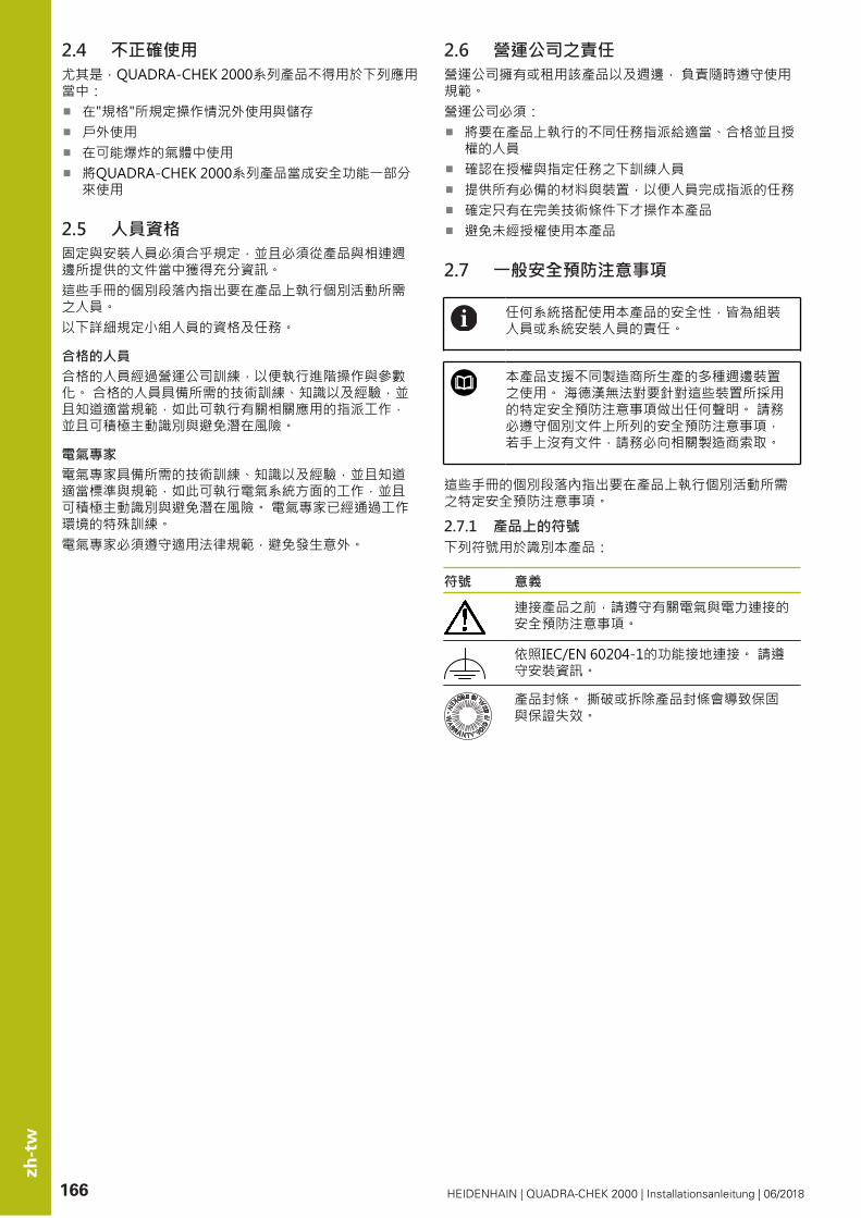
zh
-tw
166 HEIDENHAIN | QUADRA-CHEK 2000 | Installationsanleitung | 06/2018
2.4 不正確使用尤其是,QUADRA-CHEK 2000系列產品不得用於下列應用當中:
在"規格"所規定操作情況外使用與儲存戶外使用在可能爆炸的氣體中使用將QUADRA-CHEK 2000系列產品當成安全功能一部分來使用
2.5 人員資格固定與安裝人員必須合乎規定,並且必須從產品與相連週邊所提供的文件當中獲得充分資訊。這些手冊的個別段落內指出要在產品上執行個別活動所需之人員。以下詳細規定小組人員的資格及任務。
合格的人員合格的人員經過營運公司訓練,以便執行進階操作與參數化。 合格的人員具備所需的技術訓練、知識以及經驗,並且知道適當規範,如此可執行有關相關應用的指派工作,並且可積極主動識別與避免潛在風險。
電氣專家電氣專家具備所需的技術訓練、知識以及經驗,並且知道適當標準與規範,如此可執行電氣系統方面的工作,並且可積極主動識別與避免潛在風險。 電氣專家已經通過工作環境的特殊訓練。電氣專家必須遵守適用法律規範,避免發生意外。
2.6 營運公司之責任營運公司擁有或租用該產品以及週邊, 負責隨時遵守使用規範。營運公司必須:
將要在產品上執行的不同任務指派給適當、合格並且授權的人員確認在授權與指定任務之下訓練人員提供所有必備的材料與裝置,以便人員完成指派的任務確定只有在完美技術條件下才操作本產品避免未經授權使用本產品
2.7 一般安全預防注意事項
任何系統搭配使用本產品的安全性,皆為組裝人員或系統安裝人員的責任。
本產品支援不同製造商所生產的多種週邊裝置之使用。 海德漢無法對要針對這些裝置所採用的特定安全預防注意事項做出任何聲明。 請務必遵守個別文件上所列的安全預防注意事項,若手上沒有文件,請務必向相關製造商索取。
這些手冊的個別段落內指出要在產品上執行個別活動所需之特定安全預防注意事項。
2.7.1 產品上的符號下列符號用於識別本產品:
符號 意義
連接產品之前,請遵守有關電氣與電力連接的安全預防注意事項。
依照IEC/EN 60204-1的功能接地連接。 請遵守安裝資訊。
產品封條。 撕破或拆除產品封條會導致保固與保證失效。

zh
-tw
HEIDENHAIN | QUADRA-CHEK 2000 | Installationsanleitung | 06/2018 167
2.7.2 電氣安全預防注意事項
警告打開單元時,會有接觸到帶電零件的危險,
如此會導致觸電、燒傷或死亡。
請勿打開外殼只允許製造商進入產品內部
警告直接或間接接觸到帶電零件,會有危險電量通過人體的危險。
如此會導致觸電、燒傷或死亡。
只能由受過訓練的電氣專家才能在電氣系統以及帶電零件上工作針對電力連接以及所有介面連接,只能使用符合適用標準的纜線與接頭請立即由製造商更換失效的電氣零件請定期檢查產品上所有連接纜線以及所有連接。 例如連接鬆脫或纜線燒焦這類缺失必須立刻排除
注意事項產品內部零件受損!
若打開本產品,則會導致保固與保證失效。
請勿打開外殼只允許產品製造商進入產品內部
3 運輸與儲存
3.1 概述本章節內含運輸與儲存本產品的資訊,並且提供本產品附件與可用配件的簡介。
以下步驟只能由合格的人員執行。進一步資訊: "人員資格", 頁碼 166
3.2 拆箱打開箱子的上蓋取下包裝材料拆開內容物檢查內容物是否完整檢查內容物是否受損
3.3 附件與配件3.3.1 附件出貨時包含下列物品:
Product_Name 說明
2-D展示工件
補遺(選配)
操作手冊
產品
安裝手冊

zh
-tw
168 HEIDENHAIN | QUADRA-CHEK 2000 | Installationsanleitung | 06/2018
3.3.2 配件
在本產品上透過使用許可金鑰才能啟用軟體選項。 因為要使用相關硬體組件,所以需要啟用個別軟體選項。
下列配件可供選配,並且可向HEIDENHAIN訂購:
配件群組 Product_Name ID
用於安裝
TTL的變壓器接頭 1089210-01
11 µApp變壓器接頭 1089213-01
1 Vpp變壓器接頭 1089214-01
電源線 223775-01
2 Vpp變壓器接頭 1089216-01
腳開關 681041-04
USB連接纜線 354770-xx
用於固定
多位置固定座 1089230-08
雙位置立架 1089230-06
多位置固定座 1089230-07
設備軟體選項QUADRA-CHEK 3000 OED
光纖 681049-xx
連接光纖 681049-xx
固定器 681050-xx
3.4 若在運送途中受損請貨運公司確認受損保留包裝材料以供檢查通知受損裝置的寄件方請連繫經銷商或工具機製造商來更換零件
若運送途中受損:保留包裝材料以供檢查請聯繫海德漢或工具機製造商
這也適用於運送途中受損要求更換零件時。
3.5 重新包裝與儲存請依照底下陳述的條件,仔細重新包裝與儲存本產品。
3.5.1 重新包裝本產品重新包裝應該盡可能對應原始包裝。
將所有安裝零件以及防塵蓋都重新連接至產品,就如同從原廠接收時一樣,或重新包裝在收到物品時的原廠包裝內。以下列方式重新包裝本產品
保護避免運送途中的衝擊與震動保護避免灰塵或濕氣進入
包含原始包裝內含的所有配件進一步資訊: "附件與配件", 頁碼 167包含原始包裝內含的所有文件進一步資訊: "文件的儲存以及散佈", 頁碼 163
若要將本產品送回維修中心修理:單獨送回本產品,不含配件以及量測裝置和周邊
3.5.2 產品儲存如上述包裝產品遵守規定的環境情況進一步資訊: "規格", 頁碼 173檢查運輸或長時間儲存之後產品是否受損

zh
-tw
HEIDENHAIN | QUADRA-CHEK 2000 | Installationsanleitung | 06/2018 169
4 安裝
4.1 概述本章節說明本產品的固接。 其中包含有關本產品如何正確固接在立架或固定架上的說明。
以下步驟只能由合格的人員執行。進一步資訊: "人員資格", 頁碼 166
4.2 產品組件
一般安裝資訊背板上提供多種安裝方式。安裝孔圖案對應於50 mm x 50mm的方格。進一步資訊: "H", 頁碼 175出貨包裝中內含裝置上多種安裝配件材料。同時需要以下物品:
Torx T20螺絲起子Torx T25螺絲起子六角扳手,寬度A/F 2.5 (雙位置立架)安裝在支撐表面上的材料
本產品必須固定在立架或固定器上,以確保正確的和預期的產品操作。
安裝在雙位置立架上雙位置立架可用20°或45°的角度固定至產品。
若以45°角將雙位置立架旋入本產品,則必須將本產品附接在該安裝槽的上端上。使用具有斜角接頭的電源纜線
使用提供的M4x8 ISO 7380內六角螺絲,將立架鎖緊至背板的下方螺紋孔
符合2.6 Nm的允許鎖緊扭力
使用固定槽(寬度 = 4.5 mm),將立架旋至支撐表面或
將裝置自由設定在所要位置上纜線從後方通過立架的兩個支架,然後通過側面開口進行連接
進一步資訊: "C", 頁碼 4
雙位置立架的尺寸進一步資訊: "J", 頁碼 176
4.2.1 安裝在多位置立架上使用提供的M4x8 ISO 14581沉頭螺絲(黑色),將立架鎖緊至背板的螺紋孔
符合2.6 Nm的允許鎖緊扭力
使用兩只M5螺絲,也可選擇性從底部將立架固定至支撐表面在調整所要的傾斜角度要固定立架: 鎖緊T25螺絲
符合螺絲T25的鎖緊扭力建議的鎖緊扭力: 5.0 Nm最大允許鎖緊扭力: 15.0 Nm
纜線從後方通過立架的兩個支架,然後通過側面開口進行連接
進一步資訊: "D", 頁碼 4
多位置立架的尺寸進一步資訊: "K", 頁碼 176
zh
-tw
170 HEIDENHAIN | QUADRA-CHEK 2000 | Installationsanleitung | 06/2018
4.2.2 安裝在多位置固定架上使用提供的M4x8 ISO 14581沉頭螺絲(黑色),將固定架鎖緊至背板的螺紋孔
符合2.6 Nm的允許鎖緊扭力
使用內附的M8螺絲、墊片、把手以及M8六角螺帽將固定架鎖緊至臂在調整所要的傾斜角度要固定固定架: 鎖緊T25螺絲
符合螺絲T25的鎖緊扭力建議的鎖緊扭力: 5.0 Nm最大允許鎖緊扭力: 15.0 Nm
纜線從後方通過固定架的兩個支架,然後通過側面開口進行連接
進一步資訊: "E", 頁碼 4
多位置固定器的尺寸進一步資訊: "L", 頁碼 177
5 安裝
5.1 概述本章節說明本產品的安裝。內含有關本產品連接的資訊,以及有關如何正確連接周邊裝置的說明。
以下步驟只能由合格的人員執行。進一步資訊: "人員資格", 頁碼 166
5.2 一般資訊
注意事項來自高電磁發射源的干擾!
周邊裝置,例如頻率逆變器或伺服驅動器,也可導致干擾。
要提高對於電磁影響的雜訊抗擾度:使用依照IEC/EN 60204-1的選擇性功能接地連接只使用具有連續屏蔽的USB周邊,例如使用金屬膜與金屬編織網或金屬外殼, 編織網的覆蓋程度必須85 %或更高。 該屏蔽必須環繞連接接頭的整個四周(360°連接)。
注意事項接合與中斷接合連接的元件!
內部組件受損的風險。
當單元的電源開啟時勿連接或中斷連接任何連接中的元件

zh
-tw
HEIDENHAIN | QUADRA-CHEK 2000 | Installationsanleitung | 06/2018 171
注意事項靜電放電(ESD)!
本產品內含會遭受靜電放電(ESD)損壞的靜電敏感組件。
請確實遵守處理ESD敏感零件的安全預防注意事項在未確定適當接地之前,請勿觸摸接頭接腳進行產品連接時,請戴上接地ESD腕帶
注意事項配線錯誤對本產品的損害!
輸入或輸出不正確的配線可能導致本產品和周邊裝置受損。
符合本產品的接腳配置以及技術資料只指派已經使用的接腳或電線
進一步資訊: "規格", 頁碼 173
5.3 產品概述裝置背板上的連接附有防塵蓋保護,避免髒污與受損。
注意事項若防塵蓋遺失,則會導致髒污或受損!
若未使用的連接未安裝防塵蓋,這會妨礙接點正常運作或遭毀壞。
只有連接量測裝置或周邊裝置時才能拆除防塵蓋若移除量測裝置或周邊,請重新裝回防塵蓋
編碼器的連接類型依產品版本而不同。
背板不含防塵蓋進一步資訊: "A", 頁碼 4
連接無關於軟體選項:2 X113:15-pin D-sub連接,例如用於腳開關或接觸式
探針編碼器的D-sub連接,依照預設啟用2個輸入,另一個輸入可選擇性啟用X1至X3:裝置變化含15-pin D-sub連接,用於含1 VPP介面的編碼器
X21至X23:裝置變化含9-pin D-sub連接,用於含TTL介面的編碼器
3
X1、X2、X21:裝置變化含15-pin D-sub連接,用於含1 VPP介面的編碼器,以及一個9-pin D-sub連接,用於含TTL介面的編碼器RJ45乙太網路連接4X116:與後續系統或PC通訊以及資料交換的連接USB連線5X32:用於印表機、輸入裝置或USB大容量儲存裝置的USB 2.0高速連接埠(Type A)
6 依照IEC/EN 60204-1的功能接地連接7 X100:電源開關與電源連接8 喇叭
連接取決於軟體選項:連接光學尋邊器進行加工點量測X107:來自光源的光波導參考輸入
1
X108:來自投射畫面的光波導輸入
5.4 連接編碼器拆除並存放防塵蓋纜線路徑因安裝變化而有不同,請參閱進一步資訊: "產品組件", 頁碼 169將編碼器纜線緊連至個別連接,請參閱進一步資訊: "產品概述", 頁碼 171若纜線接頭包含安裝螺絲,請勿旋轉過緊
接腳配置X1、X2、X3進一步資訊: "1 VSS", 頁碼 178
接腳配置X21、X22、X23進一步資訊: "TTL", 頁碼 178
zh
-tw
172 HEIDENHAIN | QUADRA-CHEK 2000 | Installationsanleitung | 06/2018
5.5 連接光學尋邊器拆除並存放防塵蓋光波導路徑因安裝變化而有不同,請參閱進一步資訊: "產品組件", 頁碼 169
請遵守製造商有關光波導的最大彎曲半徑之規格
將光源(參考)的光波導連接至連接X107將來自投射螢幕的光波導連接至連接X108
進一步資訊: "產品概述", 頁碼 171
接腳配置X107、X108進一步資訊: "OED", 頁碼 178
5.6 切換輸入與輸出的配線
根據要連接的週邊,需由電氣專家進行連接工作。範例: 超出安全額外低電壓(SELV)進一步資訊: "人員資格", 頁碼 166
編碼器滿足標準IEC61010-1的要求, 僅當從輔助電路以限制電流提供電源予周邊裝置為按照IEC61010-1第三版, 第9.4節或功率限制為按 IEC60950-1第二版, 2.5節或從如在UL1310規定的第2類次級電路。代替 IEC 61010-1第三版, 第9.4節,標準的相應章節 DIN EN 61010-1, EN 61010-1, UL61010-1及CAN/CSA-C22.2 No. 61010-1及, 代替 IEC 60950-1第二版, 第2.5節,標準的相應章節 DIN EN 60950-1, EN 60950-1, UL60950-1, CAN/CSA-C22.2 No. 60950-1 可以適用。
拆除並存放防塵蓋纜線路徑因安裝變化而有不同
進一步資訊: "產品組件", 頁碼 169將周邊的連接纜線緊連至其接頭
進一步資訊: "產品概述", 頁碼 171若纜線接頭包含安裝螺絲,請勿旋轉過緊
在裝置設定中,必須將數位或類比輸入與輸出指定至該特定切換功能。
X113的接腳配置進一步資訊: "X113", 頁碼 179
5.7 Drucker anschließen
連接USB印表機拆除並存放防塵蓋纜線路徑因安裝變化而有不同,請參閱進一步資訊: "產品組件", 頁碼 169將USB印表機連接至USB Type A連接(、X32)。確定USB纜線接頭完全插入 進一步資訊: "產品概述", 頁碼 171
接腳配置、X32進一步資訊: "USB", 頁碼 178
連接乙太網路印表機拆除並存放防塵蓋纜線路徑因安裝變化而有不同,請參閱進一步資訊: "產品組件", 頁碼 169使用標準CAT.5纜線,將乙太網路印表機連接至乙太網路連接埠X116。 纜線接頭必須緊密卡住連接埠,請參閱進一步資訊: "產品概述", 頁碼 171
接腳配置X116進一步資訊: "RJ45", 頁碼 179
5.8 連接條碼掃描器
以下條碼掃描器可連接至本產品:COGNEX DataMan 8600 (含USB序列模組)
拆除並存放防塵蓋纜線路徑因安裝變化而有不同,請參閱進一步資訊: "產品組件", 頁碼 169將條碼掃描器連接至USB Type A連接(、X32)。確定USB纜線接頭完全插入 進一步資訊: "產品概述", 頁碼 171
接腳配置、X32進一步資訊: "USB", 頁碼 178
5.9 連接輸入裝置拆除並存放防塵蓋纜線路徑因安裝變化而有不同,請參閱進一步資訊: "產品組件", 頁碼 169將USB滑鼠或USB鍵盤連接至USB Type A連接(、X32)。確定USB纜線接頭完全插入 進一步資訊: "產品概述", 頁碼 171
接腳配置、X32進一步資訊: "USB", 頁碼 178

zh
-tw
HEIDENHAIN | QUADRA-CHEK 2000 | Installationsanleitung | 06/2018 173
5.10 連接網路周邊拆除並存放防塵蓋纜線路徑因安裝變化而有不同
進一步資訊: "產品組件", 頁碼 169使用標準CAT.5纜線,將網路周邊連接至乙太網路連接埠X116。 纜線接頭必須緊密卡住連接埠
進一步資訊: "產品概述", 頁碼 171
接腳配置X116進一步資訊: "RJ45", 頁碼 179
5.11 連接線路電壓
警告觸電的危險!
電氣裝置接地不當會有觸電造成人員重傷或死亡的風險。
總是使用3線式電源線確定接地線正確連接至建築物電氣安裝的接地
警告錯誤的電源線會有起火的風險!
使用不符合安裝地點要求的電源線可能會有起火的風險。
只能使用至少符合產品安裝國的國家要求的電源線
使用符合需求的電源線將電源接頭連接至3線式接地電源插座
進一步資訊: "產品概述", 頁碼 171
接腳配置X100
進一步資訊: "X100", 頁碼 178
6 規格
6.1 概述本章節包含產品資料概述以及含有本產品尺寸和裝配尺寸的圖示。
6.2 編碼器資料
裝置
外殼 鋁銑削前板 + 鑄造背板
外殼尺寸 200 mm x 169 mm x 41 mm
扣件系統,配合尺寸
固接孔圖案50 mm x 50 mm
顯示器
視覺顯示器單元 LCD寬螢幕(15:9)彩色螢幕17.8 cm (7")800 x 480畫素
顯示步階 可選擇,最低0.00001 mm
使用者介面 使用者介面(GUI)含觸控螢幕
電氣資料
電壓供應 AC 100 V ...240 V (±10 %)
50 Hz ...60 Hz (±5 %)
最大輸入功率38 W
暫存區電池 CR2477型鋰電池;3.0 V
過電壓類別 II
編碼器輸入的數量 2 (可透過軟體選項啟用1額外輸入)
編碼器介面 11μA:最大電流300 mA,最高輸入頻率150 kHz1 VPP:最大電流300 mA,最高輸入頻率400 kHzTTL:最大電流300 mA,最高輸入頻率5 MHz
在1 VPP上的補間 4096倍
接觸式探針連接 電壓供應DC 5 V或DC 12 V5 V或浮動切換輸出4數位輸入1數位輸出含海德漢纜線的最長纜線長度30 m
連接光學尋邊器 2個F-SMA插座(螺紋設計1/4-36 UNS-2A)
數位輸入 TTL DC 0 V ... +5 V
數位輸出 TTL DC 0 V ... +5 VMaximum load 1 kΩ

zh
-tw
174 HEIDENHAIN | QUADRA-CHEK 2000 | Installationsanleitung | 06/2018
電氣資料
資料介面 1高速USB 2.0 (Type A),每一USB連接埠的最大電流500 mA1 10/100 Mbit/1 Gb乙太網路(RJ45)
環境
操作溫度 0 °C ... 45 ℃
儲藏溫度 -20 °C ... 70 ℃
空氣相對溼度 10 % ... 80 % r.H.,無凝結
高度 ≤ 2000 m
一般資訊
指令 EMC指令2014/30/EU低電壓指令2014/35/EURoHS指令2011/65/EU
汙染程度 2
防護EN 60529 前面板與側面板: IP 65後面板: IP 40
重量 1.3 kg含雙位置立架:大約1.45 kg含多位置立架: 1.95 kg含多位置固定器: 1.65 kg
6.3 產品尺寸與匹配尺寸進一步資訊: 頁碼 175以及以下頁面。圖中所有尺寸單位皆為公釐。

HEIDENHAIN | QUADRA-CHEK 2000 | Installationsanleitung | 06/2018 175
G
HEIDENHAIN
169
200 33.8
11340.7±1
H
AC 100 V ... 240 V50 Hz ... 60 Hz
(max. 38 W)
HEIDENHAIN
X113
X3
X2
X1
X100
X32
X116
X108
X107
140
5043.5
115128
10390
65
37.5
15.5
0
8880
7264
2475
50
67.5

176 HEIDENHAIN | QUADRA-CHEK 2000 | Installationsanleitung | 06/2018
J
80100
132±216
8±1ISO 7092-4
ISO 7380-M4x8Md = 2.6 Nm
20°
4.55
7099
150±2
150±
1
ISO 7092-4ISO 7380-M4x8
Md = 2.6 Nm
45°
4.55
504.
5 504.
5
K
15.25
4.5
ISO 14581-M4x8Md = 2.6 Nm
T25Md = 15 Nm max.
10°
80°
6.6
10
185±
1
18.75130
170
51
M5
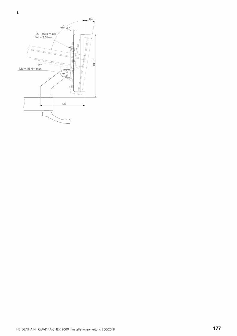
HEIDENHAIN | QUADRA-CHEK 2000 | Installationsanleitung | 06/2018 177
L
4.5
ISO 14581-M4x8Md = 2.6 Nm
T25Md = 15 Nm max.
10°
80°
133
186±
1

178 HEIDENHAIN | QUADRA-CHEK 2000 | Installationsanleitung | 06/2018
1 VSS
(X1, X2, X3)
1 VSS
1 2 3 4 5 6 7 8
A+ 0 V B+ UP / / R- /
9 10 11 12 13 14 15
A- Sensor 0 V B- Sensor UP / R+ /
TTL
(X21, X22, X23)
TTL
1 2 3 4 5 6 7 8 9
/ Ua1 Ua1 Ua2 Ua2 0 V Up Ua0 Ua0
USB
(X32)
4 3 2 1
1 2 3 4
DC 5 V Data (-) Data (+) GND
X100
1 2 3
L/N N/L
OED
(X107, X108)
1
In

HEIDENHAIN | QUADRA-CHEK 2000 | Installationsanleitung | 06/2018 179
X113
1 2 3 4 5 6 7 8
LED+ B 5 V B 12 V Dout 0 DC 12 V DC 5 V Din 0 GND
9 10 11 12 13 14 15
Din 1 Din 2 TP GND TP Din 3 LED-
B - Probe signals, readiness
TP - Touch Probe, normally closed
Digital inputs: Digital outputs:
Din 0...3X113
GND
DC 5 V
Dout 0
GND
X113
DC 5 V TTL
RJ45
(X116)
1 2 3 4 5 6 7 8
1 2 3 4 5 6 7 8
D1+ (TX+) D1- (TX-) D2+ (RX+) D3+ D3- D2- (RX-) D4+ D4-

DR. JOHANNES HEIDENHAIN GmbHDr.-Johannes-Heidenhain-Straße 583301 Traunreut, Germany +49 8669 31-0 +49 8669 32-5061E-mail: [email protected]
Technical support +49 8669 32-1000Measuring systems +49 8669 31-3104
E-mail: [email protected] support +49 8669 31-3101
E-mail: [email protected] programming +49 8669 31-3103
E-mail: [email protected] programming +49 8669 31-3102
E-mail: [email protected] programming +49 8669 31-3106
E-mail: [email protected]
www.heidenhain.de
Originaldokumentation
1246325-90 · 00 · 06/2018*I1246325-90*