Embed Size (px)
Citation preview

QTO
User
Manual


Contents
Introduction to QTO ......................................................................................................... 5
Objectives of QTO ........................................................................................................... 5
Getting Started ................................................................................................................ 5
QTO Manager .................................................................................................................. 6
QTO Layout ..................................................................................................................... 7
Bill of Quantities ............................................................................................................... 8
Measure Folders .............................................................................................................. 9
Drawings........................................................................................................................ 10
Zooming and Scrolling ................................................................................................... 10
Calibrate the Drawing .................................................................................................... 11
2D Measurement Tools ................................................................................................. 13
Measurement ................................................................................................................. 14
Attaching Bill Items to the Measure ............................................................................... 21
Variables ....................................................................................................................... 22
Updating the Bill of Quantities in Candy ......................................................................... 25
Templates ...................................................................................................................... 27
Customising the Display ................................................................................................ 29
Revised Drawings .......................................................................................................... 32
Reports .......................................................................................................................... 33


5
Introduction to QTO
QTO provides fast and accurate measurement from 2D drawings. Bills of Quantities can be created directly in QTO or existing Bills of Quantities can be seamlessly updated for progress or final quantities.
Objectives of QTO
Measure quantities from 2D drawings Create or update a Bill of Quantities with all the functionality of Candy Update quantities after drawing revisions Measure for Bill, Final and Progress quantities Provide quantities for the BOQ and Valuations
Getting Started
Requirements
There are basic requirements to use QTO:
to have a Bill of Quantities set up in the Candy job
to have a basic knowledge of Candy
to understand the principles of measurement
Creating a Bill of Quantities
If there is no existing Bill of Quantities, a BOQ document must be created, copied or imported into the Candy job. QTO will use the BOQ items from this document to create the new Bill of Quantities.
A bill of quantity document can be created by:
Copying from another Candy job
Importing from an external file such as Excel or WinQS
It would be preferable to have a Candy job with a BOQ document available in a Candy directory. In this case, duplicate the job and rename. This job is now ready for QTO.
Updating an existing Bill of Quantities
This job is ready for QTO as the Bill of Quantities has already been created.

6
QTO Manager
QTO Manager is the place where Take-offs are created, stored, renamed, deleted, accessed and where the quantities from the Take-offs are copied back to the Candy Bill of Quantities.
Take-offs should be organised in a structured hierarchy such as below.
QTO is accessed from Candy by going to Estimating > Bill Prep > QTO Manager. To add a new Take-off, use the New button in the bottom right corner. Double-click on a Take-off to select it or highlight and use the Select button.
QTO Take-offs can be organised under headings and sub-headings. To create a new heading or sub-heading, use the New ⇧ button.
7
QTO Layout
Once the Take-off has been selected, the QTO interface is displayed as shown below.
There are six panels available to the QTO interface:
1. The current bill of quantities 2. A list of the drawings to be used in the Take-offs 3. Templates of common measurements for re-use 4. A list of Measurement folders 5. A list of Take-offs 6. Drawing area
Drawings display area
Bill of Quantities display area
List of Take-offs
List of measure folders
List of Take-off templates
List of drawings used

8
Bill of Quantities
The Bill of Quantities panel is blank when going into a Take-off for the first time. Use the “Bill items” icon to update the QTO Bill of Quantities and to copy from Candy for the first time. The BOQ panel may be closed and made available as required (see below).
Adding Bill Items
New items have to be created in the Candy bill to be displayed in QTO. Once the items have been created, use the same icon again to update the QTO Bill of Quantities.
Deleting Bill Items
Delete the items in the Candy job, update the QTO bill and the items will be deleted from QTO. All records of the deleted items and any quantities previously measured against them are deleted.
Use this to close the BOQ panel
After selecting the BOQ icon the BOQ is displayed here
Use this icon to update the BOQ
Use this icon to open the BOQ panel

9
Measure Folders
Measure folders are used to organise Take-offs into specific areas or locations. These are clearly referenced when the QTO quantities are transferred to the Candy Bill of Quantities. Measure folders and Sub-folders can be created to your specific requirements. A Measure folder can extend over multiple drawings. To display the Measure folders use the Measure folder tab. Many Measure folders can be created and they will be listed in this panel.
Adding a Folder
To make folders and sub-folders, Right-click in the Measure folder panel at the required position of the folder structure.
Renaming a Folder
The default name for all folders that are created is “Measure folder”, highlight this and rename.
Change the name of the Measure folder
To display the Measure folders

10
Drawings
Attach a Drawing:
Drawings are added to QTO by selecting the drawing icon and browsing for the correct drawing.
Due to the size of drawing files, they are not saved inside QTO but are attached using the file location. It is strongly suggested, (but not mandatory), that a separate directory be made for all drawings.
File types
QTO accepts drawings in the following file formats - PDF, DXF, and DWG.
Opening a Drawing
Use the Drawing tab to display the list of attached drawings. To open a drawing right-click on the drawing reference and select Open from the menu.
Delete a Drawing
To delete a drawing right-click on the drawing reference and select Delete from the menu. Be aware that when a drawing is deleted all Take-offs measured from the drawing are also deleted and the bill quantities adjusted accordingly.
Background
Certain drawings are better viewed with a dark background. To switch from the default light background, select the Drawing menu on the menu bar, then Background and then select Light or Dark.
Open drawings are shown here
Use this icon to attach a drawing
Use this tab to display the drawing list
List of attached drawings
11
Zooming and Scrolling
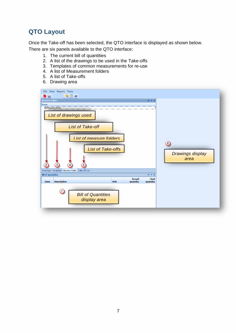
The Rectangular Zoom tool is a quick way to zoom to a selected area of a drawing. Select this tool and drag to select the required section of the drawing – this will then zoom and display the selected section to fill the drawing screen area.
Rolling the mouse wheel or using the Zoom in and Zoom out tools expand or contract the drawing.
To move the drawing around the drawing panel, push the mouse wheel in and move the mouse around, or use the scroll bars.
Calibrate the Drawing
The scale is unknown in PDF format drawings and has to be calibrated. Select the Calibration tool and click on the start point and end point of a known dimension. The dimension must be entered in the dialogue box to establish the scale. A drawing has
Rectangular Zoom
Zoom in & Zoom out

12
only to be calibrated once.
Dimension
Calibration tool
Start & End points

13
2D Measurement Tools
QTO measurement tools are displayed vertically to the left of the drawing panel and contain the tools required for measurement of drawings. These are displayed when a drawing is opened.
Number Tool Use the Number tool to count items such as windows, doors, openings, manholes.
Length Tool Use the length tool for linear measurements such as drainage trenches, pipework, and perimeter work in general.
Area Tool Use the Area Tool for measurement of an area.
Arc Tool Use the Arc tool for measurement of circular work. Select the start point of the curve, the end point and then any other point on the curve - this will give the length of the arc or circumference and area of the segment or circle.
2D Measurement tools
14
Measurement
Measuring an area
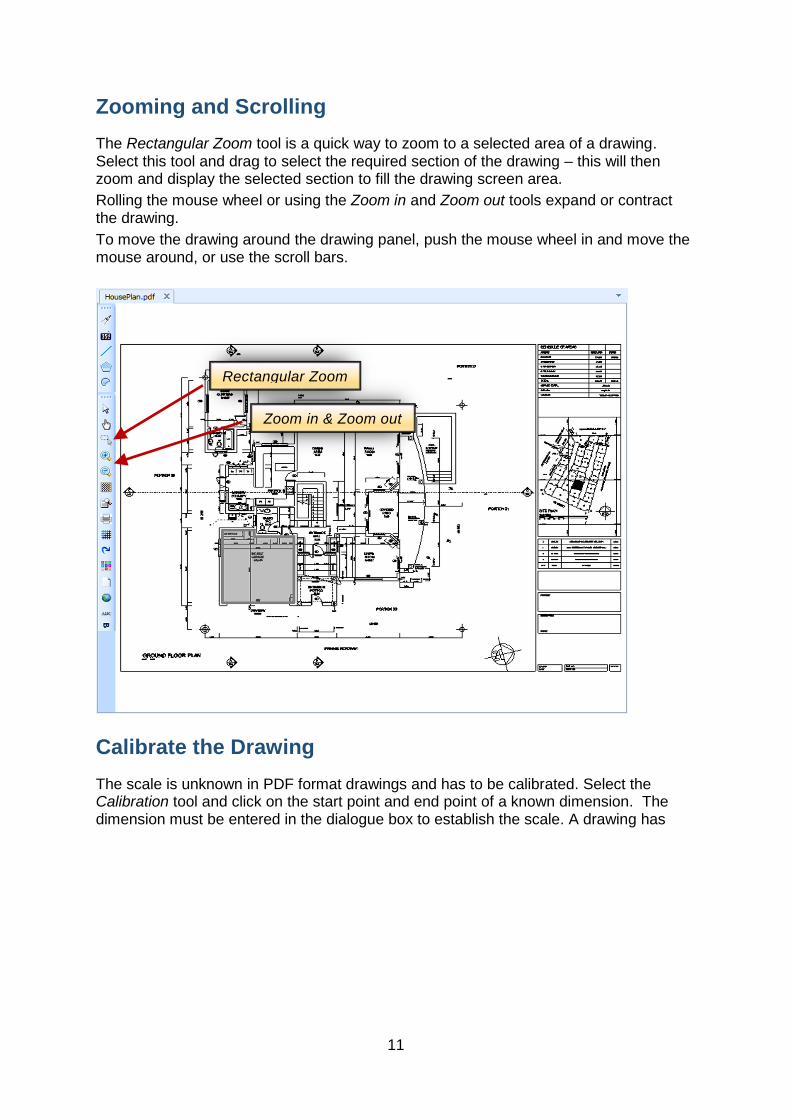
Select the Area tool to start the area measurement. Click on the start point of the area to be measured.
Click successively on each of the points of the area being measured. End the area measurement by right-clicking on the start point (or right-click anywhere and the line will connect to the origin).
The points that are recorded on the drawing are subsequently referred to as “Grip points”
Area tool
Start point

15
The area measured is shown against the item together with the unit of measure of the tool. The dimensions that are produced by the Area tool are the area and perimeter as well as the number of clicks.
The area measured is identified by a red line above known as the “Mark-up”.
1 Mark-up
Area measure

16
Measuring a length
Select the Length tool to start the linear measurement. Click on the start point of the length to be measured.
Click successively on each of the points of the length being measured. End the length measurement by right-clicking on the last point of the length.
Measuring a Number
Select the Number tool to start the count. Click on each element that is to be counted and right click on the last element to complete the measurement.
Mark-up of Number tool
Mark-up of Length tool

17
Mark-up
Take-offs are identified on the drawing by using different colours for the “Mark-up”.
The colour of the Mark-up used to represent the measurement is changed by right-click on the colour sample and select a new colour from the colour chart.

18
Quantity Type
The Type identifies whether the measure is for Bill, Claimed, Actual or Final Quantities.
To change the default type go to Measure > Default Quantity type and change as required.
To change the quantity Type for an individual Take-off, right-click in the Type field and change as required.
Change default Type
Change Take-off type

19
Continue the Take-off
There will be occasions when a Take-off is not completed and has to be continued. Typical examples are when counting columns, windows or doors on a large drawing.
Instead of starting a new Take-off each time, select the continue button and continue with the Take-off.
Fixing a mistake
Mistakes can easily be rectified in QTO by:
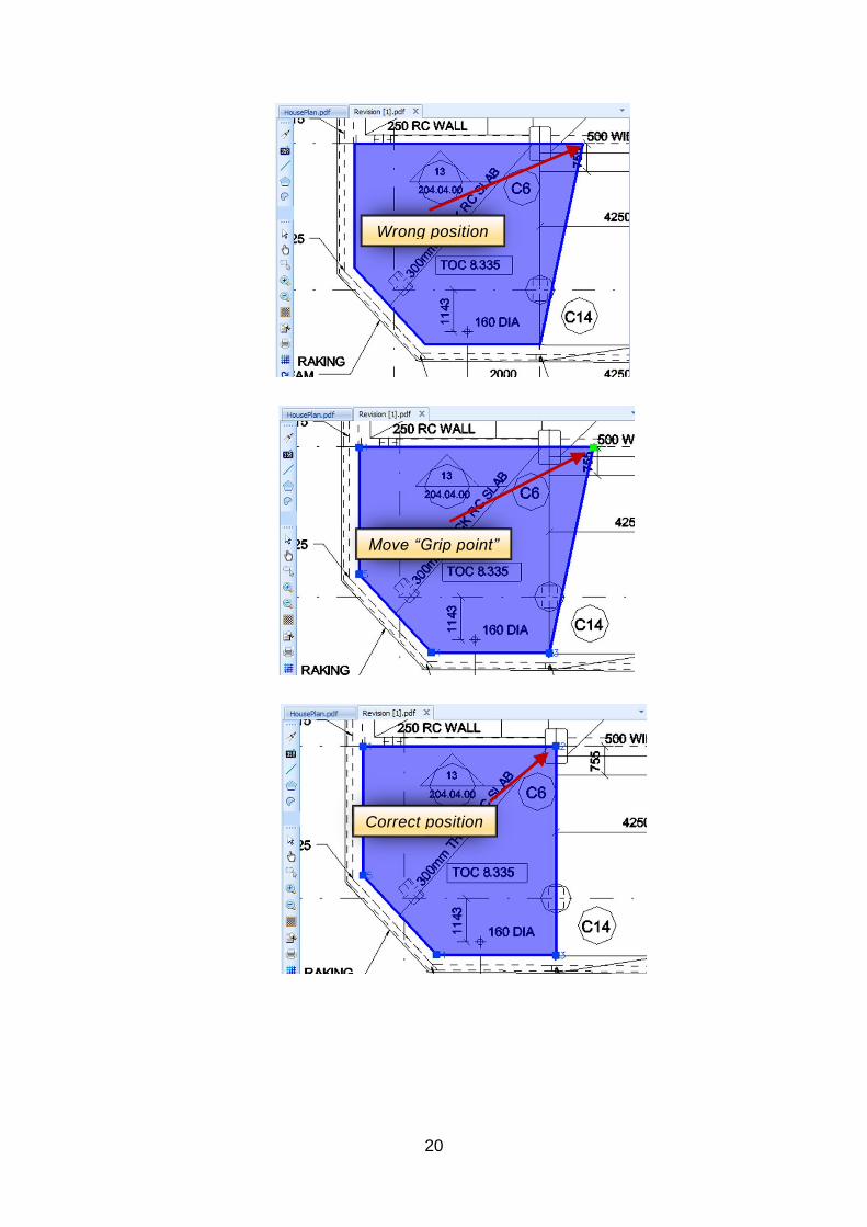
Moving a Point
Position the cursor on the Mark-Up that is to be changed and click to display the Points currently used. Select the Point to be moved and click, position the cursor in the new position and click again, the Point has now been relocated. Double-click to display the revised Mark-Up.
Adding a Grip Point
Position the cursor on the Mark-Up where the additional Point is required and right-click to display the dialogue box, select Insert point. Then select between which point the additional Point is to be added, then position by following the steps above under the heading “Moving a Point.”
Deleting a Point
Position the cursor on the Point that must be deleted, right-click to display the dialogue box and select Delete Point.
Delete a Mark-Up
Position the cursor on any position of the Mark-Up that needs to be deleted, right-click to display the dialogue box and select Delete Key.
Continue button
20
Wrong position
Move “Grip point”
Correct position

21
Attaching Bill Items to the Measure
The next step is to use the measured dimensions to create quantities in the bill. The Bill of Quantities needs to be displayed so that bill items can be dragged onto the Take-off.
Double-click on the Bill of Quantities tab and the bill will float free. Position it at a convenient place – much easier when using multiple screens.
Select a bill item1 that uses these dimensions to calculate its quantity and drag it onto the Take-off item2.
Drag the word “Area” into the formula field of the formwork item3.
This calculates the formula to arrive at the quantity which is displayed against the bill item in the Take-off. Note that the quantity has also been recorded in the QTO Bill of Quantities below4.
2 3
1 4

22
Variables
The above example was simple as only the area was required.
Variables will be required in the measurement to calculate the correct quantity for multiple Bill items using one Take-off measurement. The internal area of a building will give the area of the floor and ceiling but would need a variable (thickness) to calculate the volume of concrete in the surface bed and in this example the thickness of the slab is required to calculate the volume of concrete.
Creating a Variable
Right Click in the measurement area displays the drop down box and select Add1.
This now extends the measurement area to include the Heading Variables, open up the Variables Heading and the first blank variable is displayed2.
Enter “SlabT” in the name field, “0.3” in the value field and “m” in the unit field.
1
2

23
Properties
A variable is made up of five fields:
Name: This is the reference which identifies the variable from others in the Take-off, it can be as brief as H (for height) or T (for thickness), the reference is user defined and will be used in formulae (explained below).
Value: The variable may have a simple value or the value may be derived from a formula (explained below). A simple value is entered in this cell.
Unit: For reference purposes the unit type is entered here.
Formula When a formula is used to calculate the variable value the formula is entered here. Formulae can make use of Dimension names, Variables and supports the following Mathematical & Trigonometrical functions.
Radians: Converts Radians to Degrees
Example Radians(3.14) = 180
Degrees: Converts Degrees to Radians
Example: Degrees(180) = 3.14
Sin() and Asin()
Cos() and Acos()
Tan and Atan()
Abs: Converts any number to a positive
Example: Abs(-4) = 4
Pow: Raise to the power
Example: Pow(2,4) = 16
Round: Round to a whole number
Example: Round(10.2) = 10
Sqrt: Calculates the Square root
Example: Sqrt(4) = 2
PI: The ratio of circumference of circle to diameter, PI = 3.14
Only variables above the variable being entered can be used in the formula.
24
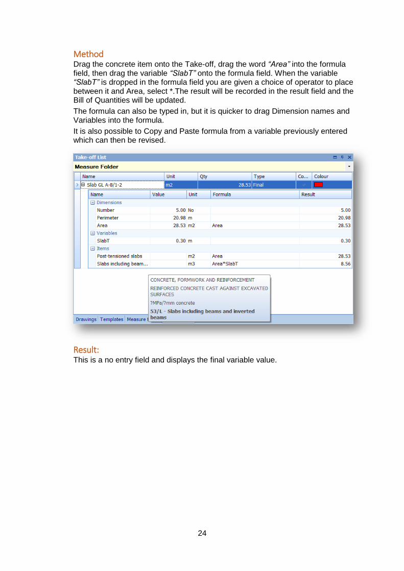
Method Drag the concrete item onto the Take-off, drag the word “Area” into the formula field, then drag the variable “SlabT” onto the formula field. When the variable “SlabT” is dropped in the formula field you are given a choice of operator to place between it and Area, select *.The result will be recorded in the result field and the Bill of Quantities will be updated.
The formula can also be typed in, but it is quicker to drag Dimension names and Variables into the formula.
It is also possible to Copy and Paste formula from a variable previously entered which can then be revised.
Result: This is a no entry field and displays the final variable value.

25
Updating the Bill of Quantities in Candy
When the measure is complete, the QTO quantities can be synchronised with the Bill of Quantities by right-clicking on the selected file and using “Copy Quantities from QTO”.
After this process all the QTO Take-offs are visible in the Bill of Quantities stating the QTO type, QTO quantity, drawing, Measure folder and Take-off references.

26
The quantities can then be copied into the relevant columns in the Bill of Quantities.
In this example the Final Quantity is copied into the Bill of Quantities by right-click in the column heading “Final Quantity” and selecting, “Copy Final from QTO”.
On the screen-shot below, only the Take-off marked Final is transferred.
Right click in heading
Select Copy final from QTO

27
Templates
The most efficient way to measure the job is to make use of job templates. Templates can be created to include variables, formulae and Bill of Quantity items which will be needed many times to measure the job.
Create a Template
To create a new template select the Template tab, right-click and choose “New Template” then name the template and select the Measurement type as below.
Once complete, the template is recorded in the template directory. When the new template is accessed, a blank template will be displayed as per picture below. The template is now ready to be populated with variables, formulae and Bill of Quantity items. Refer to the relevant section for helps on these.
Right click and select
Name & select measurement type

28
Measuring from the Template
To measure from a template, drag the template name onto the drawing and then continue the measure as described previously. When the measurement is complete go to the Take-off tab where the measurement is recorded and all quantities will have been updated. The default name on the Take-off list will be the name of the Template that was used, it is important to change the name of this Take-off to identify where the measurement came from.
Using Templates
The use of templates will save time as it eliminates all the preparation work for repetitive type measurements.
Typical examples of templates:
Internal Perimeter - including all Bill of Quantity items that require a perimeter measure, a good tip is to select the Area type for this template, as this will also give the internal perimeter and by the use of formula in variables, the centre line and external perimeters can be used.
Window - including all Bill of Quantity items that will be affected by the installation of a window. The Number type would be selected, counting the Window type and with the use of variables, deductions for external walling, internal and external finishes are made and items such as lintols, reveals, cavity closers, cills can be attached.
Door - including all Bill of Quantity items that will be affected by the installation of a door. The Number type would be selected, counting the Door type and with the use of variables, deductions for walling, internal and external finishes are made and items such as frames, ironmongery, lintols, reveals, cavity closers can be attached.
Downstand Beam - The linear tool would be selected, and with variables will measure the concrete volume, formwork to the sides and soffit of beams and make deduction for the formwork to soffit of slabs.
Measure items Drag template to drawing area
29
Customising the Display
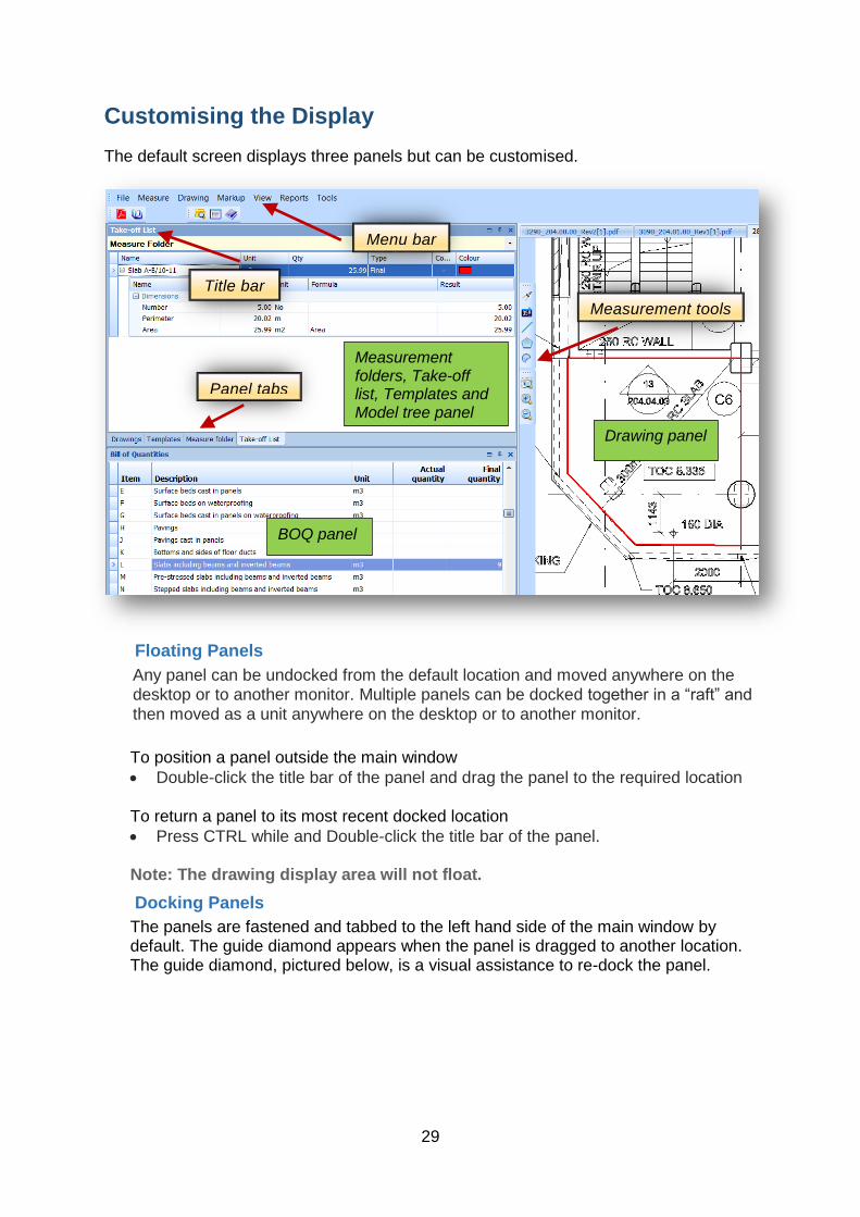
The default screen displays three panels but can be customised.
Floating Panels
Any panel can be undocked from the default location and moved anywhere on the desktop or to another monitor. Multiple panels can be docked together in a “raft” and
then moved as a unit anywhere on the desktop or to another monitor.
To position a panel outside the main window
Double-click the title bar of the panel and drag the panel to the required location
To return a panel to its most recent docked location
Press CTRL while and Double-click the title bar of the panel.
Note: The drawing display area will not float.
Docking Panels
The panels are fastened and tabbed to the left hand side of the main window by default. The guide diamond appears when the panel is dragged to another location. The guide diamond, pictured below, is a visual assistance to re-dock the panel.
Measurement tools
Panel tabs
Menu bar
Title bar
Measurement folders, Take-off list, Templates and Model tree panel
BOQ panel
Drawing panel

30
To dock a panel
1. Click on the panel 2. Drag the window toward the middle of the main window 3. The guide diamond appears. The four arrows of the diamond point toward the
four sides of the pane 4. When the panel reaches the required location, move the pointer over the
corresponding portion of the guide diamond. The designated area will be shaded
5. To dock the panel in the position indicated, release the mouse button 6. Alternatively, a panel can be docked to a portion of one of the side walls of the
main window. Drag the panel to the side until a secondary guide diamond appears. Click one of the four arrows to dock the tool window to that portion of the side wall
Auto hide panels
The pushpin icon resembles the following graphic when Auto Hide is enabled.
Auto Hide Disabled Auto Hide Enabled
Rest panels
Tools>Layout>Reset Layout
Each panel can be separated and moved around the screen to customise the interface layout. Click and drag the panel tab, will move the panel onto any of the layout options. Interface layouts can then be saved, closed, and restored.
Multiple monitors
It is preferable but not mandatory that two or more monitors are used. The drawing panel must reside on the primary monitor but all other panels can be moved. Place the cursor on the Title Bar and drag to move the panel to a position on another monitor.

31
Column Chooser
The column chooser is an option to customise specific columns. Add or remove columns temporarily depending on the requirement. The Column chooser is available on Bill and Take-off headers. To access Column Chooser, right-click on the header.
When the column chooser is open, drag & drop the required columns into position.
Columns are removed from the display by drag and drop into the “Customisation”
panel below.
Right click on any of these title rows to display the column chooser

32
Revised Drawings
When a revised drawing is issued, it is not necessary to start the measurement process from the beginning.
The following steps should be taken to update measurements of the revised drawing using the procedures explained previously:
1. Attach the revised drawing. 2. Calibrate the drawing. 3. Open the original drawing. 4. Select the Take-off List tab. 5. With the cursor selecting the Take-off to be revised, Right Click and Copy.
Multiple Take-offs can also be selected. 6. Open the revised drawing. 7. Select the Take-off List tab, Right Click and Paste.
The original Mark-Up is now visible on the revised drawing and can now be revised to match the revised layout.
As explained above, the Take-off can be revised by using the “Continue” button or adding, deleting and moving the Grip Points.
To prevent any duplication, once the Mark-Up on the revised drawing has been successfully updated, open the original drawing, select the Take-off List and delete the original Take-off.
Note: Revising drawings is only available for the pdf and dwg file formats.

33
Reports
By selecting the Report tab on the menu bar, there will be a drop down box which allows a variety of reports to be selected.
Drawings with mark-up can also be printed by selecting the drawing tab and then print
as shown below.

34